EP3199394A1 - Nutzfahrzeugaufbau - Google Patents
Nutzfahrzeugaufbau Download PDFInfo
- Publication number
- EP3199394A1 EP3199394A1 EP16002273.7A EP16002273A EP3199394A1 EP 3199394 A1 EP3199394 A1 EP 3199394A1 EP 16002273 A EP16002273 A EP 16002273A EP 3199394 A1 EP3199394 A1 EP 3199394A1
- Authority
- EP
- European Patent Office
- Prior art keywords
- screw
- door
- commercial vehicle
- vehicle body
- washer
- Prior art date
- Legal status (The legal status is an assumption and is not a legal conclusion. Google has not performed a legal analysis and makes no representation as to the accuracy of the status listed.)
- Granted
Links
- 239000000463 material Substances 0.000 claims description 2
- 239000007769 metal material Substances 0.000 claims description 2
- 230000037431 insertion Effects 0.000 claims 1
- 238000003780 insertion Methods 0.000 claims 1
- 238000010276 construction Methods 0.000 description 4
- 238000003466 welding Methods 0.000 description 4
- 238000004519 manufacturing process Methods 0.000 description 3
- 230000007797 corrosion Effects 0.000 description 2
- 238000005260 corrosion Methods 0.000 description 2
- 239000002184 metal Substances 0.000 description 2
- 229910052751 metal Inorganic materials 0.000 description 2
- 238000000034 method Methods 0.000 description 2
- 238000004140 cleaning Methods 0.000 description 1
- 230000006378 damage Effects 0.000 description 1
- 150000002739 metals Chemical class 0.000 description 1
- 230000002093 peripheral effect Effects 0.000 description 1
- 238000012805 post-processing Methods 0.000 description 1
- 238000009419 refurbishment Methods 0.000 description 1
- 238000009423 ventilation Methods 0.000 description 1
Images

Classifications
-
- B—PERFORMING OPERATIONS; TRANSPORTING
- B60—VEHICLES IN GENERAL
- B60J—WINDOWS, WINDSCREENS, NON-FIXED ROOFS, DOORS, OR SIMILAR DEVICES FOR VEHICLES; REMOVABLE EXTERNAL PROTECTIVE COVERINGS SPECIALLY ADAPTED FOR VEHICLES
- B60J5/00—Doors
- B60J5/10—Doors arranged at the vehicle rear
- B60J5/108—Doors arranged at the vehicle rear for load transporting vehicles or public transport, e.g. lorries, trucks, buses
-
- F—MECHANICAL ENGINEERING; LIGHTING; HEATING; WEAPONS; BLASTING
- F16—ENGINEERING ELEMENTS AND UNITS; GENERAL MEASURES FOR PRODUCING AND MAINTAINING EFFECTIVE FUNCTIONING OF MACHINES OR INSTALLATIONS; THERMAL INSULATION IN GENERAL
- F16B—DEVICES FOR FASTENING OR SECURING CONSTRUCTIONAL ELEMENTS OR MACHINE PARTS TOGETHER, e.g. NAILS, BOLTS, CIRCLIPS, CLAMPS, CLIPS OR WEDGES; JOINTS OR JOINTING
- F16B41/00—Measures against loss of bolts, nuts, or pins; Measures against unauthorised operation of bolts, nuts or pins
- F16B41/005—Measures against unauthorised operation of bolts, nuts or pins
-
- F—MECHANICAL ENGINEERING; LIGHTING; HEATING; WEAPONS; BLASTING
- F16—ENGINEERING ELEMENTS AND UNITS; GENERAL MEASURES FOR PRODUCING AND MAINTAINING EFFECTIVE FUNCTIONING OF MACHINES OR INSTALLATIONS; THERMAL INSULATION IN GENERAL
- F16B—DEVICES FOR FASTENING OR SECURING CONSTRUCTIONAL ELEMENTS OR MACHINE PARTS TOGETHER, e.g. NAILS, BOLTS, CIRCLIPS, CLAMPS, CLIPS OR WEDGES; JOINTS OR JOINTING
- F16B39/00—Locking of screws, bolts or nuts
- F16B39/22—Locking of screws, bolts or nuts in which the locking takes place during screwing down or tightening
- F16B39/28—Locking of screws, bolts or nuts in which the locking takes place during screwing down or tightening by special members on, or shape of, the nut or bolt
- F16B39/282—Locking by means of special shape of work-engaging surfaces, e.g. notched or toothed nuts
Definitions
- the invention relates to a commercial vehicle body with side walls, an end wall, a rear wall and at least one pivotable about door hinges, in particular arranged in the rear wall door for limiting a cargo space, wherein the door is fixed on the door hinges on a wall part of the vehicle body.
- Doors of commercial vehicle superstructures such as, for example, doors of heat-insulated semitrailers and exchangeable cases, must be locked duty-free during transport of the vehicle.
- a customs securing equipment of attaching door hinges by providing a positive welded connection.
- a weld point or a weld is attached to a screw head of a screw connection for fastening the door hinges to a wall part, which prevents rotation of the screw after assembly of the door hinge on the wall part.
- the welding of the screw head during an assembly process causes additional operations and is therefore montage consuming.
- the connection of different metals leads to electrochemical stresses and thus to corrosion phenomena.
- a welding process requires a considerable amount of post-processing operations during assembly and makes a cleaning of the welding area necessary.
- the production of a welded joint in the assembly of a commercial vehicle body is a rather untypical manufacturing step, which makes the provision of appropriate welding tools and the provision of appropriate trained personnel necessary.
- the commercial vehicle structure of the type mentioned is characterized in that a door hinge of the door is connected via a screw with a wall portion of the commercial vehicle body and that the screw a screw with a screw head and provided with a locking teeth and with a washer with a further locking teeth, wherein the locking teeth of the screw and the locking teeth of the washer cooperate facing each other.
- a connection of the door hinge with a wall portion of the commercial vehicle body is possible in which on the screw and the washer on the respective locking teeth a Zollverschraubung with locking geometry is realized, which can be done in the context of a conventional assembly of a commercial vehicle body with door hinges and a door. For this it only requires the tools which are usually to be provided during assembly of a commercial vehicle body.
- the washer In a mounting e.g. a washer with washer, the washer, e.g. in particular when ribbing is provided on the side of the washer facing the wall part or the door hinge, is pressed into the surface of the underlying material, for example the door leaf, thus preventing further rotation of the pane, in particular reverse turning.
- the locking toothing in which the pawls act in one direction of rotation, ensures that even the screw head can not be twisted after assembly.
- Fig. 1 shows the rear wall 1 of an otherwise not shown embodiment of a commercial vehicle body having two doors 2 and 3, which are personallyschwenken about door hinges 4. These door hinges 4 are attached to frame parts 5. The doors 2 and 3 are to lock on locking rods 6 after appropriate operation of levers 7. The doors 2 and 3 themselves still have ventilation flaps 8.
- a door hinge 4 is shown for the door 2, which has a total of two rows of holes, each with three holes into which a screw is to be introduced to connect the wing of the door hinge 4 with the door 2.
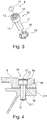
- the screw 9 ( Fig. 3 ) a screw 10 with a screw shaft 11 and a screw head 12, which has a hexagonal recess 13.
- the thread on the screw shaft 11 is not shown in detail, but with 12.1 in Fig. 4 located.
- the screw 10 is to be screwed into a metal insert 2.1 of the door 2.
- On its outer peripheral surface of the screw head 12 is formed smooth, but has on its underside a locking teeth 14.
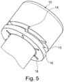
- This ratchet 14 is also closer to Fig. 4 and Fig. 5 refer to.
- This locking toothing 14 of the screw head 12 cooperates with a further locking toothing 15, which is provided on the washer 16.
- the locking teeth 15 and 14, in the mounted state ( Fig. 4 ) lie on top of each other, interact directly.
- a safety ball 17 is pressed, which can additionally or alternatively also be glued after the assembly or screwing of the hinge was made.
- Fig. 5 is still provided on the washer 16 with the teeth 15 a ribbing 18 in the form of web-like ribs, which press in the assembly of the screw 10 and the washer 16 in the upper of the door 2.
Landscapes
- Engineering & Computer Science (AREA)
- Mechanical Engineering (AREA)
- General Engineering & Computer Science (AREA)
- Hinges (AREA)
- Body Structure For Vehicles (AREA)
Abstract
Description
- Die Erfindung bezieht sich auf einen Nutzfahrzeugaufbau mit Seitenwandungen, einer Stirnwand, einer Heckwand sowie mit zumindest einer über Türscharniere schwenkbewegliche, insbesondere in der Heckwand angeordneten Tür zur Begrenzung eines Laderaumes, wobei die Tür über die Türscharniere an einem Wandungsteil des Fahrzeugaufbaus festgelegt ist.
- Türen von Nutzfahrzeugaufbauten, wie beispielsweise Türen von wärmegedämmten Sattelanhängern und Wechselkoffern, sind während einer Transportfahrt des Fahrzeuges zollsicher zu verschließen. Herkömmlicherweise wird dies durch eine Zollsicherungsausrüstung der Befestigung von Türscharnieren dadurch erzielt, indem eine formschlüssige Schweißverbindung vorgesehen ist. Dabei wird an einem Schraubenkopf einer Schraubverbindung zur Befestigung der Türscharniere an einem Wandungsteil ein Schweißpunkt oder eine Schweißnaht angebracht, der bzw. die eine Verdrehung der Schraube nach der Montage des Türscharniers an dem Wandungsteil verhindert. Das Verschweißen des Schraubenkopfes während eines Montagevorganges verursacht jedoch zusätzliche Arbeitsgänge und ist mithin montageaufwändig. Zudem führt die Verbindung unterschiedlicher Metalle zu elektrochemischen Spannungen und damit zu Korrosionserscheinungen. Des Weiteren erfordert ein Schweißvorgang einen nicht unerheblichen Aufwand an Nachbearbeitungsvorgängen während der Montage und macht eine Reinigung des Schweißbereiches notwendig. Zudem stellt die Fertigung einer Schweißverbindung bei der Montage eines Nutzfahrzeugaufbaus einen eher untypischen Fertigungsschritt dar, der die Bereitstellung entsprechender Schweißwerkzeuge und die Bereitstellung von entsprechendem geschulten Personal notwendig macht.
- Es ist Aufgabe der vorliegenden Erfindung, einen Nutzfahrzeugaufbau zur Verfügung zu stellen mit einer zollsicheren Befestigung einer Tür an einem Wandungsteil des Nutzfahrzeugaufbaus, die den Anforderungen des Leitfadens "Zollsichere Herrichtung von Straßenfahrzeugen und Behältern mit wärmegedämmtem Aufbau" entspricht, jedoch in montagefreundlicher Weise realisiert werden kann.
- Zur Lösung dieser Aufgabe zeichnet sich der Nutzfahrzeugaufbau der eingangs genannten Art dadurch aus, dass ein Türscharnier der Tür über eine Schraubverbindung mit einem Wandungsteil des Nutzfahrzeugaufbaus verbunden ist und dass die Schraubverbindung eine Schraube mit einem Schraubenkopf und mit einer daran vorgesehenen Sperrverzahnung und mit einer Unterlegscheibe mit einer weiteren Sperrverzahnung umfasst, wobei die Sperrverzahnung der Schraube und die Sperrverzahnung der Unterlegscheibe einander zugewandt zusammenwirken.
- Damit ist eine Verbindung des Türscharniers mit einem Wandungsteil des Nutzfahrzeugaufbaus möglich, bei denen über die Schraube und die Unterlegscheibe über die jeweiligen Sperrverzahnungen eine Zollverschraubung mit Rastgeometrie verwirklicht ist, die im Rahmen einer üblichen Montage eines Nutzfahrzeugaufbaus mit Türscharnieren und einer Tür erfolgen kann. Dazu erfordert es lediglich die Werkzeuge, die üblicherweise bei der Montage eines Nutzfahrzeugaufbaus bereitzustellen sind.
- Eine Kombination verschiedener Metallwerkstoffe ist hierbei durchaus möglich und führt zu keinerlei besonderen Nachbearbeitungen bzw. zu späteren Korrosionserscheinungen.
- Bei einer Montage z.B. einer Türschraube mit Unterlegscheibe wird die Unterlegscheibe, z.B. insbesondere dann, wenn auf der im Wandungsteil bzw. dem Türscharnier zugewandten Seite der Unterlegscheibe eine Verrippung vorgesehen ist, in die Oberfläche des darunter liegenden Materials, beispielsweise des Türflügels eingedrückt, womit eine weitere Verdrehung der Scheibe, insbesondere ein Rückdrehen, verhindert ist. Durch die Sperrverzahnung, bei der die Sperrklinken in eine Drehrichtung wirken, ist sichergestellt, dass auch der Schraubenkopf nach der Montage nicht verdreht werden kann.
- Durch die zusätzliche Sicherungskugel, die vorzugsweise mittels einer Pressverbindung in die Innensechskantausnehmung dauerhaft eingebracht ist, ist eine unbemerkte Demontage der Schraube nahezu unmöglich. Auf alle Fälle ist sichergestellt, dass der Versuch einer Demontage der Schraube einer Zerstörung der Schraube gleichkommt, was optisch sofort wahrnehmbar wäre und im Übrigen auch einen entsprechenden Zeitaufwand verursachen würde, um die Zerstörung der Schraube vorzunehmen. Damit ist den Anforderungen des Leitfadens "Zollsichere Herrichtung von Straßenfahrzeugen und Behältern mit wärmegedämmtem Aufbau" voll entsprochen, gleichwohl jedoch der Herstellungs- und Montageaufwand für diese zollsichere Befestigung von Türscharnieren an Nutzfahrzeugaufbauten, insbesondere auch an wärmegedämmten Sattelanhängern und Wechselkoffern, wesentlich verringert.
- Zur weiteren Erläuterung der Erfindung wird auf weitere Ansprüche, die nachfolgende Beschreibung und die Zeichnung verwiesen. In der Zeichnung zeigen:
- Fig. 1
- ausschnittsweise eine perspektivische Ansicht des Heckbereiches eines Ausführungsbeispiels eines Nutzfahrzeugaufbaus mit einer aufschwenkbaren Doppeltür;
- Fig. 2
- eine vergrößerte Ansicht des Ausführungsbeispiels nach
Fig. 1 im Bereich des Hecktürscharniers; - Fig. 3
- in Einzeldarstellung perspektivisch eine Schraube mit Unterlegscheibe und Sicherungskugel des Ausführungsbeispiels nach
Fig. 1 ; - Fig. 4
- die Teile nach
Fig. 3 im montierten Zustand mit Darstellung des Scharnierflügels und der Hecktür, und - Fig. 5
- perspektivisch ausschnittsweise die Schraube mit der Unterlegscheibe vor einer Montage.
- In der Zeichnung sind grundsätzlich übereinstimmende Teile mit übereinstimmenden Bezugsziffern versehen.
-
Fig. 1 zeigt die Heckwand 1 eines ansonsten nicht näher dargestellten Ausführungsbeispiels eines Nutzfahrzeugaufbaus, die zwei Türen 2 und 3 aufweist, die über Türscharniere 4 aufzuschwenken sind. Diese Türscharniere 4 sind an Rahmenteilen 5 befestigt. Die Türen 2 und 3 sind über Sperrstangen 6 zu verriegeln nach entsprechender Betätigung von Hebeln 7. Die Türen 2 und 3 selber weisen noch Entlüftungsklappen 8 auf. - In
Fig. 2 ist ein Türscharnier 4 für die Tür 2 gezeigt, das insgesamt zwei Reihen von Bohrungen aufweist mit jeweils drei Bohrungen, in die eine Schraubverbindung einzuführen ist, um den Flügel des Türscharniers 4 mit der Tür 2 zu verbinden. - Dazu weist die Schraubverbindung 9 (
Fig. 3 ) eine Schraube 10 auf mit einem Schraubenschaft 11 und einem Schraubenkopf 12, der eine Innensechskantausnehmung 13 aufweist. Das Gewinde am Schraubenschaft 11 ist nicht näher dargestellt, sondern mit 12.1 inFig. 4 eingezeichnet. Die Schraube 10 ist in eine Metalleinlage 2.1 der Tür 2 einzuschrauben. An seiner Außenumfangfläche ist der Schraubenkopf 12 glatt ausgebildet, hat jedoch an seiner Unterseite eine Sperrverzahnung 14. Diese Sperrverzahnung 14 ist auch näher denFig. 4 undFig. 5 zu entnehmen. Diese Sperrverzahnung 14 des Schraubenkopfes 12 wirkt zusammen mit einer weiteren Sperrverzahnung 15, die an der Unterlegscheibe 16 vorgesehen ist. Die Sperrverzahnungen 15 und 14, die im montierten Zustand (Fig. 4 ) aufeinanderliegen, wirken unmittelbar zusammen. - In die Innensechskantausnehmung 13 ist eine Sicherungskugel 17 einzupressen, die zusätzlich oder alternativ auch noch eingeklebt werden kann, nachdem die Montage bzw. Verschraubung des Scharniers vorgenommen wurde.
- Wie
Fig. 5 zu entnehmen ist, ist an der Unterlegscheibe 16 mit der Verzahnung 15 noch eine Verrippung 18 in Gestalt von stegartigen Rippen vorgesehen, die sich bei der Montage der Schraube 10 und der Unterlegscheibe 16 in das Obermaterial der Tür 2 hineindrücken.
Claims (9)
- Nutzfahrzeugaufbau mit Seitenwandungen, einer Stirnwand, einer Heckwand sowie mit zumindest einer über Türscharniere (4) schwenkbeweglichen, insbesondere in der Heckwand angeordneten Tür (2, 3) zur Begrenzung eines Laderaumes, wobei die Tür (2, 3) über zumindest ein Türscharnier (4) an einem Aufbauteil des Fahrzeugaufbaus festgelegt, dadurch gekennzeichnet, dass ein Türscharnier (4) der Tür (2, 3) über eine Schraubverbindung mit einem Aufbauteil des Nutzfahrzeugaufbaus verbunden ist und dass die Schraubverbindung eine Schraube (10) mit einem Schraubenkopf (12) mit einer daran vorgesehenen Sperrverzahnung (14) und mit einer Unterlegscheibe (16) mit einer weiteren Sperrverzahnung (15) umfasst, wobei die Sperrverzahnung (14) der Schraube (10) und die Sperrverzahnung (15) der Unterlegscheibe (16) einander zugewandt zusammenwirken.
- Nutzfahrzeugaufbau nach Anspruch 1, dadurch gekennzeichnet, dass die Schraube (10) der Schraubverbindung eine an einem Schraubenschaft (11) vorgesehenes Außengewinde (12.1) aufweist und in die Tür (2, 3) oder in eine Einlage (2.1) der Tür (2, 3) des Nutzfahrzeugaufbaus einschraubbar ist.
- Nutzfahrzeugaufbau nach Anspruch 1 oder 2, dadurch gekennzeichnet, dass der Schraubenkopf (12) einen ringförmigen glatten Außenbereich aufweist und eine Ausnehmung (13) zum Einführen eines Montagewerkzeuges aufweist, wobei die Ausnehmung (13) durch eine verliersicher eingebrachte Sicherungskugel (17) die Schraube (16) gegen eine Demontage sichert.
- Nutzfahrzeugaufbau nach Anspruch 3, dadurch gekennzeichnet, dass die Sicherungskugel (17) verliersicher in die Ausnehmung (13) eingepresst ist.
- Nutzfahrzeugaufbau nach einem der Ansprüche 1 bis 4, dadurch gekennzeichnet, dass die Unterlegscheibe (16) an ihrer der Sperrverzahnung (15) gegenüberliegenden, dem Türscharnier (4) zugewandten Auflagefläche eine Verrippung (18) aufweist.
- Nutzfahrzeugaufbau nach Anspruch 5, dadurch gekennzeichnet, dass die Verrippung (18) durch mit Abstand zueinander vorgesehene Stege im Verlaufe der Montage der Schraube (10) in den Werkstoff des Türscharniers (4) eindrückbar ist.
- Nutzfahrzeugaufbau nach einem der Ansprüche 1 bis 6, dadurch gekennzeichnet, dass die Tür (2, 3) des Nutzfahrzeugaufbaus eine Einlage (2.1) aufweist, in die ein Scharnierflügel des Türscharniers (4) eingebracht ist.
- Nutzfahrzeug nach einem der Ansprüche 1 bis 7, dadurch gekennzeichnet, dass die Schraube (10) und/oder die Unterlegscheibe (16) aus unterschiedlichen Metallwerkstoffen bestehen.
- Nutzfahrzeugaufbau nach einem der Ansprüche 3 bis 8, dadurch gekennzeichnet, dass die Sicherungskugel (17) in der Ausnehmung (13) durch Verpressen gegen ein unbemerktes Lösen gesichert ist.
Applications Claiming Priority (1)
| Application Number | Priority Date | Filing Date | Title |
|---|---|---|---|
| DE102016000910.1A DE102016000910A1 (de) | 2016-01-29 | 2016-01-29 | Nutzfahrzeugaufbau |
Publications (2)
| Publication Number | Publication Date |
|---|---|
| EP3199394A1 true EP3199394A1 (de) | 2017-08-02 |
| EP3199394B1 EP3199394B1 (de) | 2023-07-05 |
Family
ID=57208040
Family Applications (1)
| Application Number | Title | Priority Date | Filing Date |
|---|---|---|---|
| EP16002273.7A Active EP3199394B1 (de) | 2016-01-29 | 2016-10-25 | Nutzfahrzeugaufbau |
Country Status (5)
| Country | Link |
|---|---|
| EP (1) | EP3199394B1 (de) |
| DE (1) | DE102016000910A1 (de) |
| DK (1) | DK3199394T3 (de) |
| ES (1) | ES2959268T3 (de) |
| PL (1) | PL3199394T3 (de) |
Families Citing this family (1)
| Publication number | Priority date | Publication date | Assignee | Title |
|---|---|---|---|---|
| DE102018132206B3 (de) | 2018-12-14 | 2020-06-18 | Kögel Trailer GmbH | Scharniersystem, Fahrzeugaufbau, Fahrzeug und Verfahren zur Montage einer Türe |
Citations (6)
| Publication number | Priority date | Publication date | Assignee | Title |
|---|---|---|---|---|
| US3263727A (en) * | 1964-09-23 | 1966-08-02 | Arthur B Herpolsheimer | Lock washer arrangement |
| US3926237A (en) * | 1972-03-30 | 1975-12-16 | Max L Enders | Self-locking vibration-proof lock washer and cooperating threaded fastener |
| DE202007008534U1 (de) * | 2007-06-14 | 2007-08-30 | Hema-Zaunsysteme Gmbh | Sicherheitsschraube |
| JP2008230393A (ja) * | 2007-03-20 | 2008-10-02 | Topre Corp | 保冷庫用ドアのヒンジ取付部材及びヒンジ取付構造 |
| DE102010017605A1 (de) * | 2010-06-25 | 2011-12-29 | Wihag Fahrzeugbausysteme Gmbh | Fahrzeughecktür |
| JP2012071822A (ja) * | 2010-09-02 | 2012-04-12 | Nippon Fruehauf Co Ltd | 跳ね上げ扉の開閉装置 |
Family Cites Families (6)
| Publication number | Priority date | Publication date | Assignee | Title |
|---|---|---|---|---|
| US5964499A (en) * | 1996-02-28 | 1999-10-12 | Great Dane Limited Partnership | Door-mounted gasket for comb-type rear frame |
| DE10048913B4 (de) * | 2000-10-04 | 2005-03-24 | Kamax-Werke Rudolf Kellermann Gmbh & Co. Kg | Lösbares Verbindungselement für ein Bauteil, mit einem Schraubteil und einem Sicherungsring |
| DE10053372C1 (de) * | 2000-10-27 | 2002-01-31 | Schmitz Cargobull Ag | Türblatt mir Scharnier für den Aufbau eines Lastfahrzeuges sowie Lagerplatte für ein solches Scharnier |
| DE10205300C1 (de) * | 2002-02-08 | 2003-09-25 | Kellermann Fa Rudolf | Lösbares Verbindungselement für ein Bauteil mit einem Schrabteil und einem Sicherungsring |
| DE102009022939A1 (de) * | 2009-05-27 | 2010-12-02 | Audi Ag | Kraftfahrzeug mit einer höheneinstellbaren Frontklappe |
| DE202011105266U1 (de) * | 2011-09-02 | 2011-12-22 | E. Winkemann Gmbh & Co. Kg | Sicherungsscheibe |
-
2016
- 2016-01-29 DE DE102016000910.1A patent/DE102016000910A1/de active Pending
- 2016-10-25 EP EP16002273.7A patent/EP3199394B1/de active Active
- 2016-10-25 DK DK16002273.7T patent/DK3199394T3/da active
- 2016-10-25 ES ES16002273T patent/ES2959268T3/es active Active
- 2016-10-25 PL PL16002273.7T patent/PL3199394T3/pl unknown
Patent Citations (6)
| Publication number | Priority date | Publication date | Assignee | Title |
|---|---|---|---|---|
| US3263727A (en) * | 1964-09-23 | 1966-08-02 | Arthur B Herpolsheimer | Lock washer arrangement |
| US3926237A (en) * | 1972-03-30 | 1975-12-16 | Max L Enders | Self-locking vibration-proof lock washer and cooperating threaded fastener |
| JP2008230393A (ja) * | 2007-03-20 | 2008-10-02 | Topre Corp | 保冷庫用ドアのヒンジ取付部材及びヒンジ取付構造 |
| DE202007008534U1 (de) * | 2007-06-14 | 2007-08-30 | Hema-Zaunsysteme Gmbh | Sicherheitsschraube |
| DE102010017605A1 (de) * | 2010-06-25 | 2011-12-29 | Wihag Fahrzeugbausysteme Gmbh | Fahrzeughecktür |
| JP2012071822A (ja) * | 2010-09-02 | 2012-04-12 | Nippon Fruehauf Co Ltd | 跳ね上げ扉の開閉装置 |
Also Published As
| Publication number | Publication date |
|---|---|
| ES2959268T3 (es) | 2024-02-22 |
| EP3199394B1 (de) | 2023-07-05 |
| DE102016000910A1 (de) | 2017-08-03 |
| DK3199394T3 (da) | 2023-10-09 |
| PL3199394T3 (pl) | 2024-04-02 |
Similar Documents
| Publication | Publication Date | Title |
|---|---|---|
| DE4039472C2 (de) | Vorrichtung zum Sichern einer in einer Öffnung einer Verkleidung aufgenommenen Mutter | |
| DE4033763C2 (de) | Vorrichtung zum Sichern einer in einer Öffnung in einer Verkleidung aufgenommenen Mutter | |
| DE1944805A1 (de) | Verschraubung | |
| DE102005004000A1 (de) | Mitnehmer | |
| EP1961976A2 (de) | Befestigungseinheit | |
| EP2037131A1 (de) | Hybridbauteil | |
| DE19949545B4 (de) | Zahnriemen zum Transportieren von Objekten | |
| DE19742766A1 (de) | Schließkloben für eine Kraftfahrzeug-Schließeinrichtung | |
| EP1319584A1 (de) | Kippmulde für ein Transportfahrzeug und Verfahren zur Herstellung von Kippmulden | |
| DE19715496C1 (de) | Justierelement | |
| DE102006033995B4 (de) | Abdeckung für eine Radlagerung, Radnabe, Abdeckkappe und Abdeckung | |
| EP3199394A1 (de) | Nutzfahrzeugaufbau | |
| DE102007040041A1 (de) | Verbindungsanordnung zur Verschiebesicherung eines Fahrzeuganbauteils und zugehörige Befestigungsanordnung für ein Fahrzeuganbauteil | |
| EP2955301A1 (de) | Behälterschloss | |
| DE9206646U1 (de) | Schraubverbindung von Kunststoff-Hohlprofilen | |
| DE202017105765U1 (de) | Befestigungsvorrichtung zur Befestigung von mindestens einem Bauteil | |
| DE3905688C2 (de) | ||
| DE202004004407U1 (de) | Zug-Druck-Stange | |
| DE102017100821B4 (de) | Anhängekupplung mit Kippsicherung | |
| DE20303884U1 (de) | Befestigungseinrichtung für eine Plane | |
| DE19612619C2 (de) | Verfahren zur Herstellung einer Lochverstärkung in einem Blech mittels einer Scheibe, sowie Lochverstärkung | |
| DE102008005744B3 (de) | Befestigungseinrichtung für Fensterhebermodule | |
| EP3305568B1 (de) | Ratschenspannvorrichtung sowie adapterteil für eine aufwickelwelle für eine lkw-verkleidung | |
| EP2933140B1 (de) | Sicherungsschiene zum einbau in fahrzeuge | |
| EP2218657B1 (de) | Planenaufbau eines Nutzfahrzeugs |
Legal Events
| Date | Code | Title | Description |
|---|---|---|---|
| PUAI | Public reference made under article 153(3) epc to a published international application that has entered the european phase |
Free format text: ORIGINAL CODE: 0009012 |
|
| STAA | Information on the status of an ep patent application or granted ep patent |
Free format text: STATUS: THE APPLICATION HAS BEEN PUBLISHED |
|
| AK | Designated contracting states |
Kind code of ref document: A1 Designated state(s): AL AT BE BG CH CY CZ DE DK EE ES FI FR GB GR HR HU IE IS IT LI LT LU LV MC MK MT NL NO PL PT RO RS SE SI SK SM TR |
|
| AX | Request for extension of the european patent |
Extension state: BA ME |
|
| STAA | Information on the status of an ep patent application or granted ep patent |
Free format text: STATUS: REQUEST FOR EXAMINATION WAS MADE |
|
| 17P | Request for examination filed |
Effective date: 20171005 |
|
| RBV | Designated contracting states (corrected) |
Designated state(s): AL AT BE BG CH CY CZ DE DK EE ES FI FR GB GR HR HU IE IS IT LI LT LU LV MC MK MT NL NO PL PT RO RS SE SI SK SM TR |
|
| STAA | Information on the status of an ep patent application or granted ep patent |
Free format text: STATUS: EXAMINATION IS IN PROGRESS |
|
| 17Q | First examination report despatched |
Effective date: 20181009 |
|
| STAA | Information on the status of an ep patent application or granted ep patent |
Free format text: STATUS: EXAMINATION IS IN PROGRESS |
|
| APBK | Appeal reference recorded |
Free format text: ORIGINAL CODE: EPIDOSNREFNE |
|
| APBN | Date of receipt of notice of appeal recorded |
Free format text: ORIGINAL CODE: EPIDOSNNOA2E |
|
| APBR | Date of receipt of statement of grounds of appeal recorded |
Free format text: ORIGINAL CODE: EPIDOSNNOA3E |
|
| APAF | Appeal reference modified |
Free format text: ORIGINAL CODE: EPIDOSCREFNE |
|
| APBT | Appeal procedure closed |
Free format text: ORIGINAL CODE: EPIDOSNNOA9E |
|
| GRAP | Despatch of communication of intention to grant a patent |
Free format text: ORIGINAL CODE: EPIDOSNIGR1 |
|
| STAA | Information on the status of an ep patent application or granted ep patent |
Free format text: STATUS: GRANT OF PATENT IS INTENDED |
|
| INTG | Intention to grant announced |
Effective date: 20230131 |
|
| GRAS | Grant fee paid |
Free format text: ORIGINAL CODE: EPIDOSNIGR3 |
|
| GRAA | (expected) grant |
Free format text: ORIGINAL CODE: 0009210 |
|
| STAA | Information on the status of an ep patent application or granted ep patent |
Free format text: STATUS: THE PATENT HAS BEEN GRANTED |
|
| AK | Designated contracting states |
Kind code of ref document: B1 Designated state(s): AL AT BE BG CH CY CZ DE DK EE ES FI FR GB GR HR HU IE IS IT LI LT LU LV MC MK MT NL NO PL PT RO RS SE SI SK SM TR |
|
| REG | Reference to a national code |
Ref country code: CH Ref legal event code: EP |
|
| REG | Reference to a national code |
Ref country code: AT Ref legal event code: REF Ref document number: 1584538 Country of ref document: AT Kind code of ref document: T Effective date: 20230715 |
|
| REG | Reference to a national code |
Ref country code: DE Ref legal event code: R096 Ref document number: 502016015906 Country of ref document: DE |
|
| P01 | Opt-out of the competence of the unified patent court (upc) registered |
Effective date: 20230626 |
|
| REG | Reference to a national code |
Ref country code: IE Ref legal event code: FG4D Free format text: LANGUAGE OF EP DOCUMENT: GERMAN |
|
| REG | Reference to a national code |
Ref country code: DK Ref legal event code: T3 Effective date: 20231003 |
|
| REG | Reference to a national code |
Ref country code: NL Ref legal event code: FP |
|
| REG | Reference to a national code |
Ref country code: SE Ref legal event code: TRGR |
|
| REG | Reference to a national code |
Ref country code: LT Ref legal event code: MG9D |
|
| PGFP | Annual fee paid to national office [announced via postgrant information from national office to epo] |
Ref country code: TR Payment date: 20230929 Year of fee payment: 8 Ref country code: GB Payment date: 20230928 Year of fee payment: 8 |
|
| PGFP | Annual fee paid to national office [announced via postgrant information from national office to epo] |
Ref country code: NL Payment date: 20231020 Year of fee payment: 8 |
|
| PG25 | Lapsed in a contracting state [announced via postgrant information from national office to epo] |
Ref country code: GR Free format text: LAPSE BECAUSE OF FAILURE TO SUBMIT A TRANSLATION OF THE DESCRIPTION OR TO PAY THE FEE WITHIN THE PRESCRIBED TIME-LIMIT Effective date: 20231006 |
|
| PGFP | Annual fee paid to national office [announced via postgrant information from national office to epo] |
Ref country code: ES Payment date: 20231102 Year of fee payment: 8 |
|
| PG25 | Lapsed in a contracting state [announced via postgrant information from national office to epo] |
Ref country code: IS Free format text: LAPSE BECAUSE OF FAILURE TO SUBMIT A TRANSLATION OF THE DESCRIPTION OR TO PAY THE FEE WITHIN THE PRESCRIBED TIME-LIMIT Effective date: 20231105 |
|
| PG25 | Lapsed in a contracting state [announced via postgrant information from national office to epo] |
Ref country code: RS Free format text: LAPSE BECAUSE OF FAILURE TO SUBMIT A TRANSLATION OF THE DESCRIPTION OR TO PAY THE FEE WITHIN THE PRESCRIBED TIME-LIMIT Effective date: 20230705 Ref country code: PT Free format text: LAPSE BECAUSE OF FAILURE TO SUBMIT A TRANSLATION OF THE DESCRIPTION OR TO PAY THE FEE WITHIN THE PRESCRIBED TIME-LIMIT Effective date: 20231106 Ref country code: NO Free format text: LAPSE BECAUSE OF FAILURE TO SUBMIT A TRANSLATION OF THE DESCRIPTION OR TO PAY THE FEE WITHIN THE PRESCRIBED TIME-LIMIT Effective date: 20231005 Ref country code: LV Free format text: LAPSE BECAUSE OF FAILURE TO SUBMIT A TRANSLATION OF THE DESCRIPTION OR TO PAY THE FEE WITHIN THE PRESCRIBED TIME-LIMIT Effective date: 20230705 Ref country code: LT Free format text: LAPSE BECAUSE OF FAILURE TO SUBMIT A TRANSLATION OF THE DESCRIPTION OR TO PAY THE FEE WITHIN THE PRESCRIBED TIME-LIMIT Effective date: 20230705 Ref country code: IS Free format text: LAPSE BECAUSE OF FAILURE TO SUBMIT A TRANSLATION OF THE DESCRIPTION OR TO PAY THE FEE WITHIN THE PRESCRIBED TIME-LIMIT Effective date: 20231105 Ref country code: HR Free format text: LAPSE BECAUSE OF FAILURE TO SUBMIT A TRANSLATION OF THE DESCRIPTION OR TO PAY THE FEE WITHIN THE PRESCRIBED TIME-LIMIT Effective date: 20230705 Ref country code: GR Free format text: LAPSE BECAUSE OF FAILURE TO SUBMIT A TRANSLATION OF THE DESCRIPTION OR TO PAY THE FEE WITHIN THE PRESCRIBED TIME-LIMIT Effective date: 20231006 Ref country code: FI Free format text: LAPSE BECAUSE OF FAILURE TO SUBMIT A TRANSLATION OF THE DESCRIPTION OR TO PAY THE FEE WITHIN THE PRESCRIBED TIME-LIMIT Effective date: 20230705 |
|
| PGFP | Annual fee paid to national office [announced via postgrant information from national office to epo] |
Ref country code: IT Payment date: 20231006 Year of fee payment: 8 Ref country code: FR Payment date: 20231023 Year of fee payment: 8 Ref country code: DK Payment date: 20231010 Year of fee payment: 8 Ref country code: DE Payment date: 20231026 Year of fee payment: 8 Ref country code: AT Payment date: 20231011 Year of fee payment: 8 |
|
| REG | Reference to a national code |
Ref country code: ES Ref legal event code: FG2A Ref document number: 2959268 Country of ref document: ES Kind code of ref document: T3 Effective date: 20240222 |
|
| PGFP | Annual fee paid to national office [announced via postgrant information from national office to epo] |
Ref country code: BE Payment date: 20231025 Year of fee payment: 8 |
|
| REG | Reference to a national code |
Ref country code: DE Ref legal event code: R097 Ref document number: 502016015906 Country of ref document: DE |
|
| PG25 | Lapsed in a contracting state [announced via postgrant information from national office to epo] |
Ref country code: SM Free format text: LAPSE BECAUSE OF FAILURE TO SUBMIT A TRANSLATION OF THE DESCRIPTION OR TO PAY THE FEE WITHIN THE PRESCRIBED TIME-LIMIT Effective date: 20230705 Ref country code: RO Free format text: LAPSE BECAUSE OF FAILURE TO SUBMIT A TRANSLATION OF THE DESCRIPTION OR TO PAY THE FEE WITHIN THE PRESCRIBED TIME-LIMIT Effective date: 20230705 Ref country code: EE Free format text: LAPSE BECAUSE OF FAILURE TO SUBMIT A TRANSLATION OF THE DESCRIPTION OR TO PAY THE FEE WITHIN THE PRESCRIBED TIME-LIMIT Effective date: 20230705 Ref country code: CZ Free format text: LAPSE BECAUSE OF FAILURE TO SUBMIT A TRANSLATION OF THE DESCRIPTION OR TO PAY THE FEE WITHIN THE PRESCRIBED TIME-LIMIT Effective date: 20230705 Ref country code: SK Free format text: LAPSE BECAUSE OF FAILURE TO SUBMIT A TRANSLATION OF THE DESCRIPTION OR TO PAY THE FEE WITHIN THE PRESCRIBED TIME-LIMIT Effective date: 20230705 |
|
| PLBE | No opposition filed within time limit |
Free format text: ORIGINAL CODE: 0009261 |
|
| STAA | Information on the status of an ep patent application or granted ep patent |
Free format text: STATUS: NO OPPOSITION FILED WITHIN TIME LIMIT |
|
| PG25 | Lapsed in a contracting state [announced via postgrant information from national office to epo] |
Ref country code: MC Free format text: LAPSE BECAUSE OF FAILURE TO SUBMIT A TRANSLATION OF THE DESCRIPTION OR TO PAY THE FEE WITHIN THE PRESCRIBED TIME-LIMIT Effective date: 20230705 |
|
| PGFP | Annual fee paid to national office [announced via postgrant information from national office to epo] |
Ref country code: PL Payment date: 20230918 Year of fee payment: 8 |
|
| REG | Reference to a national code |
Ref country code: CH Ref legal event code: PL |
|
| 26N | No opposition filed |
Effective date: 20240408 |
|
| PG25 | Lapsed in a contracting state [announced via postgrant information from national office to epo] |
Ref country code: LU Free format text: LAPSE BECAUSE OF NON-PAYMENT OF DUE FEES Effective date: 20231025 |
|
| PG25 | Lapsed in a contracting state [announced via postgrant information from national office to epo] |
Ref country code: LU Free format text: LAPSE BECAUSE OF NON-PAYMENT OF DUE FEES Effective date: 20231025 |
|
| PG25 | Lapsed in a contracting state [announced via postgrant information from national office to epo] |
Ref country code: CH Free format text: LAPSE BECAUSE OF NON-PAYMENT OF DUE FEES Effective date: 20231031 |
|
| PG25 | Lapsed in a contracting state [announced via postgrant information from national office to epo] |
Ref country code: CH Free format text: LAPSE BECAUSE OF NON-PAYMENT OF DUE FEES Effective date: 20231031 Ref country code: SI Free format text: LAPSE BECAUSE OF FAILURE TO SUBMIT A TRANSLATION OF THE DESCRIPTION OR TO PAY THE FEE WITHIN THE PRESCRIBED TIME-LIMIT Effective date: 20230705 |