EP3197968B1 - Method for producing a cladding for elongated material - Google Patents
Method for producing a cladding for elongated material Download PDFInfo
- Publication number
- EP3197968B1 EP3197968B1 EP15759691.7A EP15759691A EP3197968B1 EP 3197968 B1 EP3197968 B1 EP 3197968B1 EP 15759691 A EP15759691 A EP 15759691A EP 3197968 B1 EP3197968 B1 EP 3197968B1
- Authority
- EP
- European Patent Office
- Prior art keywords
- adhesive
- carrier
- tape
- coating
- adhesive tape
- Prior art date
- Legal status (The legal status is an assumption and is not a legal conclusion. Google has not performed a legal analysis and makes no representation as to the accuracy of the status listed.)
- Active
Links
- 238000004519 manufacturing process Methods 0.000 title claims description 15
- 239000000463 material Substances 0.000 title description 27
- 238000005253 cladding Methods 0.000 title 1
- 238000000576 coating method Methods 0.000 claims description 108
- 239000000853 adhesive Substances 0.000 claims description 107
- 230000001070 adhesive effect Effects 0.000 claims description 107
- 239000011248 coating agent Substances 0.000 claims description 100
- 239000002390 adhesive tape Substances 0.000 claims description 91
- 238000000034 method Methods 0.000 claims description 20
- 238000004804 winding Methods 0.000 claims description 3
- 239000006228 supernatant Substances 0.000 description 36
- 239000000047 product Substances 0.000 description 13
- 238000012546 transfer Methods 0.000 description 6
- 239000004744 fabric Substances 0.000 description 5
- 239000011888 foil Substances 0.000 description 5
- 239000004753 textile Substances 0.000 description 5
- 238000013461 design Methods 0.000 description 4
- 239000002184 metal Substances 0.000 description 4
- 239000003973 paint Substances 0.000 description 3
- 239000012876 carrier material Substances 0.000 description 2
- 239000006260 foam Substances 0.000 description 2
- 229920000139 polyethylene terephthalate Polymers 0.000 description 2
- 239000005020 polyethylene terephthalate Substances 0.000 description 2
- 238000005507 spraying Methods 0.000 description 2
- NIXOWILDQLNWCW-UHFFFAOYSA-M Acrylate Chemical compound [O-]C(=O)C=C NIXOWILDQLNWCW-UHFFFAOYSA-M 0.000 description 1
- 239000004831 Hot glue Substances 0.000 description 1
- 239000004952 Polyamide Substances 0.000 description 1
- 239000004721 Polyphenylene oxide Substances 0.000 description 1
- 230000002730 additional effect Effects 0.000 description 1
- 238000012937 correction Methods 0.000 description 1
- 238000007766 curtain coating Methods 0.000 description 1
- 238000005520 cutting process Methods 0.000 description 1
- 238000010292 electrical insulation Methods 0.000 description 1
- 230000002349 favourable effect Effects 0.000 description 1
- 239000007888 film coating Substances 0.000 description 1
- 238000009501 film coating Methods 0.000 description 1
- 238000007759 kiss coating Methods 0.000 description 1
- 230000005923 long-lasting effect Effects 0.000 description 1
- 229920003052 natural elastomer Polymers 0.000 description 1
- 229920001194 natural rubber Polymers 0.000 description 1
- 239000004033 plastic Substances 0.000 description 1
- 229920003023 plastic Polymers 0.000 description 1
- 239000002985 plastic film Substances 0.000 description 1
- 229920006255 plastic film Polymers 0.000 description 1
- 229920002647 polyamide Polymers 0.000 description 1
- 229920000570 polyether Polymers 0.000 description 1
- -1 polyethylene terephthalate Polymers 0.000 description 1
- 229920001296 polysiloxane Polymers 0.000 description 1
- 229920002635 polyurethane Polymers 0.000 description 1
- 239000004814 polyurethane Substances 0.000 description 1
- 238000002360 preparation method Methods 0.000 description 1
- 238000012545 processing Methods 0.000 description 1
- 230000001681 protective effect Effects 0.000 description 1
- 230000005855 radiation Effects 0.000 description 1
- 238000009991 scouring Methods 0.000 description 1
- 238000005201 scrubbing Methods 0.000 description 1
- 229920003051 synthetic elastomer Polymers 0.000 description 1
- 239000005061 synthetic rubber Substances 0.000 description 1
- 230000007704 transition Effects 0.000 description 1
- 239000002759 woven fabric Substances 0.000 description 1
Images

Classifications
-
- B—PERFORMING OPERATIONS; TRANSPORTING
- B32—LAYERED PRODUCTS
- B32B—LAYERED PRODUCTS, i.e. PRODUCTS BUILT-UP OF STRATA OF FLAT OR NON-FLAT, e.g. CELLULAR OR HONEYCOMB, FORM
- B32B5/00—Layered products characterised by the non- homogeneity or physical structure, i.e. comprising a fibrous, filamentary, particulate or foam layer; Layered products characterised by having a layer differing constitutionally or physically in different parts
- B32B5/02—Layered products characterised by the non- homogeneity or physical structure, i.e. comprising a fibrous, filamentary, particulate or foam layer; Layered products characterised by having a layer differing constitutionally or physically in different parts characterised by structural features of a fibrous or filamentary layer
-
- B—PERFORMING OPERATIONS; TRANSPORTING
- B32—LAYERED PRODUCTS
- B32B—LAYERED PRODUCTS, i.e. PRODUCTS BUILT-UP OF STRATA OF FLAT OR NON-FLAT, e.g. CELLULAR OR HONEYCOMB, FORM
- B32B15/00—Layered products comprising a layer of metal
- B32B15/04—Layered products comprising a layer of metal comprising metal as the main or only constituent of a layer, which is next to another layer of the same or of a different material
- B32B15/08—Layered products comprising a layer of metal comprising metal as the main or only constituent of a layer, which is next to another layer of the same or of a different material of synthetic resin
-
- B—PERFORMING OPERATIONS; TRANSPORTING
- B32—LAYERED PRODUCTS
- B32B—LAYERED PRODUCTS, i.e. PRODUCTS BUILT-UP OF STRATA OF FLAT OR NON-FLAT, e.g. CELLULAR OR HONEYCOMB, FORM
- B32B15/00—Layered products comprising a layer of metal
- B32B15/04—Layered products comprising a layer of metal comprising metal as the main or only constituent of a layer, which is next to another layer of the same or of a different material
- B32B15/12—Layered products comprising a layer of metal comprising metal as the main or only constituent of a layer, which is next to another layer of the same or of a different material of paper or cardboard
-
- B—PERFORMING OPERATIONS; TRANSPORTING
- B32—LAYERED PRODUCTS
- B32B—LAYERED PRODUCTS, i.e. PRODUCTS BUILT-UP OF STRATA OF FLAT OR NON-FLAT, e.g. CELLULAR OR HONEYCOMB, FORM
- B32B15/00—Layered products comprising a layer of metal
- B32B15/14—Layered products comprising a layer of metal next to a fibrous or filamentary layer
-
- B—PERFORMING OPERATIONS; TRANSPORTING
- B32—LAYERED PRODUCTS
- B32B—LAYERED PRODUCTS, i.e. PRODUCTS BUILT-UP OF STRATA OF FLAT OR NON-FLAT, e.g. CELLULAR OR HONEYCOMB, FORM
- B32B27/00—Layered products comprising a layer of synthetic resin
- B32B27/06—Layered products comprising a layer of synthetic resin as the main or only constituent of a layer, which is next to another layer of the same or of a different material
- B32B27/08—Layered products comprising a layer of synthetic resin as the main or only constituent of a layer, which is next to another layer of the same or of a different material of synthetic resin
-
- B—PERFORMING OPERATIONS; TRANSPORTING
- B32—LAYERED PRODUCTS
- B32B—LAYERED PRODUCTS, i.e. PRODUCTS BUILT-UP OF STRATA OF FLAT OR NON-FLAT, e.g. CELLULAR OR HONEYCOMB, FORM
- B32B27/00—Layered products comprising a layer of synthetic resin
- B32B27/06—Layered products comprising a layer of synthetic resin as the main or only constituent of a layer, which is next to another layer of the same or of a different material
- B32B27/10—Layered products comprising a layer of synthetic resin as the main or only constituent of a layer, which is next to another layer of the same or of a different material of paper or cardboard
-
- B—PERFORMING OPERATIONS; TRANSPORTING
- B32—LAYERED PRODUCTS
- B32B—LAYERED PRODUCTS, i.e. PRODUCTS BUILT-UP OF STRATA OF FLAT OR NON-FLAT, e.g. CELLULAR OR HONEYCOMB, FORM
- B32B27/00—Layered products comprising a layer of synthetic resin
- B32B27/28—Layered products comprising a layer of synthetic resin comprising synthetic resins not wholly covered by any one of the sub-groups B32B27/30 - B32B27/42
- B32B27/283—Layered products comprising a layer of synthetic resin comprising synthetic resins not wholly covered by any one of the sub-groups B32B27/30 - B32B27/42 comprising polysiloxanes
-
- B—PERFORMING OPERATIONS; TRANSPORTING
- B32—LAYERED PRODUCTS
- B32B—LAYERED PRODUCTS, i.e. PRODUCTS BUILT-UP OF STRATA OF FLAT OR NON-FLAT, e.g. CELLULAR OR HONEYCOMB, FORM
- B32B27/00—Layered products comprising a layer of synthetic resin
- B32B27/28—Layered products comprising a layer of synthetic resin comprising synthetic resins not wholly covered by any one of the sub-groups B32B27/30 - B32B27/42
- B32B27/285—Layered products comprising a layer of synthetic resin comprising synthetic resins not wholly covered by any one of the sub-groups B32B27/30 - B32B27/42 comprising polyethers
-
- B—PERFORMING OPERATIONS; TRANSPORTING
- B32—LAYERED PRODUCTS
- B32B—LAYERED PRODUCTS, i.e. PRODUCTS BUILT-UP OF STRATA OF FLAT OR NON-FLAT, e.g. CELLULAR OR HONEYCOMB, FORM
- B32B27/00—Layered products comprising a layer of synthetic resin
- B32B27/30—Layered products comprising a layer of synthetic resin comprising vinyl (co)polymers; comprising acrylic (co)polymers
- B32B27/308—Layered products comprising a layer of synthetic resin comprising vinyl (co)polymers; comprising acrylic (co)polymers comprising acrylic (co)polymers
-
- B—PERFORMING OPERATIONS; TRANSPORTING
- B32—LAYERED PRODUCTS
- B32B—LAYERED PRODUCTS, i.e. PRODUCTS BUILT-UP OF STRATA OF FLAT OR NON-FLAT, e.g. CELLULAR OR HONEYCOMB, FORM
- B32B27/00—Layered products comprising a layer of synthetic resin
- B32B27/40—Layered products comprising a layer of synthetic resin comprising polyurethanes
-
- B—PERFORMING OPERATIONS; TRANSPORTING
- B32—LAYERED PRODUCTS
- B32B—LAYERED PRODUCTS, i.e. PRODUCTS BUILT-UP OF STRATA OF FLAT OR NON-FLAT, e.g. CELLULAR OR HONEYCOMB, FORM
- B32B29/00—Layered products comprising a layer of paper or cardboard
- B32B29/002—Layered products comprising a layer of paper or cardboard as the main or only constituent of a layer, which is next to another layer of the same or of a different material
-
- B—PERFORMING OPERATIONS; TRANSPORTING
- B32—LAYERED PRODUCTS
- B32B—LAYERED PRODUCTS, i.e. PRODUCTS BUILT-UP OF STRATA OF FLAT OR NON-FLAT, e.g. CELLULAR OR HONEYCOMB, FORM
- B32B29/00—Layered products comprising a layer of paper or cardboard
- B32B29/02—Layered products comprising a layer of paper or cardboard next to a fibrous or filamentary layer
-
- B—PERFORMING OPERATIONS; TRANSPORTING
- B32—LAYERED PRODUCTS
- B32B—LAYERED PRODUCTS, i.e. PRODUCTS BUILT-UP OF STRATA OF FLAT OR NON-FLAT, e.g. CELLULAR OR HONEYCOMB, FORM
- B32B37/00—Methods or apparatus for laminating, e.g. by curing or by ultrasonic bonding
- B32B37/12—Methods or apparatus for laminating, e.g. by curing or by ultrasonic bonding characterised by using adhesives
-
- B—PERFORMING OPERATIONS; TRANSPORTING
- B32—LAYERED PRODUCTS
- B32B—LAYERED PRODUCTS, i.e. PRODUCTS BUILT-UP OF STRATA OF FLAT OR NON-FLAT, e.g. CELLULAR OR HONEYCOMB, FORM
- B32B5/00—Layered products characterised by the non- homogeneity or physical structure, i.e. comprising a fibrous, filamentary, particulate or foam layer; Layered products characterised by having a layer differing constitutionally or physically in different parts
- B32B5/02—Layered products characterised by the non- homogeneity or physical structure, i.e. comprising a fibrous, filamentary, particulate or foam layer; Layered products characterised by having a layer differing constitutionally or physically in different parts characterised by structural features of a fibrous or filamentary layer
- B32B5/022—Non-woven fabric
-
- B—PERFORMING OPERATIONS; TRANSPORTING
- B32—LAYERED PRODUCTS
- B32B—LAYERED PRODUCTS, i.e. PRODUCTS BUILT-UP OF STRATA OF FLAT OR NON-FLAT, e.g. CELLULAR OR HONEYCOMB, FORM
- B32B5/00—Layered products characterised by the non- homogeneity or physical structure, i.e. comprising a fibrous, filamentary, particulate or foam layer; Layered products characterised by having a layer differing constitutionally or physically in different parts
- B32B5/02—Layered products characterised by the non- homogeneity or physical structure, i.e. comprising a fibrous, filamentary, particulate or foam layer; Layered products characterised by having a layer differing constitutionally or physically in different parts characterised by structural features of a fibrous or filamentary layer
- B32B5/024—Woven fabric
-
- B—PERFORMING OPERATIONS; TRANSPORTING
- B32—LAYERED PRODUCTS
- B32B—LAYERED PRODUCTS, i.e. PRODUCTS BUILT-UP OF STRATA OF FLAT OR NON-FLAT, e.g. CELLULAR OR HONEYCOMB, FORM
- B32B5/00—Layered products characterised by the non- homogeneity or physical structure, i.e. comprising a fibrous, filamentary, particulate or foam layer; Layered products characterised by having a layer differing constitutionally or physically in different parts
- B32B5/22—Layered products characterised by the non- homogeneity or physical structure, i.e. comprising a fibrous, filamentary, particulate or foam layer; Layered products characterised by having a layer differing constitutionally or physically in different parts characterised by the presence of two or more layers which are next to each other and are fibrous, filamentary, formed of particles or foamed
- B32B5/24—Layered products characterised by the non- homogeneity or physical structure, i.e. comprising a fibrous, filamentary, particulate or foam layer; Layered products characterised by having a layer differing constitutionally or physically in different parts characterised by the presence of two or more layers which are next to each other and are fibrous, filamentary, formed of particles or foamed one layer being a fibrous or filamentary layer
- B32B5/26—Layered products characterised by the non- homogeneity or physical structure, i.e. comprising a fibrous, filamentary, particulate or foam layer; Layered products characterised by having a layer differing constitutionally or physically in different parts characterised by the presence of two or more layers which are next to each other and are fibrous, filamentary, formed of particles or foamed one layer being a fibrous or filamentary layer another layer next to it also being fibrous or filamentary
-
- B—PERFORMING OPERATIONS; TRANSPORTING
- B32—LAYERED PRODUCTS
- B32B—LAYERED PRODUCTS, i.e. PRODUCTS BUILT-UP OF STRATA OF FLAT OR NON-FLAT, e.g. CELLULAR OR HONEYCOMB, FORM
- B32B7/00—Layered products characterised by the relation between layers; Layered products characterised by the relative orientation of features between layers, or by the relative values of a measurable parameter between layers, i.e. products comprising layers having different physical, chemical or physicochemical properties; Layered products characterised by the interconnection of layers
- B32B7/04—Interconnection of layers
- B32B7/05—Interconnection of layers the layers not being connected over the whole surface, e.g. discontinuous connection or patterned connection
-
- B—PERFORMING OPERATIONS; TRANSPORTING
- B32—LAYERED PRODUCTS
- B32B—LAYERED PRODUCTS, i.e. PRODUCTS BUILT-UP OF STRATA OF FLAT OR NON-FLAT, e.g. CELLULAR OR HONEYCOMB, FORM
- B32B7/00—Layered products characterised by the relation between layers; Layered products characterised by the relative orientation of features between layers, or by the relative values of a measurable parameter between layers, i.e. products comprising layers having different physical, chemical or physicochemical properties; Layered products characterised by the interconnection of layers
- B32B7/04—Interconnection of layers
- B32B7/12—Interconnection of layers using interposed adhesives or interposed materials with bonding properties
-
- C—CHEMISTRY; METALLURGY
- C09—DYES; PAINTS; POLISHES; NATURAL RESINS; ADHESIVES; COMPOSITIONS NOT OTHERWISE PROVIDED FOR; APPLICATIONS OF MATERIALS NOT OTHERWISE PROVIDED FOR
- C09J—ADHESIVES; NON-MECHANICAL ASPECTS OF ADHESIVE PROCESSES IN GENERAL; ADHESIVE PROCESSES NOT PROVIDED FOR ELSEWHERE; USE OF MATERIALS AS ADHESIVES
- C09J5/00—Adhesive processes in general; Adhesive processes not provided for elsewhere, e.g. relating to primers
- C09J5/04—Adhesive processes in general; Adhesive processes not provided for elsewhere, e.g. relating to primers involving separate application of adhesive ingredients to the different surfaces to be joined
-
- C—CHEMISTRY; METALLURGY
- C09—DYES; PAINTS; POLISHES; NATURAL RESINS; ADHESIVES; COMPOSITIONS NOT OTHERWISE PROVIDED FOR; APPLICATIONS OF MATERIALS NOT OTHERWISE PROVIDED FOR
- C09J—ADHESIVES; NON-MECHANICAL ASPECTS OF ADHESIVE PROCESSES IN GENERAL; ADHESIVE PROCESSES NOT PROVIDED FOR ELSEWHERE; USE OF MATERIALS AS ADHESIVES
- C09J7/00—Adhesives in the form of films or foils
- C09J7/20—Adhesives in the form of films or foils characterised by their carriers
- C09J7/29—Laminated material
-
- H—ELECTRICITY
- H01—ELECTRIC ELEMENTS
- H01B—CABLES; CONDUCTORS; INSULATORS; SELECTION OF MATERIALS FOR THEIR CONDUCTIVE, INSULATING OR DIELECTRIC PROPERTIES
- H01B13/00—Apparatus or processes specially adapted for manufacturing conductors or cables
- H01B13/22—Sheathing; Armouring; Screening; Applying other protective layers
- H01B13/26—Sheathing; Armouring; Screening; Applying other protective layers by winding, braiding or longitudinal lapping
-
- H—ELECTRICITY
- H01—ELECTRIC ELEMENTS
- H01B—CABLES; CONDUCTORS; INSULATORS; SELECTION OF MATERIALS FOR THEIR CONDUCTIVE, INSULATING OR DIELECTRIC PROPERTIES
- H01B7/00—Insulated conductors or cables characterised by their form
- H01B7/17—Protection against damage caused by external factors, e.g. sheaths or armouring
- H01B7/28—Protection against damage caused by moisture, corrosion, chemical attack or weather
- H01B7/282—Preventing penetration of fluid, e.g. water or humidity, into conductor or cable
- H01B7/2825—Preventing penetration of fluid, e.g. water or humidity, into conductor or cable using a water impermeable sheath
-
- H—ELECTRICITY
- H02—GENERATION; CONVERSION OR DISTRIBUTION OF ELECTRIC POWER
- H02G—INSTALLATION OF ELECTRIC CABLES OR LINES, OR OF COMBINED OPTICAL AND ELECTRIC CABLES OR LINES
- H02G3/00—Installations of electric cables or lines or protective tubing therefor in or on buildings, equivalent structures or vehicles
- H02G3/02—Details
- H02G3/04—Protective tubing or conduits, e.g. cable ladders or cable troughs
- H02G3/0462—Tubings, i.e. having a closed section
- H02G3/0481—Tubings, i.e. having a closed section with a circular cross-section
-
- B—PERFORMING OPERATIONS; TRANSPORTING
- B32—LAYERED PRODUCTS
- B32B—LAYERED PRODUCTS, i.e. PRODUCTS BUILT-UP OF STRATA OF FLAT OR NON-FLAT, e.g. CELLULAR OR HONEYCOMB, FORM
- B32B2262/00—Composition or structural features of fibres which form a fibrous or filamentary layer or are present as additives
- B32B2262/02—Synthetic macromolecular fibres
- B32B2262/0261—Polyamide fibres
-
- B—PERFORMING OPERATIONS; TRANSPORTING
- B32—LAYERED PRODUCTS
- B32B—LAYERED PRODUCTS, i.e. PRODUCTS BUILT-UP OF STRATA OF FLAT OR NON-FLAT, e.g. CELLULAR OR HONEYCOMB, FORM
- B32B2262/00—Composition or structural features of fibres which form a fibrous or filamentary layer or are present as additives
- B32B2262/02—Synthetic macromolecular fibres
- B32B2262/0276—Polyester fibres
-
- B—PERFORMING OPERATIONS; TRANSPORTING
- B32—LAYERED PRODUCTS
- B32B—LAYERED PRODUCTS, i.e. PRODUCTS BUILT-UP OF STRATA OF FLAT OR NON-FLAT, e.g. CELLULAR OR HONEYCOMB, FORM
- B32B2307/00—Properties of the layers or laminate
- B32B2307/30—Properties of the layers or laminate having particular thermal properties
- B32B2307/304—Insulating
-
- B—PERFORMING OPERATIONS; TRANSPORTING
- B32—LAYERED PRODUCTS
- B32B—LAYERED PRODUCTS, i.e. PRODUCTS BUILT-UP OF STRATA OF FLAT OR NON-FLAT, e.g. CELLULAR OR HONEYCOMB, FORM
- B32B2405/00—Adhesive articles, e.g. adhesive tapes
-
- B—PERFORMING OPERATIONS; TRANSPORTING
- B32—LAYERED PRODUCTS
- B32B—LAYERED PRODUCTS, i.e. PRODUCTS BUILT-UP OF STRATA OF FLAT OR NON-FLAT, e.g. CELLULAR OR HONEYCOMB, FORM
- B32B2457/00—Electrical equipment
-
- B—PERFORMING OPERATIONS; TRANSPORTING
- B60—VEHICLES IN GENERAL
- B60R—VEHICLES, VEHICLE FITTINGS, OR VEHICLE PARTS, NOT OTHERWISE PROVIDED FOR
- B60R16/00—Electric or fluid circuits specially adapted for vehicles and not otherwise provided for; Arrangement of elements of electric or fluid circuits specially adapted for vehicles and not otherwise provided for
- B60R16/02—Electric or fluid circuits specially adapted for vehicles and not otherwise provided for; Arrangement of elements of electric or fluid circuits specially adapted for vehicles and not otherwise provided for electric constitutive elements
- B60R16/0207—Wire harnesses
-
- C—CHEMISTRY; METALLURGY
- C09—DYES; PAINTS; POLISHES; NATURAL RESINS; ADHESIVES; COMPOSITIONS NOT OTHERWISE PROVIDED FOR; APPLICATIONS OF MATERIALS NOT OTHERWISE PROVIDED FOR
- C09J—ADHESIVES; NON-MECHANICAL ASPECTS OF ADHESIVE PROCESSES IN GENERAL; ADHESIVE PROCESSES NOT PROVIDED FOR ELSEWHERE; USE OF MATERIALS AS ADHESIVES
- C09J2203/00—Applications of adhesives in processes or use of adhesives in the form of films or foils
- C09J2203/302—Applications of adhesives in processes or use of adhesives in the form of films or foils for bundling cables
-
- C—CHEMISTRY; METALLURGY
- C09—DYES; PAINTS; POLISHES; NATURAL RESINS; ADHESIVES; COMPOSITIONS NOT OTHERWISE PROVIDED FOR; APPLICATIONS OF MATERIALS NOT OTHERWISE PROVIDED FOR
- C09J—ADHESIVES; NON-MECHANICAL ASPECTS OF ADHESIVE PROCESSES IN GENERAL; ADHESIVE PROCESSES NOT PROVIDED FOR ELSEWHERE; USE OF MATERIALS AS ADHESIVES
- C09J2301/00—Additional features of adhesives in the form of films or foils
- C09J2301/10—Additional features of adhesives in the form of films or foils characterized by the structural features of the adhesive tape or sheet
- C09J2301/12—Additional features of adhesives in the form of films or foils characterized by the structural features of the adhesive tape or sheet by the arrangement of layers
- C09J2301/124—Additional features of adhesives in the form of films or foils characterized by the structural features of the adhesive tape or sheet by the arrangement of layers the adhesive layer being present on both sides of the carrier, e.g. double-sided adhesive tape
-
- C—CHEMISTRY; METALLURGY
- C09—DYES; PAINTS; POLISHES; NATURAL RESINS; ADHESIVES; COMPOSITIONS NOT OTHERWISE PROVIDED FOR; APPLICATIONS OF MATERIALS NOT OTHERWISE PROVIDED FOR
- C09J—ADHESIVES; NON-MECHANICAL ASPECTS OF ADHESIVE PROCESSES IN GENERAL; ADHESIVE PROCESSES NOT PROVIDED FOR ELSEWHERE; USE OF MATERIALS AS ADHESIVES
- C09J2301/00—Additional features of adhesives in the form of films or foils
- C09J2301/20—Additional features of adhesives in the form of films or foils characterized by the structural features of the adhesive itself
- C09J2301/204—Additional features of adhesives in the form of films or foils characterized by the structural features of the adhesive itself the adhesive coating being discontinuous
-
- C—CHEMISTRY; METALLURGY
- C09—DYES; PAINTS; POLISHES; NATURAL RESINS; ADHESIVES; COMPOSITIONS NOT OTHERWISE PROVIDED FOR; APPLICATIONS OF MATERIALS NOT OTHERWISE PROVIDED FOR
- C09J—ADHESIVES; NON-MECHANICAL ASPECTS OF ADHESIVE PROCESSES IN GENERAL; ADHESIVE PROCESSES NOT PROVIDED FOR ELSEWHERE; USE OF MATERIALS AS ADHESIVES
- C09J2301/00—Additional features of adhesives in the form of films or foils
- C09J2301/30—Additional features of adhesives in the form of films or foils characterized by the chemical, physicochemical or physical properties of the adhesive or the carrier
- C09J2301/304—Additional features of adhesives in the form of films or foils characterized by the chemical, physicochemical or physical properties of the adhesive or the carrier the adhesive being heat-activatable, i.e. not tacky at temperatures inferior to 30°C
-
- C—CHEMISTRY; METALLURGY
- C09—DYES; PAINTS; POLISHES; NATURAL RESINS; ADHESIVES; COMPOSITIONS NOT OTHERWISE PROVIDED FOR; APPLICATIONS OF MATERIALS NOT OTHERWISE PROVIDED FOR
- C09J—ADHESIVES; NON-MECHANICAL ASPECTS OF ADHESIVE PROCESSES IN GENERAL; ADHESIVE PROCESSES NOT PROVIDED FOR ELSEWHERE; USE OF MATERIALS AS ADHESIVES
- C09J2400/00—Presence of inorganic and organic materials
- C09J2400/10—Presence of inorganic materials
- C09J2400/16—Metal
- C09J2400/163—Metal in the substrate
-
- C—CHEMISTRY; METALLURGY
- C09—DYES; PAINTS; POLISHES; NATURAL RESINS; ADHESIVES; COMPOSITIONS NOT OTHERWISE PROVIDED FOR; APPLICATIONS OF MATERIALS NOT OTHERWISE PROVIDED FOR
- C09J—ADHESIVES; NON-MECHANICAL ASPECTS OF ADHESIVE PROCESSES IN GENERAL; ADHESIVE PROCESSES NOT PROVIDED FOR ELSEWHERE; USE OF MATERIALS AS ADHESIVES
- C09J2400/00—Presence of inorganic and organic materials
- C09J2400/20—Presence of organic materials
- C09J2400/26—Presence of textile or fabric
- C09J2400/263—Presence of textile or fabric in the substrate
-
- C—CHEMISTRY; METALLURGY
- C09—DYES; PAINTS; POLISHES; NATURAL RESINS; ADHESIVES; COMPOSITIONS NOT OTHERWISE PROVIDED FOR; APPLICATIONS OF MATERIALS NOT OTHERWISE PROVIDED FOR
- C09J—ADHESIVES; NON-MECHANICAL ASPECTS OF ADHESIVE PROCESSES IN GENERAL; ADHESIVE PROCESSES NOT PROVIDED FOR ELSEWHERE; USE OF MATERIALS AS ADHESIVES
- C09J2433/00—Presence of (meth)acrylic polymer
-
- C—CHEMISTRY; METALLURGY
- C09—DYES; PAINTS; POLISHES; NATURAL RESINS; ADHESIVES; COMPOSITIONS NOT OTHERWISE PROVIDED FOR; APPLICATIONS OF MATERIALS NOT OTHERWISE PROVIDED FOR
- C09J—ADHESIVES; NON-MECHANICAL ASPECTS OF ADHESIVE PROCESSES IN GENERAL; ADHESIVE PROCESSES NOT PROVIDED FOR ELSEWHERE; USE OF MATERIALS AS ADHESIVES
- C09J2467/00—Presence of polyester
- C09J2467/006—Presence of polyester in the substrate
-
- C—CHEMISTRY; METALLURGY
- C09—DYES; PAINTS; POLISHES; NATURAL RESINS; ADHESIVES; COMPOSITIONS NOT OTHERWISE PROVIDED FOR; APPLICATIONS OF MATERIALS NOT OTHERWISE PROVIDED FOR
- C09J—ADHESIVES; NON-MECHANICAL ASPECTS OF ADHESIVE PROCESSES IN GENERAL; ADHESIVE PROCESSES NOT PROVIDED FOR ELSEWHERE; USE OF MATERIALS AS ADHESIVES
- C09J2477/00—Presence of polyamide
- C09J2477/006—Presence of polyamide in the substrate
-
- C—CHEMISTRY; METALLURGY
- C09—DYES; PAINTS; POLISHES; NATURAL RESINS; ADHESIVES; COMPOSITIONS NOT OTHERWISE PROVIDED FOR; APPLICATIONS OF MATERIALS NOT OTHERWISE PROVIDED FOR
- C09J—ADHESIVES; NON-MECHANICAL ASPECTS OF ADHESIVE PROCESSES IN GENERAL; ADHESIVE PROCESSES NOT PROVIDED FOR ELSEWHERE; USE OF MATERIALS AS ADHESIVES
- C09J7/00—Adhesives in the form of films or foils
- C09J7/20—Adhesives in the form of films or foils characterised by their carriers
- C09J7/21—Paper; Textile fabrics
-
- Y—GENERAL TAGGING OF NEW TECHNOLOGICAL DEVELOPMENTS; GENERAL TAGGING OF CROSS-SECTIONAL TECHNOLOGIES SPANNING OVER SEVERAL SECTIONS OF THE IPC; TECHNICAL SUBJECTS COVERED BY FORMER USPC CROSS-REFERENCE ART COLLECTIONS [XRACs] AND DIGESTS
- Y10—TECHNICAL SUBJECTS COVERED BY FORMER USPC
- Y10T—TECHNICAL SUBJECTS COVERED BY FORMER US CLASSIFICATION
- Y10T156/00—Adhesive bonding and miscellaneous chemical manufacture
- Y10T156/10—Methods of surface bonding and/or assembly therefor
- Y10T156/1002—Methods of surface bonding and/or assembly therefor with permanent bending or reshaping or surface deformation of self sustaining lamina
- Y10T156/1007—Running or continuous length work
- Y10T156/1008—Longitudinal bending
- Y10T156/1013—Longitudinal bending and edge-joining of one piece blank to form tube
-
- Y—GENERAL TAGGING OF NEW TECHNOLOGICAL DEVELOPMENTS; GENERAL TAGGING OF CROSS-SECTIONAL TECHNOLOGIES SPANNING OVER SEVERAL SECTIONS OF THE IPC; TECHNICAL SUBJECTS COVERED BY FORMER USPC CROSS-REFERENCE ART COLLECTIONS [XRACs] AND DIGESTS
- Y10—TECHNICAL SUBJECTS COVERED BY FORMER USPC
- Y10T—TECHNICAL SUBJECTS COVERED BY FORMER US CLASSIFICATION
- Y10T156/00—Adhesive bonding and miscellaneous chemical manufacture
- Y10T156/10—Methods of surface bonding and/or assembly therefor
- Y10T156/1002—Methods of surface bonding and/or assembly therefor with permanent bending or reshaping or surface deformation of self sustaining lamina
- Y10T156/1028—Methods of surface bonding and/or assembly therefor with permanent bending or reshaping or surface deformation of self sustaining lamina by bending, drawing or stretch forming sheet to assume shape of configured lamina while in contact therewith
- Y10T156/103—Encasing or enveloping the configured lamina
-
- Y—GENERAL TAGGING OF NEW TECHNOLOGICAL DEVELOPMENTS; GENERAL TAGGING OF CROSS-SECTIONAL TECHNOLOGIES SPANNING OVER SEVERAL SECTIONS OF THE IPC; TECHNICAL SUBJECTS COVERED BY FORMER USPC CROSS-REFERENCE ART COLLECTIONS [XRACs] AND DIGESTS
- Y10—TECHNICAL SUBJECTS COVERED BY FORMER USPC
- Y10T—TECHNICAL SUBJECTS COVERED BY FORMER US CLASSIFICATION
- Y10T156/00—Adhesive bonding and miscellaneous chemical manufacture
- Y10T156/10—Methods of surface bonding and/or assembly therefor
- Y10T156/1002—Methods of surface bonding and/or assembly therefor with permanent bending or reshaping or surface deformation of self sustaining lamina
- Y10T156/1028—Methods of surface bonding and/or assembly therefor with permanent bending or reshaping or surface deformation of self sustaining lamina by bending, drawing or stretch forming sheet to assume shape of configured lamina while in contact therewith
- Y10T156/1033—Flexible sheet to cylinder lamina
Definitions
- the invention relates to a method for producing a casing for elongated material, in particular a casing for cable sets, according to which an adhesive tape of a carrier and the carrier on its front side over the entire surface covering the first adhesive coating is combined with a adhesive-free carrier tape to form a laminate by the adhesive tape its first adhesive coating, defining a first supernatant, is applied to the carrier tape at at least one of its two longitudinal edges, and then the carrier of the adhesive tape is additionally provided on its rear side with a further second adhesive coating.
- the first adhesive coating covers the carrier on its front side substantially over the entire surface. That is, the invention comprises not only surface-consistent adhesive coatings of the entire front of the wearer, but in principle also a front coating covering strip coating or even a single-point coating of the front side with the adhesive in question.
- the carrier tape is designed to be adhesive-free. That is, the carrier tape is expressly not an adhesive tape because an adhesive coating is missing.
- the carrier tape can in principle be equipped with a non-adhesive coating, such as a paint coating or the like.
- the adhesive tape is applied to the carrier tape for association with the carrier tape with its first adhesive coating.
- a first supernatant of the adhesive tape is defined relative to the carrier tape.
- the outwardly facing adhesive coating of the adhesive tape is realized, which usually acts as a fixing strip of the laminate for fixing to the elongated Good, as will be explained in detail below.
- This procedure is from the DE 20 2007 012 475 U1 known.
- a total of three adhesive tapes are used. First, a first and a second single-sided adhesive tape are laminated in the direction of adhesive each side with offset each other. At the free edge of the first adhesive tape of the wrapper, a third adhesive tape equipped on one side is then laminated to the first adhesive tape in the direction of travel, again in the adhesive-backed direction, with offset. The third adhesive tape is in this case arranged on the same side of the first adhesive tape as the second adhesive tape.
- a textile cover is provided, which is flanked in a narrow edge area with a self-adhesive tape.
- another second self-adhesive tape is realized. Both adhesive tapes extend over the associated longitudinal edges of the covering. In this way, a simple, inexpensive and fast sheathing should be possible.
- the covering is self-adhesive-free. However, again and compulsorily at least two self-adhesive tapes are used, the handling of which is complicated and problematic in the production of the laminate.
- the invention is based on the technical problem of such a method for producing a casing for elongated Good so on develop that production is simplified and overall reduced costs are observed.
- the part-surface further second adhesive coating is applied to the rear side of the carrier of the adhesive tape only when the adhesive tape has been combined with the carrier.
- a self-adhesive tape is used at this point, which already has the first adhesive coating on the front side, the back side of which, however, is initially designed to be adhesive-free.
- the carrier of the adhesive tape is equipped on its front side with the first adhesive coating, which covers the front side in question substantially over its entire area.
- the second adhesive coating provided on the rear side of the carrier only provides for an essentially partial adhesive coating.
- the rear side of the carrier in question is only partially covered by the second adhesive coating, namely seen over a partial surface.
- the relativization essentially expresses in the same way as in the first adhesive coating that the Second adhesive coating may in principle be designed as a strip coating, punctiform coating, etc., as long as the adhesive coating detects the back in question only part of the area.
- the invention dispenses with the handling and processing of three adhesive tapes, each of which is adhesive on one side, which according to the teaching of US Pat EP 1 875 573 B1 must be compulsorily processed together. Rather, only one (single) single-sided adhesive tape is used, which is combined with the carrier to laminate and finally is equipped on its back with the second adhesive coating substantially part of the area. As a result, any handling problems are excluded from the outset. In contrast to the doctrine of the EP 1 312 097 B1 Simplifications are also observed, because in the context of the invention and according to an advantageous embodiment, a single adhesive tape from the carrier and the adhesive coating on the front side is combined with the carrier tape to the laminate.
- the adhesive-coating-free carrier tape is typically a textile tape material.
- a textile tape material In principle, it is also possible here to work with a plastic film, a metal foil, a paper foil, a paper web or another flat material.
- the carrier material or the material for the carrier tape is formed as a textile strip material, flat nonwoven materials, woven fabric, knitted fabric, velor, but also felt or foam layers have proven to be favorable.
- the enclosure according to the invention is used to produce a jacket of the elongated material, certain additional properties can be realized in the carrier tape depending on the choice of material.
- the invention as a whole is based on the recognition that said carrier tape comes in direct physical contact with the elongate product during the production of the casing. Usually a contact of the carrier tape is observed with the elongated Good over a length which corresponds to at least half a winding. Because in the production of the sheath, the procedure is such that the envelope or the laminate is longitudinally wound around the elongated material.
- the carrier tape Due to the physical contact between the carrier tape and the elongated material in the production of the sheath, it is recommended, for example, to produce the carrier tape of a suede or a foam when rattling noises of the elongated material are to be feared or suppressed.
- Other functions of the carrier tape are possible, for example, such that moisture is absorbed, so that nonwoven materials are particularly suitable.
- the carrier material can provide an additional electrical insulation, which is ensured by the fact that, for example, plastics are processed with high electrical resistance at this point. In any case, this common to all materials that the basis weight of the carrier tape is usually below 500 g / m 2 and in particular even less than 250 g / m 2 .
- the carrier tape according to the invention is formed adhesive-free, so does not have an adhesive coating.
- coatings such as a paint coating are conceivable in principle. For reasons of cost, this will generally be dispensed with, and the carrier tape will not only be adhesive-free, but generally even coat-free as a rule.
- the carrier tape Since the carrier tape is formed adhesive-free, it can be easily and without difficulty in the orientation with the one-sided with the adhesive coating equipped one (single) adhesive tape combined to the laminate. For this it is only necessary that the (only) adhesive tape in question is applied to the carrier tape with its first adhesive coating. Consequently, the carrier tape comes in contact with the first adhesive coating and is glued in this process in the simplest case, simply and movingly with the tape.
- the second adhesive coating on the back of the carrier of the adhesive tape is such an adhesive coating, which is applied in the simplest case with the aid of a mask on the rear side of the carrier in question.
- the mentioned partial area coating with the further second adhesive coating can be realized simply and without problems.
- the second adhesive coating can also be carried by a transfer belt or transfer film and then attached to the back of the adhesive tape by means of this transfer belt or transfer film.
- the adhesive tape is applied to the carrier tape with its first adhesive coating, each defining a supernatant at its two longitudinal edges. That is, according to an advantageous embodiment, not only the first supernatant is realized, but in addition a further second supernatant, namely at the two longitudinal edges of the adhesive tape.
- the adhesive tape projects with its two longitudinal edges opposite the carrier tape and has the adhesive coating of the adhesive tape in the region of the respective projection to the outside.
- the two supernatants for fixing and fixing the casing on the elongated material can be used particularly advantageously.
- the first supernatant usually acts as a fixation strip, causing the laminate to become attached to the elongated product.
- the second supernatant with the also there exposed and outwardly facing adhesive coating usually acts as a closure strip.
- the design is usually such that the outwardly facing adhesive coating of the closure strip comes into contact with the further second adhesive coating at the end of the coating process, so that a particularly durable end closure is provided by the two contacting first and second adhesive coatings ,
- the two advantageously provided supernatants usually have a different width.
- a width ratio of the two supernatants and consequently of the fixing strip or first supernatant is observed in the range from 1: 1 to 1: 5 and preferably in the range from 1: 1 to 1: 3 compared to the closure strip or the second supernatant ,
- the design is usually made so that the adhesive tape as such has a width which exceeds that of the carrier tape by the amount of the or the supernatants. If only one supernatant of the adhesive tape is realized with respect to the carrier tape, the adhesive tape has a width, which is composed of the sum of the width of the carrier tape and the width of the first supernatant. However, if two projections are realized, then the width of the adhesive tape is composed of the sum of the two widths of the projections plus the width of the carrier tape.
- the adhesive tape is arranged on its two projections with the respective outwardly facing adhesive coating and these adhesive coatings are available for bonding, can be defined and implemented in a simple manner on the one hand, the fixing strip and on the other hand, the closure strip as explained.
- the second adhesive coating on the back of the carrier is generally not centrally located relative to the adhesive tape. Rather, the second adhesive coating is arranged offset on the rear side of the carrier relative to a central plane in the direction of the first projection.
- This central plane of the adhesive tape is the mirror symmetry plane for the adhesive tape, which subdivides the adhesive tape, which is equipped on one side with the adhesive coating, into two equal subbands in its longitudinal extension. Opposite this central plane, the second adhesive coating is arranged offset on the rear side of the carrier in the direction of the first projection.
- This arrangement takes into account the fact that the first supernatant acts as a fixing strip and then the sheathing is wound longitudinally around the elongated product. In this process, there is a observed at least in the end or closure region of the longitudinal coil multilayer arrangement of the laminate, so that explains the offset.
- the second adhesive coating has a width which corresponds approximately to that of the second supernatant. Due to the previously described size ratios or width ratios of the first compared to the second supernatant in the range of 1: 1 to 1: 5, the second adhesive coating is equipped with a width which corresponds to that of the second supernatant and regularly the width of the first supernatant exceeds. In particular, the width of the second projection or closure strip should be at least equal to the width of the second adhesive coating to produce the desired secure closure of the jacket by the described mutual contact.
- the supernatant itself has a width which is significantly below the width of the adhesive tape.
- the invention in this context recommends a design according to which the supernatant is equipped with a width which is 5% to 30% compared to the width of the adhesive tape.
- the width of the supernatant is in the range of 10% to 20% of the width of the adhesive tape compared to the width of the adhesive tape. This ensures that the adhesive tape with its one or both projections protrudes a maximum of 30% of its width at the respective longitudinal edge.
- the procedure according to the invention is such that the laminate is aligned with its first projection parallel to the elongated material and fixed thereto.
- the first supernatant thus acts as a fixing strip.
- the laminate is wound longitudinally around the product and finally glued to the second adhesive coating for longitudinal winding.
- the second supernatant usually acts as a closure strip and comes into contact with the second adhesive coating as described, so that a particularly strong and long-lasting closure is observed at the end of the longitudinal wrap or the longitudinal wrap. In this way, a jacket for elongated material can be produced in total.
- the invention also provides a casing which is particularly suitable for producing a casing for elongate material.
- the enclosure in question is described in claim 10.
- an elongated product casing and a corresponding casing are described, both of which provide for a special mechanical protection of the elongated product.
- These are usually one or more cable strands.
- the sheath or sheath is usually used in conjunction with cable harnesses in automobiles. Overall, the sheathing ensures protection of the individual cable strands or cable sets against mechanical damage. These can occur, for example, by scrubbing and cutting in a motor vehicle and are controlled according to the invention.
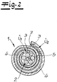
- a casing 1 for elongate material 2 is shown.
- the elongate product 2 is a plurality of combined cable strands, cable sets, etc. in a motor vehicle.
- the casing 1 With the help of the casing 1 is now the elongated material 2 or the individual cable strands are wrapped in their longitudinal extent.
- the sheath 1 thus corresponds to a longitudinal coil as a sheath, as the Fig. 2 shows and its preparation in detail in the Fig. 1A to 1C is shown.
- an adhesive tape 3, 4 equipped with an adhesive coating 3 is first provided.
- the adhesive coating 3 covers a carrier 4 of the adhesive tape 3, 4 on its front side substantially over the entire surface, like the Fig. 1A makes it clear.
- the adhesive tape 3, 4 is equipped overall with a width B.
- the carrier 4 of the adhesive tape 3, 4 may be one of a woven or knitted fabric.
- a PET (polyethylene terephthalate) fabric or a polyamide fabric is used.
- the carrier 4 can also be designed as a suede carrier or knitted fabric and scrim.
- the carrier 4 is a textile carrier 4, which in principle may also be formed as a nonwoven.
- the carrier 4 of the adhesive tape 3, 4 can also take on additional functions, in addition to its basic function, to provide an application surface for the adhesive coating 3.
- the carrier 4 on its surface facing the adhesive coating 3 with a paint coating, a film coating, etc. equipped is to protect after application of the sheathing so encased cable strands respectively the elongate Good 2 from moisture, such as splashing.
- the support 4 may in principle also be formed as a film.
- the invention is based on the fundamental finding that when the jacket 1 is attached to the elongate material 2, the surface of the adhesive tape 3, 4 facing the adhesive coating 3 faces outward, and thus can assume the described additional function particularly advantageously.
- the carrier 4 can act as a heat or heat shield when the casing 1 is to be mounted in the range of hot engine parts, in particular for wrapping cables in the engine compartment of a motor vehicle.
- the carrier 4 may be designed as a metal foil.
- the adhesive tape 3,4 has a width B in the range of about 80 mm to 600 mm.
- the width B is in the range between 80 mm and 300 mm.
- the basis weight of the respective adhesive tape 3, 4 is in the range of 40 g / m 2 to 800 g / m 2 and preferably between 100 g / m 2 and 500 g / m 2 settled. Its thickness may be in the range between 0.1 mm to 5 mm and preferably in the range between 0.2 mm to 1 mm.
- Adhesive coating 3 is an adhesive based on natural or synthetic rubber. Usually an acrylate adhesive and in particular hotmelt adhesive is used. In principle, it is also possible to use adhesives based on silicone, polyurethane or polyether.
- the invention recommends values in the range between about 20 g / m 2 to 300 g / m 2 .
- the adhesive tape 3,4 equipped on one side with the adhesive coating 3 is combined to form a laminate 3, 4, 5 by means of a carrier tape 5.
- the one (single) adhesive tape 3, 4 is applied to the carrier tape 5 in longitudinal extension, defining a first projection Ü 1 on at least one of its two longitudinal edges, as in the transition from the Fig. 1B to Fig. 1C becomes clear.
- the adhesive-coated carrier tape 5 is glued to the adhesive coating 3 of the associated adhesive tape 3, 4. This is done in such a way that the single adhesive tape 3, 4 coated on one side is arranged on the front side 5 a of the carrier tape 5 in the example case or glued to the front side 5 a. In the Fig. 1B is then still the back 5b of the carrier tape 5 can be seen. In any case, the carrier tape 5 with its front side 5a is pressed directly onto the adhesive coating 3 of the adhesive tape 3, 4 and then adheres to the adhesive coating 3.
- the carrier 4 of the adhesive tape 3, 4 at its rear side, ie, the side facing away from the carrier tape 5 or the adhesive coating 3, equipped with a further second adhesive coating 7.
- the carrier tape 5 is located on the front side of the adhesive tape 3, 4 and is arranged there, the second adhesive coating 7 is placed on the rear side of the adhesive tape 3, 4.
- the adhesive used at this point can be applied by spraying taking into account a mask on the back of the support 4.
- the further second adhesive coating 7 is shown clearly thicker than the first adhesive coating 3. This different form of presentation serves only to make clear the manufacturing process and the arrangement of the further second adhesive coating 7.
- both adhesive coatings 3, 7 are generally applied to the associated carrier 4 with comparable surface application weights or areal masses. This surface application weight or the basis weight is usually in the range of 30 g / m 2 to 300 g / m 2 settled.
- the adhesive coating 7 is present on a transfer film, not shown, and is applied with the aid of the transfer film to the back of the carrier 4.
- Other procedures for applying the adhesive coating 7 on the back of the carrier 4 are encompassed by the invention, for example, the so-called “kiss coating” or the “curtain coating”.
- the adhesive coating 7 can be defined on the rear side of the carrier 4 with the aid of the previously discussed spray coating method.
- the overall design is such that the adhesive tape 3, 4 with its first adhesive coating 3, each defining a supernatant Ü 1 ; Ü 2 at its two longitudinal edges of the carrier tape. 5 is created.
- the orientation takes place in such a way that the adhesive tape 3, 4 is aligned with the two protrusions Ü 1 and Ü 2 with the adhesive coating 3 facing outwards in each case.
- the first supernatant Ü 1 is the fixation strip already mentioned in the introduction.
- the second supernatant Ü 2 acts as a closure strip, as will be explained in more detail below.
- the second adhesive coating 7 is arranged offset at the back of the support 4 with respect to a central plane Z in the direction of the first projection Ü 1 .
- This offset takes account of the fact that when attaching the shroud as shown by Fig. 2 the laminate 3, 4, 5 envelops the elongated product 2, taking into account a more than simple rotation, so that no uncovered regions of the elongated product 2 be observed and the cable enclosed at this point optimally protected against mechanical influences.
- the second adhesive coating 7 has a width D which corresponds to the width of the second protrusion Ü 2 or of the closure strip or exceeds the width of the protrusion Ü 2 in question.
- the respective supernatant Ü 1 , Ü 2 has a width, which is designed to be significantly smaller in comparison to the width B of the adhesive tape. In fact, at this point, widths of the supernatant Ü 1 , Ü 2 are observed, which are in the range of 5% to 30% of the width of the adhesive tape. That means: Ü 1 , Ü 2 ⁇ 0.05 to 0.3 B.
- the adhesive tape 3, 4 is oriented at its two projections Ü 1 , Ü 2 with the adhesive coating 3 pointing outwards in each case enables the laminate 3, 4, 5 to be wound particularly easily around the elongated material 2.
- the laminate 3, 4, 5 is first fixed with the adhesive coating 3 on the associated first projection Ü 1 or the fixing strip on the elongated material 2.
- the sheath encases the elongated product 2 taking into account almost twice the longitudinal wrapping. Of course this is not mandatory. That is, within the scope of the invention are not only multiple sheaths, as shown, but the elongated material 2 can also be equipped with, for example, only a simple envelope. However, this is not shown in detail.
Landscapes
- Engineering & Computer Science (AREA)
- Textile Engineering (AREA)
- Architecture (AREA)
- Civil Engineering (AREA)
- Structural Engineering (AREA)
- Chemical & Material Sciences (AREA)
- Organic Chemistry (AREA)
- Manufacturing & Machinery (AREA)
- Adhesive Tapes (AREA)
- Manufacturing Of Electric Cables (AREA)
- Laminated Bodies (AREA)
Description
Die Erfindung betrifft ein Verfahren zur Herstellung einer Ummantelung für langgestrecktes Gut, insbesondere einer Umhüllung für Kabelsätze, wonach ein Klebeband aus einem Träger und einer den Träger an seiner Frontseite vollflächig bedeckenden ersten Klebebeschichtung mit einem klebebeschichtungsfreien Trägerband zu einem Laminat vereinigt wird, indem das Klebeband mit seiner ersten Klebebeschichtung unter Definition eines ersten Überstandes an wenigstens einer seiner beiden Längskanten an das Trägerband angelegt wird, und wonach der Träger des Klebebandes zusätzlich an seiner Rückseite teilflächig mit einer weiteren zweiten Klebebeschichtung ausgerüstet wird.The invention relates to a method for producing a casing for elongated material, in particular a casing for cable sets, according to which an adhesive tape of a carrier and the carrier on its front side over the entire surface covering the first adhesive coating is combined with a adhesive-free carrier tape to form a laminate by the adhesive tape its first adhesive coating, defining a first supernatant, is applied to the carrier tape at at least one of its two longitudinal edges, and then the carrier of the adhesive tape is additionally provided on its rear side with a further second adhesive coating.
Die erste Klebebeschichtung bedeckt den Träger an seiner Frontseite im Wesentlichen vollflächig. D.h., die Erfindung umfasst nicht nur flächenmäßig durchgängige Klebebeschichtungen der gesamten Frontseite des Trägers, sondern prinzipiell auch eine die Frontseite bedeckende Streifenbeschichtung oder sogar auch eine nur punktuelle Beschichtung der Frontseite mit dem betreffenden Kleber.The first adhesive coating covers the carrier on its front side substantially over the entire surface. That is, the invention comprises not only surface-consistent adhesive coatings of the entire front of the wearer, but in principle also a front coating covering strip coating or even a single-point coating of the front side with the adhesive in question.
Das Trägerband ist demgegenüber klebebeschichtungsfrei ausgelegt. D.h., bei dem Trägerband handelt es sich ausdrücklich nicht um ein Klebeband, weil eine Klebebeschichtung fehlt. Gleichwohl kann das Trägerband prinzipiell mit einer nicht klebenden Beschichtung ausgerüstet werden, beispielsweise einer Lackbeschichtung oder ähnlichem.In contrast, the carrier tape is designed to be adhesive-free. That is, the carrier tape is expressly not an adhesive tape because an adhesive coating is missing. However, the carrier tape can in principle be equipped with a non-adhesive coating, such as a paint coating or the like.
Das Klebeband wird zur Vereinigung mit dem Trägerband mit seiner ersten Klebebeschichtung an das Trägerband angelegt. Hierbei wird ein erster Überstand des Klebebandes gegenüber dem Trägerband definiert. An diesem ersten Überstand ist folglich die nach außen weisende Klebebeschichtung des Klebebandes realisiert, welche im Regelfall als Fixierstreifen des Laminates zur Festlegung an dem langgestreckten Gut fungiert, wie nachfolgend im Detail noch erläutert wird. Diese Vorgehensweise ist aus der
Im Stand der Technik nach der
Zum einschlägigen Stand der Technik gehört auch die Lehre nach der
Dadurch wird zwar die Möglichkeit geschaffen, Kabelsätze zu bandagieren und einen signifikanten Schutz gegen mechanische Beschädigungen durch Scheuern und Reiben an scharfen Kanten, Graten und Schweißpunkten zu erreichen. Allerdings ist die Herstellung aufwendig. Denn die insgesamt drei einseitig klebend ausgerüsteten Klebebänder müssen in bestimmter Verfahrensabfolge mit Versatz aufeinander laminiert werden. Etwaige Korrekturen sind bei dieser Vorgehensweise nicht möglich, so dass gegebenenfalls mit Schutzfilmen gearbeitet werden muss.This creates the opportunity to bandage cable harnesses and provide significant protection against mechanical damage Scouring and rubbing to achieve sharp edges, burrs and welds. However, the production is complicated. Because the three adhesive tapes equipped on one side must be laminated with offset in a certain sequence of processes. Any corrections are not possible with this procedure, so that it may be necessary to work with protective films.
Bei der
Beim gattungsbildenden Stand der Technik nach der
Der Erfindung liegt das technische Problem zugrunde, ein derartiges Verfahren zur Herstellung einer Ummantelung für langgestrecktes Gut so weiter zu entwickeln, dass die Produktion vereinfacht ist und insgesamt verringerte Kosten beobachtet werden.The invention is based on the technical problem of such a method for producing a casing for elongated Good so on develop that production is simplified and overall reduced costs are observed.
Zur Lösung dieser technischen Problemstellung ist ein Verfahren nach Anspruch 1 vorgesehen.To solve this technical problem, a method according to claim 1 is provided.
Dabei wird die teilflächige weitere zweite Klebebeschichtung an der Rückseite des Trägers des Klebebandes erst aufgebracht, wenn das Klebeband mit dem Träger vereinigt worden ist. Grundsätzlich ist es aber auch möglich, sowohl die erste als auch die zweite Klebebeschichtung von vornherein auf dem Träger vorzusehen und das solchermaßen ausgerüstete Klebeband insgesamt mit dem Träger zu dem Laminat zu vereinigen.In this case, the part-surface further second adhesive coating is applied to the rear side of the carrier of the adhesive tape only when the adhesive tape has been combined with the carrier. In principle, however, it is also possible to provide both the first and the second adhesive coating on the carrier from the outset and to combine the thus-equipped adhesive tape as a whole with the carrier to form the laminate.
Im Regelfall kommt jedoch ein selbstklebendes Klebeband an dieser Stelle zum Einsatz, welches bereits über die erste Klebebeschichtung an der Frontseite verfügt, dessen Rückseite allerdings - zunächst - klebebeschichtungsfrei ausgebildet ist. Sobald dieses selbstklebend ausgerüstete Klebeband mit dem Träger zu dem Laminat vereinigt worden ist, kann in einem abschließenden Schritt die Rückseite des Trägers des betreffenden Klebebandes zusätzlich mit der weiteren zweiten Klebebeschichtung ausgerüstet werden.As a rule, however, a self-adhesive tape is used at this point, which already has the first adhesive coating on the front side, the back side of which, however, is initially designed to be adhesive-free. Once this self-adhesive tape has been combined with the carrier to the laminate, in a final step, the back of the carrier of the tape in question can be additionally equipped with the other second adhesive coating.
Wie bereits erläutert, ist der Träger des Klebebandes an seiner Frontseite mit der ersten Klebebeschichtung ausgerüstet, welche die fragliche Frontseite im Wesentlichen vollflächig bedeckt. Dagegen sorgt die an der Rückseite des Trägers vorgesehene zweite Klebebeschichtung nur für eine im Wesentlichen teilflächige Klebebeschichtung. Hiermit ist gemeint, dass die fragliche Rückseite des Trägers lediglich zum Teil von der zweiten Klebebeschichtung bedeckt wird, nämlich über eine Teilfläche gesehen. Die Relativierung im Wesentlichen drückt in gleicher Weise wie bei der ersten Klebebeschichtung aus, dass die zweite Klebebeschichtung prinzipiell auch als Streifenbeschichtung, punktförmige Beschichtung etc. ausgebildet sein kann, solange die Klebebeschichtung die fragliche Rückseite lediglich teilflächig erfasst.As already explained, the carrier of the adhesive tape is equipped on its front side with the first adhesive coating, which covers the front side in question substantially over its entire area. In contrast, the second adhesive coating provided on the rear side of the carrier only provides for an essentially partial adhesive coating. By this is meant that the rear side of the carrier in question is only partially covered by the second adhesive coating, namely seen over a partial surface. The relativization essentially expresses in the same way as in the first adhesive coating that the Second adhesive coating may in principle be designed as a strip coating, punctiform coating, etc., as long as the adhesive coating detects the back in question only part of the area.
So oder so verzichtet die Erfindung zunächst einmal auf die Handhabung und Verarbeitung von drei jeweils einseitig klebend ausgerüsteten Klebebändern, die nach Lehre der
Bei dem klebebeschichtungsfreien Trägerband handelt es sich typischerweise um ein textiles Bandmaterial. Grundsätzlich kann an dieser Stelle auch mit einer Kunststofffolie, einer Metallfolie, einer Papierfolie, einer Papierbahn oder einem anderen flächigen Material gearbeitet werden. Sofern das Trägermaterial bzw. das Material für das Trägerband als textiles Bandmaterial ausgebildet ist, haben sich flächige Vliesmaterialen, Gewebe, Gewirke, Velours, aber auch Filz- oder Schaumstofflagen als günstig erwiesen. Da darüber hinaus die erfindungsgemäße Umhüllung zur Herstellung einer Ummantelung des langgestreckten Gutes eingesetzt wird, lassen sich bestimmte zusätzliche Eigenschaften bei dem Trägerband je nach Materialwahl realisieren.The adhesive-coating-free carrier tape is typically a textile tape material. In principle, it is also possible here to work with a plastic film, a metal foil, a paper foil, a paper web or another flat material. If the carrier material or the material for the carrier tape is formed as a textile strip material, flat nonwoven materials, woven fabric, knitted fabric, velor, but also felt or foam layers have proven to be favorable. In addition, since the enclosure according to the invention is used to produce a jacket of the elongated material, certain additional properties can be realized in the carrier tape depending on the choice of material.
Hierbei geht die Erfindung insgesamt von der Erkenntnis aus, dass das genannte Trägerband bei der Herstellung der Ummantelung in unmittelbarem körperlichen Kontakt zu dem langgestreckten Gut kommt. Meistens wird ein Kontakt des Trägerbandes mit dem langgestreckten Gut über eine Länge beobachtet, welche wenigstens einem halben Wickel entspricht. Denn bei der Herstellung der Ummantelung wird so vorgegangen, dass die Umhüllung respektive das Laminat um das langgestreckte Gut längsgewickelt wird.In this case, the invention as a whole is based on the recognition that said carrier tape comes in direct physical contact with the elongate product during the production of the casing. Mostly a contact of the carrier tape is observed with the elongated Good over a length which corresponds to at least half a winding. Because in the production of the sheath, the procedure is such that the envelope or the laminate is longitudinally wound around the elongated material.
Durch den körperlichen Kontakt zwischen dem Trägerband und dem langgestreckten Gut bei der Herstellung der Ummantelung empfiehlt es sich beispielsweise, das Trägerband aus einem Velours oder auch einem Schaumstoff herzustellen, wenn Klappergeräusche des langgestreckten Gutes zu befürchten sind oder unterdrückt werden müssen. Auch andere Funktionen des Trägerbandes sind möglich, beispielsweise derart, dass Feuchtigkeit aufgenommen wird, so dass Vliesmaterialien besonders geeignet sind. Ebenso kann das Trägermaterial eine zusätzliche elektrische Isolierung zur Verfügung stellen, die man dadurch gewährleistet, dass an dieser Stelle beispielsweise Kunststoffe mit hohem elektrischen Widerstand bearbeitet werden. Jedenfalls ist diesen sämtlichen Materialien gemein, dass die Flächenmasse des Trägerbandes im Regelfall unterhalb von 500 g/m2 und insbesondere sogar weniger als 250 g/m2 beträgt.Due to the physical contact between the carrier tape and the elongated material in the production of the sheath, it is recommended, for example, to produce the carrier tape of a suede or a foam when rattling noises of the elongated material are to be feared or suppressed. Other functions of the carrier tape are possible, for example, such that moisture is absorbed, so that nonwoven materials are particularly suitable. Likewise, the carrier material can provide an additional electrical insulation, which is ensured by the fact that, for example, plastics are processed with high electrical resistance at this point. In any case, this common to all materials that the basis weight of the carrier tape is usually below 500 g / m 2 and in particular even less than 250 g / m 2 .
Wie bereits erläutert, ist das Trägerband erfindungsgemäß klebebeschichtungsfrei ausgebildet, verfügt also nicht über eine Klebebeschichtung. Grundsätzlich sind natürlich prinzipiell Beschichtungen wie eine Lackbeschichtung denkbar. Aus Kostengründen wird man hierauf im Allgemeinen verzichten und das Trägerband nicht nur klebebeschichtungsfrei, sondern im Regelfall sogar generell beschichtungsfrei auslegen.As already explained, the carrier tape according to the invention is formed adhesive-free, so does not have an adhesive coating. In principle, of course, coatings such as a paint coating are conceivable in principle. For reasons of cost, this will generally be dispensed with, and the carrier tape will not only be adhesive-free, but generally even coat-free as a rule.
Da das Trägerband klebebeschichtungsfrei ausgebildet ist, kann es problemlos und ohne Schwierigkeiten bei der Orientierung mit dem einseitig mit der Klebebeschichtung ausgerüsteten einen (einzigen) Klebeband zu dem Laminat vereinigt werden. Hierzu ist es lediglich erforderlich, dass das fragliche (einzige) Klebeband mit seiner ersten Klebebeschichtung an das Trägerband angelegt wird. Folgerichtig kommt das Trägerband in Kontakt mit der ersten Klebebeschichtung und wird bei diesem Vorgang im einfachsten Fall schlicht und ergreifend mit dem Klebeband verklebt.Since the carrier tape is formed adhesive-free, it can be easily and without difficulty in the orientation with the one-sided with the adhesive coating equipped one (single) adhesive tape combined to the laminate. For this it is only necessary that the (only) adhesive tape in question is applied to the carrier tape with its first adhesive coating. Consequently, the carrier tape comes in contact with the first adhesive coating and is glued in this process in the simplest case, simply and movingly with the tape.
Bei der zweiten Klebebeschichtung an der Rückseite des Trägers des Klebebandes handelt es sich um eine solche Klebebeschichtung, die im einfachsten Fall mit Hilfe einer Maske auf die fragliche Rückseite des Trägers aufgebracht wird. Dadurch lässt sich einfach und problemlos die angesprochene teilflächige Beschichtung mit der weiteren zweiten Klebebeschichtung realisieren. Alternativ hierzu kann die zweite Klebebeschichtung auch von einem Transferband respektive Transferfilm getragen werden und mit Hilfe dieses Transferbandes bzw. Transferfilmes dann an der Rückseite des Klebebandes angebracht werden.The second adhesive coating on the back of the carrier of the adhesive tape is such an adhesive coating, which is applied in the simplest case with the aid of a mask on the rear side of the carrier in question. As a result, the mentioned partial area coating with the further second adhesive coating can be realized simply and without problems. Alternatively, the second adhesive coating can also be carried by a transfer belt or transfer film and then attached to the back of the adhesive tape by means of this transfer belt or transfer film.
Dabei wird man meistens so vorgehen, dass das Klebeband mit seiner ersten Klebebeschichtung unter Definition jeweils eines Überstandes an seinen beiden Längskanten an das Trägerband angelegt wird. D.h., nach vorteilhafter Ausgestaltung ist nicht nur der erste Überstand realisiert, sondern zusätzlich ein weiterer zweiter Überstand, und zwar an den beiden Längskanten des Klebebandes. Dadurch steht das Klebeband mit seinen beiden Längskanten gegenüber dem Trägerband über und weist die Klebebeschichtung des Klebebandes im Bereich des jeweiligen Überstandes nach außen hin. Dadurch können die beiden Überstände zur Fixierung und Festlegung der Ummantelung an dem langgestreckten Gut besonders vorteilhaft eingesetzt werden.In this case, one will usually proceed in such a way that the adhesive tape is applied to the carrier tape with its first adhesive coating, each defining a supernatant at its two longitudinal edges. That is, according to an advantageous embodiment, not only the first supernatant is realized, but in addition a further second supernatant, namely at the two longitudinal edges of the adhesive tape. As a result, the adhesive tape projects with its two longitudinal edges opposite the carrier tape and has the adhesive coating of the adhesive tape in the region of the respective projection to the outside. As a result, the two supernatants for fixing and fixing the casing on the elongated material can be used particularly advantageously.
Tatsächlich fungiert der erste Überstand in diesem Zusammenhang meistens als Fixierstreifen und sorgt dafür, dass das Laminat an dem langgestreckten Gut festgelegt wird. Demgegenüber fungiert der zweite Überstand mit der dort ebenfalls freiliegenden und nach außen weisenden Klebebeschichtung meistens als Verschlussstreifen. Tatsächlich ist die Auslegung im Regelfall so getroffen, dass die nach außen weisende Klebebeschichtung des Verschlussstreifens mit der weiteren zweiten Klebebeschichtung am Ende des Ummantelungsvorganges in Kontakt kommt, so dass ein besonders haltbarer endseitiger Verschluss durch die beiden sich berührenden ersten und zweiten Klebebeschichtungen zur Verfügung gestellt wird.In fact, in this context, the first supernatant usually acts as a fixation strip, causing the laminate to become attached to the elongated product. In contrast, the second supernatant with the also there exposed and outwardly facing adhesive coating usually acts as a closure strip. In fact, the design is usually such that the outwardly facing adhesive coating of the closure strip comes into contact with the further second adhesive coating at the end of the coating process, so that a particularly durable end closure is provided by the two contacting first and second adhesive coatings ,
Die beiden vorteilhaft vorgesehenen Überstände verfügen in der Regel über eine unterschiedliche Breite. Tatsächlich beobachtet man an dieser Stelle ein Breitenverhältnis der beiden Überstände und folglich des Fixierstreifens bzw. ersten Überstandes im Vergleich zum Verschlussstreifen bzw. zum zweiten Überstand im Bereich von 1:1 bis 1:5 und vorzugsweise im Bereich von 1:1 bis 1:3.The two advantageously provided supernatants usually have a different width. In fact, at this point, a width ratio of the two supernatants and consequently of the fixing strip or first supernatant is observed in the range from 1: 1 to 1: 5 and preferably in the range from 1: 1 to 1: 3 compared to the closure strip or the second supernatant ,
Außerdem ist die Auslegung meistens so getroffen, dass das Klebeband als solches eine Breite aufweist, welche diejenige des Trägerbandes um den Betrag des bzw. der Überstände übersteigt. Sofern nur ein Überstand des Klebebandes gegenüber dem Trägerband realisiert ist, weist das Klebeband eine Breite auf, welche sich aus der Summe der Breite des Trägerbandes und der Breite des ersten Überstandes zusammensetzt. Sind jedoch zwei Überstände realisiert, so setzt sich die Breite des Klebebandes aus der Summe der beiden Breiten der Überstände zuzüglich der Breite des Trägerbandes zusammen.In addition, the design is usually made so that the adhesive tape as such has a width which exceeds that of the carrier tape by the amount of the or the supernatants. If only one supernatant of the adhesive tape is realized with respect to the carrier tape, the adhesive tape has a width, which is composed of the sum of the width of the carrier tape and the width of the first supernatant. However, if two projections are realized, then the width of the adhesive tape is composed of the sum of the two widths of the projections plus the width of the carrier tape.
Da das Klebeband an seinen beiden Überständen mit der jeweils nach außen weisenden Klebebeschichtung angeordnet wird und diese Klebebeschichtungen für die Verklebung zur Verfügung stehen, können auf einfache Art und Weise einerseits der Fixierstreifen und andererseits der Verschlussstreifen wie erläutert definiert und umgesetzt werden.Since the adhesive tape is arranged on its two projections with the respective outwardly facing adhesive coating and these adhesive coatings are available for bonding, can be defined and implemented in a simple manner on the one hand, the fixing strip and on the other hand, the closure strip as explained.
Die zweite Klebebeschichtung an der Rückseite des Trägers ist im Allgemeinen nicht zentral im Vergleich zum Klebeband angeordnet. Vielmehr wird die zweite Klebebeschichtung an der Rückseite des Trägers gegenüber einer Zentralebene in Richtung auf den ersten Überstand versetzt angeordnet. Bei dieser Zentralebene des Klebebandes handelt es sich um die Spiegelsymmetrieebene für das Klebeband, welche das einseitig mit der Klebebeschichtung ausgerüstete Klebeband in seiner Längserstreckung in zwei gleiche Teilbänder unterteilt. Gegenüber dieser Zentralebene ist die zweite Klebebeschichtung an der Rückseite des Trägers in Richtung auf den ersten Überstand versetzt angeordnet.The second adhesive coating on the back of the carrier is generally not centrally located relative to the adhesive tape. Rather, the second adhesive coating is arranged offset on the rear side of the carrier relative to a central plane in the direction of the first projection. This central plane of the adhesive tape is the mirror symmetry plane for the adhesive tape, which subdivides the adhesive tape, which is equipped on one side with the adhesive coating, into two equal subbands in its longitudinal extension. Opposite this central plane, the second adhesive coating is arranged offset on the rear side of the carrier in the direction of the first projection.
Diese Anordnung trägt dem Umstand Rechnung, dass der erste Überstand als Fixierstreifen fungiert und dann die Ummantelung um das langgestreckte Gut längsgewickelt wird. Bei diesem Vorgang kommt es zu einer zumindest im End- oder Verschlussbereich des Längswickels beobachteten mehrschichtigen Anordnung des Laminates, so dass sich der Versatz erklärt.This arrangement takes into account the fact that the first supernatant acts as a fixing strip and then the sheathing is wound longitudinally around the elongated product. In this process, there is a observed at least in the end or closure region of the longitudinal coil multilayer arrangement of the laminate, so that explains the offset.
Die zweite Klebebeschichtung verfügt über eine Breite, welche in etwa derjenigen des zweiten Überstandes entspricht. Aufgrund der zuvor bereits geschilderten Größenverhältnisse bzw. Breitenverhältnisse des ersten im Vergleich zum zweiten Überstandes im Bereich von 1:1 bis 1:5 ist die zweite Klebebeschichtung mit einer Breite ausgerüstet, welche derjenigen des zweiten Überstandes entspricht und regelmäßig die Breite des ersten Überstandes überschreitet. Insbesondere sollte die Breite des zweiten Überstandes bzw. des Verschlussstreifens mindestens der Breite der zweiten Klebebeschichtung entsprechen, um den gewünschten sicheren Verschluss der Ummantelung durch den beschriebenen gegenseitigen Kontakt herzustellen.The second adhesive coating has a width which corresponds approximately to that of the second supernatant. Due to the previously described size ratios or width ratios of the first compared to the second supernatant in the range of 1: 1 to 1: 5, the second adhesive coating is equipped with a width which corresponds to that of the second supernatant and regularly the width of the first supernatant exceeds. In particular, the width of the second projection or closure strip should be at least equal to the width of the second adhesive coating to produce the desired secure closure of the jacket by the described mutual contact.
Der Überstand selbst weist eine Breite auf, welche deutlich unterhalb der Breite des Klebebandes angesiedelt ist. Tatsächlich empfiehlt die Erfindung in diesem Zusammenhang eine Auslegung, wonach der Überstand mit einer Breite ausgerüstet ist, welche im Vergleich zur Breite des Klebebandes 5% bis 30% beträgt. Vorzugsweise liegt die Breite des Überstandes im Vergleich zur Breite des Klebebandes im Bereich von 10% bis 20% der Breite des Klebebandes. Dadurch ist sichergestellt, dass das Klebeband mit seinem einen oder den beiden Überständen maximal zu 30% seiner Breite an der jeweiligen Längskante übersteht.The supernatant itself has a width which is significantly below the width of the adhesive tape. In fact, the invention in this context recommends a design according to which the supernatant is equipped with a width which is 5% to 30% compared to the width of the adhesive tape. Preferably, the width of the supernatant is in the range of 10% to 20% of the width of the adhesive tape compared to the width of the adhesive tape. This ensures that the adhesive tape with its one or both projections protrudes a maximum of 30% of its width at the respective longitudinal edge.
Bei der Ummantelung des langgestreckten Gutes wird erfindungsgemäß so vorgegangen, dass das Laminat mit seinem ersten Überstand parallel zum langgestreckten Gut ausgerichtet und hieran festgelegt wird. Der erste Überstand fungiert also als Fixierstreifen. Anschließend wird das Laminat um das Gut längsgewickelt und abschließend mit der zweiten Klebebeschichtung zum Längswickel verklebt. In diesem Zusammenhang fungiert in der Regel der zweite Überstand als Verschlussstreifen und kommt mit der zweiten Klebebeschichtung wie beschrieben in Kontakt, so dass ein besonders fester und langhaltender Verschluss endseitig der Längsumhüllung bzw. des Längswickels beobachtet wird. Auf diese Weise kann insgesamt auch eine Ummantelung für langgestrecktes Gut hergestellt werden.In the casing of the elongated material, the procedure according to the invention is such that the laminate is aligned with its first projection parallel to the elongated material and fixed thereto. The first supernatant thus acts as a fixing strip. Subsequently, the laminate is wound longitudinally around the product and finally glued to the second adhesive coating for longitudinal winding. In this context, the second supernatant usually acts as a closure strip and comes into contact with the second adhesive coating as described, so that a particularly strong and long-lasting closure is observed at the end of the longitudinal wrap or the longitudinal wrap. In this way, a jacket for elongated material can be produced in total.
Gegenstand der Erfindung ist auch eine Umhüllung, die zur Herstellung einer Ummantelung für langgestrecktes Gut besonders geeignet ist. Die fragliche Umhüllung wird im Anspruch 10 beschrieben.The invention also provides a casing which is particularly suitable for producing a casing for elongate material. The enclosure in question is described in claim 10.
Im Ergebnis werden ein Verfahren zur Herstellung einer Ummantelung für langgestrecktes Gut und eine korrespondierende Umhüllung beschrieben, die beide für einen besonderen mechanischen Schutz des langgestreckten Gutes sorgen. Hierbei handelt es sich meistens um einen oder mehrere Kabelstränge. Außerdem wird die Ummantelung bzw. Umhüllung im Regelfall in Verbindung mit Kabelsträngen in Automobilen eingesetzt. Dabei sorgt die Ummantelung insgesamt für einen Schutz der einzelnen Kabelstränge bzw. Kabelsätze gegen mechanische Schäden. Diese können beispielsweise durch Scheuern und Schneiden in einem Kraftfahrzeug auftreten und werden erfindungsgemäß beherrscht.As a result, a method for producing an elongated product casing and a corresponding casing are described, both of which provide for a special mechanical protection of the elongated product. These are usually one or more cable strands. In addition, the sheath or sheath is usually used in conjunction with cable harnesses in automobiles. Overall, the sheathing ensures protection of the individual cable strands or cable sets against mechanical damage. These can occur, for example, by scrubbing and cutting in a motor vehicle and are controlled according to the invention.
Die beschriebene Vorgehensweise sowie die zugehörige Umhüllung lassen sich besonders einfach und kostengünstig realisieren. Das ist vor dem Hintergrund des enormen Preiswettbewerbes auf dem Automobilsektor von besonderer Bedeutung. Hierin sind die wesentlichen Vorteile zu sehen.The procedure described and the associated envelope can be realized in a particularly simple and cost-effective manner. This is of particular importance in view of the enormous price competition in the automotive sector. Here are the main benefits.
Im Folgenden wird die Erfindung anhand lediglich ein Ausführungsbeispiel darstellenden Zeichnung näher erläutert; es zeigen:
- Fig. 1A bis 1C
- ein Verfahren zur Herstellung einer Ummantelung für langgestrecktes Gut in verschiedenen Verfahrensstufen und
- Fig. 2
- die am langgestreckten Gut angebrachte Ummantelung.
- Fig. 1A to 1C
- a method for producing a casing for elongate material in various process stages and
- Fig. 2
- the casing attached to the elongated product.
In den Figuren ist eine Ummantelung 1 für langgestrecktes Gut 2 dargestellt. Bei dem langgestreckten Gut 2 handelt es sich im Ausführungsbeispiel und nicht einschränkend um mehrere zusammengefasste Kabelstränge, Kabelsätze etc. in einem Kraftfahrzeug. Mit Hilfe der Ummantelung 1 wird nun das langgestreckte Gut 2 bzw. werden die einzelnen Kabelstränge in ihrer Längserstreckung umhüllt. Die Ummantelung 1 korrespondiert folglich zu einem Längswickel als Umhüllung, wie dies die
Bei der Herstellung der Ummantelung 1 wird zunächst ein mit einer Klebebeschichtung 3 ausgerüstetes Klebeband 3, 4 zur Verfügung gestellt. Die Klebebeschichtung 3 bedeckt einen Träger 4 des Klebebandes 3, 4 an seiner Frontseite im Wesentlichen vollflächig, wie die
Bei dem Träger 4 des Klebebandes 3, 4 kann es sich um einen solchen aus einem Gewebe oder Gewirke handeln. Im Regelfall kommt ein PET (Polyethylenterephthalat)-Gewebe oder auch ein Polyamid-Gewebe zum Einsatz. Generell kann der Träger 4 aber auch als Velourträger oder Gewirke sowie Gelege ausgebildet sein. Im Allgemeinen handelt es sich bei dem Träger 4 um einen textilen Träger 4, der grundsätzlich auch als Vlies ausgebildet sein mag.The
Der Träger 4 des Klebebandes 3, 4 kann auch noch weitere Funktionen übernehmen, zusätzlich zu seiner grundsätzlichen Funktion, eine Auftragsfläche für die Klebebeschichtung 3 zur Verfügung zu stellen. So ist es denkbar, dass der Träger 4 auf seiner der Klebebeschichtung 3 gegenüberliegenden Oberfläche mit einer Lackbeschichtung, einer Folienbeschichtung etc. ausgerüstet ist, um nach Anbringung der Ummantelung die solchermaßen umhüllten Kabelstränge respektive das langgestreckte Gut 2 vor Feuchtigkeit, beispielsweise Spritzwasser zu schützen. In diesem Zusammenhang kann der Träger 4 grundsätzlich auch als Folie ausgebildet sein. Hierbei geht die Erfindung von der grundsätzlichen Erkenntnis aus, dass bei angebrachter Ummantelung 1 an dem langgestreckten Gut 2 die der Klebebeschichtung 3 gegenüberliegende Oberfläche des Klebebandes 3, 4 nach außen hin weist, folglich die beschriebene Zusatzfunktion besonders vorteilhaft übernehmen kann.The
Darüber hinaus kann der Träger 4 als Hitze- oder Wärmeschild fungieren, wenn die Ummantelung 1 im Bereich heißer Motorteile angebracht werden soll, insbesondere zur Umhüllung von Kabeln im Motorraum eines Kraftfahrzeuges. In diesem Fall mag der Träger 4 als Metallfolie ausgelegt sein. Es ist aber auch denkbar, einen textilen Träger mit einer Metallfolie auf seiner der Klebebeschichtung 3 entgegengesetzten Oberfläche auszurüsten, um insbesondere Wärmestrahlung zu reflektieren. Dann wirkt die nach außen weisende Metallfolie als gleichsam Wärmeschild.In addition, the
Das Klebeband 3,4 verfügt über eine Breite B im Bereich von ca. 80 mm bis 600 mm. Vorzugsweise liegt die Breite B im Bereich zwischen 80 mm und 300 mm. Das Flächengewicht des jeweiligen Klebebandes 3, 4 ist im Bereich von 40 g/m2 bis 800 g/m2 und vorzugsweise zwischen 100 g/m2 und 500 g/m2 angesiedelt. Seine Dicke mag im Bereich zwischen 0,1 mm bis 5 mm und vorzugsweise im Bereich zwischen 0,2 mm bis 1 mm angesiedelt sein.The
Bei der Klebebeschichtung 3 handelt es sich um eine Klebemasse auf Basis von Natur- oder Synthesekautschuk. Meistens wird ein Acrylatkleber und insbesondere Hotmelt-Kleber eingesetzt. Grundsätzlich können auch Klebemassen auf Silikon-, Polyurethan- oder Polyetherbasis zum Einsatz kommen.
Als Auftragsgewichte für die Klebebeschichtung 3 empfiehlt die Erfindung Werte im Bereich zwischen ca. 20 g/m2 bis 300 g/m2.As coating weights for the
Das einseitig mit der Klebebeschichtung 3 ausgerüstete Klebeband 3,4 wird mit Hilfe eines Trägerbandes 5 zu einem Laminat 3, 4, 5 vereinigt. Zu diesem Zweck wird das eine (einzige) Klebeband 3, 4 in Längserstreckung unter Definition eines ersten Überstandes Ü1 an wenigstens einer seiner beiden Längskanten an das Trägerband 5 angelegt, wie dies beim Übergang von der
Bei diesem Vorgang wird das klebebeschichtungsfrei ausgebildete Trägerband 5 mit der Klebebeschichtung 3 des zugehörigen Klebebandes 3, 4 verklebt. Das geschieht derart, dass das einseitig beschichtete einzige Klebeband 3, 4 im Beispielfall an der Vorderseite 5a des Trägerbandes 5 angeordnet bzw. mit der Vorderseite 5a verklebt wird. In der
Nachdem das Trägerband 5 mit dem Klebeband 3, 4 zu dem Laminat 3, 4, 5 vereinigt worden ist, wird erfindungsgemäß der Träger 4 des Klebebandes 3, 4 an seiner Rückseite, d.h., der dem Trägerband 5 bzw. der Klebebeschichtung 3 abgewandten Seite, mit einer weiteren zweiten Klebebeschichtung 7 ausgerüstet. Während sich also das Trägerband 5 an der Vorderseite des Klebebandes 3, 4 befindet und dort angeordnet ist, ist die zweite Klebebeschichtung 7 an der Rückseite des Klebebandes 3, 4 platziert.After the
Man erkennt, dass die weitere zweite Klebebeschichtung 7 - ergänzend zu der ersten Klebebeschichtung 3 des Klebebandes 3, 4 - lediglich teilflächig an der Rückseite des betreffenden Klebebandes 3, 4 vorgesehen ist.It can be seen that the further second adhesive coating 7 is provided, in addition to the first
Um diese teilflächige Ausrüstung der Rückseite des Trägers 4 des Klebebandes 3, 4 im Detail zu realisieren, kann der an dieser Stelle eingesetzte Kleber durch Aufsprühen unter Berücksichtigung einer Maske auf die Rückseite des Trägers 4 aufgebracht werden. Im Ausführungsbeispiel ist die weitere zweite Klebebeschichtung 7 deutlich dicker als die erste Klebebeschichtung 3 dargestellt. Diese abweichende Darstellungsform dient lediglich dazu, um den Herstellungsprozess und die Anordnung der weiteren zweiten Klebebeschichtung 7 deutlich zu machen. Tatsächlich werden beide Klebebeschichtungen 3, 7 im Regelfall mit vergleichbaren Flächenauftragsgewichten bzw. Flächenmassen auf den zugehörigen Träger 4 aufgebracht. Dieses Flächenauftragsgewicht bzw. die Flächenmasse ist meistens im Bereich von 30 g/m2 bis 300 g/m2 angesiedelt.In order to realize this part-surface equipment of the back of the
Alternativ hierzu ist es auch möglich, dass die Klebebeschichtung 7 auf einem nicht dargestellten Transferfilm vorhanden ist und mit Hilfe des Transferfilmes auf die Rückseite des Trägers 4 aufgebracht wird. Auch andere Vorgehensweisen zur Anbringung der Klebebeschichtung 7 an der Rückseite des Trägers 4 werden von der Erfindung umfasst, beispielsweise das sogenannte "kiss coating" oder auch das "curtain coating". Darüber hinaus lässt sich die Klebebeschichtung 7 mit Hilfe des zuvor bereits angesprochenen Spühcoating-Verfahrens an der Rückseite des Trägers 4 definieren.Alternatively, it is also possible that the adhesive coating 7 is present on a transfer film, not shown, and is applied with the aid of the transfer film to the back of the
In topologischer Hinsicht ist die Auslegung insgesamt so getroffen, dass das Klebeband 3, 4 mit seiner ersten Klebebeschichtung 3 unter Definition jeweils eines Überstandes Ü1; Ü2 an seinen beiden Längskanten an das Trägerband 5 angelegt wird. Dabei erfolgt die Orientierung derart, dass das Klebeband 3, 4 an den beiden Überständen Ü1 und Ü2 mit der jeweils nach außen weisenden Klebebeschichtung 3 ausgerichtet wird. Bei dem ersten Überstand Ü1 handelt es sich um den einleitend bereits angesprochenen Fixierstreifen. Dagegen fungiert der zweite Überstand Ü2 als Verschlussstreifen, wie nachfolgend noch näher erläutert wird.In topological terms, the overall design is such that the
Man erkennt insbesondere anhand der
Außerdem ist das Klebeband 3, 4 insgesamt mit der bereits angesprochenen Breite B ausgerüstet, welche eine Breite C des Trägerbandes 5 um den Betrag der beiden Überstände Ü1, Ü2 übersteigt. D.h., im Rahmen des Ausführungsbeispiels gilt: ![]()
![]()
Anhand der
Die zweite Klebebeschichtung 7 verfügt über eine Breite D, welche der Breite des zweiten Überstandes Ü2 bzw. des Verschlussstreifens entspricht respektive die Breite des fraglichen Überstandes Ü2 überschreitet. Der jeweilige Überstand Ü1, Ü2 verfügt seinerseits über eine Breite, welche im Vergleich zur Breite B des Klebebandes deutlich kleiner ausgelegt ist. Tatsächlich werden an dieser Stelle Breiten des Überstandes Ü1, Ü2 beobachtet, die im Bereich von 5 % bis 30 % der Breite des Klebebandes liegen. D.h., es gilt:
Ü1, Ü2≈ 0,05 bis 0,3 B.The second adhesive coating 7 has a width D which corresponds to the width of the second protrusion Ü 2 or of the closure strip or exceeds the width of the protrusion Ü 2 in question. The respective supernatant Ü 1 , Ü 2 , in turn, has a width, which is designed to be significantly smaller in comparison to the width B of the adhesive tape. In fact, at this point, widths of the supernatant Ü 1 , Ü 2 are observed, which are in the range of 5% to 30% of the width of the adhesive tape. That means:
Ü 1 , Ü 2 ≈ 0.05 to 0.3 B.
Dadurch, dass das Klebeband 3, 4 an seinen beiden Überständen Ü1, Ü2 mit der jeweils nach außen weisenden Klebebeschichtung 3 orientiert wird, lässt sich das Laminat 3, 4, 5 besonders einfach um das langgestreckte Gut 2 längswickeln. Zu diesem Zweck wird das Laminat 3, 4, 5 zunächst mit der Klebebeschichtung 3 am zugehörigen ersten Überstand Ü1 bzw. dem Fixierstreifen an dem langgestreckten Gut 2 festgelegt.The fact that the
Anschließend wird die Umhüllung gemäß der Darstellung in der
In der
Es ist offensichtlich, dass je nach Variation der Breiten B, C, D und derjenigen der Überstände Ü1 sowie Ü2 unterschiedliche Gesamtbreiten des Laminates 3, 4, 5 und auch verschiedene Positionen sowie Größen des Fixierstreifens und Verschlussstreifens umgesetzt werden können. Dabei lassen sich insgesamt Gesamtbreiten des Laminates 3, 4, 5 im Bereich von ca. 80 mm bis 600 mm realisieren, so dass langgestreckte Güter 2 ganz unterschiedlichen Durchmessers ummantelt werden können. Hierbei handelt es sich selbstverständlich nur um beispielhafte und nicht einschränkende Abschätzungen.It is obvious that, depending on the variation of the widths B, C, D and those of the projections Ü 1 and Ü 2, different overall widths of the
Claims (7)
- A method for producing a sheath for elongated article (2), particularly a sheath for cable harnesses, according to which- an adhesive tape (3, 4) consisting of a carrier (4) and a first adhesive coating (3) which covers substantially the entire area of the front side of the carrier (4), i.e. comprising uninterrupted adhesive coatings which cover not only the entire front surface of the carrier but in principle also a tape coating which covers the front side or even a merely selective coating of the front side with the adhesive concerned is combined with a carrier tape (5) that is free from adhesive to form a laminate (3, 4, 5),- the adhesive tape (3, 4) with its first adhesive coating (3) is placed with at least one of its long edges against the carrier tape (5), thereby defining a first overhang (Ü1, and according to which- the carrier (4) of the adhesive tape (3, 4) is also furnished with a further, second adhesive coating (7) on a part of the rear side thereof,characterized in that- the second adhesive coating (7) is not applied to the rear of the carrier (4) of the adhesive tape (3, 4) until the adhesive tape (3, 4) has been combined with the carrier tape (5) to form the laminate (3, 4, 5), or- both the first adhesive coating (3) and the second adhesive coating (7) are provided on the carrier (4) at the outset, and the adhesive tape (3, 4) processed in this way is combined with the carrier tape (5) to form the laminate (3, 4, 5), and that- the adhesive tape (3, 4) has a width (B) which exceeds the width (C) of the carrier tape (5) by the amount of the first overhang (Ü1), wherein- the laminate (3, 4, 5) is aligned so that the first overhang (Ü1) thereof extends parallel to the elongated article (2) and is attached thereto, and then wound lengthwise around the article (2) and is finally joined adhesively with the second adhesive tape (7) to form a lengthwise winding.
- The method according to claim 1, characterized in that the adhesive tape (3, 4) with its first adhesive coating (3) is placed with its two long edges against the carrier tape (5), thereby defining one overhang (Ü1, Ü2) each case, wherein the adhesive tape (3, 4) has a width (B) which exceeds the width (C) of the carrier tape (5) by the amount of the two overhangs (Ü1, Ü2).
- The method according to claim 2, characterized in that the two overhangs (Ü1, Ü2) have a width ratio from 1:1 to 1:5 and preferably in the range from 1:1 to 1:3.
- The method according to claim 2 or 3, characterized in that the adhesive tape (3, 4) is furnished on both overhangs (Ü1, Ü2) thereof with the adhesive coating (3) facing outwards in both cases.
- The method according to any one of claims 1 to 4, characterized in that the second adhesive coating (7) is arranged on the rear side of the carrier (4) so as to be offset in the direction of the first overhang (Ü1) with respect to a central plane (Z).
- The method according to any one of claims 2 to 5, characterized in that the second adhesive coating (7) has a width (D) which corresponds to that of the second overhang (Ü2).
- The method according to any one of claims 1 to 6, characterized in that the overhang (Ü1, Ü2) has a width which is equal to 5 % to 30 % and preferably 10 % to 20 % of the width (B) of the adhesive tape (3, 4) .
Applications Claiming Priority (2)
| Application Number | Priority Date | Filing Date | Title |
|---|---|---|---|
| DE102014113769.8A DE102014113769A1 (en) | 2014-09-23 | 2014-09-23 | Method for producing a casing for elongated material |
| PCT/EP2015/069233 WO2016045890A1 (en) | 2014-09-23 | 2015-08-21 | Method for producing a cladding for elongated material |
Publications (2)
| Publication Number | Publication Date |
|---|---|
| EP3197968A1 EP3197968A1 (en) | 2017-08-02 |
| EP3197968B1 true EP3197968B1 (en) | 2019-05-15 |
Family
ID=54064298
Family Applications (1)
| Application Number | Title | Priority Date | Filing Date |
|---|---|---|---|
| EP15759691.7A Active EP3197968B1 (en) | 2014-09-23 | 2015-08-21 | Method for producing a cladding for elongated material |
Country Status (6)
| Country | Link |
|---|---|
| US (1) | US10395803B2 (en) |
| EP (1) | EP3197968B1 (en) |
| CN (1) | CN107107530B (en) |
| DE (1) | DE102014113769A1 (en) |
| MX (1) | MX2017003197A (en) |
| WO (1) | WO2016045890A1 (en) |
Families Citing this family (9)
| Publication number | Priority date | Publication date | Assignee | Title |
|---|---|---|---|---|
| DE102014111494A1 (en) * | 2014-08-12 | 2016-02-18 | Certoplast Vorwerk & Sohn Gmbh | Method for producing a casing for elongated material |
| DE102016212483A1 (en) | 2016-07-08 | 2018-01-11 | Tesa Se | fabric tape |
| CN107123546B (en) * | 2017-06-23 | 2018-10-26 | 中达电子(江苏)有限公司 | The preparation method of coiling, winding and coiling |
| DE102017127893A1 (en) | 2017-11-24 | 2019-05-29 | Certoplast Technische Klebebänder Gmbh | Method for producing a casing for elongated material |
| DE202017107748U1 (en) * | 2017-12-20 | 2018-01-11 | Certoplast Technische Klebebänder Gmbh | Covering for covering of elongated material |
| DE102017223666B4 (en) | 2017-12-22 | 2023-02-09 | Tesa Se | Use of a fabric for an abrasion resistant fabric adhesive tape |
| DE102021201856A1 (en) * | 2021-02-26 | 2022-09-01 | Tesa Se | Adhesive tape for wrapping elongate goods, in particular cable harnesses and methods for wrapping |
| CN113904282B (en) * | 2021-11-03 | 2023-02-21 | 天津亨特尔线缆有限公司 | Cable sleeve and preparation process thereof |
| DE102022102979A1 (en) | 2022-02-09 | 2023-08-10 | Tesa Se | Process for arranging strand-shaped elements in continuous recesses and adhesive element for the process |
Family Cites Families (13)
| Publication number | Priority date | Publication date | Assignee | Title |
|---|---|---|---|---|
| US4327246A (en) | 1980-02-19 | 1982-04-27 | Belden Corporation | Electric cables with improved shielding members |
| DE10036805A1 (en) | 2000-07-28 | 2002-02-07 | Tesa Ag | Process for sheathing elongated goods, such as cable sets in particular |
| DE10149071A1 (en) * | 2001-10-05 | 2003-04-17 | Tesa Ag | Process for sheathing elongated goods, such as cable sets in particular |
| PL1723210T3 (en) * | 2004-03-04 | 2009-04-30 | Tesa Se | Highly abrasionproof strip for armouring cable harnesses in motorcars |
| DE102005013124B4 (en) | 2005-03-18 | 2011-12-29 | Certoplast Vorwerk & Sohn Gmbh | Use of a protective coating |
| DE102005017381A1 (en) | 2005-04-14 | 2006-10-19 | Tesa Ag | A method for wrapping elongated material, in particular cable harnesses, with a sheath |
| DE202005017807U1 (en) | 2005-11-15 | 2006-03-23 | Meyer, Michael | Two-layer adhesive tape useful as masking tape comprises a lower tape that is adhesive over its whole surface |
| DE202007012475U1 (en) * | 2007-09-06 | 2009-01-08 | Coroplast Fritz Müller Gmbh & Co. Kg | Adhesive tape for longitudinal wrapping of elongated material |
| DE102008058226A1 (en) * | 2008-08-21 | 2010-02-25 | Tesa Se | High abrasion resistant tape especially for the bandage of wire harnesses in automobiles |
| DE102008056554A1 (en) * | 2008-11-10 | 2010-05-20 | Tesa Se | Sheath for wrapping elongated goods e.g. cables, has adhesive tape overlapping and protruding from edge of covering, where tape and/or covering includes color marks that are optically and/or haptically differentiated from each other |
| DE102011079114A1 (en) * | 2011-07-14 | 2013-01-17 | Tesa Se | Adhesive tape with textile carrier for cable bandaging |
| EP2578401B1 (en) * | 2011-10-06 | 2014-06-04 | Coroplast Fritz Müller GmbH & Co. KG | Method for producing an adhesive tape, in particular an adhesive tape used for longitudinal sheathing of stretched goods and device for performing the method |
| JP2013118923A (en) | 2011-12-07 | 2013-06-17 | Three M Innovative Properties Co | Laminated adhesive tape |
-
2014
- 2014-09-23 DE DE102014113769.8A patent/DE102014113769A1/en not_active Withdrawn
-
2015
- 2015-08-21 US US15/505,369 patent/US10395803B2/en active Active
- 2015-08-21 EP EP15759691.7A patent/EP3197968B1/en active Active
- 2015-08-21 WO PCT/EP2015/069233 patent/WO2016045890A1/en active Application Filing
- 2015-08-21 CN CN201580051262.3A patent/CN107107530B/en active Active
- 2015-08-21 MX MX2017003197A patent/MX2017003197A/en active IP Right Grant
Non-Patent Citations (1)
| Title |
|---|
| None * |
Also Published As
| Publication number | Publication date |
|---|---|
| CN107107530B (en) | 2019-12-06 |
| MX2017003197A (en) | 2017-07-20 |
| EP3197968A1 (en) | 2017-08-02 |
| US20170271051A1 (en) | 2017-09-21 |
| US10395803B2 (en) | 2019-08-27 |
| DE102014113769A1 (en) | 2016-03-24 |
| WO2016045890A1 (en) | 2016-03-31 |
| CN107107530A (en) | 2017-08-29 |
Similar Documents
| Publication | Publication Date | Title |
|---|---|---|
| EP3197968B1 (en) | Method for producing a cladding for elongated material | |
| EP3245265B1 (en) | Adhesive tape, particularly wrapping tape | |
| EP3180405B1 (en) | Method for the production of a cladding for elongated material | |
| EP2034576B1 (en) | Adhesive band for longitudinal sheathing of extended goods | |
| EP2627539B1 (en) | Adhesive tape and tube casing produced from the adhesive tape | |
| DE10229527A1 (en) | Band of row of sequential overlapping casing sections for elongated material, e.g. cable sets, has preferably textile covering, narrow self-adhesive band extending over longitudinal edge of covering | |
| DE202011110445U1 (en) | Device for producing an adhesive tape which can be used in particular for the longitudinal covering of elongate material | |
| EP2578401A1 (en) | Method for producing an adhesive tape, in particular an adhesive tape used for longitudinal sheathing of stretched goods and device for performing the method | |
| DE29510907U1 (en) | Protective sheath for cables, strands and the like. | |
| DE102011052821A1 (en) | Method and device for producing an adhesive tape | |
| DE102005013124B4 (en) | Use of a protective coating | |
| DE102013111219B4 (en) | "Wrapping material for an elongated item and its use" | |
| DE102008056554A1 (en) | Sheath for wrapping elongated goods e.g. cables, has adhesive tape overlapping and protruding from edge of covering, where tape and/or covering includes color marks that are optically and/or haptically differentiated from each other | |
| DE102014114794A1 (en) | Method for producing a casing for elongated material | |
| EP1494248B1 (en) | Insulating sleeve with slit | |
| DE102004051418B4 (en) | Adhesive tape and use for fastening and covering elongate components | |
| EP3713758B1 (en) | Method for producing sheathing for an elongate item | |
| DE202020104203U1 (en) | Tape wound on a roll | |
| DE10118975C2 (en) | Protective covering for wiring harness branches | |
| EP0135663B1 (en) | Tarpaulin | |
| DE2724147A1 (en) | Bonded metal foil envelope for pipework lagging - uses narrow adhesive strip on foil periphery to secure with ends overlapping | |
| DE10356973B3 (en) | Protective sheathing for cable harness in automobile has flexible carrier fitted around outside of cable harness via associated plastically deformable fixing elements | |
| EP3037494A1 (en) | Double-sided adhesive tape made from paper | |
| EP2977542B1 (en) | Flat protection device with spaced support components | |
| DE102011014397A1 (en) | Adhesive tape useful for wrapping an elongated material, preferably set of cables, comprises a carrier with self-adhesive strip layers respectively applied on a first side and a second side of carrier |
Legal Events
| Date | Code | Title | Description |
|---|---|---|---|
| STAA | Information on the status of an ep patent application or granted ep patent |
Free format text: STATUS: THE INTERNATIONAL PUBLICATION HAS BEEN MADE |
|
| PUAI | Public reference made under article 153(3) epc to a published international application that has entered the european phase |
Free format text: ORIGINAL CODE: 0009012 |
|
| STAA | Information on the status of an ep patent application or granted ep patent |
Free format text: STATUS: REQUEST FOR EXAMINATION WAS MADE |
|
| 17P | Request for examination filed |
Effective date: 20170223 |
|
| AK | Designated contracting states |
Kind code of ref document: A1 Designated state(s): AL AT BE BG CH CY CZ DE DK EE ES FI FR GB GR HR HU IE IS IT LI LT LU LV MC MK MT NL NO PL PT RO RS SE SI SK SM TR |
|
| AX | Request for extension of the european patent |
Extension state: BA ME |
|
| DAV | Request for validation of the european patent (deleted) | ||
| DAX | Request for extension of the european patent (deleted) | ||
| REG | Reference to a national code |
Ref country code: DE Ref legal event code: R079 Ref document number: 502015009086 Country of ref document: DE Free format text: PREVIOUS MAIN CLASS: C09J0007020000 Ipc: C09J0007290000 |
|
| GRAP | Despatch of communication of intention to grant a patent |
Free format text: ORIGINAL CODE: EPIDOSNIGR1 |
|
| STAA | Information on the status of an ep patent application or granted ep patent |
Free format text: STATUS: GRANT OF PATENT IS INTENDED |
|
| RIC1 | Information provided on ipc code assigned before grant |
Ipc: B32B 7/12 20060101ALI20181023BHEP Ipc: B32B 27/06 20060101ALI20181023BHEP Ipc: B32B 15/14 20060101ALI20181023BHEP Ipc: C09J 7/29 20170802AFI20181023BHEP Ipc: H02G 3/04 20060101ALI20181023BHEP Ipc: B32B 15/04 20060101ALI20181023BHEP Ipc: B32B 7/04 20060101ALI20181023BHEP Ipc: B32B 5/02 20060101ALI20181023BHEP Ipc: B32B 5/24 20060101ALI20181023BHEP Ipc: H01B 7/18 20060101ALI20181023BHEP Ipc: B32B 27/08 20060101ALI20181023BHEP Ipc: H01B 7/282 20060101ALI20181023BHEP |
|
| INTG | Intention to grant announced |
Effective date: 20181205 |
|
| RIC1 | Information provided on ipc code assigned before grant |
Ipc: B32B 27/08 20060101ALI20181023BHEP Ipc: C09J 7/29 20180101AFI20181023BHEP Ipc: B32B 5/24 20060101ALI20181023BHEP Ipc: B32B 5/02 20060101ALI20181023BHEP Ipc: B32B 27/06 20060101ALI20181023BHEP Ipc: B32B 15/04 20060101ALI20181023BHEP Ipc: H01B 7/282 20060101ALI20181023BHEP Ipc: H01B 7/18 20060101ALI20181023BHEP Ipc: B32B 15/14 20060101ALI20181023BHEP Ipc: B32B 7/04 20060101ALI20181023BHEP Ipc: H02G 3/04 20060101ALI20181023BHEP Ipc: B32B 7/12 20060101ALI20181023BHEP |
|
| RIN1 | Information on inventor provided before grant (corrected) |
Inventor name: HOHMANN, ANDREAS FRANZ Inventor name: LEERMANN, TIMO Inventor name: RAMBUSCH, PETER Inventor name: RUHNAU, KAY |
|
| GRAS | Grant fee paid |
Free format text: ORIGINAL CODE: EPIDOSNIGR3 |
|
| GRAJ | Information related to disapproval of communication of intention to grant by the applicant or resumption of examination proceedings by the epo deleted |
Free format text: ORIGINAL CODE: EPIDOSDIGR1 |
|
| GRAL | Information related to payment of fee for publishing/printing deleted |
Free format text: ORIGINAL CODE: EPIDOSDIGR3 |
|
| STAA | Information on the status of an ep patent application or granted ep patent |
Free format text: STATUS: REQUEST FOR EXAMINATION WAS MADE |
|
| INTC | Intention to grant announced (deleted) | ||
| RIC1 | Information provided on ipc code assigned before grant |
Ipc: H02G 3/04 20060101ALI20181023BHEP Ipc: B32B 7/04 20190101ALI20181023BHEP Ipc: B32B 15/04 20060101ALI20181023BHEP Ipc: B32B 27/06 20060101ALI20181023BHEP Ipc: H01B 7/282 20060101ALI20181023BHEP Ipc: B32B 5/02 20060101ALI20181023BHEP Ipc: B32B 5/24 20060101ALI20181023BHEP Ipc: C09J 7/29 20180101AFI20181023BHEP Ipc: B32B 7/12 20060101ALI20181023BHEP Ipc: H01B 7/18 20060101ALI20181023BHEP Ipc: B32B 27/08 20060101ALI20181023BHEP Ipc: B32B 15/14 20060101ALI20181023BHEP |
|
| GRAP | Despatch of communication of intention to grant a patent |
Free format text: ORIGINAL CODE: EPIDOSNIGR1 |
|
| STAA | Information on the status of an ep patent application or granted ep patent |
Free format text: STATUS: GRANT OF PATENT IS INTENDED |
|
| INTG | Intention to grant announced |
Effective date: 20190227 |
|
| GRAA | (expected) grant |
Free format text: ORIGINAL CODE: 0009210 |
|
| STAA | Information on the status of an ep patent application or granted ep patent |
Free format text: STATUS: THE PATENT HAS BEEN GRANTED |
|
| AK | Designated contracting states |
Kind code of ref document: B1 Designated state(s): AL AT BE BG CH CY CZ DE DK EE ES FI FR GB GR HR HU IE IS IT LI LT LU LV MC MK MT NL NO PL PT RO RS SE SI SK SM TR |
|
| REG | Reference to a national code |
Ref country code: CH Ref legal event code: EP |
|
| REG | Reference to a national code |
Ref country code: DE Ref legal event code: R096 Ref document number: 502015009086 Country of ref document: DE |
|
| REG | Reference to a national code |
Ref country code: IE Ref legal event code: FG4D Free format text: LANGUAGE OF EP DOCUMENT: GERMAN |
|
| REG | Reference to a national code |
Ref country code: NL Ref legal event code: MP Effective date: 20190515 |
|
| REG | Reference to a national code |
Ref country code: LT Ref legal event code: MG4D |
|
| PG25 | Lapsed in a contracting state [announced via postgrant information from national office to epo] |
Ref country code: PT Free format text: LAPSE BECAUSE OF FAILURE TO SUBMIT A TRANSLATION OF THE DESCRIPTION OR TO PAY THE FEE WITHIN THE PRESCRIBED TIME-LIMIT Effective date: 20190915 Ref country code: AL Free format text: LAPSE BECAUSE OF FAILURE TO SUBMIT A TRANSLATION OF THE DESCRIPTION OR TO PAY THE FEE WITHIN THE PRESCRIBED TIME-LIMIT Effective date: 20190515 Ref country code: ES Free format text: LAPSE BECAUSE OF FAILURE TO SUBMIT A TRANSLATION OF THE DESCRIPTION OR TO PAY THE FEE WITHIN THE PRESCRIBED TIME-LIMIT Effective date: 20190515 Ref country code: NL Free format text: LAPSE BECAUSE OF FAILURE TO SUBMIT A TRANSLATION OF THE DESCRIPTION OR TO PAY THE FEE WITHIN THE PRESCRIBED TIME-LIMIT Effective date: 20190515 Ref country code: NO Free format text: LAPSE BECAUSE OF FAILURE TO SUBMIT A TRANSLATION OF THE DESCRIPTION OR TO PAY THE FEE WITHIN THE PRESCRIBED TIME-LIMIT Effective date: 20190815 Ref country code: LT Free format text: LAPSE BECAUSE OF FAILURE TO SUBMIT A TRANSLATION OF THE DESCRIPTION OR TO PAY THE FEE WITHIN THE PRESCRIBED TIME-LIMIT Effective date: 20190515 Ref country code: FI Free format text: LAPSE BECAUSE OF FAILURE TO SUBMIT A TRANSLATION OF THE DESCRIPTION OR TO PAY THE FEE WITHIN THE PRESCRIBED TIME-LIMIT Effective date: 20190515 Ref country code: SE Free format text: LAPSE BECAUSE OF FAILURE TO SUBMIT A TRANSLATION OF THE DESCRIPTION OR TO PAY THE FEE WITHIN THE PRESCRIBED TIME-LIMIT Effective date: 20190515 Ref country code: HR Free format text: LAPSE BECAUSE OF FAILURE TO SUBMIT A TRANSLATION OF THE DESCRIPTION OR TO PAY THE FEE WITHIN THE PRESCRIBED TIME-LIMIT Effective date: 20190515 |
|
| PG25 | Lapsed in a contracting state [announced via postgrant information from national office to epo] |
Ref country code: LV Free format text: LAPSE BECAUSE OF FAILURE TO SUBMIT A TRANSLATION OF THE DESCRIPTION OR TO PAY THE FEE WITHIN THE PRESCRIBED TIME-LIMIT Effective date: 20190515 Ref country code: GR Free format text: LAPSE BECAUSE OF FAILURE TO SUBMIT A TRANSLATION OF THE DESCRIPTION OR TO PAY THE FEE WITHIN THE PRESCRIBED TIME-LIMIT Effective date: 20190816 Ref country code: BG Free format text: LAPSE BECAUSE OF FAILURE TO SUBMIT A TRANSLATION OF THE DESCRIPTION OR TO PAY THE FEE WITHIN THE PRESCRIBED TIME-LIMIT Effective date: 20190815 Ref country code: RS Free format text: LAPSE BECAUSE OF FAILURE TO SUBMIT A TRANSLATION OF THE DESCRIPTION OR TO PAY THE FEE WITHIN THE PRESCRIBED TIME-LIMIT Effective date: 20190515 |
|
| PG25 | Lapsed in a contracting state [announced via postgrant information from national office to epo] |
Ref country code: CZ Free format text: LAPSE BECAUSE OF FAILURE TO SUBMIT A TRANSLATION OF THE DESCRIPTION OR TO PAY THE FEE WITHIN THE PRESCRIBED TIME-LIMIT Effective date: 20190515 Ref country code: SK Free format text: LAPSE BECAUSE OF FAILURE TO SUBMIT A TRANSLATION OF THE DESCRIPTION OR TO PAY THE FEE WITHIN THE PRESCRIBED TIME-LIMIT Effective date: 20190515 Ref country code: EE Free format text: LAPSE BECAUSE OF FAILURE TO SUBMIT A TRANSLATION OF THE DESCRIPTION OR TO PAY THE FEE WITHIN THE PRESCRIBED TIME-LIMIT Effective date: 20190515 Ref country code: DK Free format text: LAPSE BECAUSE OF FAILURE TO SUBMIT A TRANSLATION OF THE DESCRIPTION OR TO PAY THE FEE WITHIN THE PRESCRIBED TIME-LIMIT Effective date: 20190515 |
|
| REG | Reference to a national code |
Ref country code: DE Ref legal event code: R097 Ref document number: 502015009086 Country of ref document: DE |
|
| PG25 | Lapsed in a contracting state [announced via postgrant information from national office to epo] |
Ref country code: SM Free format text: LAPSE BECAUSE OF FAILURE TO SUBMIT A TRANSLATION OF THE DESCRIPTION OR TO PAY THE FEE WITHIN THE PRESCRIBED TIME-LIMIT Effective date: 20190515 |
|
| PLBE | No opposition filed within time limit |
Free format text: ORIGINAL CODE: 0009261 |
|
| STAA | Information on the status of an ep patent application or granted ep patent |
Free format text: STATUS: NO OPPOSITION FILED WITHIN TIME LIMIT |
|
| PG25 | Lapsed in a contracting state [announced via postgrant information from national office to epo] |
Ref country code: TR Free format text: LAPSE BECAUSE OF FAILURE TO SUBMIT A TRANSLATION OF THE DESCRIPTION OR TO PAY THE FEE WITHIN THE PRESCRIBED TIME-LIMIT Effective date: 20190515 |
|
| 26N | No opposition filed |
Effective date: 20200218 |
|
| GBPC | Gb: european patent ceased through non-payment of renewal fee |
Effective date: 20190821 |
|
| PG25 | Lapsed in a contracting state [announced via postgrant information from national office to epo] |
Ref country code: PL Free format text: LAPSE BECAUSE OF FAILURE TO SUBMIT A TRANSLATION OF THE DESCRIPTION OR TO PAY THE FEE WITHIN THE PRESCRIBED TIME-LIMIT Effective date: 20190515 |
|
| PG25 | Lapsed in a contracting state [announced via postgrant information from national office to epo] |
Ref country code: MC Free format text: LAPSE BECAUSE OF FAILURE TO SUBMIT A TRANSLATION OF THE DESCRIPTION OR TO PAY THE FEE WITHIN THE PRESCRIBED TIME-LIMIT Effective date: 20190515 Ref country code: CH Free format text: LAPSE BECAUSE OF NON-PAYMENT OF DUE FEES Effective date: 20190831 Ref country code: LI Free format text: LAPSE BECAUSE OF NON-PAYMENT OF DUE FEES Effective date: 20190831 Ref country code: SI Free format text: LAPSE BECAUSE OF FAILURE TO SUBMIT A TRANSLATION OF THE DESCRIPTION OR TO PAY THE FEE WITHIN THE PRESCRIBED TIME-LIMIT Effective date: 20190515 Ref country code: LU Free format text: LAPSE BECAUSE OF NON-PAYMENT OF DUE FEES Effective date: 20190821 |
|
| REG | Reference to a national code |
Ref country code: BE Ref legal event code: MM Effective date: 20190831 |
|
| PG25 | Lapsed in a contracting state [announced via postgrant information from national office to epo] |
Ref country code: IE Free format text: LAPSE BECAUSE OF NON-PAYMENT OF DUE FEES Effective date: 20190821 |
|
| PG25 | Lapsed in a contracting state [announced via postgrant information from national office to epo] |
Ref country code: BE Free format text: LAPSE BECAUSE OF NON-PAYMENT OF DUE FEES Effective date: 20190831 Ref country code: GB Free format text: LAPSE BECAUSE OF NON-PAYMENT OF DUE FEES Effective date: 20190821 |
|
| PG25 | Lapsed in a contracting state [announced via postgrant information from national office to epo] |
Ref country code: RO Free format text: LAPSE BECAUSE OF FAILURE TO SUBMIT A TRANSLATION OF THE DESCRIPTION OR TO PAY THE FEE WITHIN THE PRESCRIBED TIME-LIMIT Effective date: 20190515 |
|
| PG25 | Lapsed in a contracting state [announced via postgrant information from national office to epo] |
Ref country code: CY Free format text: LAPSE BECAUSE OF FAILURE TO SUBMIT A TRANSLATION OF THE DESCRIPTION OR TO PAY THE FEE WITHIN THE PRESCRIBED TIME-LIMIT Effective date: 20190515 |
|
| PG25 | Lapsed in a contracting state [announced via postgrant information from national office to epo] |
Ref country code: IS Free format text: LAPSE BECAUSE OF FAILURE TO SUBMIT A TRANSLATION OF THE DESCRIPTION OR TO PAY THE FEE WITHIN THE PRESCRIBED TIME-LIMIT Effective date: 20190915 |
|
| PG25 | Lapsed in a contracting state [announced via postgrant information from national office to epo] |
Ref country code: MT Free format text: LAPSE BECAUSE OF FAILURE TO SUBMIT A TRANSLATION OF THE DESCRIPTION OR TO PAY THE FEE WITHIN THE PRESCRIBED TIME-LIMIT Effective date: 20190515 Ref country code: HU Free format text: LAPSE BECAUSE OF FAILURE TO SUBMIT A TRANSLATION OF THE DESCRIPTION OR TO PAY THE FEE WITHIN THE PRESCRIBED TIME-LIMIT; INVALID AB INITIO Effective date: 20150821 |
|
| REG | Reference to a national code |
Ref country code: AT Ref legal event code: MM01 Ref document number: 1133397 Country of ref document: AT Kind code of ref document: T Effective date: 20200821 |
|
| PG25 | Lapsed in a contracting state [announced via postgrant information from national office to epo] |
Ref country code: AT Free format text: LAPSE BECAUSE OF NON-PAYMENT OF DUE FEES Effective date: 20200821 |
|
| PG25 | Lapsed in a contracting state [announced via postgrant information from national office to epo] |
Ref country code: MK Free format text: LAPSE BECAUSE OF FAILURE TO SUBMIT A TRANSLATION OF THE DESCRIPTION OR TO PAY THE FEE WITHIN THE PRESCRIBED TIME-LIMIT Effective date: 20190515 |
|
| PGFP | Annual fee paid to national office [announced via postgrant information from national office to epo] |
Ref country code: IT Payment date: 20230825 Year of fee payment: 9 |
|
| PGFP | Annual fee paid to national office [announced via postgrant information from national office to epo] |
Ref country code: DE Payment date: 20240802 Year of fee payment: 10 |
|
| PGFP | Annual fee paid to national office [announced via postgrant information from national office to epo] |
Ref country code: FR Payment date: 20240829 Year of fee payment: 10 |