EP3197310B1 - Behälter zur aufnahme eines fliessfähigen fluids - Google Patents
Behälter zur aufnahme eines fliessfähigen fluids Download PDFInfo
- Publication number
- EP3197310B1 EP3197310B1 EP15706676.2A EP15706676A EP3197310B1 EP 3197310 B1 EP3197310 B1 EP 3197310B1 EP 15706676 A EP15706676 A EP 15706676A EP 3197310 B1 EP3197310 B1 EP 3197310B1
- Authority
- EP
- European Patent Office
- Prior art keywords
- container
- supporting
- ball
- holding unit
- projection
- Prior art date
- Legal status (The legal status is an assumption and is not a legal conclusion. Google has not performed a legal analysis and makes no representation as to the accuracy of the status listed.)
- Active
Links
Images

Classifications
-
- A—HUMAN NECESSITIES
- A45—HAND OR TRAVELLING ARTICLES
- A45D—HAIRDRESSING OR SHAVING EQUIPMENT; EQUIPMENT FOR COSMETICS OR COSMETIC TREATMENTS, e.g. FOR MANICURING OR PEDICURING
- A45D34/00—Containers or accessories specially adapted for handling liquid toiletry or cosmetic substances, e.g. perfumes
- A45D34/04—Appliances specially adapted for applying liquid, e.g. using roller or ball
- A45D34/041—Appliances specially adapted for applying liquid, e.g. using roller or ball using a roller, a disc or a ball
-
- A—HUMAN NECESSITIES
- A45—HAND OR TRAVELLING ARTICLES
- A45D—HAIRDRESSING OR SHAVING EQUIPMENT; EQUIPMENT FOR COSMETICS OR COSMETIC TREATMENTS, e.g. FOR MANICURING OR PEDICURING
- A45D34/00—Containers or accessories specially adapted for handling liquid toiletry or cosmetic substances, e.g. perfumes
- A45D34/04—Appliances specially adapted for applying liquid, e.g. using roller or ball
-
- A—HUMAN NECESSITIES
- A45—HAND OR TRAVELLING ARTICLES
- A45D—HAIRDRESSING OR SHAVING EQUIPMENT; EQUIPMENT FOR COSMETICS OR COSMETIC TREATMENTS, e.g. FOR MANICURING OR PEDICURING
- A45D40/00—Casings or accessories specially adapted for storing or handling solid or pasty toiletry or cosmetic substances, e.g. shaving soaps or lipsticks
- A45D40/26—Appliances specially adapted for applying pasty paint, e.g. using roller, using a ball
- A45D40/261—Appliances specially adapted for applying pasty paint, e.g. using roller, using a ball using a ball, a roller or the like
Definitions
- the present invention relates to a container for receiving a flowable fluid having a container casing, a discharge opening arranged in the container casing, a support and holding unit arranged on the container casing, which encloses a flow channel connected to the discharge opening, and a ball arranged in the support and holding unit ,
- Such containers are commonly used to apply a liquid or pasty substance to a surface, see for example US patent application Ser EP 1 673 998 A1 , Particularly well-known is the use of such containers as so-called Deoroller or roll-on deodorants for applying a deodorizing fluid to the human skin.
- Deoroller or roll-on deodorants for applying a deodorizing fluid to the human skin.
- the present invention will be described below using the example of such a de-role scraper, but this is not to be understood as a limitation in the application of the invention.
- the movably held ball In order to be able to apply the fluid in the container to the skin, the movably held ball must be wetted with the liquid.
- the deodorant roller When the deodorant roller is stored in a position where the ball is above the fluid, the deodorant roller must be placed in a position where the ball is below the fluid so that the ball will absorb fluid as it rotates and again can give to the skin. from However, users generally find it more comfortable to store the deodorant in a position where the ball is below the fluid. In this case, the ball is already wetted with the fluid and the order can be done faster.
- the present invention has for its object to provide a container of the type mentioned, which allows a good seal of the liquid volume.
- the container according to the invention serves to receive a liquid or a fluid and has a container jacket.
- An arranged in the container shell discharge opening serves to deliver the liquid from the container or container interior to the environment.
- On the container casing a support and holding unit is arranged, which one with the Includes discharge port connected flow channel.
- a ball is movably arranged, whose shape is at least substantially approximated to the ideal geometric shape. The ball substantially closes this flow channel with respect to the environment of the container. Between the supporting and holding unit and the ball at least three contact areas are formed, which rotate around the ball and are formed substantially parallel to each other.
- a first contact area causes the transmission of forces between the ball and the supporting and holding unit (supporting forces), which serve the support of the ball in particular during the use of the container (support function).
- At least one other of the contact areas (sealing area) is used for sealing (sealing function) between the supporting and holding unit and the ball, but essentially not for transmitting supporting forces. Therefore, in the sealing area, a wall portion of the supporting and holding unit may be designed to abut against the ball and thereby only deform elastically.
- a container casing is understood to mean a wall of the container which can limit a receiving space of the container relative to the environment and counteract the exchange of substances between the receiving space and the environment.
- the container shell is at least partially rotationally symmetrical, formed with a polymer and / or produced by injection blow molding, extrusion blow molding or a similar method.
- a discharge opening is to be understood as meaning an opening in the container casing, which serves for the directed discharge of the liquid received from the receiving space to the surroundings of the container.
- the dispensing opening is arranged perpendicular to a longitudinal axis of the container and / or formed substantially circular.
- a support and holding unit is to be understood as meaning a unit which is arranged on the container casing and for supporting or serves to hold the ball. Supporting and holding the ball is such that it is rotatable within the support and holding unit.
- the support and holding unit is formed with the material of the container shell, materially connected to the container jacket and / or formed integrally with the container shell.
- a flow channel is to be understood as meaning a channel which serves to guide the liquid received from the receiving space in the direction of the dispensing opening.
- the flow channel extends at least between the receiving space and the discharge opening.
- the flow channel is at least partially enclosed by the supporting and holding unit.
- a ball is to be understood as meaning an essentially rotationally symmetrical body which temporarily serves to provide the fluid from the receiving space to the surroundings. Together with the supporting and holding unit, the ball is used at times to seal the container or the discharge opening or the flow channel.
- the ball has a diameter between 25 and 45 mm or between 20 and 45 mm, more preferably between 22 and 28 or between 30 and 38 mm.
- a contact area is to be understood as an area in which the supporting and holding unit can mechanically contact the ball.
- the term "mechanically touching” also includes the case that there is a liquid film between the contact partners.
- the contact areas may shift along the spherical surface.
- one of the contact areas is arranged adjacent to the dispensing opening.
- At least two contact areas are designed as support and holding areas and at least one contact area as a sealing area.
- the supporting and holding areas counteract an exit of the ball from the supporting and holding unit in the environment and in the direction of the receiving space.
- supporting forces can be transmitted between the ball and the supporting and holding unit.
- the sealing area is used for sealing between the support and holding unit and the ball, but not essentially for the transmission of supporting forces.
- the supporting and holding unit in one of the support and holding areas a particular circumferential paragraph, in particular with a boundary edge, which may serve as a seat of the ball, against which the ball can be pressed.
- the shoulder for receiving supporting forces is mechanically stable enough or designed stiff. This improves the seal.
- at least two contact regions are designed as supporting and holding regions and at least two contact regions as sealing regions.
- a contact area adjacent to the dispensing opening serves both as a support and holding area and as a sealing area and performs both the support function and the sealing function.
- both a supporting and holding area and a sealing area spatially separated from this supporting and holding area are arranged. Due to this separation, the sealing area can be freed from the support function.
- forces which, during the application of the container, the ball in Press the direction of the receiving space be better absorbed by the separate support and holding area.
- at least one of the sealing regions is formed with at least one projection, which is arranged circumferentially in the supporting and holding unit and on which the ball rests at least in one of the two possible vertical positions.
- At least one projection is formed with a peripheral boundary edge. This boundary edge serves to mechanically contact the ball along a circular line.
- the at least one projection with a wall of the supporting and holding unit is integrally connected or integrally formed. This can reduce manufacturing costs.
- the supporting and holding unit may also be formed in several pieces, wherein at least one contact area or its projection is preferably formed as an insert.
- a substantially hollow-cylindrical first section of the at least one projection extends parallel to a longitudinal axis extending through the supporting and holding unit.
- a second portion of the at least one projection in particular by the ball, elastically deformable or elastically expandable.
- the second section can be transferred elastically, ie reversibly, from its undeformed state into its deformed state. Because of the merely elastic deformation or expansion, the provision of the second portion can be substantially complete.
- the second portion is formed integrally with the first portion of the projection.
- the resilience of the projection can be improved.
- the projection is with Polypropylene or polyethylene formed.
- the entire container and supporting and holding unit is integrally formed of polypropylene or polyethylene. But other plastics are eligible for this.
- At least one of the sealing regions is spaced apart from one of the supporting and holding regions by a predetermined distance C along a longitudinal axis L extending through the supporting and holding unit.
- the distance is more than 1 mm.
- the distance between a delimiting edge of at least one projection of one of the sealing regions and a boundary edge of one of the supporting and holding regions is preferably more than 1 mm along a longitudinal axis L extending through the supporting and holding unit.
- the container has a cap which is detachably connected to the container casing or to the supporting and holding unit. In this case, the ball can be pressed against a shoulder or projection of the support and holding unit. Thus, the seal can be improved.
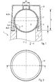
- Fig.1 shows a section through a first preferred embodiment of the upper part of a designed as a deodorant embodiment.
- the container 1 for receiving a liquid comprises the container casing 2, a discharge opening 3 arranged in the container casing 2, a support and holding unit 4 arranged on the container casing 2, which encloses a flow channel 5 connected to a discharge opening 3 (indicated by a horizontal dashed line) , a ball 6 arranged in the supporting and holding unit 4, which can close the flow channel 5 with respect to the surroundings of the container 1, and three contact areas 7a, 7b, 7c between the supporting and holding unit 4 and the ball 6.
- the container 1 has a cap 20 which is detachably connected to the container casing 2 and the ball 6 along the extending through the supporting and holding unit 4 longitudinal axis L in the direction of not shown, but indicated by an arrow and numeral 12, receiving space the container 1 presses, in this illustration thus down.
- a cap 20 which is detachably connected to the container casing 2 and the ball 6 along the extending through the supporting and holding unit 4 longitudinal axis L in the direction of not shown, but indicated by an arrow and numeral 12, receiving space the container 1 presses, in this illustration thus down.
- the above the center of the ball 6 arranged contact area 7a is formed as a support and holding portion 8a.
- the first contact area 7a also serves as a sealing area.
- the second contact portion 7b and the third contact portion 7c are spaced from each other with respect to the vertical longitudinal axis L in the figure.
- the second contact region 7b serves as a sealing region 9
- the third contact region 7c serves as a supporting and holding region 8b.
- the supporting and holding portions 8a, 8b support the ball 6 against gravity and against the contact force when applying the deodorant fluid and the force through the screwed closure.
- the support and holding unit 4 has a sleeve whose upper end extends upward beyond the center of the ball 6 into the first contact area 7a.
- Fig. 1 is indicated that the supporting and holding unit 4 in the second contact region 7b or sealing region 9 has a circumferential projection 10 which extends substantially parallel to the longitudinal axis L.
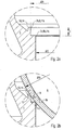
- Fig. 2a and 2b show details of the container Fig. 1 , what a Fig. 1 marked with X. Shown are a section through the supporting and holding unit 4 and two contact areas 7b, 7c.
- the second contact region 7b is designed as a sealing region 9 and the third contact region 7c as a supporting and holding region 8b.
- the supporting and holding unit 4 has a projection 10 which extends substantially parallel to the longitudinal axis L.
- the projection 10 has the boundary edge 11b.
- the wall thickness of the projection 10 in cross section is small, the projection 10 thus slim. Due to the slim shape of the projection 10 can be easily deformed by the ball 6, in particular elastic and almost completely reversible. Thus, mechanical stresses in the projection 10 due to a deformation or bending, in particular by the ball 6, are kept low.
- a favorable material in particular a polymer such as polypropylene or polyethylene, can also be used for the projection 10.
- the supporting and holding unit 4 is formed with a boundary edge 11c, with a substantially rectangular step and with an annular surface, which is arranged substantially perpendicular to the longitudinal axis L by the supporting and holding unit 4.
- This compared to the projection 10 rather massive design of the wall of the supporting and holding unit 4 in the supporting and holding area 8b allows the improved transmission of supporting forces or for supporting the ball. 6
- Fig. 2a the ball 6 is not shown and the projection 10 is undeformed.
- Fig. 2b the ball 6 rests on the boundary edge 11c, and the second portion 14 of the projection 10 is elastically deformed or elastically expanded (deformed state). The second portion 14 abuts the ball 6, whereby the seal is improved.
- Fig. 3 shows a different view on the detail of the Fig. 2a , Shown is the annular surface of the shoulder in the wall of the support and holding unit in the support and holding area 8b.
- Fig. 4a shows a section through a second preferred embodiment of the upper part of a designed as a deodorant embodiment.
- the supporting and holding region 8b and the sealing region 9 are opposite the container Fig. 1 and 2 in the order of their arrangement along the longitudinal axis L reversed.
- the second contact area 7b which is closer to the discharge opening 3 serves as the support and holding area 8b
- the third contact area 7c which is further away from the discharge opening 3, acts as the sealing area 9.
- the first contact region 7a is furthermore designed as a supporting and holding region 8a and has in the embodiment according to FIG Fig. 4a a radially inwardly directed retaining ring with a very small extent in the axial direction. This results in a very small contact surface between the supporting and holding unit 4 and the ball. 6
- Fig. 4b shows details of the container Fig. 4a , what a Fig. 4a marked with X. In it - as well as in Fig. 4a - The sealing portion 9 is shown in an undeformed and therefore the ball 6 in the representation penetrating state.
Landscapes
- Closures For Containers (AREA)
- Disinfection, Sterilisation Or Deodorisation Of Air (AREA)
- Packaging Of Annular Or Rod-Shaped Articles, Wearing Apparel, Cassettes, Or The Like (AREA)
Description
- Die vorliegende Erfindung betrifft einen Behälter zur Aufnahme eines fließfähigen Fluids mit einem Behältermantel, einer in dem Behältermantel angeordneten Ausgabeöffnung, eine am Behältermantel angeordnete Abstütz- und Halteeinheit, welche einen mit der Ausgabeöffnung verbundenen Strömungskanal umschließt, sowie eine in der Abstütz- und Halteeinheit angeordnete Kugel.
Derartige Behälter werden üblicherweise verwendet, um eine Flüssigkeit oder eine pastöse Substanz auf eine Fläche aufzubringen, siehe beispielsweise dieEP 1 673 998 A1 . Besonders bekannt ist die Verwendung solcher Behälter als sogenannte Deoroller oder Roll-On-Deos zum Aufbringen eines deodorierenden Fluids auf die menschliche Haut. Die vorliegende Erfindung wird nachfolgend am Beispiel eines solchen Deorollers beschrieben, dies ist aber nicht als Einschränkung in der Anwendung der Erfindung zu verstehen.
Um das im Behälter befindliche Fluid auf die Haut auftragen zu können, muss die beweglich gehaltene Kugel mit der Flüssigkeit benetzt werden. Wird der Deoroller in einer Position aufbewahrt, in der sich die Kugel über dem Fluid befindet, muss der Deoroller zum Auftragen in eine Position gebracht werden, in der sich die Kugel unterhalb des Fluids befindet, so dass die Kugel bei der Drehbewegung Fluid aufnehmen und wieder an die Haut abgeben kann. Vom Benutzer wird es in der Regel allerdings als angenehmer empfunden, wenn der Deoroller von vorneherein in einer Position aufbewahrt wird, in der sich die Kugel unterhalb des Fluids befindet. In diesem Fall ist die Kugel bereits mit dem Fluid benetzt und der Auftrag kann schneller erfolgen. - Bei beiden Bauformen, insbesondere aber bei der letzten Bauform mit der unten angeordneten Kugel, muss dafür Sorge getragen werden, dass die Ausgabeöffnung des Behälters durch die Kugel gut abgedichtet ist, um bei oben angeordneter Kugel ein Austrocknen der Flüssigkeit und bei unten angeordneter Kugel ein Auslaufen der Flüssigkeit zu vermeiden.
- Bei der Konstruktion einer geeigneten Abdichteinrichtung ist, wie bei der Konstruktion des gesamten Deorollers, zu berücksichtigen, dass dieser üblicherweise oder häufig nicht wieder nachgefüllt wird und nach der Entleerung weggeworfen wird. Aus Gründen des Umweltschutzes muss deshalb dafür Sorge getragen werden, dass möglichst wenig Material für den Behälter selbst verwendet werden muss, und dass dieses Material zudem auch erhöhten Anforderungen an das Recycling bzw. die biologische Abbaubarkeit genügen muss. Dabei spielen natürlich auch die Kosten für die Produktion und für den Abfüllvorgang selbst eine erhebliche Rolle.
- Der vorliegenden Erfindung liegt deshalb die Aufgabe zugrunde, einen Behälter der eingangs genannten Art zu schaffen, der eine gute Abdichtung des Flüssigkeitsvolumens ermöglicht.
- Diese Aufgabe wird erfindungsgemäß durch den Gegenstand des Anspruchs 1 gelöst. Zu bevorzugende Weiterbildungen sind Gegenstand der Unteransprüche.
- Der erfindungsgemäße Behälter dient der Aufnahme einer Flüssigkeit bzw. eines Fluids und weist einen Behältermantel auf. Eine in dem Behältermantel angeordnete Ausgabeöffnung dient der Abgabe der Flüssigkeit aus dem Behälter bzw. Behälterinneren an dessen Umgebung. Am Behältermantel ist eine Abstütz- und Halteeinheit angeordnet, welche einen mit der Ausgabeöffnung verbundenen Strömungskanal umschließt. In der Abstütz- und Halteeinheit ist eine Kugel beweglich angeordnet, deren Formgebung zumindest im Wesentlichen der idealen geometrischen Form angenähert ist. Die Kugel schließt diesen Strömungskanal im Wesentlichen gegenüber der Umgebung des Behälters ab. Zwischen der Abstütz- und Halteeinheit und der Kugel sind wenigstens drei Kontaktbereiche ausgebildet, welche um die Kugel umlaufen und im Wesentlichen parallel zueinander ausgebildet sind.
- Ein erster Kontaktbereich bewirkt die Übertragung von Kräften zwischen der Kugel und der Abstütz- und Halteeinheit (Stützkräfte), welche der Abstützung der Kugel insbesondere während der Benutzung des Behälters dienen (Stützfunktion). Wenigstens ein weiterer der Kontaktbereiche (Dichtbereich) dient zur Abdichtung (Dichtfunktion) zwischen der Abstütz- und Halteeinheit und der Kugel, im Wesentlichen aber nicht zur Übertragung von Stützkräften. Daher kann im Dichtbereich ein Wandabschnitt der Abstütz- und Halteeinheit dazu ausgebildet sein, an der Kugel anzuliegen und sich dabei lediglich elastisch zu verformen.
- Unter einem Behältermantel ist im Sinne der Erfindung eine Wandung des Behälters zu verstehen, welche einen Aufnahmeraum des Behälters gegenüber der Umgebung begrenzen und einem Austausch von Stoffen zwischen dem Aufnahmeraum und der Umgebung entgegenwirken kann. Vorzugsweise ist der Behältermantel wenigstens abschnittsweise rotationssymmetrisch, mit einem Polymer ausgebildet und/oder mittels Spritzblasen, Extrusionsblasformen oder einem ähnlichen Verfahren hergestellt.
- Unter einer Ausgabeöffnung ist im Sinne der Erfindung eine Öffnung im Behältermantel zu verstehen, welche der gerichteten Abgabe der vom Aufnahmeraum aufgenommenen Flüssigkeit an die Umgebung des Behälters dient. Vorzugsweise ist die Ausgabeöffnung senkrecht zu einer Längsachse des Behälters angeordnet und/oder im Wesentlichen kreisförmig ausgebildet.
- Unter einer Abstütz- und Halteeinheit ist im Sinne der Erfindung eine Einheit zu verstehen, welche am Behältermantel angeordnet ist und zum Abstützen bzw. zum Halten der Kugel dient. Abstützen und Halten der Kugel erfolgt derart, dass diese innerhalb der Abstütz- und Halteeinheit drehbeweglich ist. Vorzugsweise ist die Abstütz- und Halteeinheit mit dem Material des Behältermantels ausgebildet, mit dem Behältermantel stoffschlüssig verbunden und/oder einstückig mit dem Behältermantel ausgebildet.
- Unter einem Strömungskanal ist im Sinne der Erfindung ein Kanal zu verstehen, welcher der Führung der vom Aufnahmeraum aufgenommenen Flüssigkeit in Richtung der Ausgabeöffnung dient. So erstreckt sich der Strömungskanal wenigstens zwischen dem Aufnahmeraum und der Ausgabeöffnung. Der Strömungskanal ist von der Abstütz- und Halteeinheit wenigstens teilweise umschlossen.
- Unter einer Kugel ist im Sinne der Erfindung ein im Wesentlichen rotationssymmetrischer Körper zu verstehen, welcher zeitweise zur Bereitstellung der Flüssigkeit aus dem Aufnahmeraum an die Umgebung dient. Gemeinsam mit der Abstütz- und Halteeinheit dient die Kugel zeitweise zur Abdichtung des Behälters bzw. der Ausgabeöffnung bzw. des Strömungskanals. Vorzugsweise weist die Kugel einen Durchmesser zwischen 25 und 45 mm oder zwischen 20 und 45 mm, besonders bevorzugt zwischen 22 und 28 oder zwischen 30 und 38 mm auf.
- Unter einem Kontaktbereich ist im Sinne der Erfindung ein Bereich zu verstehen, in welchem die Abstütz- und Halteeinheit die Kugel mechanisch berühren kann. Der Begriff "mechanisch berühren" umfasst auch den Fall, dass sich zwischen den Kontaktpartner ein Flüssigkeitsfilm befindet. Während der Benutzung und Lagerung des Behälters können die Kontaktbereiche sich entlang der Kugeloberfläche verlagern. Vorzugsweise ist einer der Kontaktbereiche benachbart zu der Ausgabeöffnung angeordnet.
- Nachfolgend werden bevorzugte Weiterbildungen des Behälters beschrieben, die jeweils miteinander kombiniert werden können, soweit es nicht ausdrücklich ausgeschlossen wird. Erfindungsgemäß sind wenigstens zwei Kontaktbereiche als Abstütz- und Haltebereiche ausgebildet und wenigstens ein Kontaktbereich als Dichtbereich. Die Abstütz- und Haltebereiche wirken einem Austritt der Kugel aus der Abstütz- und Halteeinheit in die Umgebung sowie in Richtung des Aufnahmeraums entgegen. Innerhalb der Abstütz- und Haltebereiche können Stützkräfte zwischen der Kugel und der Abstütz- und Halteeinheit übertragen werden. Der Dichtbereich dient zur Abdichtung zwischen der Abstütz- und Halteeinheit und der Kugel, im Wesentlichen aber nicht zur Übertragung von Stützkräften. Durch Aufteilung von Stützfunktion und Dichtfunktion auf unterschiedliche Kontaktbereiche können diese Kontaktbereiche besser an die jeweilige Funktion angepasst werden. Besonders vorteilhaft ist, dass kleinere Dichtkräfte auftreten, da die Stützkräfte nicht im Dichtbereich aufgenommen werden müssen und dass deshalb geringere Verformungskräfte auftreten. Da günstige Kunststoffmaterialien dazu neigen, sich zu setzen, kann dadurch erreicht werden, dass auch bei kostengünstigen Materialien eine sich über einen langen Zeitraum erstreckende Dichtwirkung gewährleistet ist.
Gemäß einer bevorzugten Weiterbildung kann die Abstütz- und Halteeinheit in einem der Abstütz- und Haltebereiche einen insbesondere umlaufenden Absatz, insbesondere mit einer Begrenzungskante, aufweisen, welcher als Sitz der Kugel dienen kann, gegen welchen die Kugel gedrückt werden kann. Vorzugsweise ist der Absatz zur Aufnahme von Stützkräften mechanisch ausreichend stabil bzw. steif ausgestaltet. Damit wird die Abdichtung verbessert.
Gemäß einer bevorzugten Weiterbildung sind wenigstens zwei Kontaktbereiche als Abstütz- und Haltebereiche und wenigstens zwei Kontaktbereiche als Dichtbereiche ausgebildet. Dabei dient ein zur Ausgabeöffnung benachbarter Kontaktbereich sowohl als Abstütz- und Haltebereich als auch als Dichtbereich und leistet sowohl die Stützfunktion als auch die Dichtfunktion. An dem der Ausgabeöffnung gegenüberliegenden Ende der Abstütz- und Halteeinheit sind sowohl ein Abstütz- und Haltebereich als auch ein von diesem Abstütz- und Haltebereich räumlich getrennter Dichtbereich angeordnet. Durch diese Trennung kann der Dichtbereich von der Stützfunktion befreit werden. Zudem können Kräfte, welche während der Anwendung des Behälters die Kugel in Richtung des Aufnahmeraum drücken, durch den separaten Abstütz- und Haltebereich besser aufgenommen werden. Erfindungsgemäß ist wenigstens einer der Dichtbereiche, mit wenigstens einem Vorsprung ausgebildet, welcher in der Abstütz- und Halteeinheit umlaufend angeordnet ist und auf dem die Kugel zumindest in einer der beiden möglichen Vertikalpositionen aufliegt.
Gemäß einer bevorzugten Weiterbildung ist der wenigstens eine Vorsprung mit einer umlaufenden Begrenzungskante ausgebildet. Diese Begrenzungskante dient der mechanischen Berührung der Kugel entlang einer Kreislinie.
Gemäß einer bevorzugten Weiterbildung ist der wenigstens eine Vorsprung mit einer Wandung der Abstütz- und Halteeinheit stoffschlüssig verbunden oder einstückig ausgebildet. Damit können Fertigungskosten verringert werden.
Die Abstütz- und Halteeinheit kann aber auch mehrstückig ausgebildet sein, wobei wenigstens ein Kontaktbereich oder dessen Vorsprung vorzugsweise als Einsatz ausgebildet ist.
Gemäß einer bevorzugten Weiterbildung erstreckt sich ein im Wesentlichen hohlzylindrischer erster Abschnitt des wenigstens einen Vorsprungs parallel zu einer durch die Abstütz- und Halteeinheit verlaufenden Längsachse. - Gemäß einer bevorzugten Weiterbildung ist ein zweiter Abschnitt des wenigstens einen Vorsprungs, insbesondere durch die Kugel, elastisch verformbar bzw. elastisch aufweitbar. Dabei kann der zweite Abschnitt elastisch, also umkehrbar, aus seinem unverformten Zustand in seinen verformten Zustand überführt werden. Wegen der lediglich elastischen Verformung bzw. Aufweitung kann die Rückstellung des zweiten Abschnitts im Wesentlichen vollständig sein. Vorzugsweise ist der zweite Abschnitt einstückig mit dem ersten Abschnitt des Vorsprungs ausgebildet. Dadurch kann das Rückstellvermögen des Vorsprungs verbessert sein. Vorzugsweise ist der Vorsprung mit Polypropylen oder Polyethylen ausgebildet. Besonders bevorzugt ist der gesamte Behälter und Abstütz- und Halteeinheit einstückig aus Polypropylen oder Polyethylen ausgebildet. Aber auch andere Kunststoffe kommen hierfür in Frage. Erfindungsgemäß ist wenigstens einer der Dichtbereiche mit einem vorbestimmten Abstand C entlang einer durch die Abstütz- und Halteeinheit verlaufenden Längsachse L von einem der Abstütz- und Haltebereiche beabstandet. Vorzugsweise beträgt der Abstand mehr als 1 mm. Vorzugsweise beträgt der Abstand entlang einer durch die Abstütz- und Halteeinheit verlaufenden Längsachse L zwischen einer Begrenzungskante wenigstens eines Vorsprungs eines der Dichtbereiche und einer Begrenzungskante eines der Abstütz- und Haltebereiche mehr als 1 mm. Gemäß einer bevorzugten Weiterbildung weist der Behälter eine Kappe auf, welche mit dem Behältermantel oder mit der Abstütz- und Halteeinheit lösbar verbunden ist. Dabei kann die Kugel gegen einen Absatz oder Vorsprung der Abstütz- und Halteeinheit gedrückt werden. Damit kann die Abdichtung verbessert werden.
- Weitere Vorteile, Merkmale und Anwendungsmöglichkeiten der vorliegenden Erfindung ergeben sich aus der nachfolgenden Beschreibung in Zusammenhang mit den Figuren. Es zeigen:
- Fig. 1
- einen Schnitt durch eine erste bevorzugte Weiterbildung des Behälters,
- Fig. 2a und 2b
- Details des Behälters der
Fig. 1 , - Fig. 3
- eine andere Ansicht auf das Detail der
Fig. 2a , - Fig. 4a
- einen Schnitt durch eine zweite bevorzugte Weiterbildung des Behälters und
- Fig. 4b
- Details des Behälters der
Fig. 4a . -
Fig.1 zeigt einen Schnitt durch eine erste bevorzugte Ausgestaltung des oberen Teils eines als Deoroller gestalteten Ausführungsbeispiels. - Der Behälter 1 zur Aufnahme einer Flüssigkeit weist den Behältermantel 2 auf, eine in dem Behältermantel 2 angeordnete Ausgabeöffnung 3, eine am Behältermantel 2 angeordnete Abstütz- und Halteeinheit 4, welche einen mit einer Ausgabeöffnung 3 (angedeutet als horizontale gestrichelte Linie) verbundenen Strömungskanal 5 umschließt, eine in der Abstütz- und Halteeinheit 4 angeordnete Kugel 6, welche den Strömungskanal 5 gegenüber der Umgebung des Behälters 1 abschließen kann, sowie drei Kontaktbereiche 7a, 7b, 7c zwischen der Abstütz- und Halteeinheit 4 und der Kugel 6.
- Zusätzlich weist der Behälter 1 eine Kappe 20 auf, welche lösbar mit dem Behältermantel 2 verbunden ist und die Kugel 6 entlang der durch die Abstütz- und Halteeinheit 4 verlaufende Längsachse L in Richtung des nicht dargestellten, aber mit einem Pfeil und Ziffer 12 angedeuteten, Aufnahmeraums des Behälters 1 drückt, in dieser Darstellung somit nach unten. Damit kann die Abdichtung des Behälters 1 bei Nichtgebrauch verbessert werden.
- Der oberhalb des Mittelpunkts der Kugel 6 angeordnete Kontaktbereich 7a, nachfolgend erster Kontaktbereich 7a genannt, ist als Abstütz- und Haltebereich 8a ausgebildet. In einer besonderen Ausgestaltung, die in
Fig. 1 nicht dargestellt ist, dient der erste Kontaktbereich 7a auch als Dichtbereich. Unterhalb des Mittelpunkt der Kugel 6 sind der zweite Kontaktbereich 7b und der dritte Kontaktbereich 7c voneinander bezüglich der in der Figur vertikalen Längsachse L beabstandet. Der zweite Kontaktbereich 7b dient als Dichtbereich 9 und der dritte Kontaktbereich 7c als Abstütz- und Haltebereich 8b. Die Abstütz- und Haltebereiche 8a, 8b stützen die Kugel 6 gegen die Schwerkraft und gegen die Kontaktkraft beim Auftragen der Deoflüssigkeit und die Kraft durch den aufgeschraubten Verschluss ab. - Die Abstütz- und Halteeinheit 4 weist eine Hülse auf, deren oberes Ende nach oben über den Mittelpunkt der Kugel 6 hinaus bis in den ersten Kontaktbereich 7a reicht.
- In
Fig. 1 ist angedeutet, dass die Abstütz- und Halteeinheit 4 im zweiten Kontaktbereich 7b bzw. Dichtbereich 9 einen umlaufenden Vorsprung 10 aufweist, welcher sich im Wesentlichen parallel zur Längsachse L erstreckt. -
Fig. 2a und 2b zeigen Details des Behälters derFig. 1 , welche inFig. 1 mit X markiert sind. Gezeigt sind ein Schnitt durch die Abstütz- und Halteeinheit 4 sowie zwei Kontaktbereiche 7b, 7c. Der zweite Kontaktbereich 7b ist als Dichtbereich 9 und der dritte Kontaktbereich 7c als Abstütz- und Haltebereich 8b ausgebildet. - Im Dichtbereich 9 weist die Abstütz- und Halteeinheit 4 einen Vorsprung 10 auf, welcher sich im Wesentlichen parallel zur Längsachse L erstreckt. Der Vorsprung 10 weist die Begrenzungskante 11b auf. Im Vergleich zum Maß C, mit welchem sich der Vorsprung 10 parallel zur Längsachse L erstreckt, ist die Wandstärke des Vorsprungs 10 im Querschnitt gering, der Vorsprung 10 somit schlank. Durch die schlanke Gestalt kann der Vorsprung 10 einfacher durch die Kugel 6 verformt werden, insbesondere elastisch und nahezu vollständig umkehrbar. Damit können mechanische Spannungen im Vorsprung 10 infolge einer Verformung bzw. Biegung, insbesondere durch die Kugel 6, gering gehalten werden. Dadurch kann für den Vorsprung 10 auch ein günstiger Werkstoff, insbesondere ein Polymer wie Polypropylen oder Polyethylen, verwendet werden.
- Im Abstütz- und Haltebereich 8b ist die Abstütz- und Halteeinheit 4 mit einer Begrenzungskante 11c, mit einem im wesentlichen rechtwinkligen Absatz und mit einer ringförmigen Fläche, welche im Wesentlichen senkrecht zu der Längsachse L durch die Abstütz- und Halteeinheit 4 angeordnet ist, ausgebildet. Diese im Vergleich zum Vorsprung 10 eher massive Gestaltung der Wandung der Abstütz- und Halteeinheit 4 im Abstütz- und Haltebereich 8b ermöglicht die verbesserte Übertragung von Stützkräften bzw. zur Abstützung der Kugel 6.
- Durch die Aufteilung von Stützfunktion und Dichtfunktion auf unterschiedliche Kontaktbereiche 7a, 7b, 7c kann deren Gestaltung besser an die jeweilige Funktion angepasst sein.
- In
Fig. 2a ist die Kugel 6 nicht gezeigt und der Vorsprung 10 ist unverformt. InFig. 2b hingegen liegt die Kugel 6 auf der Begrenzungskante 11c auf und der zweite Abschnitt 14 des Vorsprungs 10 ist elastisch verformt bzw. elastisch aufgeweitet (verformter Zustand). Der zweite Abschnitt 14 liegt an der Kugel 6 an, wodurch die Abdichtung verbessert ist. -
Fig. 3 zeigt eine andere Ansicht auf das Detail derFig. 2a . Dargestellt ist die ringförmige Fläche des Absatzes in der Wandung der Abstütz- und Halteeinheit im Bereich Abstütz- und Haltebereichs 8b. -
Fig. 4a zeigt einen Schnitt durch eine zweite bevorzugte Ausgestaltung des oberen Teils eines als Deoroller gestalteten Ausführungsbeispiels. Darin sind der Abstütz- und Haltebereich 8b und der Dichtbereich 9 gegenüber dem Behälter ausFig. 1 und2 in der Reihenfolge ihrer Anordnung entlang der Längsachse L vertauscht. In dieser Ausgestaltung dient daher der zweite, näher an der Ausgabeöffnung 3 liegende Kontaktbereich 7b als Abstütz- und Haltebereich 8b und der dritte, weiter entfernt von der Ausgabeöffnung 3 liegende Kontaktbereich 7c als Dichtbereich 9. - Der erste Kontaktbereich 7a ist weiterhin als Abstütz- und Haltebereich 8a ausgebildet und weist in der Ausgestaltung gemäß
Fig. 4a einen radial nach innen gerichteten Haltering mit einer sehr geringen Ausdehnung in axialer Richtung auf. Dadurch ergibt sich eine sehr geringe Berührungsfläche zwischen der Abstütz- und Halteeinheit 4 und der Kugel 6. -
Fig. 4b zeigt Details des Behälters derFig. 4a , welche inFig. 4a mit X markiert sind. Darin - wie auch inFig. 4a - ist der Dichtbereich 9 in einem nicht verformten und daher die Kugel 6 in der Darstellung durchdringenden Zustand gezeigt. - Da in dem in
Fig. 4b dargestellten Querschnitt die Tangente der Kugel 6 am Kontaktbereich 7c und damit am Dichtbereich 9 einen größeren Winkel mit der Längsachse L einschließt als am Kontaktbereich 7b (an welchem der Dichtbereich in der Ausgestaltung gemäßFig. 1 angeordnet ist), ist auch die Form des Vorsprungs 10 im Dichtbereich 9 gegenüber jener inFig. 1 verschieden. Der Vorsprung 10 steht im Wesentlichen in radialer Richtung der Kugel nach innen aus der Abstütz- und Halteeinheit 4 hervor und läuft nach innen zu seiner Begrenzungskante 11c hin spitz zu. Liegt die Kugel 6 auf der Begrenzungskante 11c auf, so ist der zweite Abschnitt 14 des Vorsprungs 10 elastisch verformt. Die Auflagefläche der Begrenzungskante 11c wird dabei im Wesentlichen von der abgerundeten Seite des zweiten Abschnitts 14 des Vorsprungs 10 gebildet. - Bevorzugt sind in etwa folgende Abmessungen und Materialien:
- Material: Polypropylen oder Polyethylen für Behälter und Abstützeinrichtung
- Kugeldurchmesser von 25 bis 45 mm oder 20 bis 45 mm, besonders bevorzugt 22 bis 28 oder 30 bis 38 mm
- Höhe des Vorsprungs (Maß C in
Fig. 2a ) erfindungsgemäß von 1 bis 2 mm - Wandstärke des Vorsprungs 0,1 bis 0,5 mm
-
- 1
- Behälter
- 2
- Behältermantel
- 3
- Ausgabeöffnung
- 4
- Abstütz- und Halteeinheit
- 5
- Strömungskanal
- 6
- Kugel
- 7a
- Erster Kontaktbereich
- 7b
- Zweiter Kontaktbereich
- 7c
- Dritter Kontaktbereich
- 8a, 8b
- Abstütz- und Haltebereiche
- 9
- Dichtbereich
- 10
- Vorsprung
- 11b, 11c
- Begrenzungskanten
- 12
- Aufnahmeraum
- 13
- Erster Abschnitt des Vorsprungs
- 14
- Zweiter Abschnitt des Vorsprungs
- 20
- Kappe
- L
- Längsachse
- C
- Abstand zwischen zwei Begrenzungskanten bzw. Höhe des Vorsprungs
Claims (11)
- Behälter (1) zur Aufnahme einer Flüssigkeit mit:einem Behältermantel (2),einer in dem Behältermantel (2) angeordneten Ausgabeöffnung (3),einer am Behältermantel (2) angeordneten Abstütz- und Halteeinheit (4), welche einen mit der Ausgabeöffnung (3) verbundenen Strömungskanal (5) umschließt, undeiner in der Abstütz- und Halteeinheit (4) drehbeweglich angeordneten Kugel (6), deren Formgebung zumindest im Wesentlichen der idealen geometrischen Form angenähert ist und die diesen Strömungskanal (5) gegenüber der Umgebung des Behälters (1) abschließen kann,wobei zwischen der Abstütz- und Halteeinheit (4) und dieser Kugel (6) wenigstens drei Kontaktbereiche (7) ausgebildet sind, welche um die Kugel (6) umlaufen und im Wesentlichen parallel zueinander ausgebildet sind,wobei wenigstens zwei Kontaktbereiche (7) als Abstütz- und Haltebereiche (8) ausgebildet sind und wenigstens ein Kontaktbereich (7) als Dichtbereich (9),wobei wenigstens einer der Dichtbereiche (9) mit wenigstens einem Vorsprung (10) ausgebildet ist, welcher in der Abstütz- und Halteeinheit (4) umlaufend angeordnet ist und auf dem die Kugel (6) zumindest in einer der beiden möglichen Vertikalpositionen des Behälters aufliegt, undwobei wenigstens einer der Dichtbereiche (9) mit einem vorbestimmten Abstand (C) entlang einer durch die Abstütz- und Halteeinheit (4) verlaufenden Längsachse (L) von einem der Abstütz- und Haltebereiche (8) beabstandet ist,dadurch gekennzeichnet, dassdie Höhe (C) des Vorsprungs zwischen 1 und 2 mm beträgt.
- Behälter (1) nach Anspruch 1, dadurch gekennzeichnet, dass wenigstens zwei Kontaktbereiche (7) als Abstütz- und Haltebereiche (8) und wenigstens zwei Kontaktbereiche (7) als Dichtbereiche (9) ausgebildet sind.
- Behälter (1) nach wenigstens einem der vorhergehenden Ansprüche, dadurch gekennzeichnet, dass der wenigstens eine Vorsprung (10) mit einer umlaufenden Begrenzungskante (11) ausgebildet ist.
- Behälter (1) nach wenigstens einem der vorhergehenden Ansprüche, dadurch gekennzeichnet, dass der wenigstens eine Vorsprung (10) einstückig mit der Abstütz- und Halteeinheit (4) ausgebildet ist.
- Behälter (1) nach wenigstens einem der vorhergehenden Ansprüche, dadurch gekennzeichnet, dass ein im Wesentlichen hohlzylindrischer erster Abschnitt (13) des wenigstens einen Vorsprungs (10) sich parallel zu einer durch die Abstütz- und Halteeinheit (4) verlaufenden Längsachse (L) erstreckt.
- Behälter (1) nach wenigstens einem der vorhergehenden Ansprüche, dadurch gekennzeichnet, dass ein zweiter Abschnitt (14) des wenigstens einen Vorsprungs (10), insbesondere durch die Kugel (6), elastisch verformbar bzw. elastisch aufweitbar ist.
- Behälter (1) nach wenigstens einem der vorhergehenden Ansprüche, dadurch gekennzeichnet, dass der wenigstens eine Vorsprung (10) innerhalb eines der Dichtbereiche (9) angeordnet ist und abschnittweise, insbesondere mit seinem zweiten Abschnitt (14), an der Kugel (6) anliegen kann.
- Behälter (1) nach wenigstens einem der vorhergehenden Ansprüche, dadurch gekennzeichnet, dass einer der zweiten Abschnitte (14) des wenigstens einen Vorsprungs (10) die Kugel (6) entlang einer durch die Abstütz- und Halteeinheit (4) verlaufenden Längsachse (L) in Richtung eines der Abstütz- und Haltebereiche (8) drücken kann.
- Behälter (1) nach wenigstens einem der vorhergehenden Ansprüche, dadurch gekennzeichnet, dass einer der Dichtbereiche (9) entlang einer durch die Abstütz- und Halteeinheit (4) verlaufenden Längsachse (L) zwischen zwei weiteren Kontaktbereichen (7) angeordnet ist.
- Behälter (1) nach wenigstens einem der vorhergehenden Ansprüche, gekennzeichnet durch eine Kappe (20), welche mit dem Behältermantel (2) lösbar verbunden ist, welche die Kugel (6) von der Ausgabeöffnung (3) weg drücken kann.
- Behälter (1) nach wenigstens einem der vorhergehenden Ansprüche, dadurch gekennzeichnet, dass die Wandstärke des Vorsprungs zwischen 0,1 und 0,5 mm beträgt.
Priority Applications (1)
| Application Number | Priority Date | Filing Date | Title |
|---|---|---|---|
| PL15706676T PL3197310T3 (pl) | 2014-09-23 | 2015-02-16 | Pojemnik do przyjmowania ciekłego płynu |
Applications Claiming Priority (2)
| Application Number | Priority Date | Filing Date | Title |
|---|---|---|---|
| DE202014007748.7U DE202014007748U1 (de) | 2014-09-23 | 2014-09-23 | Behälter zur Aufnahme eines fließfähigen Fluids |
| PCT/EP2015/000340 WO2016045756A1 (de) | 2014-09-23 | 2015-02-16 | Behälter zur aufnahme eines fliessfähigen fluids |
Publications (2)
| Publication Number | Publication Date |
|---|---|
| EP3197310A1 EP3197310A1 (de) | 2017-08-02 |
| EP3197310B1 true EP3197310B1 (de) | 2018-06-27 |
Family
ID=52595258
Family Applications (1)
| Application Number | Title | Priority Date | Filing Date |
|---|---|---|---|
| EP15706676.2A Active EP3197310B1 (de) | 2014-09-23 | 2015-02-16 | Behälter zur aufnahme eines fliessfähigen fluids |
Country Status (10)
| Country | Link |
|---|---|
| US (1) | US10306968B2 (de) |
| EP (1) | EP3197310B1 (de) |
| BR (1) | BR112017003285B8 (de) |
| DE (1) | DE202014007748U1 (de) |
| ES (1) | ES2636945T3 (de) |
| MX (1) | MX382179B (de) |
| PL (1) | PL3197310T3 (de) |
| RU (1) | RU2668187C1 (de) |
| WO (1) | WO2016045756A1 (de) |
| ZA (1) | ZA201700815B (de) |
Family Cites Families (7)
| Publication number | Priority date | Publication date | Assignee | Title |
|---|---|---|---|---|
| GB1166033A (en) * | 1966-08-13 | 1969-10-01 | Fisons Pharmaceuticals Ltd | Ball Top Applicators for Dispensing Liquids |
| US4221495A (en) * | 1979-01-29 | 1980-09-09 | W. Braun Company | Roll-on applicator with sharp sealing ring |
| IT238123Y1 (it) * | 1997-12-16 | 2000-09-29 | Gibo Italia Srl | Capsula per il dosaggio controllato di prodotti contenuti inflaconi od analoghi contenitori |
| FR2879904A1 (fr) * | 2004-12-23 | 2006-06-30 | Oreal | Ensemble de conditionnement et d'application d'une produit cosmetique |
| BRPI0600990A8 (pt) * | 2006-03-21 | 2016-11-01 | Arcuri Neto Leonardo | Sistema de vedação para embalagem |
| ES2527850T3 (es) * | 2011-02-03 | 2015-01-30 | Weener Plastik Gmbh | Caperuza de cierre para un recipiente de fluidos y procedimiento para su producción |
| DE202013000328U1 (de) * | 2013-01-14 | 2013-01-23 | Jürgen Schmidt | Austragvorrichtung für fließfähige Medien |
-
2014
- 2014-09-23 DE DE202014007748.7U patent/DE202014007748U1/de not_active Expired - Lifetime
-
2015
- 2015-02-16 MX MX2017003714A patent/MX382179B/es unknown
- 2015-02-16 RU RU2017107964A patent/RU2668187C1/ru active
- 2015-02-16 WO PCT/EP2015/000340 patent/WO2016045756A1/de not_active Ceased
- 2015-02-16 BR BR112017003285A patent/BR112017003285B8/pt active IP Right Grant
- 2015-02-16 EP EP15706676.2A patent/EP3197310B1/de active Active
- 2015-02-16 PL PL15706676T patent/PL3197310T3/pl unknown
- 2015-02-16 ES ES15706676.2T patent/ES2636945T3/es active Active
- 2015-02-16 US US15/512,238 patent/US10306968B2/en active Active
-
2017
- 2017-02-02 ZA ZA2017/00815A patent/ZA201700815B/en unknown
Non-Patent Citations (1)
| Title |
|---|
| None * |
Also Published As
| Publication number | Publication date |
|---|---|
| US10306968B2 (en) | 2019-06-04 |
| US20170290405A1 (en) | 2017-10-12 |
| ZA201700815B (en) | 2020-09-30 |
| BR112017003285B8 (pt) | 2022-05-10 |
| BR112017003285A2 (pt) | 2017-11-28 |
| BR112017003285B1 (pt) | 2022-04-05 |
| MX382179B (es) | 2025-03-13 |
| ES2636945T1 (es) | 2017-10-10 |
| DE202014007748U1 (de) | 2016-01-08 |
| EP3197310A1 (de) | 2017-08-02 |
| PL3197310T3 (pl) | 2018-12-31 |
| WO2016045756A8 (de) | 2016-06-02 |
| MX2017003714A (es) | 2017-06-30 |
| ES2636945T3 (es) | 2018-11-08 |
| WO2016045756A1 (de) | 2016-03-31 |
| RU2668187C1 (ru) | 2018-09-26 |
Similar Documents
| Publication | Publication Date | Title |
|---|---|---|
| EP2509718B1 (de) | Kartuschenkolben | |
| EP2198970B1 (de) | Kartuschenkolben | |
| EP3140213B1 (de) | Zumisch-verschlussvorrichtung für einen behälter | |
| DE69208849T2 (de) | Vorrichtung zum auftragen von flüssigkeiten, insbesondere von kosmetischen produkten | |
| EP2640222B1 (de) | Kosmetikeinheit mit quetschbarem vorratsbehälter | |
| EP2478961B1 (de) | Universelle Verschlussvorrichtung | |
| EP2399846B1 (de) | Kartusche mit Kartuschenkolben | |
| WO1998005426A2 (de) | Verschlussvorrichtung, trennvorrichtung sowie aufnahmebehälter für eine aufnahmeeinrichtung | |
| EP2447485A1 (de) | Sammelbehälter für Schmierstoff und Lageranordnung hiermit | |
| EP2714544B1 (de) | Spender | |
| EP2675726A1 (de) | Verfahren zur herstellung eines behälters für ein füllgut | |
| CH626243A5 (en) | Dispenser having a container and an application member | |
| EP3197310A1 (de) | Behälter zur aufnahme eines fliessfähigen fluids | |
| EP3068304B1 (de) | Aufnahmevorrichtung, verfahren zum bereitstellen derselben sowie verfahren zum trennen eines gemisches | |
| DE102014105009A1 (de) | Kolben | |
| EP2243558B1 (de) | Kolben zum Auspressen von Füllsubstanzen | |
| DE102019005343B3 (de) | Krafterzeugungskörper für eine Vorrichtung zum Ausbringen von Füllgut | |
| DE102013220073A1 (de) | Verbindungselement | |
| EP2062497B1 (de) | Austragvorrichtung für fliessfähige Medien | |
| EP0545963A1 (de) | Nachfüllbehältnis zum nachfüllen eines schreib-, mal- oder zeichengerätes. | |
| AT2191U1 (de) | Dichtungsvorrichtung zum einsetzen in eine verschlussöffnung eines behälters | |
| WO2020025535A1 (de) | Behälter für die dosierte ausbringung eines füllguts und fertigungsverfahren hierfür | |
| DE202009013792U1 (de) | Kolben zum Auspressen von Füllsubstanzen | |
| DE19641336A1 (de) | Flüssigkeitsbehälter für Schreibgeräte mit Reserve, automatischer Reserveindikation und Reserveaktivierung | |
| WO2015082055A1 (de) | Vorrichtung zum befüllen eines behältnisses |
Legal Events
| Date | Code | Title | Description |
|---|---|---|---|
| STAA | Information on the status of an ep patent application or granted ep patent |
Free format text: STATUS: THE INTERNATIONAL PUBLICATION HAS BEEN MADE |
|
| PUAI | Public reference made under article 153(3) epc to a published international application that has entered the european phase |
Free format text: ORIGINAL CODE: 0009012 |
|
| STAA | Information on the status of an ep patent application or granted ep patent |
Free format text: STATUS: REQUEST FOR EXAMINATION WAS MADE |
|
| 17P | Request for examination filed |
Effective date: 20170315 |
|
| AK | Designated contracting states |
Kind code of ref document: A1 Designated state(s): AL AT BE BG CH CY CZ DE DK EE ES FI FR GB GR HR HU IE IS IT LI LT LU LV MC MK MT NL NO PL PT RO RS SE SI SK SM TR |
|
| AX | Request for extension of the european patent |
Extension state: BA ME |
|
| REG | Reference to a national code |
Ref country code: FR Ref legal event code: EL |
|
| DAX | Request for extension of the european patent (deleted) | ||
| GRAP | Despatch of communication of intention to grant a patent |
Free format text: ORIGINAL CODE: EPIDOSNIGR1 |
|
| STAA | Information on the status of an ep patent application or granted ep patent |
Free format text: STATUS: GRANT OF PATENT IS INTENDED |
|
| INTG | Intention to grant announced |
Effective date: 20180308 |
|
| GRAS | Grant fee paid |
Free format text: ORIGINAL CODE: EPIDOSNIGR3 |
|
| GRAA | (expected) grant |
Free format text: ORIGINAL CODE: 0009210 |
|
| STAA | Information on the status of an ep patent application or granted ep patent |
Free format text: STATUS: THE PATENT HAS BEEN GRANTED |
|
| AK | Designated contracting states |
Kind code of ref document: B1 Designated state(s): AL AT BE BG CH CY CZ DE DK EE ES FI FR GB GR HR HU IE IS IT LI LT LU LV MC MK MT NL NO PL PT RO RS SE SI SK SM TR |
|
| REG | Reference to a national code |
Ref country code: GB Ref legal event code: FG4D Free format text: NOT ENGLISH |
|
| REG | Reference to a national code |
Ref country code: AT Ref legal event code: REF Ref document number: 1011545 Country of ref document: AT Kind code of ref document: T Effective date: 20180715 |
|
| REG | Reference to a national code |
Ref country code: IE Ref legal event code: FG4D Free format text: LANGUAGE OF EP DOCUMENT: GERMAN |
|
| REG | Reference to a national code |
Ref country code: DE Ref legal event code: R096 Ref document number: 502015004827 Country of ref document: DE |
|
| REG | Reference to a national code |
Ref country code: NL Ref legal event code: FP |
|
| PG25 | Lapsed in a contracting state [announced via postgrant information from national office to epo] |
Ref country code: LT Free format text: LAPSE BECAUSE OF FAILURE TO SUBMIT A TRANSLATION OF THE DESCRIPTION OR TO PAY THE FEE WITHIN THE PRESCRIBED TIME-LIMIT Effective date: 20180627 Ref country code: BG Free format text: LAPSE BECAUSE OF FAILURE TO SUBMIT A TRANSLATION OF THE DESCRIPTION OR TO PAY THE FEE WITHIN THE PRESCRIBED TIME-LIMIT Effective date: 20180927 Ref country code: FI Free format text: LAPSE BECAUSE OF FAILURE TO SUBMIT A TRANSLATION OF THE DESCRIPTION OR TO PAY THE FEE WITHIN THE PRESCRIBED TIME-LIMIT Effective date: 20180627 Ref country code: SE Free format text: LAPSE BECAUSE OF FAILURE TO SUBMIT A TRANSLATION OF THE DESCRIPTION OR TO PAY THE FEE WITHIN THE PRESCRIBED TIME-LIMIT Effective date: 20180627 Ref country code: NO Free format text: LAPSE BECAUSE OF FAILURE TO SUBMIT A TRANSLATION OF THE DESCRIPTION OR TO PAY THE FEE WITHIN THE PRESCRIBED TIME-LIMIT Effective date: 20180927 |
|
| REG | Reference to a national code |
Ref country code: ES Ref legal event code: FG2A Ref document number: 2636945 Country of ref document: ES Kind code of ref document: T3 Effective date: 20181108 |
|
| REG | Reference to a national code |
Ref country code: LT Ref legal event code: MG4D |
|
| PG25 | Lapsed in a contracting state [announced via postgrant information from national office to epo] |
Ref country code: GR Free format text: LAPSE BECAUSE OF FAILURE TO SUBMIT A TRANSLATION OF THE DESCRIPTION OR TO PAY THE FEE WITHIN THE PRESCRIBED TIME-LIMIT Effective date: 20180928 Ref country code: HR Free format text: LAPSE BECAUSE OF FAILURE TO SUBMIT A TRANSLATION OF THE DESCRIPTION OR TO PAY THE FEE WITHIN THE PRESCRIBED TIME-LIMIT Effective date: 20180627 Ref country code: RS Free format text: LAPSE BECAUSE OF FAILURE TO SUBMIT A TRANSLATION OF THE DESCRIPTION OR TO PAY THE FEE WITHIN THE PRESCRIBED TIME-LIMIT Effective date: 20180627 Ref country code: LV Free format text: LAPSE BECAUSE OF FAILURE TO SUBMIT A TRANSLATION OF THE DESCRIPTION OR TO PAY THE FEE WITHIN THE PRESCRIBED TIME-LIMIT Effective date: 20180627 |
|
| PG25 | Lapsed in a contracting state [announced via postgrant information from national office to epo] |
Ref country code: EE Free format text: LAPSE BECAUSE OF FAILURE TO SUBMIT A TRANSLATION OF THE DESCRIPTION OR TO PAY THE FEE WITHIN THE PRESCRIBED TIME-LIMIT Effective date: 20180627 Ref country code: IS Free format text: LAPSE BECAUSE OF FAILURE TO SUBMIT A TRANSLATION OF THE DESCRIPTION OR TO PAY THE FEE WITHIN THE PRESCRIBED TIME-LIMIT Effective date: 20181027 Ref country code: SK Free format text: LAPSE BECAUSE OF FAILURE TO SUBMIT A TRANSLATION OF THE DESCRIPTION OR TO PAY THE FEE WITHIN THE PRESCRIBED TIME-LIMIT Effective date: 20180627 Ref country code: CZ Free format text: LAPSE BECAUSE OF FAILURE TO SUBMIT A TRANSLATION OF THE DESCRIPTION OR TO PAY THE FEE WITHIN THE PRESCRIBED TIME-LIMIT Effective date: 20180627 Ref country code: RO Free format text: LAPSE BECAUSE OF FAILURE TO SUBMIT A TRANSLATION OF THE DESCRIPTION OR TO PAY THE FEE WITHIN THE PRESCRIBED TIME-LIMIT Effective date: 20180627 |
|
| PG25 | Lapsed in a contracting state [announced via postgrant information from national office to epo] |
Ref country code: SM Free format text: LAPSE BECAUSE OF FAILURE TO SUBMIT A TRANSLATION OF THE DESCRIPTION OR TO PAY THE FEE WITHIN THE PRESCRIBED TIME-LIMIT Effective date: 20180627 |
|
| REG | Reference to a national code |
Ref country code: DE Ref legal event code: R097 Ref document number: 502015004827 Country of ref document: DE |
|
| PLBE | No opposition filed within time limit |
Free format text: ORIGINAL CODE: 0009261 |
|
| STAA | Information on the status of an ep patent application or granted ep patent |
Free format text: STATUS: NO OPPOSITION FILED WITHIN TIME LIMIT |
|
| PG25 | Lapsed in a contracting state [announced via postgrant information from national office to epo] |
Ref country code: DK Free format text: LAPSE BECAUSE OF FAILURE TO SUBMIT A TRANSLATION OF THE DESCRIPTION OR TO PAY THE FEE WITHIN THE PRESCRIBED TIME-LIMIT Effective date: 20180627 |
|
| 26N | No opposition filed |
Effective date: 20190328 |
|
| PG25 | Lapsed in a contracting state [announced via postgrant information from national office to epo] |
Ref country code: SI Free format text: LAPSE BECAUSE OF FAILURE TO SUBMIT A TRANSLATION OF THE DESCRIPTION OR TO PAY THE FEE WITHIN THE PRESCRIBED TIME-LIMIT Effective date: 20180627 |
|
| REG | Reference to a national code |
Ref country code: CH Ref legal event code: PL |
|
| GBPC | Gb: european patent ceased through non-payment of renewal fee |
Effective date: 20190216 |
|
| PG25 | Lapsed in a contracting state [announced via postgrant information from national office to epo] |
Ref country code: MC Free format text: LAPSE BECAUSE OF FAILURE TO SUBMIT A TRANSLATION OF THE DESCRIPTION OR TO PAY THE FEE WITHIN THE PRESCRIBED TIME-LIMIT Effective date: 20180627 Ref country code: LU Free format text: LAPSE BECAUSE OF NON-PAYMENT OF DUE FEES Effective date: 20190216 |
|
| REG | Reference to a national code |
Ref country code: BE Ref legal event code: MM Effective date: 20190228 |
|
| REG | Reference to a national code |
Ref country code: IE Ref legal event code: MM4A |
|
| PG25 | Lapsed in a contracting state [announced via postgrant information from national office to epo] |
Ref country code: AL Free format text: LAPSE BECAUSE OF FAILURE TO SUBMIT A TRANSLATION OF THE DESCRIPTION OR TO PAY THE FEE WITHIN THE PRESCRIBED TIME-LIMIT Effective date: 20180627 |
|
| PG25 | Lapsed in a contracting state [announced via postgrant information from national office to epo] |
Ref country code: CH Free format text: LAPSE BECAUSE OF NON-PAYMENT OF DUE FEES Effective date: 20190228 Ref country code: LI Free format text: LAPSE BECAUSE OF NON-PAYMENT OF DUE FEES Effective date: 20190228 |
|
| PG25 | Lapsed in a contracting state [announced via postgrant information from national office to epo] |
Ref country code: GB Free format text: LAPSE BECAUSE OF NON-PAYMENT OF DUE FEES Effective date: 20190216 Ref country code: IE Free format text: LAPSE BECAUSE OF NON-PAYMENT OF DUE FEES Effective date: 20190216 |
|
| PG25 | Lapsed in a contracting state [announced via postgrant information from national office to epo] |
Ref country code: BE Free format text: LAPSE BECAUSE OF NON-PAYMENT OF DUE FEES Effective date: 20190228 |
|
| PG25 | Lapsed in a contracting state [announced via postgrant information from national office to epo] |
Ref country code: TR Free format text: LAPSE BECAUSE OF FAILURE TO SUBMIT A TRANSLATION OF THE DESCRIPTION OR TO PAY THE FEE WITHIN THE PRESCRIBED TIME-LIMIT Effective date: 20180627 |
|
| PG25 | Lapsed in a contracting state [announced via postgrant information from national office to epo] |
Ref country code: PT Free format text: LAPSE BECAUSE OF FAILURE TO SUBMIT A TRANSLATION OF THE DESCRIPTION OR TO PAY THE FEE WITHIN THE PRESCRIBED TIME-LIMIT Effective date: 20181029 Ref country code: MT Free format text: LAPSE BECAUSE OF FAILURE TO SUBMIT A TRANSLATION OF THE DESCRIPTION OR TO PAY THE FEE WITHIN THE PRESCRIBED TIME-LIMIT Effective date: 20180627 |
|
| REG | Reference to a national code |
Ref country code: AT Ref legal event code: MM01 Ref document number: 1011545 Country of ref document: AT Kind code of ref document: T Effective date: 20200216 |
|
| PG25 | Lapsed in a contracting state [announced via postgrant information from national office to epo] |
Ref country code: AT Free format text: LAPSE BECAUSE OF NON-PAYMENT OF DUE FEES Effective date: 20200216 Ref country code: CY Free format text: LAPSE BECAUSE OF FAILURE TO SUBMIT A TRANSLATION OF THE DESCRIPTION OR TO PAY THE FEE WITHIN THE PRESCRIBED TIME-LIMIT Effective date: 20180627 |
|
| PG25 | Lapsed in a contracting state [announced via postgrant information from national office to epo] |
Ref country code: HU Free format text: LAPSE BECAUSE OF FAILURE TO SUBMIT A TRANSLATION OF THE DESCRIPTION OR TO PAY THE FEE WITHIN THE PRESCRIBED TIME-LIMIT; INVALID AB INITIO Effective date: 20150216 |
|
| PG25 | Lapsed in a contracting state [announced via postgrant information from national office to epo] |
Ref country code: MK Free format text: LAPSE BECAUSE OF FAILURE TO SUBMIT A TRANSLATION OF THE DESCRIPTION OR TO PAY THE FEE WITHIN THE PRESCRIBED TIME-LIMIT Effective date: 20180627 |
|
| P01 | Opt-out of the competence of the unified patent court (upc) registered |
Effective date: 20230505 |
|
| PGFP | Annual fee paid to national office [announced via postgrant information from national office to epo] |
Ref country code: NL Payment date: 20260226 Year of fee payment: 12 |
|
| PGFP | Annual fee paid to national office [announced via postgrant information from national office to epo] |
Ref country code: ES Payment date: 20260302 Year of fee payment: 12 |
|
| PGFP | Annual fee paid to national office [announced via postgrant information from national office to epo] |
Ref country code: DE Payment date: 20260227 Year of fee payment: 12 |
|
| PGFP | Annual fee paid to national office [announced via postgrant information from national office to epo] |
Ref country code: IT Payment date: 20260219 Year of fee payment: 12 |
|
| PGFP | Annual fee paid to national office [announced via postgrant information from national office to epo] |
Ref country code: FR Payment date: 20260225 Year of fee payment: 12 |
|
| PGFP | Annual fee paid to national office [announced via postgrant information from national office to epo] |
Ref country code: PL Payment date: 20260203 Year of fee payment: 12 |