EP3195720A1 - Système de réservoir de culture - Google Patents
Système de réservoir de culture Download PDFInfo
- Publication number
- EP3195720A1 EP3195720A1 EP16195715.4A EP16195715A EP3195720A1 EP 3195720 A1 EP3195720 A1 EP 3195720A1 EP 16195715 A EP16195715 A EP 16195715A EP 3195720 A1 EP3195720 A1 EP 3195720A1
- Authority
- EP
- European Patent Office
- Prior art keywords
- fill level
- crop
- level information
- crop tank
- agricultural
- Prior art date
- Legal status (The legal status is an assumption and is not a legal conclusion. Google has not performed a legal analysis and makes no representation as to the accuracy of the status listed.)
- Withdrawn
Links
Images

Classifications
-
- A—HUMAN NECESSITIES
- A01—AGRICULTURE; FORESTRY; ANIMAL HUSBANDRY; HUNTING; TRAPPING; FISHING
- A01D—HARVESTING; MOWING
- A01D41/00—Combines, i.e. harvesters or mowers combined with threshing devices
- A01D41/12—Details of combines
- A01D41/1208—Tanks for grain or chaff
-
- A—HUMAN NECESSITIES
- A01—AGRICULTURE; FORESTRY; ANIMAL HUSBANDRY; HUNTING; TRAPPING; FISHING
- A01D—HARVESTING; MOWING
- A01D41/00—Combines, i.e. harvesters or mowers combined with threshing devices
- A01D41/12—Details of combines
- A01D41/127—Control or measuring arrangements specially adapted for combines
- A01D41/1275—Control or measuring arrangements specially adapted for combines for the level of grain in grain tanks
-
- A—HUMAN NECESSITIES
- A01—AGRICULTURE; FORESTRY; ANIMAL HUSBANDRY; HUNTING; TRAPPING; FISHING
- A01D—HARVESTING; MOWING
- A01D41/00—Combines, i.e. harvesters or mowers combined with threshing devices
- A01D41/12—Details of combines
- A01D41/127—Control or measuring arrangements specially adapted for combines
-
- A—HUMAN NECESSITIES
- A01—AGRICULTURE; FORESTRY; ANIMAL HUSBANDRY; HUNTING; TRAPPING; FISHING
- A01D—HARVESTING; MOWING
- A01D75/00—Accessories for harvesters or mowers
-
- G—PHYSICS
- G01—MEASURING; TESTING
- G01F—MEASURING VOLUME, VOLUME FLOW, MASS FLOW OR LIQUID LEVEL; METERING BY VOLUME
- G01F23/00—Indicating or measuring liquid level or level of fluent solid material, e.g. indicating in terms of volume or indicating by means of an alarm
- G01F23/22—Indicating or measuring liquid level or level of fluent solid material, e.g. indicating in terms of volume or indicating by means of an alarm by measuring physical variables, other than linear dimensions, pressure or weight, dependent on the level to be measured, e.g. by difference of heat transfer of steam or water
- G01F23/28—Indicating or measuring liquid level or level of fluent solid material, e.g. indicating in terms of volume or indicating by means of an alarm by measuring physical variables, other than linear dimensions, pressure or weight, dependent on the level to be measured, e.g. by difference of heat transfer of steam or water by measuring the variations of parameters of electromagnetic or acoustic waves applied directly to the liquid or fluent solid material
- G01F23/284—Electromagnetic waves
Definitions
- the invention is directed to a crop tank system with the features of the general portion of claim 1, to an agricultural machine with such a crop tank system according to claim 7 and to a method for conducting agricultural working processes according to claim 13.
- Exact information about the performance of an agricultural machine such as a combine harvester is of particular importance for finding the optimized settings of its working organs.
- one important information to be obtained is the fill level and/or the fill rate of the crop tank system, which is assigned to the agricultural machine.
- the crop tank system in question is provided with a fill level sensor arrangement.
- the known crop tank system ( DE 103 45 612 A1 ), which is the starting point for the present invention, comprises a crop tank for receiving harvested crop and a fill level sensor arrangement for detecting fill level information of the crop tank.
- the fill level sensor arrangement comprises a weighing sensor which allows the determination of the weight of the crop, which is contained in the crop tank.
- the fill level arrangement therefore comprises a radar sensor, which is sending out and receiving radar rays.
- the proposed arrangement is such that the radar rays, depending on the fill level of the crop contained in the crop tank, are penetrating the crop contained in the crop tank and/or are reflected by the crop contained in the crop tank.
- the radar rays which are being received by the radar sensor, allow the determination of the fill level information.
- the fill level sensor arrangement comprises an electronic sensor control, which may well be part of a central control of the agricultural machine such as a driver assistance system.
- a fill level information may be obtained in a contact-free manner using a radar sensor, which may be realized with low costs.
- the fill level information may include a number of aspects related to the fill level of the crop contained in the crop tank.
- the fill level information includes the fill level as such and/or the filling rate of the crop tank (claim 2).
- the proposed solution is not restricted to the sensor arrangement comprising only one single sensor. It may well be advantageous to provide the fill level sensor arrangement with more than one sensor, in particular with more than one radar sensor. In this context it is also possible to provide the fill level sensor arrangement with a combination of one radar sensor or more radar sensors and at least another sensor of a different sensor principle.
- Claims 4 and 5 are directed to preferred locations of the radar sensor of the fill level sensor arrangement.
- the radar sensor is located in the area of the top of the crop tank, such that the radar sensor operates from outside the crop. This is advantageous as the determination of the fill level may be obtained by the determination of the location of the surface of the crop contained in the crop tank.
- the radar sensor operates from within the crop, which allows to place the radar sensor such that it is no obstacle for other components of the agricultural machines such as a discharge trunk or the like.
- a second teaching according to claim 8, which is of independent importance, is directed to an agricultural machine, in particular a combine harvester.
- the proposed agricultural machine serves for conducting an agricultural working process and is provided with a driver assistance system and with a crop tank system according to the first teaching.
- the driver assistance system data-processes the obtained fill level information for the running agricultural working process.
- the data-processing of the obtained fill level information by the driver assistance system has a certain potential for the improvement of the agricultural working process altogether. This is particularly true for the preferred embodiment according to claim 9, which is directed to the driver assistance system data-processing the obtained fill level information by controlling at least one working organ of the agricultural machine based on the fill level information.
- Claims 11 and 12 are directed to possible reactions of the driver assistance system on certain fill level information.
- the adjustable chassis is being adjusted according to the obtained fill level information. This is advantageous in view of the fact that with increasing fill level the weight on the chassis of the agricultural machine increases.
- a third teaching according to claim 13, which is of independent importance as well, is directed to a method for conducting agricultural working processes with agricultural machines according to the second teaching.
- a fill level information of the crop tank is being obtained, wherein the obtained fill level information is being data-processed for the running agricultural process and/or for subsequent working processes.
- the fill level information is being obtained within a running agricultural process, using the above noted, proposed radar sensor. Due to the above noted fact, that the radar sensor may obtain not only the fill level, but different other quantities, this approach may be the basis for the improvement of the running agricultural working process, but also for the improvement of parallel and/or subsequent agricultural working processes.
- the agricultural machine 1 shown in Fig. 1 is designed as a combine as will be explained later.
- the proposed solution may be applied to any agricultural machine.
- the agricultural machine may be a tractor, a trailer, or the like.
- the drawings show two embodiments of a proposed agricultural machine 1, which is provided with a respective crop tank system 2.
- the crop tank system 2 comprises a crop tank 3 for receiving harvested crop C and a fill level sensor arrangement 4 for detecting fill level information regarding the crop tank 3.
- the fill level information includes at least the fill level of the crop tank 3.
- the fill level sensor arrangement 4 comprises a radar sensor 5 which is sending out and receiving radar rays 6, 7.
- the working principle of such a radar sensor 5 as such is well known.
- the radar rays 6 are penetrating the crop C contained in the crop tank 3 and/or are reflected by the crop C contained in the crop tank 3.
- the degree of penetration and reflection and dampening of the radar rays 6,7 depend on the crop, in particular the crop condition such as crop moisture.
- the fill level sensor arrangement 4 comprises an electronic sensor control 9 which determines the fill level information based on the received radar rays 7.
- the fill level information can include various quantities, that are directed to different aspects of the crop tank 3 respective the crop C contained in the crop tank 3.
- the fill level information at least includes the fill level 8 of the crop tank 3.
- the fill level information includes the fill rate of the crop tank 3.
- the fill rate here and preferably, is the change of fill level per unit in time.
- the fill level information may also include quantities regarding aspects of the crop tank 3, which are not directly connected to the fill level 8. Accordingly, the fill level information may include a crop condition such as crop moisture.
- the radar sensor 5 is located in the area of the top 10 of the crop tank 3.
- the radar sensor 5 shown in Fig. 1 is always free of the crop C contained in the crop tank 3.
- the radar sensor 5 is sending out radar rays 6 into the direction of the surface 11 of the crop C contained in the crop tank 3.
- the sensor control 9 preferably evaluates a value for the time needed for the radar ray 6, 7 to be reflected from the surface 11, which represents the distance between the radar sensor 5 and the point of reflection at the surface 11. This time may well be derived from a phase shift in the sent rays 6 versus the received rays 7.
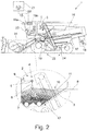
- the radar sensor 5 is located in the area of the bottom 12 of the crop tank 3 and is sending out radar rays 6 into the direction of the surface 11 of the crop C contained in the crop tank 3 as well.
- the radar sensor 5 is located within the crop C contained in the crop tank 3.
- the sensor control 9 locates the surface 11 of the crop C contained in the crop tank 3 based on the received radar rays 7.
- sensor control 9 evaluates a value for the time needed for the radar ray 6, 7 to be reflected, which represents the distance between the radar sensor 5 and the point of reflection as noted above. With the radar sensor 5 being located in the area of the bottom 12 of the crop tank 3, the highest distance value may be a value for the fill level of the crop tank 3.
- the sensor control 9 evaluates the portion of the sent radar rays 6, which is not being reflected back to the radar sensor 5.
- the idea behind this is the fact that depending on the fill level 8 of the crop C contained in the crop tank 3 a different portion of the sent radar rays 6 are completely passing through the crop C contained in the crop tank 3, not being reflected to the radar sensor 5. Accordingly, based on the portion of the sent radar rays 6, which is not being reflected to the radar sensor 5, a value for the fill level of the crop tank 3 may be determined.
- the sensor control 9 evaluates the dampening of the received radar rays 7 with respect to the sent radar rays 6, in order to obtain the respective fill level information.
- the obtained fill level information may vary. This at least in some cases makes it necessary to run a calibration process before reliable fill level information is available.
- the crop tank 3 of the crop tank system 2 is being filled manually by 100 %.
- the fill level sensor arrangement 4 runs a measurement, which measurement should show a fill level 8 of 100 % accordingly. If this is not the case, a correction value will be derived from the measured fill level and the actual fill level 8. All following measured fill levels will be corrected by this correction value.
- the agricultural machine 1 as such as being claimed, which agricultural machine 1, here and preferably, is a combine.
- the agricultural machine 1 serves for conducting an agricultural working process and is provided with a driver assistance system 13 as well as with a proposed crop tank system 2. All explanations given regarding the proposed crop tank system 2 are fully applicable to this second teaching.
- the driver assistance system 13 data-processes the obtained fill level information for the running agricultural working process. It is also possible that the obtained fill level information will be used for parallel agricultural working processes and/or subsequent agricultural working processes, as will be explained later.
- the agricultural machine 1 is a self-propelled harvesting machine, in particular a combine as noted above.
- the agricultural machine 1 comprises at least one working organ 14-18, wherein, here and preferably, the driver assistance system 13 serves for the control of at least one working organ 14-18.
- the agricultural machine 1 comprises a number of working organs 14-18, for example a front attachment 14, a threshing unit 15, a separating unit 16, a cleaning unit 17 and a distribution unit 18.
- Other working organs are a traction drive, a steering drive, or the like.
- the driver assistance system 13 data-processes the obtained fill level information by controlling at least one working organ 14-18 of the agricultural machine 1 based on the fill level information, which has been obtained in the running agricultural working process or a previous agricultural working process.
- the driver assistance system 13 following predefined operational strategies such as maximizing the crop output of the agricultural machine 1.
- the driver assistance system 13 evaluates the obtained fill rate and controls the traction drive as well as the threshing unit 15 in order to comply with the operational strategy. Accordingly, the obtained fill level information is an integral part of a respective control loop of the agricultural machine 1.
- Another example for data-processing the obtained fill level information may be the organization of tractor-pulled trailers, which serve to transport the harvested crop from the field.
- the agricultural machine 1 depending on the fill level information, may send a request to an organizational network in order to have a trailer arrive at the field such that the crop C contained in the crop tank 3 may be transferred to the respective trailer.
- the obtained fill level information is preferably used for mapping of a field, which means that the obtained field information, preferably the fill rate, is stored in a data base 20 such that this information may be retrieved whenever an agricultural working process is to be conducted on this respective field.
- the driver assistance system 13 data-processes the obtained fill level information by georeferencing the obtained fill level information. This means, that the driver assistance system 13 assigns each fill level information to the respective position information.
- the driver assistance system 13 comprises a positioning system, preferably a GPS-based positioning system.
- the georeferenced fill level information is being stored in memory 19a of the driver assistance system 13, which also is provided with a processing unit 19b to data-process the data contained in the memory 19a.
- the georeferenced fill level information is being transmitted to a data base 20 by the driver assistance system 13.
- the data base 20 is located on a data server 21, which is remote from the agricultural machine 1.
- the data server 21 may be a central server which administrates numerous data bases 20 representing the respective field information.
- One advantage of storing the obtained fill level information in a data base 20 is the availability of the obtained fill level information for all subsequent agricultural working processes. Further it may be possible to establish a complete history of the obtained information such that trends in changes of the fill level information, in particular of the fill rate, may be detected. Those trends may trigger certain measures to counteract the detected trend.
- driver assistance system 13 Another possibility for the driver assistance system 13 to data-process the obtained fill level information goes back on the agricultural machine 1 preferably comprising an adjustable chassis 22 with wheels 25 - 28, wherein the driver assistance system 13, based on the obtained fill level information, adjusts the chassis 22 or proposes to the user such adjustment via a man-machine-interface 23. With this it is possible to prevent the agricultural machine 1 from lowering due to an increase of weight, that goes along with the increase of fill level 8.
- the agricultural machine 1 comprises at least two above noted wheels with tires and that the agricultural machine 1 comprises an air pressure unit 24, which air pressure unit 24 may be controlled to change the air pressure of the tires assigned to the wheels, the driver assistance system 13, based on the obtained fill level information, preferably adjusts the air pressure of the tires or proposes to the user such adjustment via the above man-machine-interface 23.
- the adjustment of the air pressure of the tires may be done based on the above noted fill level information.
- the basic principle of using the obtained fill level information for conducting the agricultural working process is similar to the operation of the agricultural machine according to the second teaching.
- the subsequent working processes may be conducted by any agricultural machine 1, which may or may not be designed according to the second invention.
- all explanations given for the operation of the agricultural machine 1 according to the second teaching are fully applicable to the third teaching.
- An example for the proposed method is a combine conducting the harvesting process and at the same time obtaining the fill level information via the proposed fill level sensor arrangement 4.
- this fill level information is taken into account by the driver assistance system 13 for controlling the working organs 14-18.
- the obtained fill level information is being georeferenced and is either being stored in a local memory 19a or being transmitted to a data base 20, this fill level information may be used by subsequent agricultural working processes.
- the fill level information which is obtained within the running agricultural process, is the basis for the operation of the agricultural machine 1 or another agricultural machine within in a subsequent agricultural working process. With the use of the fill level information not only for the running agricultural working process, but possibly also for a subsequent agricultural working process, a double use of the fill level information is resulting, which as such leads to an increase in efficiency.
Applications Claiming Priority (1)
| Application Number | Priority Date | Filing Date | Title |
|---|---|---|---|
| DE102016100983 | 2016-01-21 |
Publications (1)
| Publication Number | Publication Date |
|---|---|
| EP3195720A1 true EP3195720A1 (fr) | 2017-07-26 |
Family
ID=57249677
Family Applications (1)
| Application Number | Title | Priority Date | Filing Date |
|---|---|---|---|
| EP16195715.4A Withdrawn EP3195720A1 (fr) | 2016-01-21 | 2016-10-26 | Système de réservoir de culture |
Country Status (2)
| Country | Link |
|---|---|
| US (1) | US20170208742A1 (fr) |
| EP (1) | EP3195720A1 (fr) |
Cited By (33)
| Publication number | Priority date | Publication date | Assignee | Title |
|---|---|---|---|---|
| EP3643159A1 (fr) * | 2018-10-26 | 2020-04-29 | Deere & Company | Système de commande de machine de récolte comportant un traitement du niveau de remplissage sur la base de données de rendement |
| US11079725B2 (en) | 2019-04-10 | 2021-08-03 | Deere & Company | Machine control using real-time model |
| US11234366B2 (en) | 2019-04-10 | 2022-02-01 | Deere & Company | Image selection for machine control |
| US11240961B2 (en) | 2018-10-26 | 2022-02-08 | Deere & Company | Controlling a harvesting machine based on a geo-spatial representation indicating where the harvesting machine is likely to reach capacity |
| US20220110251A1 (en) | 2020-10-09 | 2022-04-14 | Deere & Company | Crop moisture map generation and control system |
| US11467605B2 (en) | 2019-04-10 | 2022-10-11 | Deere & Company | Zonal machine control |
| US11474523B2 (en) | 2020-10-09 | 2022-10-18 | Deere & Company | Machine control using a predictive speed map |
| US11477940B2 (en) | 2020-03-26 | 2022-10-25 | Deere & Company | Mobile work machine control based on zone parameter modification |
| US11592822B2 (en) | 2020-10-09 | 2023-02-28 | Deere & Company | Machine control using a predictive map |
| US11589509B2 (en) | 2018-10-26 | 2023-02-28 | Deere & Company | Predictive machine characteristic map generation and control system |
| US11635765B2 (en) | 2020-10-09 | 2023-04-25 | Deere & Company | Crop state map generation and control system |
| US11641800B2 (en) | 2020-02-06 | 2023-05-09 | Deere & Company | Agricultural harvesting machine with pre-emergence weed detection and mitigation system |
| US11650587B2 (en) | 2020-10-09 | 2023-05-16 | Deere & Company | Predictive power map generation and control system |
| US11653588B2 (en) | 2018-10-26 | 2023-05-23 | Deere & Company | Yield map generation and control system |
| US11675354B2 (en) | 2020-10-09 | 2023-06-13 | Deere & Company | Machine control using a predictive map |
| US11672203B2 (en) | 2018-10-26 | 2023-06-13 | Deere & Company | Predictive map generation and control |
| US11711995B2 (en) | 2020-10-09 | 2023-08-01 | Deere & Company | Machine control using a predictive map |
| US11727680B2 (en) | 2020-10-09 | 2023-08-15 | Deere & Company | Predictive map generation based on seeding characteristics and control |
| US11778945B2 (en) | 2019-04-10 | 2023-10-10 | Deere & Company | Machine control using real-time model |
| US11825768B2 (en) | 2020-10-09 | 2023-11-28 | Deere & Company | Machine control using a predictive map |
| US11844311B2 (en) | 2020-10-09 | 2023-12-19 | Deere & Company | Machine control using a predictive map |
| US11845449B2 (en) | 2020-10-09 | 2023-12-19 | Deere & Company | Map generation and control system |
| US11849672B2 (en) | 2020-10-09 | 2023-12-26 | Deere & Company | Machine control using a predictive map |
| US11849671B2 (en) | 2020-10-09 | 2023-12-26 | Deere & Company | Crop state map generation and control system |
| US11864483B2 (en) | 2020-10-09 | 2024-01-09 | Deere & Company | Predictive map generation and control system |
| US11874669B2 (en) | 2020-10-09 | 2024-01-16 | Deere & Company | Map generation and control system |
| US11889788B2 (en) | 2020-10-09 | 2024-02-06 | Deere & Company | Predictive biomass map generation and control |
| US11889787B2 (en) | 2020-10-09 | 2024-02-06 | Deere & Company | Predictive speed map generation and control system |
| US11895948B2 (en) | 2020-10-09 | 2024-02-13 | Deere & Company | Predictive map generation and control based on soil properties |
| US11927459B2 (en) | 2020-10-09 | 2024-03-12 | Deere & Company | Machine control using a predictive map |
| US11946747B2 (en) | 2020-10-09 | 2024-04-02 | Deere & Company | Crop constituent map generation and control system |
| US11957072B2 (en) | 2020-02-06 | 2024-04-16 | Deere & Company | Pre-emergence weed detection and mitigation system |
| US11983009B2 (en) | 2020-10-09 | 2024-05-14 | Deere & Company | Map generation and control system |
Families Citing this family (10)
| Publication number | Priority date | Publication date | Assignee | Title |
|---|---|---|---|---|
| US10351364B2 (en) * | 2016-08-05 | 2019-07-16 | Deere & Company | Automatic vehicle and conveyor positioning |
| US10368488B2 (en) * | 2017-09-18 | 2019-08-06 | Cnh Industrial America Llc | System and method for sensing harvested crop levels within an agricultural harvester |
| EP3459339B1 (fr) * | 2017-09-21 | 2021-06-23 | CNH Industrial Belgium NV | Mesure de niveau de bac continue réglable par l'opérateur |
| KR20200085276A (ko) * | 2017-11-24 | 2020-07-14 | 가부시끼 가이샤 구보다 | 수확기, 한계 주행 거리 산출 프로그램, 한계 주행 거리 산출 프로그램을 기록한 기록 매체, 한계 주행 거리 산출 방법, 농작업차, 선회 제어 프로그램, 선회 제어 프로그램을 기록한 기록 매체, 선회 제어 방법, 콤바인 제어 시스템, 콤바인 제어 프로그램, 콤바인 제어 프로그램을 기록한 기록 매체, 콤바인 제어 방법 |
| US10701861B2 (en) * | 2018-07-19 | 2020-07-07 | Cnh Industrial America Llc | Modular sensor array for bulk material detection |
| DE102019204671A1 (de) * | 2019-04-02 | 2020-10-08 | Vega Grieshaber Kg | Radarmodul mit Doppelfinne |
| CN112997678A (zh) * | 2021-03-01 | 2021-06-22 | 潍柴雷沃重工股份有限公司 | 一种收获机自动卸粮控制系统、方法和收获机 |
| US11765993B2 (en) * | 2021-05-17 | 2023-09-26 | Deere & Company | Control system detecting fill level on receiving vehicle(s) |
| US11930738B2 (en) | 2021-06-28 | 2024-03-19 | Deere & Company | Closed loop control of filling mechanisms |
| US20230071349A1 (en) * | 2021-09-07 | 2023-03-09 | Cnh Industrial America Llc | Target for grain tank level sensor integrated into the grain tank |
Citations (7)
| Publication number | Priority date | Publication date | Assignee | Title |
|---|---|---|---|---|
| US6144295A (en) * | 1998-12-11 | 2000-11-07 | Case Corporation | Automatic central tire inflation system |
| US20040031335A1 (en) * | 2000-02-17 | 2004-02-19 | Fromme Guy A. | Bulk materials management apparatus and method |
| DE10345612A1 (de) * | 2003-09-29 | 2005-06-09 | Claas Selbstfahrende Erntemaschinen Gmbh | Wägesystem an einer landwirtschaftlichen Maschine |
| US20060240884A1 (en) * | 2005-04-20 | 2006-10-26 | Torsten Klimmer | Ultrasonic sensor on a grain tank cover |
| US20120253611A1 (en) * | 2011-03-31 | 2012-10-04 | Ag Leader Technology | Combine bin level monitoring system |
| DE202013102514U1 (de) * | 2013-06-11 | 2013-06-17 | Vega Grieshaber Kg | Füllstandmessgerät zur Feuchtigkeitsbestimmung |
| US20160000008A1 (en) * | 2011-03-11 | 2016-01-07 | Intelligent Agricultural Solutions, Llc | Harvesting machine capable of automatic adjustment |
-
2016
- 2016-10-26 EP EP16195715.4A patent/EP3195720A1/fr not_active Withdrawn
-
2017
- 2017-01-20 US US15/411,219 patent/US20170208742A1/en not_active Abandoned
Patent Citations (7)
| Publication number | Priority date | Publication date | Assignee | Title |
|---|---|---|---|---|
| US6144295A (en) * | 1998-12-11 | 2000-11-07 | Case Corporation | Automatic central tire inflation system |
| US20040031335A1 (en) * | 2000-02-17 | 2004-02-19 | Fromme Guy A. | Bulk materials management apparatus and method |
| DE10345612A1 (de) * | 2003-09-29 | 2005-06-09 | Claas Selbstfahrende Erntemaschinen Gmbh | Wägesystem an einer landwirtschaftlichen Maschine |
| US20060240884A1 (en) * | 2005-04-20 | 2006-10-26 | Torsten Klimmer | Ultrasonic sensor on a grain tank cover |
| US20160000008A1 (en) * | 2011-03-11 | 2016-01-07 | Intelligent Agricultural Solutions, Llc | Harvesting machine capable of automatic adjustment |
| US20120253611A1 (en) * | 2011-03-31 | 2012-10-04 | Ag Leader Technology | Combine bin level monitoring system |
| DE202013102514U1 (de) * | 2013-06-11 | 2013-06-17 | Vega Grieshaber Kg | Füllstandmessgerät zur Feuchtigkeitsbestimmung |
Cited By (37)
| Publication number | Priority date | Publication date | Assignee | Title |
|---|---|---|---|---|
| US11653588B2 (en) | 2018-10-26 | 2023-05-23 | Deere & Company | Yield map generation and control system |
| US11672203B2 (en) | 2018-10-26 | 2023-06-13 | Deere & Company | Predictive map generation and control |
| US11178818B2 (en) | 2018-10-26 | 2021-11-23 | Deere & Company | Harvesting machine control system with fill level processing based on yield data |
| EP3643159A1 (fr) * | 2018-10-26 | 2020-04-29 | Deere & Company | Système de commande de machine de récolte comportant un traitement du niveau de remplissage sur la base de données de rendement |
| US11240961B2 (en) | 2018-10-26 | 2022-02-08 | Deere & Company | Controlling a harvesting machine based on a geo-spatial representation indicating where the harvesting machine is likely to reach capacity |
| US11589509B2 (en) | 2018-10-26 | 2023-02-28 | Deere & Company | Predictive machine characteristic map generation and control system |
| US11467605B2 (en) | 2019-04-10 | 2022-10-11 | Deere & Company | Zonal machine control |
| US11829112B2 (en) | 2019-04-10 | 2023-11-28 | Deere & Company | Machine control using real-time model |
| US11778945B2 (en) | 2019-04-10 | 2023-10-10 | Deere & Company | Machine control using real-time model |
| US11234366B2 (en) | 2019-04-10 | 2022-02-01 | Deere & Company | Image selection for machine control |
| US11650553B2 (en) | 2019-04-10 | 2023-05-16 | Deere & Company | Machine control using real-time model |
| US11079725B2 (en) | 2019-04-10 | 2021-08-03 | Deere & Company | Machine control using real-time model |
| US11957072B2 (en) | 2020-02-06 | 2024-04-16 | Deere & Company | Pre-emergence weed detection and mitigation system |
| US11641800B2 (en) | 2020-02-06 | 2023-05-09 | Deere & Company | Agricultural harvesting machine with pre-emergence weed detection and mitigation system |
| US11477940B2 (en) | 2020-03-26 | 2022-10-25 | Deere & Company | Mobile work machine control based on zone parameter modification |
| US11711995B2 (en) | 2020-10-09 | 2023-08-01 | Deere & Company | Machine control using a predictive map |
| US11849671B2 (en) | 2020-10-09 | 2023-12-26 | Deere & Company | Crop state map generation and control system |
| US11650587B2 (en) | 2020-10-09 | 2023-05-16 | Deere & Company | Predictive power map generation and control system |
| US11635765B2 (en) | 2020-10-09 | 2023-04-25 | Deere & Company | Crop state map generation and control system |
| US11727680B2 (en) | 2020-10-09 | 2023-08-15 | Deere & Company | Predictive map generation based on seeding characteristics and control |
| US11592822B2 (en) | 2020-10-09 | 2023-02-28 | Deere & Company | Machine control using a predictive map |
| US11474523B2 (en) | 2020-10-09 | 2022-10-18 | Deere & Company | Machine control using a predictive speed map |
| US11825768B2 (en) | 2020-10-09 | 2023-11-28 | Deere & Company | Machine control using a predictive map |
| US11844311B2 (en) | 2020-10-09 | 2023-12-19 | Deere & Company | Machine control using a predictive map |
| US11845449B2 (en) | 2020-10-09 | 2023-12-19 | Deere & Company | Map generation and control system |
| US11849672B2 (en) | 2020-10-09 | 2023-12-26 | Deere & Company | Machine control using a predictive map |
| US11675354B2 (en) | 2020-10-09 | 2023-06-13 | Deere & Company | Machine control using a predictive map |
| US11864483B2 (en) | 2020-10-09 | 2024-01-09 | Deere & Company | Predictive map generation and control system |
| US11874669B2 (en) | 2020-10-09 | 2024-01-16 | Deere & Company | Map generation and control system |
| US11871697B2 (en) | 2020-10-09 | 2024-01-16 | Deere & Company | Crop moisture map generation and control system |
| US11889788B2 (en) | 2020-10-09 | 2024-02-06 | Deere & Company | Predictive biomass map generation and control |
| US11889787B2 (en) | 2020-10-09 | 2024-02-06 | Deere & Company | Predictive speed map generation and control system |
| US11895948B2 (en) | 2020-10-09 | 2024-02-13 | Deere & Company | Predictive map generation and control based on soil properties |
| US11927459B2 (en) | 2020-10-09 | 2024-03-12 | Deere & Company | Machine control using a predictive map |
| US11946747B2 (en) | 2020-10-09 | 2024-04-02 | Deere & Company | Crop constituent map generation and control system |
| US20220110251A1 (en) | 2020-10-09 | 2022-04-14 | Deere & Company | Crop moisture map generation and control system |
| US11983009B2 (en) | 2020-10-09 | 2024-05-14 | Deere & Company | Map generation and control system |
Also Published As
| Publication number | Publication date |
|---|---|
| US20170208742A1 (en) | 2017-07-27 |
Similar Documents
| Publication | Publication Date | Title |
|---|---|---|
| EP3195720A1 (fr) | Système de réservoir de culture | |
| US20200126166A1 (en) | Agricultural implement and implement operator monitoring apparatus, systems, and methods | |
| US11212962B2 (en) | Field condition determination | |
| EP3195719B1 (fr) | Machine agricole | |
| US9832928B2 (en) | Crop sensing | |
| CN110582794A (zh) | 联合收割机、田地农业经营地图生成方法、田地农业经营地图生成程序及记录有田地农业经营地图生成程序的记录介质 | |
| US10178828B2 (en) | Per plant crop sensing resolution | |
| US9668420B2 (en) | Crop sensing display | |
| CN108605496B (zh) | 农作业机、农作业管理方法以及记录了其程序的记录介质 | |
| US7480564B2 (en) | System for determining the relative position of a second farm vehicle in relation to a first farm vehicle | |
| EP2020168A1 (fr) | Système de commande pour véhicules de travail agricole | |
| US10278329B2 (en) | Grain management system and combine | |
| US11116132B2 (en) | Self-propelled harvesting machine with sensors for sensing crop density | |
| JP6494344B2 (ja) | コンバイン | |
| JP2015084749A (ja) | 圃場認識システム | |
| US11874367B2 (en) | Method for ascertaining a plant height of field crops | |
| US11533901B2 (en) | Traveling vehicle | |
| KR20170072495A (ko) | 농업용 작업차량의 운전제어 장치 및 운전제어 방법 | |
| US20220015280A1 (en) | Apparatus for locating an agricultural machine on the basis of sensor data and image segmentation | |
| JP2020162490A (ja) | 散布支援装置及び散布支援システム | |
| JP2016173621A (ja) | 穀粒管理システム |
Legal Events
| Date | Code | Title | Description |
|---|---|---|---|
| PUAI | Public reference made under article 153(3) epc to a published international application that has entered the european phase |
Free format text: ORIGINAL CODE: 0009012 |
|
| AK | Designated contracting states |
Kind code of ref document: A1 Designated state(s): AL AT BE BG CH CY CZ DE DK EE ES FI FR GB GR HR HU IE IS IT LI LT LU LV MC MK MT NL NO PL PT RO RS SE SI SK SM TR |
|
| AX | Request for extension of the european patent |
Extension state: BA ME |
|
| RAP1 | Party data changed (applicant data changed or rights of an application transferred) |
Owner name: CLAAS E-SYSTEMS KGAA MBH & CO KG |
|
| STAA | Information on the status of an ep patent application or granted ep patent |
Free format text: STATUS: THE APPLICATION HAS BEEN WITHDRAWN |
|
| 18W | Application withdrawn |
Effective date: 20180117 |