EP3194961B1 - Résonateur acoustique à onde de volume en film mince avec réhaussement de signal - Google Patents
Résonateur acoustique à onde de volume en film mince avec réhaussement de signal Download PDFInfo
- Publication number
- EP3194961B1 EP3194961B1 EP15842191.7A EP15842191A EP3194961B1 EP 3194961 B1 EP3194961 B1 EP 3194961B1 EP 15842191 A EP15842191 A EP 15842191A EP 3194961 B1 EP3194961 B1 EP 3194961B1
- Authority
- EP
- European Patent Office
- Prior art keywords
- recognition component
- analyte
- tfbar
- linked
- amplification element
- Prior art date
- Legal status (The legal status is an assumption and is not a legal conclusion. Google has not performed a legal analysis and makes no representation as to the accuracy of the status listed.)
- Active
Links
- 239000010409 thin film Substances 0.000 title claims description 27
- 238000003199 nucleic acid amplification method Methods 0.000 claims description 116
- 230000003321 amplification Effects 0.000 claims description 115
- 239000012491 analyte Substances 0.000 claims description 97
- 230000027455 binding Effects 0.000 claims description 84
- 238000000034 method Methods 0.000 claims description 32
- 239000000758 substrate Substances 0.000 claims description 30
- 102000004190 Enzymes Human genes 0.000 claims description 29
- 108090000790 Enzymes Proteins 0.000 claims description 29
- 230000008859 change Effects 0.000 claims description 18
- 230000010363 phase shift Effects 0.000 claims description 15
- 238000005259 measurement Methods 0.000 claims description 9
- 239000002244 precipitate Substances 0.000 claims description 8
- 238000003780 insertion Methods 0.000 claims description 7
- 230000037431 insertion Effects 0.000 claims description 7
- 239000002243 precursor Substances 0.000 claims description 7
- 230000008021 deposition Effects 0.000 claims description 5
- 239000012530 fluid Substances 0.000 claims description 4
- 230000008878 coupling Effects 0.000 claims description 2
- 238000010168 coupling process Methods 0.000 claims description 2
- 238000005859 coupling reaction Methods 0.000 claims description 2
- 239000000463 material Substances 0.000 description 31
- 229940088598 enzyme Drugs 0.000 description 28
- 230000035945 sensitivity Effects 0.000 description 16
- 238000003556 assay Methods 0.000 description 14
- 238000011068 loading method Methods 0.000 description 11
- 238000012360 testing method Methods 0.000 description 11
- QEIFSLUFHRCVQL-UHFFFAOYSA-N (5-bromo-4-chloro-1h-indol-3-yl) hydrogen phosphate;(4-methylphenyl)azanium Chemical compound CC1=CC=C(N)C=C1.C1=C(Br)C(Cl)=C2C(OP(O)(=O)O)=CNC2=C1 QEIFSLUFHRCVQL-UHFFFAOYSA-N 0.000 description 10
- 230000004044 response Effects 0.000 description 10
- 102000002260 Alkaline Phosphatase Human genes 0.000 description 9
- 108020004774 Alkaline Phosphatase Proteins 0.000 description 9
- 102000004889 Interleukin-6 Human genes 0.000 description 9
- 108090001005 Interleukin-6 Proteins 0.000 description 9
- 230000001404 mediated effect Effects 0.000 description 9
- 229940100601 interleukin-6 Drugs 0.000 description 8
- 239000000203 mixture Substances 0.000 description 8
- 239000000047 product Substances 0.000 description 8
- JKMHFZQWWAIEOD-UHFFFAOYSA-N 2-[4-(2-hydroxyethyl)piperazin-1-yl]ethanesulfonic acid Chemical compound OCC[NH+]1CCN(CCS([O-])(=O)=O)CC1 JKMHFZQWWAIEOD-UHFFFAOYSA-N 0.000 description 7
- 108010001336 Horseradish Peroxidase Proteins 0.000 description 6
- PXHVJJICTQNCMI-UHFFFAOYSA-N Nickel Chemical compound [Ni] PXHVJJICTQNCMI-UHFFFAOYSA-N 0.000 description 6
- 238000001514 detection method Methods 0.000 description 6
- 238000003380 quartz crystal microbalance Methods 0.000 description 6
- 238000005406 washing Methods 0.000 description 6
- 241000283707 Capra Species 0.000 description 5
- 230000008901 benefit Effects 0.000 description 5
- 238000000151 deposition Methods 0.000 description 5
- YBJHBAHKTGYVGT-ZKWXMUAHSA-N (+)-Biotin Chemical compound N1C(=O)N[C@@H]2[C@H](CCCCC(=O)O)SC[C@@H]21 YBJHBAHKTGYVGT-ZKWXMUAHSA-N 0.000 description 4
- 241000251468 Actinopterygii Species 0.000 description 4
- 239000004593 Epoxy Substances 0.000 description 4
- 108010010803 Gelatin Proteins 0.000 description 4
- BLRPTPMANUNPDV-UHFFFAOYSA-N Silane Chemical compound [SiH4] BLRPTPMANUNPDV-UHFFFAOYSA-N 0.000 description 4
- 108010090804 Streptavidin Proteins 0.000 description 4
- 238000006243 chemical reaction Methods 0.000 description 4
- 239000003153 chemical reaction reagent Substances 0.000 description 4
- 230000000295 complement effect Effects 0.000 description 4
- 238000010586 diagram Methods 0.000 description 4
- 238000005516 engineering process Methods 0.000 description 4
- 230000006870 function Effects 0.000 description 4
- 229920000159 gelatin Polymers 0.000 description 4
- 239000008273 gelatin Substances 0.000 description 4
- 235000019322 gelatine Nutrition 0.000 description 4
- 235000011852 gelatine desserts Nutrition 0.000 description 4
- 230000010355 oscillation Effects 0.000 description 4
- 102000004196 processed proteins & peptides Human genes 0.000 description 4
- 108090000765 processed proteins & peptides Proteins 0.000 description 4
- 229910000077 silane Inorganic materials 0.000 description 4
- 108010070675 Glutathione transferase Proteins 0.000 description 3
- 239000007995 HEPES buffer Substances 0.000 description 3
- 102100029100 Hematopoietic prostaglandin D synthase Human genes 0.000 description 3
- 108091034117 Oligonucleotide Proteins 0.000 description 3
- XLOMVQKBTHCTTD-UHFFFAOYSA-N Zinc monoxide Chemical compound [Zn]=O XLOMVQKBTHCTTD-UHFFFAOYSA-N 0.000 description 3
- 239000003599 detergent Substances 0.000 description 3
- 238000003018 immunoassay Methods 0.000 description 3
- 229910052759 nickel Inorganic materials 0.000 description 3
- 102000039446 nucleic acids Human genes 0.000 description 3
- 108020004707 nucleic acids Proteins 0.000 description 3
- 150000007523 nucleic acids Chemical class 0.000 description 3
- 230000001376 precipitating effect Effects 0.000 description 3
- NGSWKAQJJWESNS-UHFFFAOYSA-N 4-coumaric acid Chemical compound OC(=O)C=CC1=CC=C(O)C=C1 NGSWKAQJJWESNS-UHFFFAOYSA-N 0.000 description 2
- 108020004414 DNA Proteins 0.000 description 2
- ZHNUHDYFZUAESO-UHFFFAOYSA-N Formamide Chemical compound NC=O ZHNUHDYFZUAESO-UHFFFAOYSA-N 0.000 description 2
- MHAJPDPJQMAIIY-UHFFFAOYSA-N Hydrogen peroxide Chemical compound OO MHAJPDPJQMAIIY-UHFFFAOYSA-N 0.000 description 2
- 101710175625 Maltose/maltodextrin-binding periplasmic protein Proteins 0.000 description 2
- 102000003992 Peroxidases Human genes 0.000 description 2
- 102000004160 Phosphoric Monoester Hydrolases Human genes 0.000 description 2
- 108090000608 Phosphoric Monoester Hydrolases Proteins 0.000 description 2
- PXIPVTKHYLBLMZ-UHFFFAOYSA-N Sodium azide Chemical compound [Na+].[N-]=[N+]=[N-] PXIPVTKHYLBLMZ-UHFFFAOYSA-N 0.000 description 2
- 238000004458 analytical method Methods 0.000 description 2
- -1 antibodies Proteins 0.000 description 2
- 239000000427 antigen Substances 0.000 description 2
- 102000036639 antigens Human genes 0.000 description 2
- 108091007433 antigens Proteins 0.000 description 2
- 229960002685 biotin Drugs 0.000 description 2
- 235000020958 biotin Nutrition 0.000 description 2
- 239000011616 biotin Substances 0.000 description 2
- 239000000872 buffer Substances 0.000 description 2
- 239000007975 buffered saline Substances 0.000 description 2
- 150000001720 carbohydrates Chemical class 0.000 description 2
- 235000014633 carbohydrates Nutrition 0.000 description 2
- 239000002738 chelating agent Substances 0.000 description 2
- 102000021178 chitin binding proteins Human genes 0.000 description 2
- 108091011157 chitin binding proteins Proteins 0.000 description 2
- 229910017052 cobalt Inorganic materials 0.000 description 2
- 239000010941 cobalt Substances 0.000 description 2
- GUTLYIVDDKVIGB-UHFFFAOYSA-N cobalt atom Chemical compound [Co] GUTLYIVDDKVIGB-UHFFFAOYSA-N 0.000 description 2
- 238000011161 development Methods 0.000 description 2
- 235000014113 dietary fatty acids Nutrition 0.000 description 2
- LOKCTEFSRHRXRJ-UHFFFAOYSA-I dipotassium trisodium dihydrogen phosphate hydrogen phosphate dichloride Chemical compound P(=O)(O)(O)[O-].[K+].P(=O)(O)([O-])[O-].[Na+].[Na+].[Cl-].[K+].[Cl-].[Na+] LOKCTEFSRHRXRJ-UHFFFAOYSA-I 0.000 description 2
- 229930195729 fatty acid Natural products 0.000 description 2
- 239000000194 fatty acid Substances 0.000 description 2
- RWSXRVCMGQZWBV-WDSKDSINSA-N glutathione Chemical compound OC(=O)[C@@H](N)CCC(=O)N[C@@H](CS)C(=O)NCC(O)=O RWSXRVCMGQZWBV-WDSKDSINSA-N 0.000 description 2
- PCHJSUWPFVWCPO-UHFFFAOYSA-N gold Chemical compound [Au] PCHJSUWPFVWCPO-UHFFFAOYSA-N 0.000 description 2
- 229910052737 gold Inorganic materials 0.000 description 2
- 239000010931 gold Substances 0.000 description 2
- HFGPZNIAWCZYJU-UHFFFAOYSA-N lead zirconate titanate Chemical compound [O-2].[O-2].[O-2].[O-2].[O-2].[Ti+4].[Zr+4].[Pb+2] HFGPZNIAWCZYJU-UHFFFAOYSA-N 0.000 description 2
- 239000011159 matrix material Substances 0.000 description 2
- 229910052751 metal Inorganic materials 0.000 description 2
- 239000002184 metal Substances 0.000 description 2
- 239000002953 phosphate buffered saline Substances 0.000 description 2
- 239000003505 polymerization initiator Substances 0.000 description 2
- 230000008569 process Effects 0.000 description 2
- 102000004169 proteins and genes Human genes 0.000 description 2
- 108090000623 proteins and genes Proteins 0.000 description 2
- 239000010453 quartz Substances 0.000 description 2
- 229920005989 resin Polymers 0.000 description 2
- 239000011347 resin Substances 0.000 description 2
- 210000002966 serum Anatomy 0.000 description 2
- VYPSYNLAJGMNEJ-UHFFFAOYSA-N silicon dioxide Inorganic materials O=[Si]=O VYPSYNLAJGMNEJ-UHFFFAOYSA-N 0.000 description 2
- 239000000126 substance Substances 0.000 description 2
- 125000003396 thiol group Chemical group [H]S* 0.000 description 2
- 239000011534 wash buffer Substances 0.000 description 2
- BTLHODXEDLCLAD-VKHMYHEASA-N (2s)-2-(carboxymethylamino)butanedioic acid Chemical compound OC(=O)CN[C@H](C(O)=O)CC(O)=O BTLHODXEDLCLAD-VKHMYHEASA-N 0.000 description 1
- QRXMUCSWCMTJGU-UHFFFAOYSA-L (5-bromo-4-chloro-1h-indol-3-yl) phosphate Chemical compound C1=C(Br)C(Cl)=C2C(OP([O-])(=O)[O-])=CNC2=C1 QRXMUCSWCMTJGU-UHFFFAOYSA-L 0.000 description 1
- JYEUMXHLPRZUAT-UHFFFAOYSA-N 1,2,3-triazine Chemical compound C1=CN=NN=C1 JYEUMXHLPRZUAT-UHFFFAOYSA-N 0.000 description 1
- OWEGMIWEEQEYGQ-UHFFFAOYSA-N 100676-05-9 Natural products OC1C(O)C(O)C(CO)OC1OCC1C(O)C(O)C(O)C(OC2C(OC(O)C(O)C2O)CO)O1 OWEGMIWEEQEYGQ-UHFFFAOYSA-N 0.000 description 1
- VEPOHXYIFQMVHW-XOZOLZJESA-N 2,3-dihydroxybutanedioic acid (2S,3S)-3,4-dimethyl-2-phenylmorpholine Chemical compound OC(C(O)C(O)=O)C(O)=O.C[C@H]1[C@@H](OCCN1C)c1ccccc1 VEPOHXYIFQMVHW-XOZOLZJESA-N 0.000 description 1
- JRBJSXQPQWSCCF-UHFFFAOYSA-N 3,3'-Dimethoxybenzidine Chemical compound C1=C(N)C(OC)=CC(C=2C=C(OC)C(N)=CC=2)=C1 JRBJSXQPQWSCCF-UHFFFAOYSA-N 0.000 description 1
- QFVHZQCOUORWEI-UHFFFAOYSA-N 4-[(4-anilino-5-sulfonaphthalen-1-yl)diazenyl]-5-hydroxynaphthalene-2,7-disulfonic acid Chemical compound C=12C(O)=CC(S(O)(=O)=O)=CC2=CC(S(O)(=O)=O)=CC=1N=NC(C1=CC=CC(=C11)S(O)(=O)=O)=CC=C1NC1=CC=CC=C1 QFVHZQCOUORWEI-UHFFFAOYSA-N 0.000 description 1
- YBJHBAHKTGYVGT-ZXFLCMHBSA-N 5-[(3ar,4r,6as)-2-oxo-1,3,3a,4,6,6a-hexahydrothieno[3,4-d]imidazol-4-yl]pentanoic acid Chemical compound N1C(=O)N[C@H]2[C@@H](CCCCC(=O)O)SC[C@H]21 YBJHBAHKTGYVGT-ZXFLCMHBSA-N 0.000 description 1
- WSMQKESQZFQMFW-UHFFFAOYSA-N 5-methyl-pyrazole-3-carboxylic acid Chemical compound CC1=CC(C(O)=O)=NN1 WSMQKESQZFQMFW-UHFFFAOYSA-N 0.000 description 1
- OXEUETBFKVCRNP-UHFFFAOYSA-N 9-ethyl-3-carbazolamine Chemical compound NC1=CC=C2N(CC)C3=CC=CC=C3C2=C1 OXEUETBFKVCRNP-UHFFFAOYSA-N 0.000 description 1
- 108091023020 Aldehyde Oxidase Proteins 0.000 description 1
- PIGFYZPCRLYGLF-UHFFFAOYSA-N Aluminum nitride Chemical compound [Al]#N PIGFYZPCRLYGLF-UHFFFAOYSA-N 0.000 description 1
- 229920000856 Amylose Polymers 0.000 description 1
- 108090001008 Avidin Proteins 0.000 description 1
- 241000894006 Bacteria Species 0.000 description 1
- 102100026189 Beta-galactosidase Human genes 0.000 description 1
- 241000283690 Bos taurus Species 0.000 description 1
- 229920002101 Chitin Polymers 0.000 description 1
- RYGMFSIKBFXOCR-UHFFFAOYSA-N Copper Chemical compound [Cu] RYGMFSIKBFXOCR-UHFFFAOYSA-N 0.000 description 1
- 239000004971 Cross linker Substances 0.000 description 1
- 230000004568 DNA-binding Effects 0.000 description 1
- 241000233866 Fungi Species 0.000 description 1
- 241000287828 Gallus gallus Species 0.000 description 1
- WQZGKKKJIJFFOK-GASJEMHNSA-N Glucose Natural products OC[C@H]1OC(O)[C@H](O)[C@@H](O)[C@@H]1O WQZGKKKJIJFFOK-GASJEMHNSA-N 0.000 description 1
- 108010015776 Glucose oxidase Proteins 0.000 description 1
- 239000004366 Glucose oxidase Substances 0.000 description 1
- 108010024636 Glutathione Proteins 0.000 description 1
- HVLSXIKZNLPZJJ-TXZCQADKSA-N HA peptide Chemical compound C([C@@H](C(=O)N[C@@H](CC(O)=O)C(=O)N[C@@H](C(C)C)C(=O)N1[C@@H](CCC1)C(=O)N[C@@H](CC(O)=O)C(=O)N[C@@H](CC=1C=CC(O)=CC=1)C(=O)N[C@@H](C)C(O)=O)NC(=O)[C@H]1N(CCC1)C(=O)[C@@H](N)CC=1C=CC(O)=CC=1)C1=CC=C(O)C=C1 HVLSXIKZNLPZJJ-TXZCQADKSA-N 0.000 description 1
- HTTJABKRGRZYRN-UHFFFAOYSA-N Heparin Chemical compound OC1C(NC(=O)C)C(O)OC(COS(O)(=O)=O)C1OC1C(OS(O)(=O)=O)C(O)C(OC2C(C(OS(O)(=O)=O)C(OC3C(C(O)C(O)C(O3)C(O)=O)OS(O)(=O)=O)C(CO)O2)NS(O)(=O)=O)C(C(O)=O)O1 HTTJABKRGRZYRN-UHFFFAOYSA-N 0.000 description 1
- 101001076408 Homo sapiens Interleukin-6 Proteins 0.000 description 1
- 102000004856 Lectins Human genes 0.000 description 1
- 108090001090 Lectins Proteins 0.000 description 1
- 229910003327 LiNbO3 Inorganic materials 0.000 description 1
- 229910012463 LiTaO3 Inorganic materials 0.000 description 1
- GUBGYTABKSRVRQ-PICCSMPSSA-N Maltose Natural products O[C@@H]1[C@@H](O)[C@H](O)[C@@H](CO)O[C@@H]1O[C@@H]1[C@@H](CO)OC(O)[C@H](O)[C@H]1O GUBGYTABKSRVRQ-PICCSMPSSA-N 0.000 description 1
- ZOKXTWBITQBERF-UHFFFAOYSA-N Molybdenum Chemical compound [Mo] ZOKXTWBITQBERF-UHFFFAOYSA-N 0.000 description 1
- 102000003896 Myeloperoxidases Human genes 0.000 description 1
- 108090000235 Myeloperoxidases Proteins 0.000 description 1
- 241000283973 Oryctolagus cuniculus Species 0.000 description 1
- 102000004316 Oxidoreductases Human genes 0.000 description 1
- 108090000854 Oxidoreductases Proteins 0.000 description 1
- 108700020962 Peroxidase Proteins 0.000 description 1
- PCNDJXKNXGMECE-UHFFFAOYSA-N Phenazine Natural products C1=CC=CC2=NC3=CC=CC=C3N=C21 PCNDJXKNXGMECE-UHFFFAOYSA-N 0.000 description 1
- 108010039918 Polylysine Proteins 0.000 description 1
- 102000001253 Protein Kinase Human genes 0.000 description 1
- XUIMIQQOPSSXEZ-UHFFFAOYSA-N Silicon Chemical compound [Si] XUIMIQQOPSSXEZ-UHFFFAOYSA-N 0.000 description 1
- RTAQQCXQSZGOHL-UHFFFAOYSA-N Titanium Chemical compound [Ti] RTAQQCXQSZGOHL-UHFFFAOYSA-N 0.000 description 1
- 241000700605 Viruses Species 0.000 description 1
- 108010093894 Xanthine oxidase Proteins 0.000 description 1
- 102100033220 Xanthine oxidase Human genes 0.000 description 1
- 238000013019 agitation Methods 0.000 description 1
- 229940061720 alpha hydroxy acid Drugs 0.000 description 1
- 150000001280 alpha hydroxy acids Chemical class 0.000 description 1
- WQZGKKKJIJFFOK-PHYPRBDBSA-N alpha-D-galactose Chemical compound OC[C@H]1O[C@H](O)[C@H](O)[C@@H](O)[C@H]1O WQZGKKKJIJFFOK-PHYPRBDBSA-N 0.000 description 1
- 229910052782 aluminium Inorganic materials 0.000 description 1
- XAGFODPZIPBFFR-UHFFFAOYSA-N aluminium Chemical compound [Al] XAGFODPZIPBFFR-UHFFFAOYSA-N 0.000 description 1
- 150000001413 amino acids Chemical class 0.000 description 1
- 238000013459 approach Methods 0.000 description 1
- PGWTYMLATMNCCZ-UHFFFAOYSA-M azure A Chemical compound [Cl-].C1=CC(N)=CC2=[S+]C3=CC(N(C)C)=CC=C3N=C21 PGWTYMLATMNCCZ-UHFFFAOYSA-M 0.000 description 1
- WQZGKKKJIJFFOK-VFUOTHLCSA-N beta-D-glucose Chemical compound OC[C@H]1O[C@@H](O)[C@H](O)[C@@H](O)[C@@H]1O WQZGKKKJIJFFOK-VFUOTHLCSA-N 0.000 description 1
- 108010005774 beta-Galactosidase Proteins 0.000 description 1
- 210000004369 blood Anatomy 0.000 description 1
- 239000008280 blood Substances 0.000 description 1
- ZADPBFCGQRWHPN-UHFFFAOYSA-N boronic acid Chemical compound OBO ZADPBFCGQRWHPN-UHFFFAOYSA-N 0.000 description 1
- 150000001716 carbazoles Chemical class 0.000 description 1
- 210000001175 cerebrospinal fluid Anatomy 0.000 description 1
- 239000003610 charcoal Substances 0.000 description 1
- 239000011248 coating agent Substances 0.000 description 1
- 238000000576 coating method Methods 0.000 description 1
- 150000001875 compounds Chemical class 0.000 description 1
- 230000021615 conjugation Effects 0.000 description 1
- 229910052802 copper Inorganic materials 0.000 description 1
- 239000010949 copper Substances 0.000 description 1
- PMHQVHHXPFUNSP-UHFFFAOYSA-M copper(1+);methylsulfanylmethane;bromide Chemical compound Br[Cu].CSC PMHQVHHXPFUNSP-UHFFFAOYSA-M 0.000 description 1
- 239000013078 crystal Substances 0.000 description 1
- 238000013500 data storage Methods 0.000 description 1
- 230000001419 dependent effect Effects 0.000 description 1
- 238000011033 desalting Methods 0.000 description 1
- 238000007865 diluting Methods 0.000 description 1
- 239000000539 dimer Substances 0.000 description 1
- 235000019800 disodium phosphate Nutrition 0.000 description 1
- 239000003256 environmental substance Substances 0.000 description 1
- 125000003700 epoxy group Chemical group 0.000 description 1
- 210000003527 eukaryotic cell Anatomy 0.000 description 1
- 238000011156 evaluation Methods 0.000 description 1
- 238000000105 evaporative light scattering detection Methods 0.000 description 1
- 150000004665 fatty acids Chemical class 0.000 description 1
- 239000010408 film Substances 0.000 description 1
- 235000013305 food Nutrition 0.000 description 1
- 239000012634 fragment Substances 0.000 description 1
- 229930182830 galactose Natural products 0.000 description 1
- 239000008103 glucose Substances 0.000 description 1
- 235000001727 glucose Nutrition 0.000 description 1
- 229940116332 glucose oxidase Drugs 0.000 description 1
- 235000019420 glucose oxidase Nutrition 0.000 description 1
- 229960003180 glutathione Drugs 0.000 description 1
- 150000004676 glycans Chemical class 0.000 description 1
- 229920000669 heparin Polymers 0.000 description 1
- 229960002897 heparin Drugs 0.000 description 1
- 102000052611 human IL6 Human genes 0.000 description 1
- 238000009396 hybridization Methods 0.000 description 1
- 230000007062 hydrolysis Effects 0.000 description 1
- 238000006460 hydrolysis reaction Methods 0.000 description 1
- NBZBKCUXIYYUSX-UHFFFAOYSA-N iminodiacetic acid Chemical compound OC(=O)CNCC(O)=O NBZBKCUXIYYUSX-UHFFFAOYSA-N 0.000 description 1
- 230000003100 immobilizing effect Effects 0.000 description 1
- 230000008105 immune reaction Effects 0.000 description 1
- 230000006872 improvement Effects 0.000 description 1
- 238000011534 incubation Methods 0.000 description 1
- 208000015181 infectious disease Diseases 0.000 description 1
- 230000002458 infectious effect Effects 0.000 description 1
- 239000003112 inhibitor Substances 0.000 description 1
- 239000003999 initiator Substances 0.000 description 1
- 238000002955 isolation Methods 0.000 description 1
- 239000002523 lectin Substances 0.000 description 1
- 239000003446 ligand Substances 0.000 description 1
- 239000007788 liquid Substances 0.000 description 1
- GQYHUHYESMUTHG-UHFFFAOYSA-N lithium niobate Chemical compound [Li+].[O-][Nb](=O)=O GQYHUHYESMUTHG-UHFFFAOYSA-N 0.000 description 1
- 125000005439 maleimidyl group Chemical group C1(C=CC(N1*)=O)=O 0.000 description 1
- 238000004519 manufacturing process Methods 0.000 description 1
- 238000002156 mixing Methods 0.000 description 1
- 229910052750 molybdenum Inorganic materials 0.000 description 1
- 239000011733 molybdenum Substances 0.000 description 1
- 239000000178 monomer Substances 0.000 description 1
- 229940126619 mouse monoclonal antibody Drugs 0.000 description 1
- MGFYIUFZLHCRTH-UHFFFAOYSA-N nitrilotriacetic acid Chemical compound OC(=O)CN(CC(O)=O)CC(O)=O MGFYIUFZLHCRTH-UHFFFAOYSA-N 0.000 description 1
- FSVCQIDHPKZJSO-UHFFFAOYSA-L nitro blue tetrazolium dichloride Chemical compound [Cl-].[Cl-].COC1=CC(C=2C=C(OC)C(=CC=2)[N+]=2N(N=C(N=2)C=2C=CC=CC=2)C=2C=CC(=CC=2)[N+]([O-])=O)=CC=C1[N+]1=NC(C=2C=CC=CC=2)=NN1C1=CC=C([N+]([O-])=O)C=C1 FSVCQIDHPKZJSO-UHFFFAOYSA-L 0.000 description 1
- 239000002777 nucleoside Chemical class 0.000 description 1
- 150000003833 nucleoside derivatives Chemical class 0.000 description 1
- 239000002773 nucleotide Chemical class 0.000 description 1
- 125000003729 nucleotide group Chemical class 0.000 description 1
- 230000003287 optical effect Effects 0.000 description 1
- 238000005457 optimization Methods 0.000 description 1
- 150000002989 phenols Chemical class 0.000 description 1
- 125000002467 phosphate group Chemical group [H]OP(=O)(O[H])O[*] 0.000 description 1
- 210000002381 plasma Anatomy 0.000 description 1
- 229920002704 polyhistidine Polymers 0.000 description 1
- 229920000656 polylysine Polymers 0.000 description 1
- 229920000642 polymer Polymers 0.000 description 1
- 108091033319 polynucleotide Proteins 0.000 description 1
- 102000040430 polynucleotide Human genes 0.000 description 1
- 239000002157 polynucleotide Substances 0.000 description 1
- 229920001184 polypeptide Polymers 0.000 description 1
- 229920001282 polysaccharide Polymers 0.000 description 1
- 239000005017 polysaccharide Substances 0.000 description 1
- 238000001556 precipitation Methods 0.000 description 1
- 150000003141 primary amines Chemical class 0.000 description 1
- 210000001236 prokaryotic cell Anatomy 0.000 description 1
- 238000000159 protein binding assay Methods 0.000 description 1
- 108060006633 protein kinase Proteins 0.000 description 1
- 239000011541 reaction mixture Substances 0.000 description 1
- 238000010188 recombinant method Methods 0.000 description 1
- 238000011084 recovery Methods 0.000 description 1
- 210000003296 saliva Anatomy 0.000 description 1
- 238000005070 sampling Methods 0.000 description 1
- 229910052594 sapphire Inorganic materials 0.000 description 1
- 239000010980 sapphire Substances 0.000 description 1
- 229910052710 silicon Inorganic materials 0.000 description 1
- 239000010703 silicon Substances 0.000 description 1
- 239000001509 sodium citrate Substances 0.000 description 1
- JJGWLCLUQNFDIS-GTSONSFRSA-M sodium;1-[6-[5-[(3as,4s,6ar)-2-oxo-1,3,3a,4,6,6a-hexahydrothieno[3,4-d]imidazol-4-yl]pentanoylamino]hexanoyloxy]-2,5-dioxopyrrolidine-3-sulfonate Chemical compound [Na+].O=C1C(S(=O)(=O)[O-])CC(=O)N1OC(=O)CCCCCNC(=O)CCCC[C@H]1[C@H]2NC(=O)N[C@H]2CS1 JJGWLCLUQNFDIS-GTSONSFRSA-M 0.000 description 1
- 239000000243 solution Substances 0.000 description 1
- 239000002904 solvent Substances 0.000 description 1
- 241000894007 species Species 0.000 description 1
- 230000009870 specific binding Effects 0.000 description 1
- 238000010897 surface acoustic wave method Methods 0.000 description 1
- 125000003831 tetrazolyl group Chemical group 0.000 description 1
- 150000003573 thiols Chemical class 0.000 description 1
- 239000010936 titanium Substances 0.000 description 1
- 229910052719 titanium Inorganic materials 0.000 description 1
- WFKWXMTUELFFGS-UHFFFAOYSA-N tungsten Chemical compound [W] WFKWXMTUELFFGS-UHFFFAOYSA-N 0.000 description 1
- 229910052721 tungsten Inorganic materials 0.000 description 1
- 239000010937 tungsten Substances 0.000 description 1
- 210000002700 urine Anatomy 0.000 description 1
- 238000007740 vapor deposition Methods 0.000 description 1
- 238000005019 vapor deposition process Methods 0.000 description 1
- 239000011787 zinc oxide Substances 0.000 description 1
Images

Classifications
-
- G—PHYSICS
- G01—MEASURING; TESTING
- G01N—INVESTIGATING OR ANALYSING MATERIALS BY DETERMINING THEIR CHEMICAL OR PHYSICAL PROPERTIES
- G01N29/00—Investigating or analysing materials by the use of ultrasonic, sonic or infrasonic waves; Visualisation of the interior of objects by transmitting ultrasonic or sonic waves through the object
- G01N29/02—Analysing fluids
- G01N29/022—Fluid sensors based on microsensors, e.g. quartz crystal-microbalance [QCM], surface acoustic wave [SAW] devices, tuning forks, cantilevers, flexural plate wave [FPW] devices
-
- G—PHYSICS
- G01—MEASURING; TESTING
- G01N—INVESTIGATING OR ANALYSING MATERIALS BY DETERMINING THEIR CHEMICAL OR PHYSICAL PROPERTIES
- G01N33/00—Investigating or analysing materials by specific methods not covered by groups G01N1/00 - G01N31/00
- G01N33/48—Biological material, e.g. blood, urine; Haemocytometers
- G01N33/50—Chemical analysis of biological material, e.g. blood, urine; Testing involving biospecific ligand binding methods; Immunological testing
- G01N33/53—Immunoassay; Biospecific binding assay; Materials therefor
- G01N33/543—Immunoassay; Biospecific binding assay; Materials therefor with an insoluble carrier for immobilising immunochemicals
- G01N33/54366—Apparatus specially adapted for solid-phase testing
- G01N33/54373—Apparatus specially adapted for solid-phase testing involving physiochemical end-point determination, e.g. wave-guides, FETS, gratings
-
- G—PHYSICS
- G01—MEASURING; TESTING
- G01N—INVESTIGATING OR ANALYSING MATERIALS BY DETERMINING THEIR CHEMICAL OR PHYSICAL PROPERTIES
- G01N2291/00—Indexing codes associated with group G01N29/00
- G01N2291/02—Indexing codes associated with the analysed material
- G01N2291/025—Change of phase or condition
- G01N2291/0256—Adsorption, desorption, surface mass change, e.g. on biosensors
- G01N2291/0257—Adsorption, desorption, surface mass change, e.g. on biosensors with a layer containing at least one organic compound
-
- G—PHYSICS
- G01—MEASURING; TESTING
- G01N—INVESTIGATING OR ANALYSING MATERIALS BY DETERMINING THEIR CHEMICAL OR PHYSICAL PROPERTIES
- G01N29/00—Investigating or analysing materials by the use of ultrasonic, sonic or infrasonic waves; Visualisation of the interior of objects by transmitting ultrasonic or sonic waves through the object
- G01N29/22—Details, e.g. general constructional or apparatus details
Definitions
- This disclosure relates to signal enhancement of thin film bulk acoustic resonators (TFBARs) through amplification element mediated mass loading.
- TFBARs thin film bulk acoustic resonators
- Piezoelectric devices such as thin film bulk acoustic resonators (TFBARs) and similar technologies like quartz crystal microbalances (QCM) have been employed as mass detectors for some time.
- TFBARs thin film bulk acoustic resonators
- QCM quartz crystal microbalances
- a piezoelectric resonator is typically constructed as a thin, planar layer of crystalline or polycrystalline piezoelectric material sandwiched between two electrode layers. When used as a sensor, the resonator is exposed to the material being detected to allow the material to bind on a surface of the resonator.
- One conventional way of detecting the amount of the material bound on the surface of a sensing resonator is to operate the resonator as an oscillator at its resonant frequency. As the material being detected binds on the resonator surface, the oscillation frequency of the resonator is reduced. The change in the oscillation frequency of the resonator, presumably caused by the binding of the material on the resonator surface, is measured and used to calculate the amount of the material bound on the resonator or the rate at which the material accumulates on the resonator surface.
- a piezoelectric resonator in air as a material sensor is theoretically proportional to the square of the resonance frequency.
- the sensitivities of material sensors based on the popular quartz crystal resonators are limited by their relatively low oscillating frequencies, which typically range from several MHz to about 100 MHz.
- the development of thin-film resonator (TFR) technology can potentially produce sensors with significantly improved sensitivities.
- a thin-film resonator is formed by depositing a thin film of piezoelectric material, such as AlN or ZnO, on a substrate.
- the resonant frequency of the thin-film resonator is on the order of 1 GHz.
- the high resonant frequencies and the corresponding high sensitivities make thin-film resonators useful for material sensing applications.
- mass sensitivity of even thin-film resonators may be limited for detection of certain analytes, such as biological analytes.
- piezoelectric resonator sensors in immunoassays has been described previously.
- piezoelectric based immunoassays in which mass change is attributable to the immunological reaction between an antigen and an antibody, can in circumstances suffer from poor sensitivity and poor detection limit. Consequently, there is a need in the art for a piezoelectric-based specific binding assay in which the reaction between a molecular recognition component and its target analyte can be amplified to provide a more sensitive assay.
- piezoelectric sensors for use in assays to detect an analyte are well-documented, for example bulk acoustic sensors ( CN 1,566,933 ), thin film bulk acoustic resonators ( US 2006/0125489 ), and surface acoustic wave sensors ( WO 2008/019693 ).
- Thin film bulk acoustic resonators may utilize signal enhancement methods such as amplification element mediated mass loading, as presented in WO 2014/143680 .
- WO 2014/143680 takes 15 March 2013 as its priority date and was published on 18 September 2014. It is therefore regarded as state of the art pursuant to Article 54(3) EPC.
- This disclosure describes signal amplification to enhance sensitivity of TFBAR operating at a high frequency.
- the present invention provides a method and a system for detecting an analyte in a sample.
- the method comprises:
- the added mass may result from deposition of the amplification molecule on the surface; binding of the amplification molecule to one or more of the analyte, the tag-linked analyte molecule, the first recognition component or the second recognition component linked with an amplification element; or the like.
- the system comprises:
- the analyte or the analyte and the tag-linked analyte molecule, the first recognition component and the second recognition component linked with the amplification element may be contacted in any suitable order.
- the analyte or the analyte and the tag-linked analyte molecule may be contacted with the second recognition component linked with the amplification element prior to contact with the first recognition component immobilized on the surface of the TFBAR.
- the analyte or the analyte and the tag-linked analyte molecule may be contacted with the first recognition component prior to contact with the second recognition component linked with the amplification element.
- the analyte or the tag-linked analyte molecule, the first recognition component and the second recognition component linked with the amplification element may be contacted simultaneously.
- the amplification element may be linked to the second recognition component at any suitable time.
- the amplification element is linked to the second recognition component prior to contact with the analyte or the tag-linked analyte molecule.
- the amplification element is linked to the secondary recognition component after the second recognition component is contacted with the analyte or the tag-linked analyte.
- the amplification element is linked to the second recognition component by a covalent bond.
- the amplification element and the second recognition component include moieties that bind with high affinity.
- the secondary recognition component may be biotinylated, and the amplification element may be conjugated to avidin or streptavidin; or vice-versa.
- the mass added to or bound to the surface of the TFBAR may be measured by any suitable process.
- the mass is measured by: (i) coupling an input electrical signal to the TFBAR, the input electric signal having a frequency within a resonance band of the piezoelectric resonator, wherein the frequency is 1.8 GHz or greater (such as about 2 GHz or greater, about 2.2 GHz or greater, about 2.4 GHz or greater, about 2.5 GHz or greater, or from about 2 GHz to about 2.5 GHz); (ii) transmitting the input electrical signal through or across the TFBAR to generate an output electrical signal having a frequency; (iii) receiving the output electrical signal from the TFBAR; and (iv) determining a change in phase shift of the output electrical signal caused by deposition of the precipitate on the surface of the TFBAR, wherein the change in phase shift serves as a measure of the mass added at the surface of the TFBAR
- One or more embodiments of the systems or methods described herein provide one or more advantages over prior systems or methods for detecting small quantities of an analyte. As described herein, at higher frequencies larger TFBAR signal amplification was surprisingly observed with amplification element-mediated mass loading than at lower frequencies. Accordingly, advantages of higher frequencies appear to be even further enhanced when employed in combination with signal amplification. This and other advantages will be readily understood by those of skill in the art from the following detailed description.
- This disclosure generally relates to methods, systems for detecting an analyte, as well as sensors and devices suitable for use in said methods and systems.
- the methods, devices, sensors and systems use a thin film bulk acoustic resonator (TFBAR) that measures a change in frequency or phase of the resonator caused by the binding of the analyte on a surface of the resonator.
- the binding signal is enhanced through amplification element-mediated mass loading.
- An input electrical signal having a phase and having a frequency within a resonance band of the piezoelectric resonator, which is 1.8 GHz or greater is coupled to and transmitted through the resonator to generate an output electrical signal which is frequency-shifted or phase-shifted from the input signal due to binding, deposition, etc.
- the output electrical signal received from the piezoelectric resonator is analyzed to determine the change in frequency or phase caused by the binding of analyte and amplification element-mediated mass deposition on the resonator surface.
- the measured change in frequency or phase provides quantitative information regarding the analyte (or tag-linked analyte molecule) bound to the resonator surface.
- the sensors disclosed herein include at least one thin film resonator sensor, such as a thin film bulk acoustic resonator (TFBAR) sensor.
- a TFBAR sensor includes a piezoelectric layer, or piezoelectric substrate, and input and output transducer.
- TFBAR sensors are small sensors making the technology suitable for use in handheld devices. Accordingly, a handheld device for detecting target analytes comprising a sensor described herein is contemplated.
- the resonator 20 typically includes a planar layer of piezoelectric material bounded on opposite sides by two respective metal layers which form the electrodes of the resonator.
- the two surfaces of the resonator are free to undergo vibrational movement when the resonator is driven by a signal within the resonance band of the resonator.
- at least one of its surfaces is adapted to provide binding sites for the material being detected. The binding of the material on the surface of the resonator alters the resonant characteristics of the resonator, and the changes in the resonant characteristics are detected and interpreted to provide quantitative information regarding the material being detected.
- such quantitative information may be obtained by detecting a change in the insertion or reflection coefficient phase shift of the resonator caused by the binding of the material being detected on the surface of the resonator.
- Such sensors differ from those that operate the resonator as an oscillator and monitor changes in the oscillation frequency. Rather such sensors insert the resonator in the path of a signal of a pre-selected frequency and monitor the variation of the insertion or reflection coefficient phase shift caused by the binding of the material being detected on the resonator surface.
- sensors that monitor changes in oscillation frequency may also be employed in accordance with signal amplification described herein.
- FIG. 1A shows the resonator 20 before the material being detected is bound to its surface 26.
- the depicted resonator 20 is electrically coupled to a signal source 22, which provides an input electrical signal 21 having a frequency f within the resonance band of the resonator.
- the input electrical signal is coupled to the resonator 20 and transmitted through the resonator to provide an output electrical signal 23.
- the output electrical signal 23 is at the same frequency as the input signal 21, but differs in phase from the input signal by a phase shift ⁇ 1 , which depends on the piezoelectric properties and physical dimensions of the resonator.
- the output signal 23 is coupled to a phase detector 24 which provides a phase signal related to the insertion phase shift.
- FIG. 1B shows the sensing resonator 20 with the material being detected bound on its surface 26.
- the same input signal is coupled to the resonator 20. Because the resonant characteristics of the resonator are altered by the binding of the material as a perturbation, the insertion phase shift of the output signal 25 is changed to ⁇ 2 . The change in insertion phase shift caused by the binding of the material is detected by the phase detector 24. The measured phase shift change is related to the amount of the material bound on the surface of the resonator.
- FIG. 1C shows an alternative to measuring the insertion phase of the resonator.
- a directional coupler 27 is added between the signal source 22 and the resonator 20 with the opposite electrode grounded.
- a phase detector 28 is configured to measure the phase shift of the reflection coefficient as a result of material binding to the resonator surface.
- TFBAR phase-shift sensors that may be employed with the signal amplification described herein include those described in, for example, U.S. Patent No. 8,409,875 entitled “RESONATOR OPERTING FREQUENCY OPTIMIZATION FOR PHASE-SHIFT DETECTION SENSORS,”.
- sensor apparatuses may include (i) a sensing resonator comprising binding sites for an analyte; (ii) actuation circuitry configured to drive the sensing resonator in an oscillating motion; (iii) measurement circuitry arranged to be coupled to the sensing resonator and configured to measure one or more resonator output signals representing resonance characteristics of the oscillating motion of the sensing resonator; and (iv) a controller operatively coupled with the actuation and measurement circuitry.
- the controller can be interfaced with data storage containing instructions that, when executed, cause the controller to adjust the frequency at which the actuation circuitry drives the sensing resonator to maintain a resonance point of the sensing resonator.
- sensing may be accomplished by actuating the TFBAR into an oscillating motion; measuring one or more resonator output signals representing resonance characteristics of the oscillating motion of the TFBAR; and adjusting the actuation frequency of the sensing resonator to maintain a resonance point of the TFBAR.
- the frequency at which the actuation circuitry drives the sensing resonator may be a frequency of maximum group delay.
- phase detection approaches can be advantageously used with piezoelectric resonators of different resonant frequencies.
- TFBARs for use with the methods and system described herein has resonance frequencies of 1.8 GHz or greater, such as about 2 GHz or greater, 2.2 GHz or greater, 2.5 GHz or greater, about 3 GHZ or greater, or about 5 GHZ or greater.
- Said TFBARS can provide enhanced sensitivity when used with amplification element-mediated mass loading, which is described in more detail below.
- the TFBARs may have resonance frequencies of from 2 GHz to about 2.5 GHz. Some of such frequencies are substantially higher than frequencies of previously described piezoelectric resonators.
- the sensing resonators described herein are thin-film resonators.
- Thin film resonators comprise a thin layer of piezoelectric material deposited on a substrate, rather than using, for example, AT-cut quartz.
- the piezoelectric films typically have a thickness of less than about 5 micrometers, such as less than about 2 micrometers, and may have thicknesses of less than about 100 nanometers.
- Thin-film resonators are generally preferred because of their high resonance frequencies and the theoretically higher sensitivities.
- a thin-film resonator used as the sensing element may be formed to support either longitudinal or shear bulk-acoustic wave resonant modes.
- the sensing element is formed to support shear bulk-acoustic wave resonant modes, as they are more suitable for use in a liquid sample.
- TFR sensors may be made in any suitable manner and of any suitable material.
- a resonator may include a substrate such as a silicon wafer or sapphire, a Bragg mirror layer or other suitable acoustic isolation means, a bottom electrode, a piezoelectric material, and a top electrode.
- any suitable piezoelectric material may be used in a TFR.
- suitable piezoelectric substrates include lithium tantalate (LiTaO 3 ), lithium niobate (LiNbO 3 ), Zinc Oxide (ZnO), aluminum nitride (AlN), plumbum zirconate titanate (PZT) and the like.
- Electrodes may be formed of any suitable material, such as aluminum, tungsten, gold, titanium, molybdenum, or the like. Electrodes may be deposited by vapor deposition or may be formed by any other suitable process.
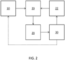
- a system for detecting an analyte may include a container 10 (or more than one container), the thin film resonator 20, actuation circuitry 22, measurement circuitry 29, and control electronics 30.
- a fluid path couples the one or more containers 10 to the resonator 20.
- the control electronics 30 are operably coupled to the actuation circuitry and the measurement circuitry.
- control electronics 30 are configured to modify the frequency at which the actuation circuitry 22 oscillates the resonator 20 based on input from the measurement circuitry 29.
- the container 10 may house an amplification molecule, an amplification element-linked second recognition component or components thereof, and optionally one or more of a tag, an analyte molecule, and a first recognition component.
- Control electronics 30 may control the flow of such reagents from container 10 to resonator 20; e.g. via a pump, vacuum, or the like.
- control electronics 30 may include a processor, controller, memory, or the like.
- Memory may include computer-readable instructions that, when executed by processor or controller cause the device and control electronics to perform various functions attributed to device and control electronics described herein.
- Memory may include any volatile, non-volatile, magnetic, optical, or electrical media, such as a random access memory (RAM), read-only memory (ROM), non-volatile RAM (NVRAM), electrically-erasable programmable ROM (EEPROM), flash memory, or any other digital media.
- RAM random access memory
- ROM read-only memory
- NVRAM non-volatile RAM
- EEPROM electrically-erasable programmable ROM
- flash memory or any other digital media.
- Control electronics 30 may include any one or more of a microprocessor, a controller, a digital signal processor (DSP), an application specific integrated circuit (ASIC), a field-programmable gate array (FPGA), or equivalent discrete or integrated logic circuitry.
- control electronics 30 may include multiple components, such as any combination of one or more microprocessors, one or more controllers, one or more DSPs, one or more ASICs, or one or more FPGAs, as well as other discrete or integrated logic circuitry.
- the functions attributed to control electronics herein may be embodied as software, firmware, hardware or any combination thereof.
- Molecular recognition of a sample comprising a significant background signal may be facilitated by amplification of the signal.
- the systems and methods described herein employ a second recognition component comprising an amplification element such as a linked enzyme.
- the TFBAR sensors at the higher frequency ranges described herein, responded very efficiently to mass increase of the sensor surface due to precipitation of a substrate cleaved by an enzyme.
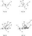
- FIGS. 3A-D schematic drawings illustrating enzyme amplification on a TFBAR are shown.
- a molecular recognition component 100 configured to bind to an analyte is immobilized on a surface 26 of a resonator 20.
- the resonator 20, having immobilized molecular recognition component 100 may be contacted with a composition comprising an analyte 110, which may bind molecular recognition component 100 (see FIG. 3B ).
- the resonator 20, having immobilized molecular recognition component 100 to which analyte 110 is bound may be contacted with a composition comprising a second molecular recognition component 120 linked to an amplification element 130 such as an enzyme.
- the second molecular recognition component 120 is configured to bind to analyte 110 such that the second molecular recognition component 120 and linked amplification element 130 are immobilized relative to the surface 26 (see FIG. 3C ).
- a soluble substrate 140 may be converted by amplification element 130 to an insoluble product 150, which precipitates and accumulates on the surface 26 of the resonator 20, thereby amplifying the mass signal as a function of amount or concentration of bound analyte 110 (see FIG. 3D ).
- the analyte 110 may be contacted with the second molecular recognition component 120 (and bound amplification element 130 ) before the analyte (with bound second molecular recognition component) is contacted to the surface 26 of the resonator 20 relative to which the molecular recognition component 100 is immobilized.
- the substrate 140 may be present at the time the second molecular recognition component 120 - amplification element 130 is added or may be added later. In any case, washing may be performed prior to amplification.
- target analytes include nucleic acids, proteins, peptides, antibodies, enzymes, carbohydrates, chemical compounds, or infectious species such as bacteria, fungi, protozoa, viruses and the like.
- the target analyte is capable of binding more than one molecular recognition component.
- any suitable molecular recognition component may be bound to the surface of a resonator.
- the molecular recognition component preferably selectively binds to the analyte of interest.
- the molecular recognition component may be selected from the group consisting of nucleic acids, nucleotide, nucleoside, nucleic acids analogues such as PNA and LNA molecules, proteins, peptides, antibodies including IgA, IgG, IgM, IgE, lectins, enzymes, enzymes cofactors, enzyme substrates, enzymes inhibitors, receptors, ligands, kinases, Protein A, Poly U, Poly A, Poly lysine, triazine dye, boronic acid, thiol, heparin, polysaccharides, coomassie blue, azure A, metal-binding peptides, sugar, carbohydrate, chelating agents, prokaryotic cells and eukary
- Any suitable method for immobilizing a molecular recognition component on a surface of a TFBAR may be used.
- a uniform coating of epoxy silane may be deposited on the sensor surface using a vapor deposition process.
- Test and reference molecular recognition components such as antibodies, may then be deposited onto the test and reference resonators using, for example, piezo based nanodispensing technology.
- Primary amines on the antibodies react with the epoxide groups covalently binding the antibody to the sensor surface.
- a thiol group, if present, on the molecular recognition component may bind to a surface of the TFBAR.
- the surface of the TFBAR may be modified, as appropriate or necessary, to permit binding of the molecular recognition component.
- any suitable molecular recognition components such as those described above, may be used as the second molecular recognition component (e.g., 120 in FIG. 3 ).
- the second molecular recognition component may be linked to any suitable amplification element, such as an enzyme.
- the second molecular recognition component is an antibody and the amplification element is an enzyme.
- the amplification element may be an activatable polymerization initiator, such as a photoinitiator, a chemical initiator, or a thermoinitiator.
- the polymerization initiator may be activated in the presence of one or more monomers to cause a polymer to graft from the second molecular recognition component.
- the amplification element may be an enzyme.
- the enzyme may be capable of converting a substrate that is soluble in the assay environment to an insoluble product that precipitates on the surface of the sensor. Examples of suitable enzymes include alkaline phosphatase (ALP), horse radish peroxidase (HRP), beta galactosidase, and glucose oxidase.
- Examples of enzyme/substrate systems that are capable of producing an insoluble product which is capable of accumulating on a surface of a TFBAR include alkaline phosphatase and 5-bromo-4-chloro-3-indolylphosphate/nitro-blue tetrazolium chloride (BCIP/NBT).
- BCIP/NBT 5-bromo-4-chloro-3-indolylphosphate/nitro-blue tetrazolium chloride
- the enzymatically catalyzed hydrolysis of BCIP produces an insoluble dimer, which may precipitate on the surface of the sensors.
- Other analogous substrates having the phosphate moiety replaced with such hydrolytically cleavable functionalities as galactose, glucose, fatty acids, fatty acid esters and amino acids can be used with their complementary enzymes.
- peroxidase enzymes for example horse radish peroxidase (HRP) or myeloperoxidase
- HRP horse radish peroxidase
- myeloperoxidase one of the following: benzidene, benzidene dihydrochloride, diaminobenzidene, o-tolidene, o-dianisidine and tetramethyl-benzidene, carbazoles, particularly 3-amino-9-ethylcarbazole, and various phenolic compounds all of which have been reported to form precipitates upon reaction with peroxidases.
- oxidases such as alphahydroxy acid oxidase, aldehyde oxidase, glucose oxidase, L-amino acid oxidase and xanthine oxidase can be used with oxidizable substrate systems such as a phenazine methosulfate-nitriblue tetrazolium mixture.
- the analyte may be modified to include a tag recognizable by the first or second recognition complex, such as a streptavidin tag; biotin tag; a chitin binding protein tag; a maltose binding protein tag; a glutathione-S-transferase tag; a poly(His) tag; an epitope tag such as a Myc tag, a HA tag, or a V5 tag; or the like.
- the tag-linked analyte may include a variant or derivative of the analyte.
- the variant or derivative is a variant or derivative that is selectively recognizable by the first or second molecular recognition component that is configured to recognize the analyte. In some situations, it may be desirable that the variant or derivative analyte have an affinity for the first or second molecular recognition component that is different than the affinity of the non-tag-linked analyte.
- the variant or derivative of the analyte may be a variant or derivative that allows for ease of manufacture of the tag-linked analyte.
- the tag-linked analyte may comprise a recombinant polypeptide, etc.
- the tag-linked analyte molecule may bind a first molecular recognition component immobilized on a surface of a resonator.
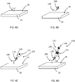
- a signal amplification element 130 may be linked to second recognition component 120 at any suitable time. In some embodiments (not depicted in FIG. 4 ), the signal amplification element 130 is linked to the second recognition component 120 prior to contact with the analyte 110 or the tag-linked analyte molecule. In some of such embodiments, the signal amplification element 130 is covalently bound to the second recognition component 120.
- signal amplification element 130 is linked to secondary recognition component 120 after second recognition component 120 is contacted with the analyte 110 or the tag-linked analyte.
- second recognition component 120 can include first binding partner 123 configured to selectively bind second binding partner of signal amplification element 130.
- First binding partner 123 is preferably covalently bound to second recognition component 120.
- Second binding partner 135 is preferably covalently bound to signal amplification element 130.
- First 123 and second 135 binding partners preferably bind with high affinity.
- first 123 and second 135 binding partners may be employed.
- secondary recognition component 120 can be biotinylated, and signal amplification element 130 may be conjugated to streptavidin; or vice-versa.
- one of first and second binding partners can be a polyhistidine(His) tag
- the other of first and second binding partners can be, for example, a nickel or copper chelator, such as iminodiacetic acid (Ni-IDA) and nitrilotriacetic acid (Ni-NTA) for nickel and carboxylmethylaspartate (Co-CMA) for cobalt, which the poly(His) tag can bind with micromolar affinity.
- Ni-IDA iminodiacetic acid
- Ni-NTA nitrilotriacetic acid
- Co-CMA carboxylmethylaspartate
- first and second binding partners can be a glutathione-S-transferase (GST) tag, and the other of first and second binding partners can be glutathione.
- GST glutathione-S-transferase
- one of first and second binding partners can be a maltose binding protein tag, and the other of first and second binding partners can be amylose or maltose.
- one of first and second binding partners can be a chitin binding protein tag, and the other of first and second binding partners can be chitin. It will be understood that above-presented binding partners are merely examples of high affinity binding partners that may be conjugated to a second recognition component or a signal amplification element and that other binding partners are contemplated herein.
- Binding partners may be conjugated to second recognition component or signal amplification element through any suitable technique.
- chemical conjugation or recombinant techniques may be employed to link a binding partner to second recognition component or signal amplification element, as appropriate.
- Such techniques are well known to those of skill in the art.
- a heterobifunctional cross linker utilizing NHS-ester and maleimide functional groups may be employed as known to those of skill in the art.
- signal amplification element and second recognition component include complementary binding partners
- the signal amplification element may be linked to second recognition component via binding partners at any suitable time.
- signal amplification element 130 may be linked to second recognition component 120 after second recognition component 120 is contacted with analyte 110 or tag-linked analyte.
- signal amplification element 130 containing second binding partner 135 is contacted with second recognition component 120 containing first binding partner 123 before second recognition component 120 is contacted with analyte 110 or tag-linked analyte or at the same time as second recognition component 120 is introduced to resonator.
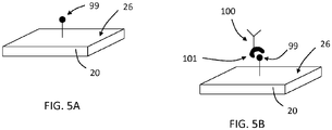
- a first molecular recognition component 100 may be bound to a surface 26 of a TFBAR 20 via one or more intermediate.
- a first binding partner 99 may be bound to the surface 26 and the first molecular recognition component 100 may include a second binding partner 101 configured to selectively bind to the first binding partner 99.
- the binding partners 99, 101 may be binding partners as described above (e.g., with regard to FIG.4 ).
- First recognition component 100 may be bound to surface 26 via binding partners 99, 101 at any suitable time, such as before the sensor 20 is incorporated into a system or after the sensor 20 is incorporated into the system.
- first recognition component 100 may be bound to surface 26 via binding partners 99, 101 as a first step of, or during, an analyte detection assay.
- a TFBAR having a resonance frequency of about 2.2 GHz should afford sufficient sensitivity to detect low concentrations of analytes without the use of signal amplification/mass-loading as described herein.
- the inventors found that even with such high resonance frequencies, TFBAR sensors were not sufficiently sensitive to detect low levels of analyte.
- more of the theoretical gains in sensitivity offered by operating at higher frequencies can be realized.
- Susceptibility to noise is related to signal propagation discussed theoretically above. At higher frequencies the signal propagates shorter distances, thus creating a proximity filter. That is, you only measure what is in proximity to the surface. However, what constitutes proximity will change with frequency and can have important practical ramifications with regard to susceptibility to background noise. Operation at higher frequencies with the mass loading not only results in enhanced signal sensitivity, it also results in lower susceptibility to noise. That can translate functionally to, for example, less stringent washing requirements because the second molecular recognition component linked with the amplification element, that is not bound to the surface of the resonator (e.g., via analyte bound to first molecular recognition component), should not add significant mass in proximity to the surface of the resonator. Furthermore, the washing requirements to obtain a stable baseline reading in negative sample were found to be much less stringent with higher frequency TFBARs, which may also be due to the shorter distance of signal propagation at higher frequency.
- the sensors, devices and systems described herein may be employed to detect an analyte in a sample.
- the sensors may find use in numerous chemical, environmental, food safety, or medial applications.
- a sample to be tested may be, or may be derived from blood, serum, plasma, cerebrospinal fluid, saliva, urine, and the like.
- Other test compositions that are not fluid compositions may be dissolved or suspended in an appropriate solution or solvent for analysis.
- any direction referred to herein, such as “top,” “bottom,” “left,” “right,” “upper,” “lower,” and other directions and orientations are described herein for clarity in reference to the figures and are not to be limiting of an actual device or system or use of the device or system. Devices or systems as described herein may be used in a number of directions and orientations.
- Binding event means the binding of a target analyte to a molecular recognition component immobilized in a surface of a sensor.
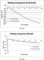
- the testing sequence was as follows, sensors were exposed to 1 ⁇ g/ml Bovine IgG for 60 seconds followed by a 30 second rinse and exposure to a rabbit anti-bovine IgG-alkaline phosphatase conjugate for 60 seconds. Sensors then rinsed 2 times for 30 seconds and exposed to BCIP/NBT substrate for 60 seconds. Sensors electrically connected to a network analyzer which was used to monitor the frequency shift of the devices. In this case, phase resulting in maximum group delay was tracked and change in input frequency to maintain the phase as mass changed was determined. A 50 MHz window around the resonate frequency was collect at a sampling rate of 2 samples per second for both the test and reference resonators. This data was post processed to determine the frequency shift as a function of time for both the test and reference resonators. The frequency shift observed from direct antigen binding was then compared to the signal observed in the enzyme substrate.
- FIG. 4A Results of this initial study are presented in FIG. 4A , with FIG. 4B being a detailed view of a portion of the plot presented in FIG. 4A .
- the ALP-enzyme amplification resulted in significant improvement in sensitivity relative to direct binding without addition of the substrate.
- Table 1 results of ALP-Amplification Direct Binding Enzyme Amplification Response (Integral) -9,024 -1,094,473 Amplification (X) 121 Slope -3.24 -374.77 Slope Amp 115.71
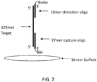
- a 125-mer oligonucleotide was used as a model target.
- the target oligonucleotide was mixed with 6 nM of a 3'biotin labeled 18-mer complementary to the 5' end of the 125-mer target in hybridization buffer (5X SSC, 10% formamide, 0.1% SDS) and reacted with the sensor surface for 4 minutes at 39C.
- FIG. 7 A schematic diagram of the 27-mer bound to the sensor surface and the target 125-mer, which is bound to the biotinylated 18-mer is shown in FIG. 7 .
- Affinity purified goat anti IL-6 (R&D Systems Part Number AF-206-NA) was spotted onto epoxy silane activated sensors (2175 MHz TFBAR) generally as discussed above for the antibody in EXAMPLE 1.
- Mouse monoclonal antibody against IL-6 (R&D Systems Part Number MAB206) was labeled with a 5X molar excess of sulfo-NHS-LC-Biotin (Thermo Scientific) according to the manufacturer's instructions. Excess unincorporated biotin reagent was removed by desalting.
- Calibrator matrix was prepared by mixing 10% (v/v) chicken serum (Equitech, charcoal stripped, heat inactivated) with phosphate buffered saline (PBS) plus 0.1% sodium azide. Calibrators were prepared by diluting recombinant human IL-6 (R&D Systems Part Number 206-IL) in Calibrator matrix.
- SA-ALP alkaline phosphatase
- Wash buffer is Hepes buffered saline plus detergent.
- Substrate is 1-Step NBT/BCIP purchased from Thermo Scientific (Part Number 34042).
- Biotinylated mouse anti IL-6 was diluted to a working strength of 8.3 ⁇ g/mL in a Hepes buffer containing fish skin gelatin (Hepes/FSG).
- SA-ALP was diluted to a working strength of 1 ⁇ g/mL in Hepes/FSG.
Landscapes
- Health & Medical Sciences (AREA)
- Immunology (AREA)
- Life Sciences & Earth Sciences (AREA)
- Engineering & Computer Science (AREA)
- Chemical & Material Sciences (AREA)
- Physics & Mathematics (AREA)
- Biomedical Technology (AREA)
- Pathology (AREA)
- Analytical Chemistry (AREA)
- Hematology (AREA)
- General Physics & Mathematics (AREA)
- Molecular Biology (AREA)
- Urology & Nephrology (AREA)
- General Health & Medical Sciences (AREA)
- Biochemistry (AREA)
- Cell Biology (AREA)
- Medicinal Chemistry (AREA)
- Food Science & Technology (AREA)
- Microbiology (AREA)
- Biotechnology (AREA)
- Acoustics & Sound (AREA)
- Apparatus Associated With Microorganisms And Enzymes (AREA)
- Investigating Or Analyzing Materials By The Use Of Electric Means (AREA)
- Piezo-Electric Or Mechanical Vibrators, Or Delay Or Filter Circuits (AREA)
Claims (12)
- Procédé pour détecter un analyte dans un échantillon, comprenant :l'entrée en contact avec un analyte (110) et optionnellement un analyte lié à étiquette, un premier composant de reconnaissance (100), et un second composant de reconnaissance (120) lié à un élément d'amplification (130) pour générer un complexe comprenant le premier composant de reconnaissance (100) et le second composant de reconnaissance (120) lié à l'élément d'amplification (130),dans lequel le premier composant de reconnaissance (100) est immobilisé sur une surface (26) d'un résonateur acoustique de volume à film mince (TFBAR) (20) ayant une fréquence de résonance de 1,8 GHz ou plus et est configuré pour sélectivement associer un ou plusieurs de l'analyte (110) et optionnellement d'un analyte lié à étiquette associé au second composant de reconnaissance (120),dans lequel le second composant de reconnaissance (120) lié à l'élément d'amplification (130) est configuré pour sélectivement associer l'analyte (110) et optionnellement l'analyte lié à étiquette associé au premier composant de reconnaissance (100) ; etdans lequel le second composant de reconnaissance (120) est conjugué à un premier partenaire d'association (123), l'élément d'amplification (130) est conjugué à un second partenaire d'association (135) configuré pour s'associer sélectivement au premier partenaire d'association (123), et dans lequel l'élément d'amplification (130) est lié au second composant de reconnaissance (120) par le biais d'association entre les premier et second partenaires d'association (123 et 135) ;l'entrée en contact avec l'élément d'amplification (130) lié à un précurseur d'amplification (140) dans des conditions pour convertir le précurseur d'amplification (140) en une molécule (150) qui ajoute une masse au niveau d'une surface (26) du TFBAR (20) ; etla mesure de masse ajoutée au niveau de la surface (26) du TFBAR (20).
- Procédé selon la revendication 1, dans lequel l'analyte (110) ou l'analyte et l'analyte lié à étiquette sont mis en contact avec le second composant de reconnaissance (120) lié à l'élément d'amplification (130) avant le contact avec le premier composant de reconnaissance (100) immobilisé sur la surface (26) du TFBAR (20).
- Procédé selon la revendication 1, dans lequel l'analyte (110) ou l'analyte et l'analyte lié à étiquette sont mis en contact avec le premier composant de reconnaissance (100) avant le contact avec le second composant de reconnaissance (120) lié à l'élément d'amplification (130).
- Procédé selon la revendication 1, dans lequel l'analyte (110) ou l'analyte lié à étiquette, le premier composant de reconnaissance (100) et le second composant de reconnaissance (120) lié à l'élément d'amplification (130) sont mis en contact simultanément.
- Procédé selon l'une quelconque des revendications 1 à 4, dans lequel la mesure de la masse ajoutée à ou associée à la surface (26) du TFBAR (20) comprend :le couplage d'un signal électrique d'entrée au TFBAR (20), le signal électrique d'entrée ayant une fréquence au sein d'une bande de résonance du résonateur piézoélectrique, dans lequel la fréquence est de 1,8 GHz ou plus ;la transmission du signal électrique d'entrée à travers le TFBAR (20), ou par l'intermédiaire de ce dernier, pour générer un signal électrique de sortie ayant une fréquence ;la réception du signal électrique de sortie à partir du TFBAR (20) ; etla détermination d'un changement de déphasage du signal électrique de sortie causé par dépôt du précipité sur la surface (26) du TFBAR (20).
- Procédé selon la revendication 5, dans lequel le changement de déphasage est un changement de déphasage de coefficient d'insertion ou de réflexion.
- Procédé selon l'une quelconque des revendications 1 à 4, dans lequel la mesure de la masse ajoutée à ou associée à la surface (26) du TFBAR (20) comprend :l'actionnement du TFBAR (20) en un mouvement oscillant à une fréquence d'environ 1,8 GHz ou plus ;la mesure d'un ou de plusieurs signaux de sortie de résonateur représentant des caractéristiques de résonance du mouvement oscillant du TFBAR (20) ; etl'ajustement de la fréquence d'actionnement du résonateur de détection pour maintenir un point de résonance du TFBAR (20).
- Procédé selon la revendication 7, dans lequel le point de résonance du TFBAR (20) est un point de temps de propagation de groupe maximum.
- Procédé selon l'une quelconque des revendications 5 à 8, dans lequel la fréquence est de 2 GHz ou plus.
- Procédé selon l'une quelconque des revendications 5 à 8, dans lequel la fréquence est de 2 GHz à 2,5 GHz.
- Procédé selon l'une quelconque des revendications 1 à 10, dans lequel l'élément d'amplification (130) est un enzyme et le précurseur d'amplification (140) est un substrat, et dans lequel l'enzyme est configuré pour convertir le substrat en un précipité.
- Système pour détecter un analyte dans un échantillon, comprenant :un résonateur acoustique de volume à film mince (TFBAR) (20) comprenant une surface (26) sur laquelle un premier composant de reconnaissance (100) est immobilisé,
le premier composant de reconnaissance (100) étant configuré pour sélectivement associer l'analyte (110) et optionnellement un analyte lié à étiquette auquel un second composant de reconnaissance (120) est associé, le TFBAR (20) ayant une fréquence de résonance de 1,8 GHz ou plus ;un ou plusieurs contenants (10) logeant : un précurseur d'amplification (140) ; optionnellement un ou plusieurs de l'étiquette et de l'analyte (110) ; et le second composant de reconnaissance (120) et un élément d'amplification (130), le second composant de reconnaissance (120) étant optionnellement lié à l'élément d'amplification (130), dans lequel le second composant de reconnaissance (120) optionnellement lié à l'élément d'amplification (130) comprend le second composant de reconnaissance (120) conjugué à un premier partenaire d'association (123) et l'élément d'amplification (130) conjugué à un second partenaire d'association (135) qui est configuré pour sélectivement s'associer au premier partenaire d'association (123), dans lequel, durant l'utilisation, l'élément d'amplification (130) est lié au second composant de reconnaissance (120) par le biais d'association des premier et second partenaires d'association (123 et 135) ;un chemin de fluide depuis les un ou plusieurs contenants (10) jusqu'à la surface (26) du TFBAR (20) auquel le premier composant de reconnaissance (100) est associé ;une circuiterie d'actionnement (22) configurée pour entraîner le TFBAR (20) en un mouvement oscillant ;une circuiterie de mesure (29) agencée pour être couplée au TFBAR (20) et configurée pour mesurer un ou plusieurs signaux de sortie de résonateur représentant des caractéristiques de résonance du mouvement oscillant du résonateur de détection ; etune unité de commande (30) fonctionnellement couplée aux circuiteries d'actionnement et de mesure (22 et 29).
Priority Applications (1)
| Application Number | Priority Date | Filing Date | Title |
|---|---|---|---|
| PL15842191T PL3194961T3 (pl) | 2014-09-15 | 2015-09-10 | Cienkowarstwowy rezonator z akustyczną falą objętościową ze wzmocnieniem sygnału |
Applications Claiming Priority (2)
| Application Number | Priority Date | Filing Date | Title |
|---|---|---|---|
| US201462050589P | 2014-09-15 | 2014-09-15 | |
| PCT/US2015/049387 WO2016044055A1 (fr) | 2014-09-15 | 2015-09-10 | Résonateur acoustique à onde de volume en film mince avec réhaussement de signal |
Publications (3)
| Publication Number | Publication Date |
|---|---|
| EP3194961A1 EP3194961A1 (fr) | 2017-07-26 |
| EP3194961A4 EP3194961A4 (fr) | 2018-03-28 |
| EP3194961B1 true EP3194961B1 (fr) | 2021-01-06 |
Family
ID=55533700
Family Applications (1)
| Application Number | Title | Priority Date | Filing Date |
|---|---|---|---|
| EP15842191.7A Active EP3194961B1 (fr) | 2014-09-15 | 2015-09-10 | Résonateur acoustique à onde de volume en film mince avec réhaussement de signal |
Country Status (7)
| Country | Link |
|---|---|
| EP (1) | EP3194961B1 (fr) |
| JP (1) | JP6694434B2 (fr) |
| CN (1) | CN107250794B (fr) |
| DK (1) | DK3194961T3 (fr) |
| ES (1) | ES2863602T3 (fr) |
| PL (1) | PL3194961T3 (fr) |
| WO (1) | WO2016044055A1 (fr) |
Families Citing this family (5)
| Publication number | Priority date | Publication date | Assignee | Title |
|---|---|---|---|---|
| US10234425B2 (en) | 2013-03-15 | 2019-03-19 | Qorvo Us, Inc. | Thin film bulk acoustic resonator with signal enhancement |
| US9835595B2 (en) | 2013-05-23 | 2017-12-05 | Qorvo Us, Inc. | Sensors, methods of making and devices |
| EP3919896B1 (fr) | 2013-05-23 | 2024-07-03 | Zomedica Biotechnologies LLC | Ensemble en deux parties |
| JP2021528664A (ja) * | 2018-07-06 | 2021-10-21 | コーボ ユーエス,インコーポレイティド | ダイナミックレンジが拡大されたバルク音響波共振器 |
| JP2021091758A (ja) * | 2019-12-06 | 2021-06-17 | 国立大学法人九州大学 | 両親媒性物質を含むセンサの洗浄液 |
Family Cites Families (12)
| Publication number | Priority date | Publication date | Assignee | Title |
|---|---|---|---|---|
| US4999284A (en) * | 1988-04-06 | 1991-03-12 | E. I. Du Pont De Nemours And Company | Enzymatically amplified piezoelectric specific binding assay |
| US5932953A (en) * | 1997-06-30 | 1999-08-03 | Iowa State University Research Foundation, Inc. | Method and system for detecting material using piezoelectric resonators |
| AU2003250294A1 (en) | 2002-07-19 | 2004-03-03 | Siemens Aktiengesellschaft | Device and method for detecting a substance with the aid of a high frequency piezo-acoustic thin film resonator |
| CN100495008C (zh) | 2003-06-18 | 2009-06-03 | 中山市泰威技术开发有限公司 | 压电体声波传感器无源式阵列及其生物芯片 |
| US20050148065A1 (en) * | 2003-12-30 | 2005-07-07 | Intel Corporation | Biosensor utilizing a resonator having a functionalized surface |
| JP5020324B2 (ja) * | 2006-08-17 | 2012-09-05 | アトノミックス アクティーゼルスカブ | 目標検体を検出するための、生体表面音響波(saw)共振器増幅 |
| KR20090070886A (ko) * | 2007-12-27 | 2009-07-01 | 삼성전자주식회사 | 압전 센서를 이용한 바이오 센서에서 신호의 주파수변화량을 증폭하는 방법 |
| FR2943787B1 (fr) * | 2009-03-26 | 2012-10-12 | Commissariat Energie Atomique | Micro-dispositif de detection in situ de particules d'interet dans un milieu fluide, et procede de mise en oeuvre |
| DK2630479T3 (da) | 2010-10-20 | 2020-07-20 | Qorvo Us Inc | Anordning og fremgangsmåde til måling af bindingskinetik og koncentration med en resonanssensor |
| TW201411810A (zh) * | 2012-07-16 | 2014-03-16 | Silanna Group Pty Ltd | 薄膜型塊體聲波共振器之cmos製作 |
| CN105431734B (zh) * | 2013-03-15 | 2018-10-02 | 快速诊断技术公司 | 信号增强的薄膜体声波谐振器 |
| PL3194962T3 (pl) * | 2014-09-15 | 2019-09-30 | Qorvo Us, Inc. | Detekcja masy poprzez sprzęganie redoks |
-
2015
- 2015-09-10 PL PL15842191T patent/PL3194961T3/pl unknown
- 2015-09-10 JP JP2017533712A patent/JP6694434B2/ja active Active
- 2015-09-10 ES ES15842191T patent/ES2863602T3/es active Active
- 2015-09-10 DK DK15842191.7T patent/DK3194961T3/da active
- 2015-09-10 WO PCT/US2015/049387 patent/WO2016044055A1/fr active Application Filing
- 2015-09-10 EP EP15842191.7A patent/EP3194961B1/fr active Active
- 2015-09-10 CN CN201580049756.8A patent/CN107250794B/zh active Active
Non-Patent Citations (1)
| Title |
|---|
| None * |
Also Published As
| Publication number | Publication date |
|---|---|
| EP3194961A4 (fr) | 2018-03-28 |
| JP2017527831A (ja) | 2017-09-21 |
| PL3194961T3 (pl) | 2021-08-02 |
| JP6694434B2 (ja) | 2020-05-13 |
| CN107250794B (zh) | 2020-09-15 |
| CN107250794A (zh) | 2017-10-13 |
| WO2016044055A1 (fr) | 2016-03-24 |
| EP3194961A1 (fr) | 2017-07-26 |
| WO2016044055A8 (fr) | 2016-05-26 |
| DK3194961T3 (da) | 2021-03-29 |
| ES2863602T3 (es) | 2021-10-11 |
Similar Documents
| Publication | Publication Date | Title |
|---|---|---|
| US10539537B2 (en) | Thin film bulk acoustic resonator with signal enhancement | |
| EP2972295B1 (fr) | Résonateur acoustique de volume en couche mince ayant une amélioration de signal | |
| JP5020324B2 (ja) | 目標検体を検出するための、生体表面音響波(saw)共振器増幅 | |
| EP3194961B1 (fr) | Résonateur acoustique à onde de volume en film mince avec réhaussement de signal | |
| JP5276655B2 (ja) | 標的検体の検出用のナノ粒子を用いた生体表面弾性波(saw)共振器増幅 | |
| US20240183822A1 (en) | Bulk acoustic wave resonator with increased dynamic range | |
| US7413892B2 (en) | Systems and methods for molecular recognition | |
| US20240033734A1 (en) | Analyte depletion for sensor equilibration | |
| US11747305B2 (en) | Resonator for detecting single molecule binding | |
| US20160291005A1 (en) | Sensors having internal calibration or positive controls | |
| Vijh | Acoustic Wave Based Biosensor |
Legal Events
| Date | Code | Title | Description |
|---|---|---|---|
| STAA | Information on the status of an ep patent application or granted ep patent |
Free format text: STATUS: THE INTERNATIONAL PUBLICATION HAS BEEN MADE |
|
| PUAI | Public reference made under article 153(3) epc to a published international application that has entered the european phase |
Free format text: ORIGINAL CODE: 0009012 |
|
| STAA | Information on the status of an ep patent application or granted ep patent |
Free format text: STATUS: REQUEST FOR EXAMINATION WAS MADE |
|
| 17P | Request for examination filed |
Effective date: 20170310 |
|
| AK | Designated contracting states |
Kind code of ref document: A1 Designated state(s): AL AT BE BG CH CY CZ DE DK EE ES FI FR GB GR HR HU IE IS IT LI LT LU LV MC MK MT NL NO PL PT RO RS SE SI SK SM TR |
|
| AX | Request for extension of the european patent |
Extension state: BA ME |
|
| DAV | Request for validation of the european patent (deleted) | ||
| DAX | Request for extension of the european patent (deleted) | ||
| A4 | Supplementary search report drawn up and despatched |
Effective date: 20180227 |
|
| RIC1 | Information provided on ipc code assigned before grant |
Ipc: G01N 33/543 20060101ALI20180221BHEP Ipc: G01N 31/00 20060101ALI20180221BHEP Ipc: G01N 29/36 20060101ALI20180221BHEP Ipc: G01N 33/53 20060101AFI20180221BHEP Ipc: G01N 29/22 20060101ALI20180221BHEP Ipc: G01N 33/00 20060101ALI20180221BHEP |
|
| STAA | Information on the status of an ep patent application or granted ep patent |
Free format text: STATUS: EXAMINATION IS IN PROGRESS |
|
| 17Q | First examination report despatched |
Effective date: 20181207 |
|
| REG | Reference to a national code |
Ref country code: DE Ref legal event code: R079 Ref document number: 602015064541 Country of ref document: DE Free format text: PREVIOUS MAIN CLASS: G01N0033530000 Ipc: G01N0033543000 |
|
| RIC1 | Information provided on ipc code assigned before grant |
Ipc: G01N 33/543 20060101AFI20200604BHEP Ipc: G01N 33/00 20060101ALI20200604BHEP Ipc: G01N 29/02 20060101ALI20200604BHEP Ipc: G01N 31/00 20060101ALI20200604BHEP Ipc: G01N 29/36 20060101ALI20200604BHEP Ipc: G01N 33/53 20060101ALI20200604BHEP Ipc: G01N 29/22 20060101ALI20200604BHEP |
|
| GRAP | Despatch of communication of intention to grant a patent |
Free format text: ORIGINAL CODE: EPIDOSNIGR1 |
|
| STAA | Information on the status of an ep patent application or granted ep patent |
Free format text: STATUS: GRANT OF PATENT IS INTENDED |
|
| INTG | Intention to grant announced |
Effective date: 20200716 |
|
| GRAS | Grant fee paid |
Free format text: ORIGINAL CODE: EPIDOSNIGR3 |
|
| GRAA | (expected) grant |
Free format text: ORIGINAL CODE: 0009210 |
|
| STAA | Information on the status of an ep patent application or granted ep patent |
Free format text: STATUS: THE PATENT HAS BEEN GRANTED |
|
| AK | Designated contracting states |
Kind code of ref document: B1 Designated state(s): AL AT BE BG CH CY CZ DE DK EE ES FI FR GB GR HR HU IE IS IT LI LT LU LV MC MK MT NL NO PL PT RO RS SE SI SK SM TR |
|
| REG | Reference to a national code |
Ref country code: GB Ref legal event code: FG4D |
|
| REG | Reference to a national code |
Ref country code: AT Ref legal event code: REF Ref document number: 1352931 Country of ref document: AT Kind code of ref document: T Effective date: 20210115 Ref country code: CH Ref legal event code: EP |
|
| REG | Reference to a national code |
Ref country code: DE Ref legal event code: R096 Ref document number: 602015064541 Country of ref document: DE |
|
| REG | Reference to a national code |
Ref country code: IE Ref legal event code: FG4D |
|
| REG | Reference to a national code |
Ref country code: FI Ref legal event code: FGE |
|
| REG | Reference to a national code |
Ref country code: DK Ref legal event code: T3 Effective date: 20210325 |
|
| REG | Reference to a national code |
Ref country code: SE Ref legal event code: TRGR |
|
| REG | Reference to a national code |
Ref country code: NL Ref legal event code: FP |
|
| REG | Reference to a national code |
Ref country code: CH Ref legal event code: NV Representative=s name: ISLER AND PEDRAZZINI AG, CH |
|
| REG | Reference to a national code |
Ref country code: LT Ref legal event code: MG9D |
|
| PG25 | Lapsed in a contracting state [announced via postgrant information from national office to epo] |
Ref country code: GR Free format text: LAPSE BECAUSE OF FAILURE TO SUBMIT A TRANSLATION OF THE DESCRIPTION OR TO PAY THE FEE WITHIN THE PRESCRIBED TIME-LIMIT Effective date: 20210407 Ref country code: HR Free format text: LAPSE BECAUSE OF FAILURE TO SUBMIT A TRANSLATION OF THE DESCRIPTION OR TO PAY THE FEE WITHIN THE PRESCRIBED TIME-LIMIT Effective date: 20210106 Ref country code: BG Free format text: LAPSE BECAUSE OF FAILURE TO SUBMIT A TRANSLATION OF THE DESCRIPTION OR TO PAY THE FEE WITHIN THE PRESCRIBED TIME-LIMIT Effective date: 20210406 Ref country code: NO Free format text: LAPSE BECAUSE OF FAILURE TO SUBMIT A TRANSLATION OF THE DESCRIPTION OR TO PAY THE FEE WITHIN THE PRESCRIBED TIME-LIMIT Effective date: 20210406 Ref country code: PT Free format text: LAPSE BECAUSE OF FAILURE TO SUBMIT A TRANSLATION OF THE DESCRIPTION OR TO PAY THE FEE WITHIN THE PRESCRIBED TIME-LIMIT Effective date: 20210506 Ref country code: LT Free format text: LAPSE BECAUSE OF FAILURE TO SUBMIT A TRANSLATION OF THE DESCRIPTION OR TO PAY THE FEE WITHIN THE PRESCRIBED TIME-LIMIT Effective date: 20210106 |
|
| PG25 | Lapsed in a contracting state [announced via postgrant information from national office to epo] |
Ref country code: RS Free format text: LAPSE BECAUSE OF FAILURE TO SUBMIT A TRANSLATION OF THE DESCRIPTION OR TO PAY THE FEE WITHIN THE PRESCRIBED TIME-LIMIT Effective date: 20210106 Ref country code: LV Free format text: LAPSE BECAUSE OF FAILURE TO SUBMIT A TRANSLATION OF THE DESCRIPTION OR TO PAY THE FEE WITHIN THE PRESCRIBED TIME-LIMIT Effective date: 20210106 |
|
| PG25 | Lapsed in a contracting state [announced via postgrant information from national office to epo] |
Ref country code: IS Free format text: LAPSE BECAUSE OF FAILURE TO SUBMIT A TRANSLATION OF THE DESCRIPTION OR TO PAY THE FEE WITHIN THE PRESCRIBED TIME-LIMIT Effective date: 20210506 |
|
| REG | Reference to a national code |
Ref country code: DE Ref legal event code: R097 Ref document number: 602015064541 Country of ref document: DE |
|
| REG | Reference to a national code |
Ref country code: ES Ref legal event code: FG2A Ref document number: 2863602 Country of ref document: ES Kind code of ref document: T3 Effective date: 20211011 |
|
| PG25 | Lapsed in a contracting state [announced via postgrant information from national office to epo] |
Ref country code: EE Free format text: LAPSE BECAUSE OF FAILURE TO SUBMIT A TRANSLATION OF THE DESCRIPTION OR TO PAY THE FEE WITHIN THE PRESCRIBED TIME-LIMIT Effective date: 20210106 Ref country code: CZ Free format text: LAPSE BECAUSE OF FAILURE TO SUBMIT A TRANSLATION OF THE DESCRIPTION OR TO PAY THE FEE WITHIN THE PRESCRIBED TIME-LIMIT Effective date: 20210106 Ref country code: SM Free format text: LAPSE BECAUSE OF FAILURE TO SUBMIT A TRANSLATION OF THE DESCRIPTION OR TO PAY THE FEE WITHIN THE PRESCRIBED TIME-LIMIT Effective date: 20210106 |
|
| PLBE | No opposition filed within time limit |
Free format text: ORIGINAL CODE: 0009261 |
|
| STAA | Information on the status of an ep patent application or granted ep patent |
Free format text: STATUS: NO OPPOSITION FILED WITHIN TIME LIMIT |
|
| PG25 | Lapsed in a contracting state [announced via postgrant information from national office to epo] |
Ref country code: SK Free format text: LAPSE BECAUSE OF FAILURE TO SUBMIT A TRANSLATION OF THE DESCRIPTION OR TO PAY THE FEE WITHIN THE PRESCRIBED TIME-LIMIT Effective date: 20210106 Ref country code: RO Free format text: LAPSE BECAUSE OF FAILURE TO SUBMIT A TRANSLATION OF THE DESCRIPTION OR TO PAY THE FEE WITHIN THE PRESCRIBED TIME-LIMIT Effective date: 20210106 |
|
| 26N | No opposition filed |
Effective date: 20211007 |
|
| PG25 | Lapsed in a contracting state [announced via postgrant information from national office to epo] |
Ref country code: AL Free format text: LAPSE BECAUSE OF FAILURE TO SUBMIT A TRANSLATION OF THE DESCRIPTION OR TO PAY THE FEE WITHIN THE PRESCRIBED TIME-LIMIT Effective date: 20210106 |
|
| PG25 | Lapsed in a contracting state [announced via postgrant information from national office to epo] |
Ref country code: SI Free format text: LAPSE BECAUSE OF FAILURE TO SUBMIT A TRANSLATION OF THE DESCRIPTION OR TO PAY THE FEE WITHIN THE PRESCRIBED TIME-LIMIT Effective date: 20210106 |
|
| PG25 | Lapsed in a contracting state [announced via postgrant information from national office to epo] |
Ref country code: IS Free format text: LAPSE BECAUSE OF FAILURE TO SUBMIT A TRANSLATION OF THE DESCRIPTION OR TO PAY THE FEE WITHIN THE PRESCRIBED TIME-LIMIT Effective date: 20210506 Ref country code: MC Free format text: LAPSE BECAUSE OF FAILURE TO SUBMIT A TRANSLATION OF THE DESCRIPTION OR TO PAY THE FEE WITHIN THE PRESCRIBED TIME-LIMIT Effective date: 20210106 |
|
| PG25 | Lapsed in a contracting state [announced via postgrant information from national office to epo] |
Ref country code: LU Free format text: LAPSE BECAUSE OF NON-PAYMENT OF DUE FEES Effective date: 20210910 |
|
| REG | Reference to a national code |
Ref country code: AT Ref legal event code: UEP Ref document number: 1352931 Country of ref document: AT Kind code of ref document: T Effective date: 20210106 |
|
| PG25 | Lapsed in a contracting state [announced via postgrant information from national office to epo] |
Ref country code: HU Free format text: LAPSE BECAUSE OF FAILURE TO SUBMIT A TRANSLATION OF THE DESCRIPTION OR TO PAY THE FEE WITHIN THE PRESCRIBED TIME-LIMIT; INVALID AB INITIO Effective date: 20150910 |
|
| P01 | Opt-out of the competence of the unified patent court (upc) registered |
Effective date: 20230503 |
|
| PG25 | Lapsed in a contracting state [announced via postgrant information from national office to epo] |
Ref country code: CY Free format text: LAPSE BECAUSE OF FAILURE TO SUBMIT A TRANSLATION OF THE DESCRIPTION OR TO PAY THE FEE WITHIN THE PRESCRIBED TIME-LIMIT Effective date: 20210106 |
|
| PGFP | Annual fee paid to national office [announced via postgrant information from national office to epo] |
Ref country code: NL Payment date: 20230822 Year of fee payment: 9 |
|
| PGFP | Annual fee paid to national office [announced via postgrant information from national office to epo] |
Ref country code: IT Payment date: 20230822 Year of fee payment: 9 Ref country code: IE Payment date: 20230823 Year of fee payment: 9 Ref country code: GB Payment date: 20230823 Year of fee payment: 9 Ref country code: FI Payment date: 20230823 Year of fee payment: 9 Ref country code: AT Payment date: 20230823 Year of fee payment: 9 |
|
| PGFP | Annual fee paid to national office [announced via postgrant information from national office to epo] |
Ref country code: SE Payment date: 20230822 Year of fee payment: 9 Ref country code: PL Payment date: 20230828 Year of fee payment: 9 Ref country code: FR Payment date: 20230822 Year of fee payment: 9 Ref country code: DK Payment date: 20230822 Year of fee payment: 9 Ref country code: DE Payment date: 20230822 Year of fee payment: 9 Ref country code: BE Payment date: 20230822 Year of fee payment: 9 |
|
| PGFP | Annual fee paid to national office [announced via postgrant information from national office to epo] |
Ref country code: ES Payment date: 20231002 Year of fee payment: 9 |
|
| PGFP | Annual fee paid to national office [announced via postgrant information from national office to epo] |
Ref country code: CH Payment date: 20231001 Year of fee payment: 9 |
|
| PG25 | Lapsed in a contracting state [announced via postgrant information from national office to epo] |
Ref country code: MK Free format text: LAPSE BECAUSE OF FAILURE TO SUBMIT A TRANSLATION OF THE DESCRIPTION OR TO PAY THE FEE WITHIN THE PRESCRIBED TIME-LIMIT Effective date: 20210106 |
|
| REG | Reference to a national code |
Ref country code: GB Ref legal event code: 732E Free format text: REGISTERED BETWEEN 20240516 AND 20240522 |
|
| PG25 | Lapsed in a contracting state [announced via postgrant information from national office to epo] |
Ref country code: TR Free format text: LAPSE BECAUSE OF FAILURE TO SUBMIT A TRANSLATION OF THE DESCRIPTION OR TO PAY THE FEE WITHIN THE PRESCRIBED TIME-LIMIT Effective date: 20210106 |
|
| REG | Reference to a national code |
Ref country code: DE Ref legal event code: R081 Ref document number: 602015064541 Country of ref document: DE Owner name: ZOMEDICA BIOTECHNOLOGIES LLC, PLYMOUTH, US Free format text: FORMER OWNER: QORVO US, INC., GREENSBORO, NC, US |