EP3193748B1 - Weichgewebeschneidegerät - Google Patents
Weichgewebeschneidegerät Download PDFInfo
- Publication number
- EP3193748B1 EP3193748B1 EP15767038.1A EP15767038A EP3193748B1 EP 3193748 B1 EP3193748 B1 EP 3193748B1 EP 15767038 A EP15767038 A EP 15767038A EP 3193748 B1 EP3193748 B1 EP 3193748B1
- Authority
- EP
- European Patent Office
- Prior art keywords
- blade
- shaft
- balloons
- cases
- syringe
- Prior art date
- Legal status (The legal status is an assumption and is not a legal conclusion. Google has not performed a legal analysis and makes no representation as to the accuracy of the status listed.)
- Active
Links
- 210000004872 soft tissue Anatomy 0.000 title description 60
- 210000005117 flexor retinaculum Anatomy 0.000 claims description 69
- 230000007246 mechanism Effects 0.000 claims description 38
- 239000000463 material Substances 0.000 claims description 32
- 230000004913 activation Effects 0.000 claims description 23
- 239000012190 activator Substances 0.000 claims 3
- 239000012530 fluid Substances 0.000 description 26
- 238000000034 method Methods 0.000 description 25
- 230000006835 compression Effects 0.000 description 16
- 238000007906 compression Methods 0.000 description 16
- 238000002604 ultrasonography Methods 0.000 description 16
- 239000007789 gas Substances 0.000 description 14
- 239000000523 sample Substances 0.000 description 11
- 230000006837 decompression Effects 0.000 description 10
- 210000000707 wrist Anatomy 0.000 description 10
- 210000003041 ligament Anatomy 0.000 description 9
- 239000003570 air Substances 0.000 description 8
- 210000001617 median nerve Anatomy 0.000 description 6
- 210000000746 body region Anatomy 0.000 description 5
- 230000001419 dependent effect Effects 0.000 description 5
- 230000008878 coupling Effects 0.000 description 4
- 238000010168 coupling process Methods 0.000 description 4
- 238000005859 coupling reaction Methods 0.000 description 4
- 210000003811 finger Anatomy 0.000 description 4
- 210000001519 tissue Anatomy 0.000 description 4
- XLYOFNOQVPJJNP-UHFFFAOYSA-N water Substances O XLYOFNOQVPJJNP-UHFFFAOYSA-N 0.000 description 4
- 208000027418 Wounds and injury Diseases 0.000 description 3
- 230000006378 damage Effects 0.000 description 3
- 208000014674 injury Diseases 0.000 description 3
- 210000005036 nerve Anatomy 0.000 description 3
- 210000003813 thumb Anatomy 0.000 description 3
- 210000002559 ulnar artery Anatomy 0.000 description 3
- 238000012800 visualization Methods 0.000 description 3
- FAPWRFPIFSIZLT-UHFFFAOYSA-M Sodium chloride Chemical compound [Na+].[Cl-] FAPWRFPIFSIZLT-UHFFFAOYSA-M 0.000 description 2
- 208000003295 carpal tunnel syndrome Diseases 0.000 description 2
- 210000004247 hand Anatomy 0.000 description 2
- 239000007788 liquid Substances 0.000 description 2
- 210000004977 neurovascular bundle Anatomy 0.000 description 2
- 239000013307 optical fiber Substances 0.000 description 2
- 230000008569 process Effects 0.000 description 2
- 239000011780 sodium chloride Substances 0.000 description 2
- 238000001356 surgical procedure Methods 0.000 description 2
- 210000002435 tendon Anatomy 0.000 description 2
- 206010060965 Arterial stenosis Diseases 0.000 description 1
- 206010029174 Nerve compression Diseases 0.000 description 1
- 230000003466 anti-cipated effect Effects 0.000 description 1
- 238000004891 communication Methods 0.000 description 1
- 230000000916 dilatatory effect Effects 0.000 description 1
- 238000006073 displacement reaction Methods 0.000 description 1
- 210000004165 myocardium Anatomy 0.000 description 1
- 230000000087 stabilizing effect Effects 0.000 description 1
Images


Classifications
-
- A—HUMAN NECESSITIES
- A61—MEDICAL OR VETERINARY SCIENCE; HYGIENE
- A61B—DIAGNOSIS; SURGERY; IDENTIFICATION
- A61B17/00—Surgical instruments, devices or methods, e.g. tourniquets
- A61B17/32—Surgical cutting instruments
- A61B17/320016—Endoscopic cutting instruments, e.g. arthroscopes, resectoscopes
- A61B17/320036—Endoscopic cutting instruments, e.g. arthroscopes, resectoscopes adapted for use within the carpal tunnel
-
- A—HUMAN NECESSITIES
- A61—MEDICAL OR VETERINARY SCIENCE; HYGIENE
- A61B—DIAGNOSIS; SURGERY; IDENTIFICATION
- A61B17/00—Surgical instruments, devices or methods, e.g. tourniquets
- A61B17/32—Surgical cutting instruments
- A61B17/320016—Endoscopic cutting instruments, e.g. arthroscopes, resectoscopes
-
- A—HUMAN NECESSITIES
- A61—MEDICAL OR VETERINARY SCIENCE; HYGIENE
- A61B—DIAGNOSIS; SURGERY; IDENTIFICATION
- A61B17/00—Surgical instruments, devices or methods, e.g. tourniquets
- A61B17/22—Implements for squeezing-off ulcers or the like on the inside of inner organs of the body; Implements for scraping-out cavities of body organs, e.g. bones; Calculus removers; Calculus smashing apparatus; Apparatus for removing obstructions in blood vessels, not otherwise provided for
- A61B2017/22051—Implements for squeezing-off ulcers or the like on the inside of inner organs of the body; Implements for scraping-out cavities of body organs, e.g. bones; Calculus removers; Calculus smashing apparatus; Apparatus for removing obstructions in blood vessels, not otherwise provided for with an inflatable part, e.g. balloon, for positioning, blocking, or immobilisation
- A61B2017/22061—Implements for squeezing-off ulcers or the like on the inside of inner organs of the body; Implements for scraping-out cavities of body organs, e.g. bones; Calculus removers; Calculus smashing apparatus; Apparatus for removing obstructions in blood vessels, not otherwise provided for with an inflatable part, e.g. balloon, for positioning, blocking, or immobilisation for spreading elements apart
-
- A—HUMAN NECESSITIES
- A61—MEDICAL OR VETERINARY SCIENCE; HYGIENE
- A61B—DIAGNOSIS; SURGERY; IDENTIFICATION
- A61B17/00—Surgical instruments, devices or methods, e.g. tourniquets
- A61B17/22—Implements for squeezing-off ulcers or the like on the inside of inner organs of the body; Implements for scraping-out cavities of body organs, e.g. bones; Calculus removers; Calculus smashing apparatus; Apparatus for removing obstructions in blood vessels, not otherwise provided for
- A61B2017/22051—Implements for squeezing-off ulcers or the like on the inside of inner organs of the body; Implements for scraping-out cavities of body organs, e.g. bones; Calculus removers; Calculus smashing apparatus; Apparatus for removing obstructions in blood vessels, not otherwise provided for with an inflatable part, e.g. balloon, for positioning, blocking, or immobilisation
- A61B2017/22065—Functions of balloons
-
- A—HUMAN NECESSITIES
- A61—MEDICAL OR VETERINARY SCIENCE; HYGIENE
- A61B—DIAGNOSIS; SURGERY; IDENTIFICATION
- A61B17/00—Surgical instruments, devices or methods, e.g. tourniquets
- A61B17/30—Surgical pincettes without pivotal connections
- A61B2017/306—Surgical pincettes without pivotal connections holding by means of suction
-
- A—HUMAN NECESSITIES
- A61—MEDICAL OR VETERINARY SCIENCE; HYGIENE
- A61B—DIAGNOSIS; SURGERY; IDENTIFICATION
- A61B17/00—Surgical instruments, devices or methods, e.g. tourniquets
- A61B17/32—Surgical cutting instruments
- A61B2017/320044—Blunt dissectors
- A61B2017/320048—Balloon dissectors
-
- A—HUMAN NECESSITIES
- A61—MEDICAL OR VETERINARY SCIENCE; HYGIENE
- A61B—DIAGNOSIS; SURGERY; IDENTIFICATION
- A61B90/00—Instruments, implements or accessories specially adapted for surgery or diagnosis and not covered by any of the groups A61B1/00 - A61B50/00, e.g. for luxation treatment or for protecting wound edges
- A61B90/08—Accessories or related features not otherwise provided for
- A61B2090/0801—Prevention of accidental cutting or pricking
-
- A—HUMAN NECESSITIES
- A61—MEDICAL OR VETERINARY SCIENCE; HYGIENE
- A61B—DIAGNOSIS; SURGERY; IDENTIFICATION
- A61B2217/00—General characteristics of surgical instruments
- A61B2217/002—Auxiliary appliance
- A61B2217/005—Auxiliary appliance with suction drainage system
-
- A—HUMAN NECESSITIES
- A61—MEDICAL OR VETERINARY SCIENCE; HYGIENE
- A61M—DEVICES FOR INTRODUCING MEDIA INTO, OR ONTO, THE BODY; DEVICES FOR TRANSDUCING BODY MEDIA OR FOR TAKING MEDIA FROM THE BODY; DEVICES FOR PRODUCING OR ENDING SLEEP OR STUPOR
- A61M25/00—Catheters; Hollow probes
- A61M25/10—Balloon catheters
- A61M25/1018—Balloon inflating or inflation-control devices
- A61M25/10181—Means for forcing inflation fluid into the balloon
- A61M25/10182—Injector syringes
Definitions
- the present invention relates generally to a transverse carpal ligament cutting device.
- Carpal tunnel syndrome affects approximately 3.7% of the general population and up to 7% of manual labor workers.
- CTR procedure A primary goal of the CTR procedure is to cut a transverse carpal ligament in order to reduce median nerve compression and carpal tunnel pressures in the carpal tunnel region.
- CTR procedures can be performed by accessing the carpal tunnel primarily from the outside or accessing the carpal tunnel primarily from the inside.
- a palmar incision of various sizes is used to directly visualize and transect the transverse carpal ligament.
- the transverse carpal ligament is visualized from within the carpal tunnel using an endoscope advanced through a small palmar and/or distal wrist incision -endoscopic carpal tunnel release (ECTR).
- ECTR distal wrist incision -endoscopic carpal tunnel release
- CTR procedures One concern with CTR procedures is that it is hard to visualize the transverse carpal ligament and at-risk structures nearby (e.g., a median nerve and an ulnar artery). It is also hard to visualize individual anatomical variations in the carpal tunnel region. As a result, some CTR procedures can cause incomplete release of the transverse carpal ligament and others can cause injuries to the nearby at-risk structures.
- This narrow space is a "safe zone" in which the transverse carpal tunnel ligament can be cut without risk to the median nerve or ulnar artery.
- This space is variable from patient to patient and can be less than 3 millimeters in some patients. Consequently, placing a sharp cutting instrument in this region can expose a patient to risks of injury. It would also be desirable to provide a device that can expand the "safe zone" in a patient to reduce risks of injury.
- US 5769865 discloses the use of a cannula that can be inserted into the carpal tunnel of a patient through which a cutting device can be inserted.
- the cannula includes an inflatable balloon at its distal end to secure the cutting device against the carpal ligament.
- US 2009/125044 relates to a device and method for dilating a coronary arterial stenosis and for creating a transection in the myocardium.
- the cutting and alignment means may be advanced through a catheter that is located in a patient.
- the outer distal end of the catheter may include a stiff flexible material that acts as an expander.
- US 5425355 discloses a surgical instrument including a probe having a rigid or semi-rigid conduit, through which energy can be delivered for the transection, incision or treatment of a surgical site of the body.
- US 5569283 discloses s surgical cutting instrument for an endoscopic procedure, such as a carpal tunnel release.
- the cutting instrument includes a tubular sheath or obturator connected to a handle, and a cutting blade that is moved from a first protected or enclosed position to a second armed position in which the blade edge is exposed at an opening of the tubular sheath or obturator.
- the cutting edge of the blade is on the proximal side of the blade.
- the blade In the first position, the blade is moved to a distal position in which it is within a shroud at the distal end of the device.
- the blade is moved proximally into the armed position, in which the cutting edge of the blade is moved proximally to remove this from the distal shroud, and create an exposed cutting surface facing proximally.
- US 2010/125266 discloses a treatment device that includes an expandable member at its distal end that can be positioned in a space surrounding a nerve and expanded o stretch the soft tissue around the nerve the relieve pressure exerted by the soft tissue on the nerve.
- US 2012/016398 discloses a carpal tunnel release tool that includes a guide with an angled track and a knife that fits into and follows the angled track. As the knife is advanced along the track, this is retracted into the guide to cut a ligament, or is extended outwardly from the surface of the track.
- the track includes a single inclined surface.
- US 2010/0100114 discloses a surgical instrument with a handle and a tubular member, the distal portion of which includes an access window formed through the wall of the tubular member in communication with the lumen of the tubular member.
- a balloon catheter is mounted in the lumen and expands through the access window when the balloon is inflated.
- US 5735865 discloses a cutting tool with a rigid tubular shank that is guided within a tubular longitudinally slotted instrument shank that has an oval inner cross section.
- the cutting tool may be tilted out of the axis of the instrument shank so that the cutter of the cutting tool penetrates the longitudinal slot of the instrument shank and projects beyond the outer diameter of the instrument shank.
- the angle at which the cutting tool is tilted will set the cutting depth of the cutting tool. This means that the cutting depth and the cutting procedure is exclusively defined by the touch of the operator.
- transverse carpal ligament cutting device according to claim 1.
- a soft tissue cutting device includes a proximal end and a distal end.
- the proximal end is configured to enable an operator to control various functions on the distal end.
- the distal end is configured to perform various functions, including cutting soft tissue in a body.
- the soft tissue cutting device can be used to cut any desired soft tissue in the body.
- the soft tissue cutting device is a transverse carpal ligament cutting device that cuts a transverse carpal ligament in a carpal tunnel region.
- the device includes a proximal end.
- the proximal end includes one or more controls that control various functions on the distal end.
- the controls activate movement of a blade.
- the controls activate inflating and deflating of balloons.
- the controls activate suction through a passage.
- the proximal end includes a single-hand handpiece.
- the single-hand handpiece has a configuration that allows an operator to operate the device using a single hand only.
- the single-hand handpiece is configured as a gun-like handpiece.
- the single-hand handpiece is a gun-like handpiece that includes the one or more controls in a trigger area such that the operator can grip the handpiece while operating the one or more controls with fingers.
- the single-hand handpiece is configured as a handle.
- the single-hand handpiece is a handle that includes one or more controls in a thumb area such that the operator can use a thumb to operate one or more controls.
- the single-hand handle also includes one or more clamp-like controls in an area such that the operator can use a hand to clamp the controls.
- the single-hand handpiece is a handle that includes one or more controls on an inferior position of the handle such that the operator can use a finger to operate one or more controls.
- skilled artisans will understand that the single-hand handpiece is merely one embodiment and is not required. Alternately, two hands or even two operators can operate the present device.
- the handpiece is coupled to a shaft that extends distally towards a distal end.
- the handpiece can be coupled to the shaft using a variety of different configurations.
- the handpiece and shaft have a permanent junction.
- the handpiece and shaft can have a set angular junction or a set straight junction.
- the handpiece and shaft have an adjustable junction that can be adjusted to accommodate operator preference.
- the handpiece and shaft have a rotatable junction that can be rotated to accommodate operator preference.
- the handpiece and shaft can have a junction that is adjustable in length or angulation or rotation.
- the handpiece and the shaft can have a removable junction so that the handpiece and the shaft are removable from one another.
- the shaft has any desired cross-section shape.
- the shaft has a circular cross-section shape.
- the shaft has a non-circular cross section shape.
- the shaft has a squared cross section shape, rectangular cross section shape or squared with round edges cross section shape.
- the shaft can maintain the same cross-section shape or it can assume a different cross-section shape. For example, in some cases, as the shaft extends from the proximal end to the distal end, it maintains a circular cross-section. In other cases, as the shaft extends from the proximal end to the distal end, it changes from a circular cross-section to a non-circular cross section. In yet other cases, as the shaft extends from the proximal end to the distal end, it maintains a non-circular cross section. In further cases, as the shaft extends from the proximal end to the distal end, it changes from a non-circular cross-section to a circular cross-section.
- the shaft can also be provided as a single piece or as a plurality of different pieces. In some cases, the shaft extends from the proximal end to the distal end as a single piece. In other cases, the shaft extends from the proximal end to the distal end as a plurality of pieces.
- the shaft is also formed of any desired medically acceptable material.
- the shaft also has any desired size that is suitable for the medical procedure being performed. As the shaft extends from the proximal end to the distal end, it can maintain the same diameter or it can assume a different diameter. In some cases, as the shaft extends from the proximal end to the distal end, it increases in diameter.
- the device also includes a distal end.
- the distal end is the working end that inserts into the body region of a patient.
- the distal end includes the shaft, a tip, a shaft opening, a blade, and one or more radially expanding balloons. In some cases, the distal end also includes one or more suction openings.
- the shaft at the distal end has a size and cross-section shape that is suitable for being inserted into the body region of interest.
- the shaft extends longitudinally along a longitudinal axis.
- the shaft also has a top surface, side surfaces and a bottom surface.
- Each of the top surface, side surfaces, and bottom surface can be made up of a single wall or a plurality of walls. Additionally, each wall can be a straight wall or a curved wall.
- the shaft is circular, such that the top quarter of the circle forms the top surface, the bottom quarter of the circle forms the bottom surface, and the remaining quarters form the side surfaces. In other cases, the shaft is non-circular.
- the shaft also has a surface that is destined to be positioned adjacent (or even in direct contact with) the soft tissue being cut. In some cases, the top surface is the surface destined to be positioned adjacent the soft tissue.
- the distal end also includes a tip.
- the tip is the distal-most end of the device and is positioned distally to the shaft. In some cases, the tip is an extension of the shaft. In other cases, the tip is a separate piece that is positioned on the distal end of the shaft.
- the tip can have any size or shape that guides the distal end to the body region. In some embodiments, the tip has a rounded configuration, ovoid configuration, pointed configuration or conical configuration.
- the tip is an echogenic tip and includes an ultrasound probe, camera or one or more optical fiber elements to transmit light to or from the distal region of the tip to the proximal portion of the device and is sized and shaped to house an ultrasound probe, camera or one or more optical fiber elements.
- the shaft also includes a shaft opening.
- the shaft opening extends along a longitudinal axis for a distance longitudinally along the shaft.
- the shaft opening also extends along the shaft surface that is destined to be positioned adjacent to or in direct contact with the soft tissue being cut.
- the shaft opening extends longitudinally along the top surface and two side surfaces, so that the shaft opening is open superiorly, medially and laterally. This results in an "open” shaft opening.
- the shaft opening extends longitudinally only along the top surface, so that the shaft opening is only open superiorly. This results in a "closed” shaft opening.
- the shaft also houses a blade.
- the blade includes a working end that has a cutting edge that is configured to cut the soft tissue.
- the cutting edge can have any desired configuration that cuts soft tissue.
- the cutting edge has a sharp straight edge.
- the cutting edge has a sharp curved edge.
- the cutting edge has an angulated, toothed or sawed edge. The cutting edge extends through the shaft opening when the device is in an active position and is protected within the shaft when the device is in an inactive position.
- the blade is also movable with respect to the shaft using any number of different mechanisms.
- the blade is movable by inflating and deflating a blade balloon elevator.
- the blade balloon elevator raises the blade out of the shaft and lowers the blade back into the shaft.
- the blade is movable by moving the blade along a blade guideway.
- the blade guideway can also have a number of different configurations.
- the blade guideway is a substantially flat guide rail.
- the blade guideway includes a one or more ramps or inclines.
- blade guideway has an adjustable height, allowing an operator to increase or decrease cutting depths. Different patients have different transverse carpal tunnel thicknesses and an adjustable blade guideway allows an operator to adjust for these different thicknesses.
- the blade guideway height can be adjusted using any desired adjustment mechanism. In certain cases, the blade guideway height is adjusted by changing the angle of the ramps or inclines. In other cases, the blade guideway height is adjusted using a balloon elevator.
- the shaft also includes one or more balloons that expand radially outwardly from the shaft.
- the balloons serve a number of different purposes. First, the balloons help to anchor the device within the body region to provide stability during cutting of the soft tissue. Also, the balloons help to push nearby at-risk structures away from the device during cutting. This helps to ensure that only the desired soft tissue is cut and that nearby at-risk structures are not cut.
- the shaft can have any desired number of radially-expanding balloons.
- the shaft includes a lateral balloon that expands radially outwardly from one of the two side walls.
- the shaft includes a dorsal balloon that expands radially outwardly from the bottom wall. Skilled artisans will understand that the shaft can have any desired number of lateral and/or dorsal balloons.
- the distal tip includes one or more balloons that expand radially outward from the distal tip.
- the distal tip can include any desired number of radially-expanding balloons.
- the distal tip includes a dorsal balloon that expands radially outward form a bottom surface of the tip. These balloons serve the same purposes as the balloons that expand from the shaft.
- the balloons When inflated, the balloons can have any desired configuration. In some cases, the balloons have a spherical configuration. In other cases, the balloons have an oval configuration. In yet other cases, the balloons have a bilobular configuration.
- the balloons can also be inflated and deflated using a number of different techniques.
- an inflation device supplies inflation material to inflate the balloons and removes inflation material to deflate the balloons.
- the inflation material can be a gas (e.g., air) or a liquid or fluid (e.g., water or saline).
- the balloons can also inflate to a desired size selected to accommodate the patient body area of interest.
- the balloons can be provided with a specific size such that when they are fully inflated, they have a specific inflated size.
- the balloons can have a standard size but can be partially inflated or fully inflated to have a variety of different inflated sizes.
- the balloon inflation can be graded to allow the operator to choose a particular balloon diameter.
- the balloon inflation can be pressure dependent, such that the balloon manually or automatically inflates until a specific pressure is exerted on the balloon surface.
- the inflation device supplies inflation material to the balloons using any desired arrangement.
- the shaft includes one or more conduits operably coupled to both the balloons and the inflation device to deliver and remove gas/fluid to and from the balloons.
- a single conduit is used to deliver and remove gas/fluid to and from the balloons.
- a plurality of conduits can be used.
- a first conduit can deliver and remove gas/fluid to and from a first balloon while a second conduit can deliver and remove gas/fluid to and from a second balloon.
- a first conduit can deliver gas/fluid to all of the balloons while a second conduit can remove gas/fluid from all of the balloons. Skilled artisans will understand that any arrangement of conduits can be used.
- the distal end also includes a plurality of suction openings.
- the suction openings can be provided along the shaft surface that is destined to be positioned adjacent to or in direct contact with the soft tissue being cut.
- the suction openings are provided along a top surface of the shaft.
- the suction openings can have any desired configuration.
- the suction openings are circular holes.
- the suction openings are slots.
- the suction openings are provided as a single elongated slot that extends along a shaft longitudinal axis.
- Suction is applied to the suction openings to suck air through the suction openings. This causes soft tissue near the suction openings to move closer to the surface.
- Suction can be applied to the suction openings using any desired mechanism.
- the shaft includes one or more conduits operably coupled to the suction openings to apply suction to the suction openings.
- a single conduit is used to apply suction to the suction openings.
- a plurality of conduits can be used.
- a first conduit can apply suction to some of the suction openings and a second conduit can apply suction to other of the suction openings. Skilled artisans will understand that any arrangement of conduits can be used.
- the distal tip includes a portion that expands and contracts so the tip can be inserted into the body with a smaller cross-section and then expanded once in the body to a larger cross-section.
- the portion that expands and contracts is an outer shell provided on the distal tip.
- the outer shell can be provided along a portion of the shaft (or the entire shaft) to expand radially outward when positioned in the body to create a greater distance between the central/ventral portion of the device when the knife is exposed during activation.
- Such an outer shell provides even further protection to the body structures near the tissue being cut.
- the outer shell can expand and contract using any known mechanism.
- the outer shell includes a firm material. In other cases, the outer shell includes a malleable material.
- Mechanisms that expand/contract an outer shell include but are not limited to a coil, wedge and sleeve mechanism, a sliding wedge bolt mechanism, an expansion-shell bolt mechanism, slot and wedge bolt mechanism, and a balloon expander/contracter mechanism. Skilled artisans will also understand that any number of outer shells can be provided on the distal tip.
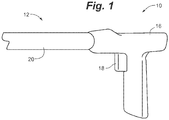
- FIGS. 1-7 illustrate a transverse carpal ligament cutting device 10 according to an embodiment.
- the device 10 has a proximal end 12 and a distal end 14.
- the proximal end 12 can have any configuration to enable an operator to control various functions on the distal end 14.
- the proximal end 12 includes a single-hand handpiece according to any desired configuration.
- the distal end 14 is configured to perform various functions, including cutting a transverse carpal ligament in a carpal tunnel region.
- FIG. 1 illustrates a side view of a proximal end 12 according to an embodiment.
- the proximal end 12 includes a single-hand handpiece 16.
- the single-hand handpiece 16 has a configuration that allows an operator to operate the device 10 using a single hand only.
- the handpiece 16 can have any desired handpiece configuration.
- the handpiece is configured as a gun-like handpiece.
- the handpiece can instead have any other embodiment described herein for a handpiece.
- the handpiece can instead be configured as a handle 216, 316 as shown in any of FIGs. 14 , 28 and 29 .
- the handpiece 16 is configured as a gun-like handpiece that includes the one or more controls 18 in a trigger area such that the operator can grip the handpiece 16 while operating the one or more controls with fingers.
- the controls 18 activate movement of a blade.
- the controls 18 activate inflating and deflating of balloons.
- the controls 18 activate suction through a passage.
- the handpiece 16 is coupled to a shaft 20 that extends distally towards a distal end.
- the handpiece 16 can be coupled to the shaft 20 using a variety of different configurations.
- the handpiece 16 and shaft 20 have a permanent junction.
- the handpiece 16 and shaft 20 can have a set angular junction or a set straight junction.
- the handpiece 16 and shaft 20 have an adjustable junction that can be adjusted to accommodate operator preference.
- the handpiece 16 and shaft 20 can have a junction that is adjustable in length or angulation.
- the handpiece 16 and the shaft 20 can have a removable junction so that the handpiece 16 and the shaft 20 are removable from one another.
- the shaft 20 has any desired cross-section shape. As the shaft 20 extends from the proximal end 12 towards the distal end 14, it can maintain the same cross-section shape or it can assume a different cross-section shape. In some cases, as the shaft 20 extends from the proximal end 12 to the distal end 14, it maintains a circular cross-section. In other cases, as the shaft 20 extends from the proximal end 12 to the distal end 14, it changes from a circular cross-section to a non-circular cross section. In yet other cases, as the shaft 20 extends from the proximal end 12 to the distal end 14, it maintains a non-circular cross section. In further cases, as the shaft 20 extends from the proximal end 12 to the distal end 14, it changes from a non-circular cross-section to a circular cross-section.
- the shaft 20 can also be provided as a single piece or as a plurality of different pieces. In some cases, the shaft 20 extends from the proximal end 12 to the distal end 14 as a single piece. In other cases, the shaft 20 extends from the proximal end 12 to the distal end 14 as a plurality of pieces.
- the shaft 20 is also formed of any desired medically acceptable material.
- the shaft 20 also has any desired size that is suitable for performing a CTR procedure. As the shaft 20 extends from the proximal end 12 to the distal end 14, it can maintain the same diameter or it can assume a different diameter. In some cases, as the shaft 20 extends from the proximal end 12 to the distal end 14, it increases in diameter.
- the device 10 includes a distal end 14 that is the working end that inserts into the carpal tunnel region.
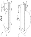
- FIGs. 2-7 illustrate views of a distal end 14 according to one embodiment.
- the distal end 14 includes a shaft 20, tip 22, a shaft opening 24, a blade 26, a blade guideway 28, a blade stop 30, a first lateral balloon 34a and a second lateral balloon 34b.
- Each of these components work together to safely cut a transverse carpal ligament in a carpal tunnel region.
- the distal end 14 includes a shaft 20 that has a size and cross-section shape that is suitable for being inserted into the carpal tunnel region.
- the shaft 20 extends longitudinally along a longitudinal axis "x."
- the shaft 20 has a top surface 40, side surfaces 42, 44, and a bottom surface 46.
- the shaft 20 has a non-circular cross-section such that top surface 40 includes a single top wall, the side surfaces 42, 44 include two side walls, and the bottom surface 46 includes three side walls.
- the shaft 20 can include any other desired cross-section and that each shaft surface can include any desired number of side walls.
- the distal end 14 includes a tip 22.
- the tip 22 is the distal-most end of the device 10 and is positioned distally to the shaft 20. In some cases, the tip 22 is an extension of the shaft 20. In other cases, the tip 22 is a separate piece that is positioned on the distal end of the shaft.
- the tip 22 can have any size or shape that guides the distal end 14 through the carpal tunnel area. In this first embodiment, the tip 22 has a pointed configuration. Of course, the tip 22 can have any other desired configuration.
- the tip 22 is an echogenic tip to improve visualization. In some cases, the echogenic tip includes an ultrasound probe and is sized and shaped to house an ultrasound probe.
- the shaft 20 also includes a shaft opening 24.
- the shaft opening 24 also extends for a distance longitudinally along the surface that is destined to be positioned adjacent to or in direct contact with the transverse carpal tunnel ligament.
- the shaft opening 24 extends along the top surface 40 and two side surfaces 42, 44 so that the shaft opening 24 is open superiorly, medially and laterally. This results in an "open" shaft opening 24.
- the shaft 20 also houses a blade 26.
- the blade 26 includes a cutting edge 32 that is configured to cut a transverse carpal ligament.
- the cutting edge 32 is a distal most edge of the blade 26.
- the cutting edge 32 can have any desired configuration that cuts a transverse carpal ligament.
- the cutting edge 32 has a sharp angulated edge. However, this is not required and the cutting edge 32 can have any other desired configuration.
- the shaft 20 also includes a blade guideway 28 that guides movement of the blade 26.
- the blade guideway 28 can be configured as a guide rail or as a tunnel.
- the blade guideway 28 is configured as a guide rail that extends in a direction parallel to the longitudinal axis x.
- the guide rail is a substantially flat guide rail.
- the shaft 20 includes a blade stop 30 that stops movement of the blade 26. In some cases, the blade stop 30 is sized and shaped to receive the cutting edge 32.
- the blade 26 moves longitudinally along the "x" axis along the guide rail 28 in a forward distal direction and backward proximal direction. As the blade 26 moves forward distally, the cutting edge 32 moves towards the blade stop 30. Likewise, as the blade 26 moves backward proximally, the cutting edge 32 moves away from the blade stop 30.
- the blade 26 can perform cutting as an operator moves the blade proximally or distally or both.
- the shaft 20 also includes one or more balloons that expand or inflate radially outwardly from the shaft 20.
- This first embodiment illustrates two lateral balloons 34a, 34b.
- the balloons 34a, 34b inflate and expand outward laterally from the shaft 20.
- the balloons 34a, 34b deflate and shrink inwardly toward the shaft 20.
- the balloons 34a, 34b When inflated, the balloons 34a, 34b have a spherical, oval, bilobular or other configuration. When deflated, the balloons 34a, 34b are generally flush with the shaft 20.
- any number of radially expanding balloons can be used and be placed anywhere about the shaft 20 to secure the distal end 14 in position within the carpal tunnel region and to expand the "safe zone.” As the radially expanding balloons inflate, they move the flexor tendons, median nerve, and ulnar neurovascular bundle away from the device 10, effectively increasing the "safe zone.” This helps to ensure that only the transverse carpal ligament is cut and that nearby at-risk structures are not cut.
- the distal tip 22 includes one or more balloons that expand radially outward from the distal tip 22.
- the first embodiment does not use such a distal tip balloon.
- skilled artisans will understand that such a distal tip balloon can be used to increase the distal "safe zone" between the tip and the superficial palmar arch and/or further pushes the tip superiorly (i.e. palmarly) to engage the distal end of the transverse carpal ligament.
- the balloons 34a, 34b can also be inflated and deflated using a number of different techniques.
- an inflation device supplies an inflation material to the balloons.
- the inflation material can be a gas (e.g., air) or a fluid or liquid (e.g., water or saline).
- the inflation device supplies inflation material to the balloons 34a, 34b using any desired arrangement.
- the shaft includes one or more conduits operably coupled to both the balloons and the inflation device to deliver and remove gas/fluid to and from the balloons.
- the shaft 20 includes a conduit 50 that delivers and removes gas or fluid from the balloons 34a, 34b.
- conduit 50 that delivers and removes gas or fluid from the balloons 34a, 34b.
- the balloons 34a, 34b can be made expandable using any number of desired configurations. In some cases, the entire balloon is expandable and thus inflates and deflates. In other cases, only part of the balloon is expandable.
- the balloon can have a fixed portion and an expandable portion. The fixed portion can be the portion that directly attaches to a conduit whereas the expandable portion does not directly attach to a conduit and instead expands freely of the conduit.
- the balloons 34a, 34b also inflate to a desired size selected to accommodate the size of a patient's wrist (and thus the patient's carpal tunnel region).
- the balloons can be provided with a specific size such that when they are fully inflated, they have a specific inflated size.
- each of the balloons 34a, 34b inflate to a similar or same diameter (e.g., a diameter of about 1.5mm). In patients with larger wrists, larger balloons can be used. In patients with smaller wrists, smaller balloons can be used.
- one of the balloons 34a, 34b inflates to one size and the other inflates to a different size.
- the balloons 34a, 34b can have a standard size but can be partially inflated or fully inflated to have a variety of different inflated sizes.
- the balloon inflation can be graded to allow the operator to choose a particular balloon diameter.
- the balloon inflation can be pressure dependent, such that the balloon manually or automatically inflates until a specific pressure is exerted on the balloon surface.
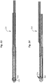
- FIGs. 2 , 4 and 6 show the distal end 14 in an inactive position.
- the blade 26 In the inactive position, the blade 26 is positioned such that its cutting edge 32 is protected within with the shaft 20 and is positioned proximally from the "open" shaft opening 24.
- the balloons 34a, 36b are also deflated.
- the blade 26 In this inactive position, the blade 26 is not exposed and does not pose and risk to the operator or the patient. Thus, the operator inserts and removes the distal end 14 into and from the carpal tunnel region when it is in the inactive position.
- FIGs. 3 , 5 and 7 show the distal end 14 in an active position.
- the blade 26 In the active position, the blade 26 is positioned such that its cutting edge 32 is within the shaft opening 24. In the active position, the blade 26 is exposed and is able to cut the transverse carpal ligament.
- the balloons 34a, 34b are also inflated to anchor the distal end 14 in position within the body and to expand the "safe zone" while the blade 26 performs cutting.
- an operator inserts the distal end in an inactive position into the carpal tunnel region so that the transverse carpal ligament is positioned within the shaft opening 24 and the tip 22 is hooked around a distal end of the transverse carpal ligament.
- the operator then activates a control to cause the balloons 34a, 34b to inflate.
- the inflated balloons 34a, 34b stabilize the distal end 14 in position within the carpal tunnel region and expand the "safe zone.”
- the operator activates a control to cause the blade 26 to move forward distally along the guideway 28 so that its cutting edge 32 moves toward the blade stop 30.
- the cutting edge 32 cuts the transverse carpal ligament that is positioned within the shaft opening 24.
- the blade stop 30 stops the cutting edge 32 from moving any further distally. Once the cutting edge 32 engages the blade stop 30, the ligament is completely cut. The operator can then repeat this process as necessary.
- the operator then activates a control to cause the balloons 34a, 34b to deflate.
- the distal end 14 resumes an inactive position and the operator can then safely remove the distal end 14 from the body.
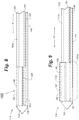
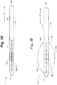
- FIGs. 8-13 illustrate views of a transverse carpal ligament cutting device 100 according to another embodiment.
- the device 100 has a proximal end (not shown) and a distal end 114 that inserts into the carpal tunnel region.
- the proximal end includes a single-hand handpiece according to any desired configuration.
- the single-hand handpiece 16 has a configuration that allows an operator to operate the device 100 using a single hand only. Skilled artisans will understand that the handpiece can have any of the embodiments described herein for a handpiece, including the handpiece shown in each of FIGs. 1 , 14 , 28 and 29 .
- the proximal end is coupled to a shaft 120 that extends distally towards a distal end 114.
- the shaft 120 can have any embodiment already described for shaft 20.
- the proximal end can have any desired configuration to allow an operator to control various functions on the distal end 114.
- the distal end 114 includes a shaft 120, a tip 122, a shaft opening 124, a blade 126, an optional blade base plate 128, a blade elevator balloon 130, a first lateral balloon 134a, a second lateral balloon 134b, a dorsal balloon 136 and a plurality of suction holes 138. Each of these components work together to safely cut a transverse carpal ligament in a carpal tunnel region.
- the distal end 114 includes a tip 122.
- the tip 122 is the distal-most end of the device 100 and is positioned distally to the shaft 120. In some cases, the tip 122 is an extension of the shaft 120. In other cases, the tip 122 is a separate piece that is positioned on the distal end 114 of the shaft 120.
- the tip 122 can have any size or shape that guides the distal end 114 through the carpal tunnel area. In this second embodiment, the tip 122 has a conical configuration. Again, skilled artisans will understand that the tip 122 can have any other desired configuration.
- the tip 122 is an echogenic tip that includes an ultrasound probe and is sized and shaped to house an ultrasound probe.
- the shaft 120 also includes a shaft opening 124.
- the shaft opening 124 also extends for a distance longitudinally along the "x" axis.
- the shaft opening 124 extends along a surface that is destined to be positioned in direct contact with the transverse carpal ligament.
- the top surface 140 is the surface that is destined to be positioned in direct contact with the transverse carpal ligament.
- the shaft opening 124 extends along the top surface 140 only so that the shaft opening 124 is only open superiorly. This results in a "closed" shaft opening 124.
- the shaft 120 also houses a blade 126.
- the blade 126 includes a cutting edge 132 that is configured to cut a carpal tunnel ligament.
- the cutting edge 132 is a top edge of the blade 126.
- the cutting edge 132 can have any desired configuration that cuts soft tissue.
- the cutting edge 132 has a sharp straight edge.
- the cutting edge 132 can also have any desired length.
- the shaft 120 also includes an optional blade base plate 128 that supports the blade 126.
- the blade base plate 128 attaches to the blade 126 along a bottom edge of the blade.
- a blade elevator balloon 130 is positioned beneath the blade base plate 128.
- the blade 126 is connected directly to the blade elevator balloon 130 (and there is no blade base plate 128).
- the blade elevator balloon 130 can have any desired configuration, such as a spherical or bilobular configuration.
- the blade elevator balloon 130 When the blade elevator balloon 130 inflates, it expands upward, thus moving the blade base plate 128 (if included) and the blade 126 upward.
- the top cutting edge 132 moves upward through the opening 124 and cuts the overlying transverse carpal ligament.
- the blade elevator balloon 130 deflates it shrinks downward, thus moving the blade base plate 128 (if included) and the blade 126 downward until it is again protected within the shaft 120.
- the blade elevator balloon 130 can have any desired configuration and size so that it can move the base plate 128 and/or the blade elevator balloon 130 upward and downward.
- the shaft 120 also includes a conduit 152 that delivers and removes gas or fluid to and from the blade elevator balloon 130.
- conduit 152 that delivers and removes gas or fluid to and from the blade elevator balloon 130.
- the blade 126 can be elevated to any desired degree.
- the degree of elevation also determines the degree of cutting of the overlying transverse carpal ligament.
- An operator can vary and individualize the degree of cutting of the transverse carpal ligament by varying the degrees of the balloon elevator 130 expansion and thus the base plate 128 elevation.
- the distal end 114 also includes a first lateral balloon 134a and a second lateral balloon 134b.
- the distal end 114 also includes a dorsal balloon 136.
- the balloons 134a, 134b, 136 inflate and expand outward laterally from the device 100.
- the balloons 134a, 134b, 136 deflate and shrink inwardly toward the device 100.
- the balloons 134a, 134b, 136 When inflated, the balloons 134a, 134b, 136 have a spherical, oval, bilobular or other configuration.
- the balloons 134a, 134b, 136 are generally flush with the distal end 114.
- This embodiment illustrates two lateral balloons and one dorsal balloon.
- skilled artisans will understand that any number of balloons can be used and the balloons can be placed anywhere about the shaft to secure the distal end 114 in position within the carpal tunnel region and to expand the "safe zone.”
- the balloons 134a, 134b, 136 also inflate to a desired size selected to accommodate the size of a patient's wrist (and thus the patient's carpal tunnel region).
- the balloons 134a, 134b, 136 can be provided with a specific size such that when they are fully inflated, they have a specific inflated size.
- each of the balloons 134a, 134b, 136 inflate to a similar or same diameter (e.g., a diameter of about 1.5mm). In patients with larger wrists, larger balloons can be used. In patients with smaller wrists, smaller balloons can be used.
- one of the balloons134a, 134b, 136 inflates to one size and another inflates to a different size.
- the balloons 134a, 134b, 136 can have a standard size but can be partially inflated or fully inflated to have a variety of different inflated sizes.
- the balloon inflation can be graded to allow the operator to choose a particular balloon diameter.
- the balloon inflation can be pressure dependent, such that the balloon manually or automatically inflates until a specific pressure is exerted on the balloon surface.
- the shaft 120 also includes a conduit 150 that delivers and removes gas or fluid from the balloons 134a, 134b, 136.
- An inflation device (not shown) supplies inflation material such as gas, fluid, water or air to the conduit 150. The inflation device also retracts inflation material from the balloons 134a, 134b, 136 back through the conduit 150 and back into the inflation device.
- a separate conduit can connect each balloon to an inflation device.
- each of the balloons 134a, 134b, 136 would be connected to an inflation device via its own conduit.
- the shaft 120 further includes a plurality of suction openings 138.
- the suction openings 138 can be provided along a shaft surface that is destined to be positioned in direct contact with the transverse carpal ligament.
- the top surface 140 is the surface that is destined to be positioned in direct contact with the transverse carpal ligament. As such, the suction openings138 can be provided along the top surface 140.
- the suction openings 138 can have any desired configuration.
- the suction openings 138 are circular holes.
- the suction openings 138 can have any other desired shapes such as a plurality of slots or a single slot.
- Suction is applied to the suction openings 138 to suck air through the suction openings 138. This causes the transverse carpal ligament to move closer to the top surface 140. Suction can be applied to the suction openings 138 using any desired mechanism.
- the shaft 120 includes a vacuum conduit 154 that sucks air through the suction openings 138.
- one or more conduits can be operably coupled to the suction openings to apply suction to the suction openings 138.
- a single conduit is used to apply suction to the suction openings 138.
- a plurality of conduits can be used.
- a first conduit can apply suction to some of the suction openings 138 and a second conduit can apply suction to other of the suction openings 138.
- any arrangement of conduits can be used.
- FIGs. 8 , 10 and 12 show the distal end 114 in an inactive position.
- the blade 126 In the inactive position, the blade 126 is positioned such that its cutting edge 132 is protected within with the shaft 120.
- the balloons 130, 134a, 134b, 136 are also deflated.
- the blade 126 In this inactive position, the blade 126 is not exposed and does not pose and risk to the operator or the patient. Thus, the operator inserts and removes the distal end 114 into and from the carpal tunnel region when it is in the inactive position.
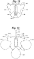
- FIGs. 9 , 11 and 13 show the distal end 114 in an active position.
- blade elevator balloon 130 is inflated and the blade 126 is positioned such that its top cutting edge 132 extends through the superior shaft opening 124 and is exposed.
- the blade 126 is exposed and is able to cut the transverse carpal ligament.
- the balloons 134a, 134b, 136 are also inflated to anchor the distal end 114 in position within the body and to expand the patient's safe zone while the blade 126 performs cutting.
- the operator next activates a control to cause the balloon elevator to expand so that the cutting edge 132 moves upward through the opening 124 and cuts into the transverse carpal ligament.
- the depth of the cut can be varied by modulating the extent of the blade elevator balloon 130 inflation. In general, 2-3 mm of upward displacement is sufficient to cut the transverse carpal ligament.
- the ligament may be completely cut by the upward motion, or may be partially cut/fenestrated by reducing the amount of blade elevation and/or using a blade having a serrated or saw tooth cutting edge 132.
- the operator can manually move the entire device 100 forward distally and backward proximally to impart a sawing motion, as necessary or desired.
- the amplitude of anticipated operator motion should be small given the stabilizing properties of the device.
- the operator activates controls to stop the suction through the suction holes and to deflate all the balloons 134a, 134b, 136. This causes the blade 126 to move back downward into the shaft 120. The operator then safely removes the distal end 114 from the body.
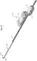
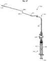
- FIGs. 14-27 illustrate views of a transverse carpal ligament cutting device 200 according to another embodiment.
- the device 200 has a proximal end 212 and a distal end 214.
- the proximal end 212 includes a handle 216.
- the distal end 214 includes a shaft 220 that inserts into the carpal tunnel region.
- the handle 216 includes a blade activation assembly 222.
- the device 200 also includes an inflation assembly 218 coupled to the handle 216.
- the inflation assembly 218 and blade activation assembly 222 each control various functions of the shaft 220 at the distal end 214.
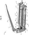
- the distal end 214 includes a shaft 220, a tip 224, a shaft opening 226, a blade 228, a first balloon 234a and a second balloon 234b.
- the shaft 220 can also include a shaft cover 236.
- the shaft 220 also has a size and cross-section shape that is suitable for being inserted into the carpal tunnel region.
- the shaft 220 extends longitudinally along a longitudinal axis "x.”
- the shaft 220 has a top surface 238, side surfaces 240a, 240b, and a bottom surface 242.
- the shaft 220 can also have any embodiment described for shaft 20 or shaft 120.
- the distal end 214 includes a tip 224.
- the tip 224 is the distal-most end of the device 200 and is positioned distally to the shaft 220. In some cases, the tip 224 is an extension of the shaft 220. In other cases, the tip 224 is a separate piece that is positioned on the distal end of the shaft 220.
- the tip 224 can have any size or shape that guides the distal end 214 through the carpal tunnel area. In this embodiment, the tip 224 has a rounded configuration. Of course, the tip 224 can have any other desired configuration.
- the tip 224 is an echogenic tip that includes an ultrasound probe and is sized and shaped to house an ultrasound probe.
- the shaft 220 also includes a shaft opening 226.
- the shaft opening 226 also extends for a distance longitudinally along the surface that is destined to be positioned adjacent to or in direct contact with the transverse carpal tunnel ligament. In this embodiment, as shown in FIGs. 15-16 , the shaft opening 226 extends along the top surface 238 so that the shaft opening 226 is open superiorly.
- the shaft 220 also houses a blade 228.
- the blade 228 includes a blade shaft 244 and a blade working end 246.
- the blade shaft 244 engages with a blade activation assembly 222 to move the blade 228 forward and backward.
- the blade working end 246 is the end that is configured to cut a transverse carpal ligament.
- the blade working end 246 also includes a blade pin 256.
- the blade pin 256 is positioned on the blade working end 246 such that the pin 256 moves along a blade guideway 258 (described below).
- the blade pin 256 is positioned along the outer surface 248.
- the blade pin 256 can be mechanically or weldedly attached to the blade working end 246.
- the blade pin 256 is provided as part of or integral to the blade working end 246 and is not a separate piece.
- the cutting edge 254 of the blade 228 is housed within the shaft 220 and is not exposed through the shaft opening 226.
- the cutting edge 254 is housed within the shaft 220 and is not exposed through the shaft opening 226.
- the device 200 is in an inactive or protected position.
- the blade pin 256 when the blade pin 256 is positioned along the plateau 264, as shown in FIGs. 24-25 , the cutting edge 254 of the blade 228 extends through the shaft opening 226 and is exposed. In this case, the device 200 is in an active position and is able to cut soft tissue.
- the shaft 220 also includes one or more balloons that expand radially outwardly from the shaft 220.
- the balloons can be positioned anywhere about the shaft 220 such that they expand the safe zone of the carpal tunnel region.
- This embodiment illustrates two lateral balloons 234a, 234b that are positioned on sides 240a, 240b of the shaft 220.
- the balloons 234a, 234b inflate and expand outward laterally from the shaft 220.
- the balloons 234a, 234b deflate and shrink inwardly toward the shaft 220.
- the balloons 234a, 234b When inflated, the balloons 234a, 234b have a spherical, oval, bilobular or other configuration. When deflated, the balloons 234a, 234b can be generally flush with the shaft 220.
- the shaft 220 also optionally includes a first channel 230a and a second channel 230b.
- the first lateral balloon 234a can be positioned so that it lies within the first channel 230a.
- the second lateral balloon 234b can be positioned so that it lies within the second channel 230b.
- the channels 230a, 230b can have any size and shape that accommodates the balloons 234a, 234b.
- any number of radially expanding balloons can be used and be placed anywhere about the shaft 220 to secure the distal end 214 in position within the carpal tunnel region and to expand the "safe zone.” As the radially expanding balloons inflate, they move the flexor tendons, median nerve, and ulnar neurovascular bundle away from the device 200, effectively increasing the "safe zone.” This helps to ensure that only the transverse carpal ligament is cut and that nearby at-risk structures are not cut.
- the device 200 also includes a blade activation assembly 222.
- FIGs. 17-19 illustrate an embodiment of a blade activation assembly 222.
- the blade activation assembly 222 includes a slider button 270, a first plate 272, a second plate 274, a plate pin 276, a first screw 278a, a second screw 278b, a blade latch 280, a blade latch pin 282 and a ball 284.
- the slider button 270 is positioned on an external surface of the handle 216. An operator engages the slider button 270 with a finger (for example by engaging a thumb with the slider button 270).
- the first conduit 286a connects the first balloon 234a to the inflation device 288.
- the second conduit 286b connects the second balloon 234b to the inflation device 288.
- the inflation device 288 supplies inflation material such as gas, fluid, water or air to each of the first conduit 286a and second conduit 286b, which in turn supply the inflation material to the first balloon 234a and the second balloon 234b.
- the inflation material causes the first balloon 234a and the second balloon 234b to inflate.
- the inflation device 288 also retracts inflation material from the first balloon 234a and second balloon 234b back through the first conduit 286a and second conduit 286b and back into the inflation device 288.
- the inflation device 288 inflates and deflates the balloons 234a, 234b.
- the coupling 292 can combine inflation material from the first conduit 286a and the second conduit 286b into a single conduit 294 when the material is moving back towards the inflation device 288.
- Such a piping arrangement 290 can provide increased efficiency of movement of the inflation material.
- FIG. 15 illustrates one embodiment showing a conduit positioned inside of a balloon.
- the second conduit 286b is shown positioned inside of the second balloon 234b.
- the second conduit 286b includes a plurality of openings 202 that open into the inside of the second balloon 234b. Inflation material moves in and out of these openings 202.
- the first balloon 234a can connect to the first conduit 286a in a similar or identical manner.
- the balloons 234a, 234b can have any desired configuration that allows them to inflate and deflate.
- the entire balloon is expandable and thus inflates and deflates.
- only part of the balloon is expandable.
- the balloon can have a fixed portion and an expandable portion.
- FIG. 16 illustrates an embodiment wherein the balloon 234b has a fixed portion and an expandable portion 206.
- the fixed portion 204 can be the portion that directly attaches to conduit 286b whereas the expandable portion 206 does not directly attach to the conduit 286b and instead expands freely of the conduit 286b.
- the balloons 234a, 234b also inflate to a desired size selected to accommodate the size of a patient's wrist (and thus the patient's carpal tunnel region).
- the balloons 234a, 234b can be provided with a specific size such that when they are fully inflated, they have a specific inflated size.
- each of the balloons 234a, 234b inflate to a similar or same diameter (e.g., a diameter of about 1.5mm). In patients with larger wrists, larger balloons can be used. In patients with smaller wrists, smaller balloons can be used.
- one of the balloons 234a, 234b inflates to one size and another inflates to a different size.
- the balloons 234a, 234b can have a standard size but can be partially inflated or fully inflated to have a variety of different inflated sizes.
- the balloon inflation can be graded to allow the operator to choose a particular balloon diameter.
- the balloon inflation can be pressure dependent, such that the balloon manually or automatically inflates until a specific pressure is exerted on the balloon surface.
- the inflation device 288 can be any desired device known in the art that holds inflation material and both pushes inflation material out of the inflation device 288 and pulls inflation material back into the inflation device 288.
- the inflation device 288 is a syringe 232.
- Skilled artisans will understand that the illustrated syringe 232 is merely one embodiment of an inflation device 288 and that other devices are suitable.
- the syringe 232 is provided outside of the handle 216.
- skilled artisans will understand that the syringe 232 can instead be provided inside of the handle 216.
- the syringe 232 can be provided by itself or as part of a syringe control assembly (e.g., as a part of a syringe control assembly 324 described with reference to FIGs. 28-32 ).
- the syringe 232 includes a barrel 296 and a plunger 298.
- the syringe 232 holds fluid inside of the barrel 296.
- the plunger 298 When the operator desires to inflate the balloons 234a, 234b, he or she pushes the plunger 298 to push fluid into the piping arrangement 290 (or directly into the conduits 286a, 286b). The fluid moves into the conduits 286a, 286b and exits through the openings 202 into the balloons 234a, 234b.
- the operator desires to deflate the balloons 234a, 234b, he or she pulls or retracts the plunger 298 to pull fluid back towards the inflation device 288. This causes fluid to move out of the balloons 234a, 234b through the openings 202 and back into the conduits 286a, 286b.
- an operator first obtains a device 200 that is in the first inactive position.
- the device 200 In the first inactive position, the device 200 has its blade 228 positioned such that the blade pin 256 is positioned at the distal guideway end 260 of the blade guideway 258 as shown in FIG. 23 .
- the cutting edge 254 is fully housed and protected within the shaft 220 and the device 200 can be safely inserted into a carpal tunnel region.
- the device 200 also has its balloons 234a, 234b in a deflated configuration.
- the operator inserts the distal end 214 into a carpal tunnel region such that the transverse carpal ligament is positioned adjacent the top surface 238 of the shaft 220.
- the operator then activates a control to cause the balloons 234a, 234b to inflate and to expand the safe zone within the carpal tunnel region.
- the operator next moves the slider button 270 backward to move the blade working end backward and up the distal incline 262 as shown in FIG. 24 .
- the cutting edge 254 is fully exposed and able to cut the transverse carpal ligament.
- the operator continues to move the slider button 270 backward to move the blade working end (and cutting edge) backward along the plateau 264. As the cutting edge 254 moves backward, it cuts the transverse carpal ligament.
- the operator continues to move the slider button 270 backward to move the blade working end backward and down the proximal incline 266.
- the blade 228 stops moving backward once the blade pin 256 reaches the proximal guideway end 268 as shown in Figure 26 .
- the transverse carpal ligament is cut and the device 200 is in the second inactive position.
- the operator then activates a control to cause the balloons 234a, 234b to deflate.
- the device 200 has its blade 228 positioned such that the blade pin 256 is positioned at the proximal guideway end 268 of the blade guideway 258 as shown in FIG. 26 .
- the cutting edge 254 is fully housed and protected within the shaft 220 and the device 200 can be safely removed from the body.
- the handle also houses the syringe.
- the syringe includes an actuator or control positioned outside of the handle that controls functions of the syringe.
- the control can be a lever, slider button, push button and/or clamp.
- the control is another slider button positioned on an external surface of the handle.
- the slider button can be coupled to a plungerto control movement of the plunger.
- the slider button is directly connected to the plunger.
- the control is a clamp. In such cases, the clamp can be coupled to a plunger to control movement of the plunger.
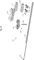
- FIGs. 28-32 illustrate views of a transverse carpal ligament cutting device 300 according to another embodiment.
- the device 300 has a proximal end 312 and a distal end 314.
- the proximal end 312 includes a handle 316.
- the distal end 314 includes a shaft that inserts into the carpal tunnel region.
- the handle 316 includes a blade activation assembly 322.
- the device 300 also includes an inflation assembly 318 coupled to the handle 316.
- the inflation assembly 318 and blade activation assembly 322 each control various functions of the shaft at the distal end 314.
- the device 300 also includes an inflation assembly 318.
- the inflation assembly 318 includes one or more or all of the components and functions already described for the inflation assembly 218.
- the inflation assembly 318 is shown as including at least the first balloon 234a, a first conduit 286a, the second balloon 234b and a second conduit 286b.
- the barrel 334 also includes a flange 338.
- the flange 338 at least partially expands radially outward from the barrel 334.
- the flange 338 expands radially outwardly on a first side and a second side such that there is a first flange portion 338a on the first side and a second flange portion 338b on the second side.
- the syringe control assembly 324 includes a decompression mechanism 330.
- the clamp 326 is operably coupled to the decompression mechanism 330 such that when the clamp 326 is engaged, the decompression mechanism 330 causes the barrel 334 to move backward proximally with respect to the plunger 336. This causes the plunger 336 to move deeper into the barrel 334, thus pushing fluid in the barrel 334 out of the syringe 328 and into the balloon conduits.
- the decompression mechanism 330 is operably coupled to a barrel holder 340 to move the first flange portion 338a and/or the second flange portion 338b forward distally and backward proximally.
- the syringe control assembly 324 also includes a compression mechanism 332.
- the clamp 326 is operably connected to the compression mechanism 332 such that when the clamp 326 is reengaged, the compression mechanism 332 causes the barrel to move forward distally with respect to the plunger 336. This causes the plunger 336 to move out of the barrel 334 such that it pulls fluid out of the balloon conduits and back into the barrel 334.
- the compression mechanism 332 is operably coupled to a barrel plate 392 to move the first flange portion 338a and/or the second flange portion 338b forward distally and backward proximally.
- the barrel holder 340 connects to the barrel 334.
- the barrel holder 340 connects to the second flange portion 338b.
- the barrel holder 340 includes a groove 342 that retains the second flange portion 338b.
- the barrel holder 340 holds and moves the second flange portion 338b forward distally and resists movement backward proximally (thus moving the barrel 334 forward distally and resisting movement of the barrel 334 backward proximally).
- the barrel plate 392 also connects to the barrel 334. In some cases, the barrel plate 392 connects to the first flange portion 338a. In some cases, the barrel plate 392 includes a groove 394 that receives the first flange portion 338a. The barrel plate 392 holds and moves the first flange portion 338a backward proximally (thus moving the barrel 334 backward proximally).
- An operator first compresses or clamps the hand-engaging portion 350 of the clamp 326, causing the arm-connecting portion 352 to move proximally via a pivot point within the arm-connecting portion 352 (not shown), which in turn pulls the arm 354 proximally.
- the arm 354 moves proximally it acts on a lower portion of the connector 356 to move the lower portion proximally via a pivot point within the connector 356 (not shown).
- As the lower portion moves proximally it causes the upper portion to move distally.
- the distal movement of the upper portion acts on the compression mechanism 332.
- the barrel plate 392 pushes the first flange portion 338a proximally, thereby compressing the syringe 328.
- the decompression mechanism 330 is also connected to the second flange portion 338b via the barrel holder 340. The decompression mechanism 330 resists compression of the syringe 328 via the spring 372.
- an operator first obtains a device 300 that is in a first inactive position.
- the device 300 In the first inactive position, the device 300 has its blade 228 positioned such that the blade cutting edge is protected within a shaft and the device 300 can be safely inserted into a carpal tunnel region.
- the device 300 also has its balloons in a deflated configuration.
- the inactive position can be any inactive position of the devices already described herein.
- the operator inserts the distal end 314 into a carpal tunnel region and then engages the clamp 326, thus prompting the syringe control assembly 334 and causing the balloons to inflate and to expand the safe zone within the carpal tunnel region.
- the operator Once cutting is completed, the operator reengages the clamp 326, thus prompting the syringe control assembly 324 to cause the balloons to deflate.
- the soft tissue cutting device also includes a safety mechanism.
- a safety mechanism can be provided in any of the embodiments already described.
- the safety mechanism prevents an operator from operating the device to deflate the balloons while the blade is active.
- the device has a locked position and an unlocked position. In the locked position, the balloons cannot be deflated. In the unlocked position, the balloons can be inflated.
- the method can use any of the soft issue cutting devices described herein.
- the method includes steps of providing a soft-tissue cutting device comprising: (a) a shaft, (b) a shaft opening in the shaft, (c) a blade that extends through and withdraws from the shaft opening, and (d) one or more balloons coupled to the shaft that expand radially outward from the shaft.
- the method can further include steps of advancing the soft-tissue cutting device to a body region, expanding the one or more balloons radially outward and extending the blade through the shaft opening to cut the soft tissue.
- the method includes the steps of providing a cutting device having an inactive position and an active position, wherein in the inactive position the device includes an unexposed blade and one or more deflated balloons and in the active position the device includes an exposed blade and one or more inflated radially-expanding balloons, advancing the device to a carpal tunnel region while the device is in the inactive position, and cutting a transverse carpal ligament while the device is in the active position.
Claims (13)
- Vorrichtung zum Schneiden des transversalen Karpalbandes (200), umfassend:(a) einen Schaft (220) mit einer oberen Fläche (238), zwei Seitenflächen (240a, 240b) und einer unteren Fläche (242);(b) eine Schaftöffnung (226), die sich über eine Strecke entlang der oberen Fläche (238) erstreckt;(c) eine Klinge (228) mit einem Klingenarbeitsende (246), wobei das Klingenarbeitsende (246) eine Schneidkante (254) aufweist, die dem proximalen Ende (212) der Vorrichtung (200) zugewandt ist;(d) eine Klingenführungsbahn (258) innerhalb des Schafts (220), wobei sich das Klingenarbeitsende (246) entlang der Klingenführungsbahn (258) bewegt, wobei die Klingenführungsbahn (258) ein distales Führungsbahnende (260), eine distale Neigung (262) und ein Plateau (264) aufweist, eine proximale Neigung (266) und ein proximales Führungsbahnende (268), wobei das Klingenarbeitsende (246) so konfiguriert ist, dass es sich auf der distalen Neigung (262) nach oben, entlang des Plateaus (264) nach hinten und entlang der proximalen Neigung (266) nach unten bewegt; und,(e) einen oder mehrere Ballons (234a, 234b), die mit dem Schaft (220) gekoppelt sind und sich vom Schaft (220) radial nach außen ausdehnen.
- Vorrichtung (200) zum Schneiden des transversalen Karpalbandes nach Anspruch 1, wobei das Klingenarbeitsende (246) als Haken konfiguriert ist, wobei der Haken die Schneidkante (254) aufweist, die dem proximalen Ende der Vorrichtung (200) zugewandt ist.
- Vorrichtung zum Schneiden des transversalen Karpalbandes (200) nach Anspruch 1 oder 2, wobei das Klingenarbeitsende (246) einen Klingenbolzen (256) aufweist, wobei sich der Klingenbolzen (256) innerhalb der Klingenführungsbahn (258) bewegt.
- Vorrichtung (200) zum Schneiden des transversalen Karpalbandes nach einem der vorstehenden Ansprüche, wobei das Plateau (264) zwischen der distalen Neigung (262) und der proximalen Neigung (266), die distale Neigung (262) zwischen dem distalen Führungsbahnende (260) und dem Plateau (264), und die proximale Neigung (266) zwischen dem proximalen Führungsbahnende (268) und dem Plateau (264) positioniert ist.
- Vorrichtung (200) zum Schneiden des transversalen Karpalbandes nach Anspruch 4, wobei das Klingenarbeitsende (246) am distalen Führungsbahnende (260) positioniert ist und die Schneidkante (254) im Schaft (220) untergebracht ist.
- Vorrichtung zum Schneiden des transversalen Karpalbandes nach Anspruch 4 oder 5, wobei, wenn das Klingenarbeitsende (246) entlang des Plateaus (264) positioniert ist, sich das Klingenarbeitsende (246) durch die Schaftöffnung (226) erstreckt, sodass die Schneidkante (254) freiliegt.
- Vorrichtung zum Schneiden des transversalen Karpalbandes nach einem der Ansprüche 4 bis 6, wobei, wenn das Klingenarbeitsende (246) am proximalen Führungsbahnende (268) positioniert ist, die Schneidkante (254) im Schaft (220) untergebracht ist.
- Vorrichtung zum Schneiden des transversalen Karpalbandes nach einem der vorstehenden Ansprüche, wobei der eine oder die mehreren Ballons (234a, 234b) einen seitlichen Ballon (234a, 234b) umfassen, der sich von einer der beiden Seitenflächen (240a, 240b) radial nach außen ausdehnt.
- Vorrichtung zum Durchtrennen des transversalen Karpalbandes nach einem der vorhergehenden Ansprüche, ferner umfassend einen Sicherheitsmechanismus, wobei der Sicherheitsmechanismus so konfiguriert ist, dass er die Vorrichtung (200) in eine verriegelte Position bringt, um zu verhindern, dass der eine oder die mehreren Ballons (234a, 234b) entleert werden, wenn sich die Vorrichtung (200) in der aktiven Position befindet, und wobei der Sicherheitsmechanismus so konfiguriert ist, dass er die Vorrichtung (200) in eine entriegelte Position bringt, damit die Ballons (234a, 234b) aufgeblasen oder entleert werden können, wenn sich die Vorrichtung (200) in der inaktiven Position befindet.
- Vorrichtung (200) zum Schneiden des transversalen Karpalbandes nach einem der vorstehenden Ansprüche, ferner umfassend eine Spritze (232), die ein Aufblasmaterial hält, und eine Leitung (286a, 286b), wobei die Spritze (232) einen Zylinder (296) und einen Kolben (298) umfasst, wobei die Leitung (286a, 286b) den einen oder die mehreren Ballons (234a, 234b) mit der Spritze (232) verbindet, wobei die Spritze (232) das Aufblasmaterial vorwärts aus der Spritze (232) heraus, in die Leitung (286a, 286b) und in den einen oder die mehreren Ballons (234a, 234b) bewegt, um den einen oder die mehreren Ballons (234a, 234b) aufzublasen, und wobei die Spritze (232) das Aufblasmaterial von dem einen oder den mehreren Ballons (234a, 234b) nach hinten, in die Leitung (286a, 286b) und in die Spritze (232) bewegt, um den einen oder die mehreren Ballons (234a, 234b) zu entleeren.
- Vorrichtung (200) zum Schneiden des transversalen Karpalbandes nach Anspruch 10, ferner umfassend einen Aktivator (146), der mit einer Spritzensteuereinheit (324) gekoppelt ist, wobei die Spritzensteuereinheit (324) die Bewegung des Zylinders (296) der Spritze (232) relativ zum Kolben (298) der Spritze (232) steuert, wobei der Aktivator (146) so konfiguriert ist, dass er die Spritzensteueranordnung (324) veranlasst, den Kolben (298) in den Zylinder (296) zu bewegen, um das Aufblasmaterial bei Aktivierung durch einen Benutzer aus dem Zylinder (296) herauszubewegen.
- Vorrichtung (200) zum Schneiden des transversalen Karpalbandes nach Anspruch 11, wobei der Aktivator (146) so konfiguriert ist, dass er bewirkt, dass die Spritzensteuereinheit (324) den Kolben (298) aus dem Zylinder (296) herausbewegt, um das Aufblasmaterial bei Aktivierung durch den Benutzer zurück in den Zylinder (296) zu bewegen.
- Vorrichtung (200) zum Schneiden des transversalen Karpalbandes nach einem der vorhergehenden Ansprüche, wobei die Schneidkante innerhalb des Schaftes untergebracht ist und wobei ein oder mehrere Ballons aufgeblasen werden, wenn sich die Vorrichtung in einer inaktiven Position befindet, und wobei sich die Schneidkante durch die Schaftöffnung erstreckt und wobei der eine oder die mehreren Ballons aufgeblasen werden, wenn sich die Vorrichtung in einer aktiven Position befindet.
Priority Applications (1)
| Application Number | Priority Date | Filing Date | Title |
|---|---|---|---|
| EP20176487.5A EP3766440A1 (de) | 2014-09-18 | 2015-09-11 | Weichgewebeschneidegerät |
Applications Claiming Priority (4)
| Application Number | Priority Date | Filing Date | Title |
|---|---|---|---|
| US201462052208P | 2014-09-18 | 2014-09-18 | |
| US201562167543P | 2015-05-28 | 2015-05-28 | |
| US201562192770P | 2015-07-15 | 2015-07-15 | |
| PCT/US2015/049558 WO2016044072A1 (en) | 2014-09-18 | 2015-09-11 | Soft tissue cutting device and methods of use |
Related Child Applications (2)
| Application Number | Title | Priority Date | Filing Date |
|---|---|---|---|
| EP20176487.5A Division-Into EP3766440A1 (de) | 2014-09-18 | 2015-09-11 | Weichgewebeschneidegerät |
| EP20176487.5A Division EP3766440A1 (de) | 2014-09-18 | 2015-09-11 | Weichgewebeschneidegerät |
Publications (2)
| Publication Number | Publication Date |
|---|---|
| EP3193748A1 EP3193748A1 (de) | 2017-07-26 |
| EP3193748B1 true EP3193748B1 (de) | 2020-07-01 |
Family
ID=54150737
Family Applications (2)
| Application Number | Title | Priority Date | Filing Date |
|---|---|---|---|
| EP15767038.1A Active EP3193748B1 (de) | 2014-09-18 | 2015-09-11 | Weichgewebeschneidegerät |
| EP20176487.5A Pending EP3766440A1 (de) | 2014-09-18 | 2015-09-11 | Weichgewebeschneidegerät |
Family Applications After (1)
| Application Number | Title | Priority Date | Filing Date |
|---|---|---|---|
| EP20176487.5A Pending EP3766440A1 (de) | 2014-09-18 | 2015-09-11 | Weichgewebeschneidegerät |
Country Status (3)
| Country | Link |
|---|---|
| US (6) | US10357272B2 (de) |
| EP (2) | EP3193748B1 (de) |
| WO (1) | WO2016044072A1 (de) |
Cited By (1)
| Publication number | Priority date | Publication date | Assignee | Title |
|---|---|---|---|---|
| EP3771445B1 (de) * | 2019-07-31 | 2024-03-06 | Pajunk GmbH Medizintechnologie | Chirurgisches instrument |
Families Citing this family (16)
| Publication number | Priority date | Publication date | Assignee | Title |
|---|---|---|---|---|
| WO2014165130A2 (en) * | 2013-03-13 | 2014-10-09 | Boston Scientific Scimed, Inc. | Devices for tissue separation and related methods of use |
| US9962181B2 (en) | 2014-09-02 | 2018-05-08 | Tenex Health, Inc. | Subcutaneous wound debridement |
| EP3193748B1 (de) | 2014-09-18 | 2020-07-01 | Mayo Foundation for Medical Education and Research | Weichgewebeschneidegerät |
| JP6815998B2 (ja) | 2014-12-03 | 2021-01-20 | パブメド インク. | 繊維構造の経皮分裂のためのシステム及び方法 |
| US11253285B2 (en) | 2016-04-04 | 2022-02-22 | University Of Utah Research Foundation | Subcutaneous cutting device |
| CN110891502A (zh) * | 2017-07-22 | 2020-03-17 | 海德·里达 | 一种扁桃体切除术抽吸解剖器装置 |
| US11026715B2 (en) * | 2017-09-28 | 2021-06-08 | John Mayberry | Chest cavity suction medical apparatus and method |
| US10864055B2 (en) * | 2017-10-13 | 2020-12-15 | Sonex Health, Inc. | Tray for a soft tissue cutting device and methods of use |
| ES1220270Y (es) * | 2018-06-19 | 2019-02-07 | Com Medy Health Devices S L | Bisturi para cirugia del tunel carpiano |
| CN108852468B (zh) * | 2018-07-16 | 2023-06-27 | 无锡市中医医院 | 一种新型超声刀及其使用方法 |
| EP3908215B1 (de) | 2019-01-11 | 2023-08-02 | Mayo Foundation for Medical Education and Research | Mikroinvasive chirurgische vorrichtung |
| WO2022150837A1 (en) * | 2021-01-08 | 2022-07-14 | Sonex Health, Inc. | Surgical cutting device for ultrasonic guided soft tissue surgery |
| USD989961S1 (en) | 2021-04-30 | 2023-06-20 | Sonex Health, Inc. | Soft tissue cutting device |
| CN113662632A (zh) * | 2021-08-19 | 2021-11-19 | 浙江海洋大学东海科学技术学院 | 一种多功能医疗刀 |
| IT202100032843A1 (it) | 2021-12-28 | 2023-06-28 | Paul Douglas Paterson | Strumento di taglio chirurgico |
| WO2023229943A1 (en) * | 2022-05-27 | 2023-11-30 | Edwards Lifesciences Corporation | Pericardial transection device with suction device |
Citations (1)
| Publication number | Priority date | Publication date | Assignee | Title |
|---|---|---|---|---|
| US5735865A (en) * | 1995-12-19 | 1998-04-07 | Richard Wolf Gmbh | Instrument for endoscopic therapy |
Family Cites Families (200)
| Publication number | Priority date | Publication date | Assignee | Title |
|---|---|---|---|---|
| US2123768A (en) | 1936-06-18 | 1938-07-12 | Corsico-Piccolini Hector | Safety razor blade |
| US3435826A (en) * | 1964-05-27 | 1969-04-01 | Edwards Lab Inc | Embolectomy catheter |
| US4979951A (en) * | 1984-05-30 | 1990-12-25 | Simpson John B | Atherectomy device and method |
| US5089000A (en) * | 1987-09-18 | 1992-02-18 | John M. Agee | Surgical method and instrument therefor |
| US4963147A (en) * | 1987-09-18 | 1990-10-16 | John M. Agee | Surgical instrument |
| US4962770A (en) | 1987-09-18 | 1990-10-16 | John M. Agee | Surgical method |
| US5345927A (en) | 1990-03-02 | 1994-09-13 | Bonutti Peter M | Arthroscopic retractors |
| US5197971A (en) * | 1990-03-02 | 1993-03-30 | Bonutti Peter M | Arthroscopic retractor and method of using the same |
| US5954739A (en) | 1990-03-02 | 1999-09-21 | General Surgical Innovations, Inc. | Method of dissecting tissue layers |
| US5331975A (en) | 1990-03-02 | 1994-07-26 | Bonutti Peter M | Fluid operated retractors |
| US5425355A (en) * | 1991-01-28 | 1995-06-20 | Laserscope | Energy discharging surgical probe and surgical process having distal energy application without concomitant proximal movement |
| US5125927A (en) | 1991-02-19 | 1992-06-30 | Belanger Neil F | Breakaway electrode for surgical cutting and cauterizing tool |
| US5217007A (en) | 1991-04-26 | 1993-06-08 | Cook Incorporated | Speculum for forming an ostomy in a trachea |
| ZA923086B (en) | 1991-04-29 | 1993-10-28 | South African Medical Research | A delivery system for biologicaly active growth or morphogenetic factors and a method for preparing such delivery system |
| US5865728A (en) | 1991-05-29 | 1999-02-02 | Origin Medsystems, Inc. | Method of using an endoscopic inflatable lifting apparatus to create an anatomic working space |
| US7744617B2 (en) | 1991-05-29 | 2010-06-29 | Covidien Ag | Method and inflatable chamber apparatus for separating layers of tissue |
| US6361543B1 (en) | 1991-05-29 | 2002-03-26 | Sherwood Services Ag | Inflatable devices for separating layers of tissue, and methods of using |
| US5325883A (en) * | 1991-11-04 | 1994-07-05 | Orr Terrence R | Device and method for carpal tunnel release |
| US5655545A (en) | 1992-02-06 | 1997-08-12 | Johnson; Gerald W. | Dissection of tissue by tissue expander |
| US5306284A (en) | 1992-02-19 | 1994-04-26 | John Agee | Surgical instrument |
| US6312442B1 (en) | 1992-06-02 | 2001-11-06 | General Surgical Innovations, Inc. | Method for developing an anatomic space for laparoscopic hernia repair |
| US5772680A (en) | 1992-06-02 | 1998-06-30 | General Surgical Innovations, Inc. | Apparatus and method for developing an anatomic space for laparoscopic procedures with laparoscopic visualization |
| US5540711A (en) | 1992-06-02 | 1996-07-30 | General Surgical Innovations, Inc. | Apparatus and method for developing an anatomic space for laparoscopic procedures with laparoscopic visualization |
| US6540764B1 (en) | 1992-06-02 | 2003-04-01 | General Surgical Innovations, Inc. | Apparatus and method for dissecting tissue layers |
| US5620446A (en) | 1992-07-14 | 1997-04-15 | Endoscopic Heel Systems, Inc. | Surgical apparatus for performing endoscopic surgery at locations where tissue inserts into bone |
| US5569283A (en) * | 1993-09-03 | 1996-10-29 | United States Surgical Corporation | Surgical cutting instrument with guarded blade |
| US5690664A (en) | 1993-09-13 | 1997-11-25 | United States Surgical Corporation | Trocar having movable blade |
| US5620458A (en) | 1994-03-16 | 1997-04-15 | United States Surgical Corporation | Surgical instruments useful for endoscopic spinal procedures |
| US5690668A (en) | 1994-06-29 | 1997-11-25 | General Surgical Innovations, Inc. | Extraluminal balloon dissection |
| AU699844B2 (en) | 1994-08-25 | 1998-12-17 | Ethicon Endo-Surgery, Inc. | Safety trocar |
| US5547463A (en) | 1994-10-07 | 1996-08-20 | United States Surgical Corporation | Surgical hand support apparatus |
| DE4444166C2 (de) * | 1994-12-12 | 1998-09-24 | Urotech Med Tech Gmbh | Flexible Messervorrichtung für chirurgische Zwecke |
| US5643296A (en) * | 1994-12-16 | 1997-07-01 | Devices For Vasclar Intervention | Intravascular catheter with guiding structure |
| US5649946A (en) | 1995-03-20 | 1997-07-22 | Bramlet; Dale G. | Carpal tunnel medical instrument |
| US5607441A (en) | 1995-03-24 | 1997-03-04 | Ethicon Endo-Surgery, Inc. | Surgical dissector |
| US5569300A (en) | 1995-04-12 | 1996-10-29 | Redmon; Henry A. | Dilating surgical forceps having illumination means on blade inner surface |
| US5702417A (en) | 1995-05-22 | 1997-12-30 | General Surgical Innovations, Inc. | Balloon loaded dissecting instruments |
| US7037317B2 (en) | 1995-05-22 | 2006-05-02 | United States Surgical Corporation | Balloon dissecting instruments |
| MX9601936A (es) | 1995-07-07 | 1997-01-31 | Becton Dickinson Co | Una bandeja mejorada para la preparacion de la piel para uso en procedimientos quirurgicos. |
| US6083177A (en) | 1995-09-14 | 2000-07-04 | Kobren; Myles S. | Cervical biopsy device and method |
| JP3736877B2 (ja) | 1995-09-19 | 2006-01-18 | 義治 湯本 | 腱鞘切開刀 |
| US5957944A (en) | 1995-11-07 | 1999-09-28 | Biomet, Inc. | Method for treatment of trigger finger |
| CN1211170A (zh) | 1995-11-21 | 1999-03-17 | 哈韦尔工业(私人)有限公司 | 一次性解剖刀 |
| US5709697A (en) | 1995-11-22 | 1998-01-20 | United States Surgical Corporation | Apparatus and method for removing tissue |
| US5908433A (en) | 1996-05-10 | 1999-06-01 | Stryker Corporation | Carpal tunnel knife |
| US5766198A (en) | 1996-06-10 | 1998-06-16 | Li; Bing | Surgical knife employing a vacuum to ensure precise depth of incisions |
| US5810806A (en) | 1996-08-29 | 1998-09-22 | Ethicon Endo-Surgery | Methods and devices for collection of soft tissue |
| US6117153A (en) * | 1996-10-03 | 2000-09-12 | Interventional Technologies, Inc. | Neovascularization catheter |
| US5769865A (en) * | 1997-02-25 | 1998-06-23 | Surgical Insight, Inc. | Instrument and method for transection of a ligament |
| US5800449A (en) | 1997-03-11 | 1998-09-01 | Ethicon Endo-Surgery, Inc. | Knife shield for surgical instruments |
| US5827311A (en) | 1997-05-08 | 1998-10-27 | Biomet Inc | Carpal tunnel tome |
| US6015421A (en) | 1997-05-15 | 2000-01-18 | General Surgical Innovations, Inc. | Apparatus and method for developing an anatomic space for laparoscopic procedures |
| FR2764515B1 (fr) * | 1997-06-16 | 1999-09-03 | Sedat | Dispositif de gonflage de ballonnets |
| NL1006944C2 (nl) | 1997-09-04 | 1999-03-11 | Mark Hans Emanuel | Chirurgische endoscopische snij-inrichting. |
| US5904699A (en) | 1997-09-19 | 1999-05-18 | Ethicon Endo-Surgery, Inc. | Trocar for penetration and skin incision |
| US6017356A (en) | 1997-09-19 | 2000-01-25 | Ethicon Endo-Surgery Inc. | Method for using a trocar for penetration and skin incision |
| US6012586A (en) | 1997-11-24 | 2000-01-11 | Maxxim Medical, Inc. | Medical procedure kit |
| US6758848B2 (en) | 1998-03-03 | 2004-07-06 | Senorx, Inc. | Apparatus and method for accessing a body site |
| US6875182B2 (en) * | 1998-03-03 | 2005-04-05 | Senorx, Inc. | Electrosurgical specimen-collection system |
| US6030402A (en) | 1998-04-23 | 2000-02-29 | Thompson; Ronald J. | Apparatus and methods for the penetration of tissue, and the creation of an opening therein |
| US5968061A (en) | 1998-04-27 | 1999-10-19 | Theodor Esser | Endoscopic surgical instrument for the implementation of endoscopic surgical procedures |
| US7540875B2 (en) | 1998-06-01 | 2009-06-02 | Avatar Design & Development, Inc. | Surgical cutting tool with automatically retractable blade assembly |
| US6402770B1 (en) | 1998-06-01 | 2002-06-11 | Avatar Design & Development, Inc. | Method and apparatus for placing and maintaining a percutaneous tube into a body cavity |
| US6080175A (en) | 1998-07-29 | 2000-06-27 | Corvascular, Inc. | Surgical cutting instrument and method of use |
| US6007554A (en) | 1998-09-03 | 1999-12-28 | Van Ess; Lester Jay | Surgical cutter |
| US7329253B2 (en) | 2003-12-09 | 2008-02-12 | Rubicor Medical, Inc. | Suction sleeve and interventional devices having such a suction sleeve |
| US6099518A (en) | 1998-10-20 | 2000-08-08 | Boston Scientific Corporation | Needle herniorrhaphy devices |
| US6019774A (en) | 1998-12-10 | 2000-02-01 | Kinetikos Medical Incorporated | Carpal tunnel release apparatus and method |
| US6179852B1 (en) | 1999-02-01 | 2001-01-30 | Biomet, Inc. | Carpal tunnel device and method |
| AU3306500A (en) | 1999-03-19 | 2000-10-09 | Paul Cervi | Biopsy needle |
| US6592602B1 (en) | 1999-10-08 | 2003-07-15 | General Surgical Innovations, Inc. | Balloon dissection apparatus |
| US6358251B1 (en) | 2000-03-21 | 2002-03-19 | University Of Washington | Method and apparatus for forming a cavity in soft tissue or bone |
| US20020161387A1 (en) | 2000-06-22 | 2002-10-31 | Blanco Ernesto E. | Safety trocar with progressive cutting tip guards and gas jet tissue deflector |
| US6346085B1 (en) | 2000-06-27 | 2002-02-12 | Noah I. Schiffman | Soft tissue biopsy instrument |
| CA2443879C (en) | 2001-04-13 | 2010-03-09 | I-Flow Corporation | Sterile container for medical applications |
| US6685717B1 (en) | 2001-08-15 | 2004-02-03 | Flovector, L.L.C. | Scalpel system for treating carpal tunnel syndrome |
| US6746465B2 (en) | 2001-12-14 | 2004-06-08 | The Regents Of The University Of California | Catheter based balloon for therapy modification and positioning of tissue |
| US6896141B2 (en) | 2002-02-28 | 2005-05-24 | Kimberly-Clark Worldwide, Inc. | Surgical kit with multiple planar recess surfaces |
| GB2385791B (en) | 2002-02-28 | 2005-03-30 | Alexander Craig Wille Campbell | Surgical device |
| US8105342B2 (en) | 2002-05-08 | 2012-01-31 | Apollo Endosurgery, Inc. | Apparatus for ligating/suturing living tissues and system for resecting/suturing living tissues |
| US20040143280A1 (en) | 2003-01-17 | 2004-07-22 | Loubert Suddaby | Flexible wire transection the transverse carpal ligament |
| US7481817B2 (en) | 2003-02-13 | 2009-01-27 | Lsi Soultions, Inc. | Instrument for surgically cutting tissue and method of use |
| US20040195131A1 (en) | 2003-04-03 | 2004-10-07 | Medical Components, Inc. | Snap tray for medical accessories |
| US8419728B2 (en) | 2003-06-30 | 2013-04-16 | Depuy Products, Inc. | Surgical scalpel and system particularly for use in a transverse carpal ligament surgical procedure |
| US8590764B2 (en) | 2003-12-24 | 2013-11-26 | Boston Scientific Scimed, Inc. | Circumferential full thickness resectioning device |
| US20050209624A1 (en) | 2004-03-22 | 2005-09-22 | Venkataramana Vijay | Scissors for piercing and cutting anatomical vessels |
| US20050222598A1 (en) | 2004-04-05 | 2005-10-06 | Manoa Medical, Inc., A Delaware Corporation | Tissue cutting device |
| US7708751B2 (en) | 2004-05-21 | 2010-05-04 | Ethicon Endo-Surgery, Inc. | MRI biopsy device |
| DE602005009288D1 (de) | 2004-07-14 | 2008-10-09 | Terumo Corp | Verpackung für medizinische Schläuche |
| US8613745B2 (en) | 2004-10-15 | 2013-12-24 | Baxano Surgical, Inc. | Methods, systems and devices for carpal tunnel release |
| US7331462B2 (en) | 2004-10-26 | 2008-02-19 | Alcon, Inc. | Kit management system |
| US20060149136A1 (en) | 2004-12-22 | 2006-07-06 | Kyphon Inc. | Elongating balloon device and method for soft tissue expansion |
| WO2006083679A1 (en) | 2005-01-27 | 2006-08-10 | Wilson-Cook Medical, Inc. | Endoscopic cutting device |
| US20060190021A1 (en) | 2005-02-18 | 2006-08-24 | Michael Hausman | Cutting device for subcutaneous incisions |
| US8007508B2 (en) | 2005-07-01 | 2011-08-30 | Cox John A | System for tissue dissection and retraction |
| US8906040B2 (en) | 2005-07-13 | 2014-12-09 | Creighton University | Systems and techniques for minimally invasive gastrointestinal procedures |
| US7993359B1 (en) * | 2005-07-27 | 2011-08-09 | The Spectrametics Corporation | Endocardial lead removing apparatus |
| WO2007046860A2 (en) * | 2005-10-12 | 2007-04-26 | Ncontact Surgical, Inc. | Diaphragm entry for posterior surgical access |
| WO2007054934A2 (en) | 2005-11-10 | 2007-05-18 | T.A.G. Medical Products A Limited Partnership | Medical implement particularly useful in arthroscopic surgical procedures |
| US20070112366A1 (en) | 2005-11-14 | 2007-05-17 | Welborn Kenneth M | Apparatus and method for releasing tendon sheath |
| US8758294B2 (en) * | 2005-12-27 | 2014-06-24 | Acist Medical Systems, Inc. | Balloon inflation device |
| US20070225740A1 (en) | 2006-02-22 | 2007-09-27 | Loubert Suddaby | Endoscopic Pulley Knife Instrument for Transecting Ligaments or Fascia |
| US20080033466A1 (en) | 2006-02-28 | 2008-02-07 | Trans1 Inc. | Surgical cutter with exchangeable cutter blades |
| US7731727B2 (en) | 2006-04-26 | 2010-06-08 | Lsi Solutions, Inc. | Medical instrument to place a pursestring suture, open a hole and pass a guidewire |
| US7780690B2 (en) | 2006-06-08 | 2010-08-24 | Recon Surgical, Inc. | Instruments and method for minimally invasive carpal tunnel release |
| US20110112563A1 (en) * | 2006-06-30 | 2011-05-12 | Atheromed, Inc. | Atherectomy devices and methods |
| US9113953B2 (en) | 2006-07-06 | 2015-08-25 | Covidien Lp | Two-mode trocar assembly |
| US20100010530A1 (en) | 2006-07-14 | 2010-01-14 | Ams Research Corporation | Balloon Dilation for Implantable Prosthesis |
| WO2008022091A2 (en) | 2006-08-11 | 2008-02-21 | Mynosys Cellular Devices, Inc. | Vacuum-assisted microscale cutting device |
| US7918784B2 (en) | 2006-08-18 | 2011-04-05 | Microaire Surgical Instruments, Inc. | Endoscopic surgical tool with retractable blade for carpal tunnel release |
| US20080058846A1 (en) | 2006-08-31 | 2008-03-06 | Khashayar Vosough | Mechanical tissue morcellator |
| US20080109021A1 (en) | 2006-11-07 | 2008-05-08 | Medoff Robert J | Surgical tool with integral blade and self-centering tip |
| US8052710B2 (en) | 2006-12-15 | 2011-11-08 | Parviz Kambin | Endoscopic balloon tissue dissector and retractor |
| CA2676179C (en) | 2007-02-02 | 2019-07-16 | Albert Einstein College Of Medicine Of Yeshiva University | Metastasis specific splice variants of mena and uses thereof in diagnosis, prognosis and treatment of tumors |
| JP2010517704A (ja) | 2007-02-09 | 2010-05-27 | スケルタル ダイナミクス エルエルシー | 体内手術装置および体内手術方法 |
| US20080234713A1 (en) | 2007-03-19 | 2008-09-25 | Robert Bernardini | Shaver blade with depth markings |
| US8177064B2 (en) | 2007-04-20 | 2012-05-15 | Doheny Eye Institute | Surgical pack and tray |
| US7842056B2 (en) * | 2007-05-18 | 2010-11-30 | Boston Scientific Scimed, Inc. | Cutting member for bifurcation catheter assembly |
| US20090048620A1 (en) | 2007-08-14 | 2009-02-19 | Illuminoss Medical, Inc. | Apparatus and methods for carpal tunnel release |
| US11191931B2 (en) * | 2007-10-01 | 2021-12-07 | Pmt Partners, Llc | Methods for manually injecting/aspirating fluids through small diameter catheters and needles and manual injection/aspiration systems including small diameter catheters and needles |
| US8551129B2 (en) * | 2007-11-14 | 2013-10-08 | Todd P. Lary | Treatment of coronary stenosis |
| US9050004B2 (en) | 2007-12-07 | 2015-06-09 | Socorro Medical, Inc. | Endoscopic system for accessing constrained surgical spaces |
| US8631935B2 (en) | 2009-06-03 | 2014-01-21 | Medline Industries, Inc. | Catheter tray, packaging system, and associated methods |
| WO2009105649A2 (en) | 2008-02-20 | 2009-08-27 | Mayo Foundation For Medical Education And Research | Ultrasound guided systems and methods |
| US8252013B2 (en) | 2008-04-30 | 2012-08-28 | Kyphon Sarl | Expandable surgical access device and methods of use |
| US8449478B2 (en) | 2008-05-16 | 2013-05-28 | Conquest Medical Technologies | Biopsy device |
| US7967137B2 (en) | 2008-06-09 | 2011-06-28 | Fulbrook Jason D | Organizer of expendable supplies for medical patients (OESMP) |
| JP2011524209A (ja) | 2008-06-13 | 2011-09-01 | ピボット・メディカル,インコーポレーテッド | 関節伸延のための方法および装置 |
| US8579930B2 (en) | 2008-09-15 | 2013-11-12 | Del Palma Orthopedics, LLC | Surgical instrument and method of use for releasing soft tissue |
| US20100100114A1 (en) * | 2008-10-20 | 2010-04-22 | Berger J Lee | Inflatable tissue elevator and expander |
| US20100125266A1 (en) * | 2008-11-17 | 2010-05-20 | The Foundry, Llc | Methods and devices to treat compressive neuropathy and other diseases |
| US7628798B1 (en) | 2008-11-25 | 2009-12-08 | Microaire Surgical Instruments, Inc. | Hub and handle design for carpal tunnel release tool |
| JP2012518488A (ja) | 2009-02-23 | 2012-08-16 | マイクロエア サージカル インストゥルメンツ,インコーポレイティド | 手根管開放又は組織切開用のプローブ |
| US8827893B2 (en) | 2009-03-09 | 2014-09-09 | A. M. Surgical, Inc. | Slotted clear cannula |
| WO2010111525A2 (en) | 2009-03-25 | 2010-09-30 | Agee, John, M., Trustee Of The John M. Agee Trust Of August 15, 1996 | Treatment of carpal tunnel syndrome by injection of the flexor retinaculum |
| US8348966B2 (en) | 2009-08-07 | 2013-01-08 | Thayer Intellectual Property, Inc. | Systems and methods for treatment of compressed nerves |
| US8753364B2 (en) | 2009-08-07 | 2014-06-17 | Thayer Intellectual Property, Inc. | Systems and methods for treatment of compressed nerves |
| US8652157B2 (en) | 2009-08-07 | 2014-02-18 | Thayer Intellectual Property, Inc. | Systems and methods for treatment of compressed nerves |
| US8951273B1 (en) | 2009-09-25 | 2015-02-10 | Mike Fard | Surgical instrument for endoscopic surgical procedures |
| US20110087258A1 (en) | 2009-10-14 | 2011-04-14 | Sluss Robert K | Cannulated arthroscopic knife |
| US8608763B1 (en) | 2009-10-15 | 2013-12-17 | SonicSurg Innovations, LLC | Method for minimally invasive tendon sheath release |
| EP3656437B1 (de) | 2009-12-16 | 2023-03-15 | Boston Scientific Scimed Inc. | Endoskopisches system |
| US9084593B2 (en) | 2009-12-27 | 2015-07-21 | Medline Industries, Inc. | Holding apparatus for medical implements |
| WO2011087462A1 (en) | 2010-01-14 | 2011-07-21 | Sunton Wongsiri | The surgical visual field enhancer apparatus and its method of use |
| US20110201881A1 (en) | 2010-02-16 | 2011-08-18 | Frederick Emch | Laser guided endoscopic surgical tool |
| SG184362A1 (en) | 2010-03-30 | 2012-11-29 | Singapore Health Serv Pte Ltd | Cutting device for cutting tissue |
| US9314260B2 (en) | 2010-05-04 | 2016-04-19 | Brian S. Porshinsky | Surgical device, method of performing surgery using same, and surgical device kit |
| US8672960B2 (en) | 2010-07-14 | 2014-03-18 | SEG-Way Orthopaedics, Inc | Method and apparatus for endoscopic ligament release |
| US9168057B2 (en) | 2010-07-15 | 2015-10-27 | Kebomed Ag | Surgical apparatus |
| US8273098B2 (en) * | 2010-07-15 | 2012-09-25 | Del Palma Orthopedics, LLC | Carpal tunnel release tool |
| US20120029542A1 (en) | 2010-07-29 | 2012-02-02 | Chi-Yuen Huang | Micro-scalpel used to treat carpal tunnel syndrome |
| US8257379B2 (en) | 2010-07-29 | 2012-09-04 | Kyphon Sarl | Tissue structure perforation system and method |
| PT105255A (pt) | 2010-08-18 | 2012-02-20 | Jose Dinis Carmo | Instrumental cirúrgico de corte de precisão |
| USD673683S1 (en) | 2010-09-15 | 2013-01-01 | Thayer Intellectual Property, Inc. | Medical device |
| USD674489S1 (en) | 2010-09-15 | 2013-01-15 | Thayer Intellectual Property, Inc. | Handle for a medical device |
| USD666725S1 (en) | 2010-09-15 | 2012-09-04 | Thayer Intellectual Property, Inc. | Handle for a medical device |
| US8876845B2 (en) | 2010-09-30 | 2014-11-04 | Loubert Suddaby | Sling blade transection of the transverse carpal ligament |
| US8603124B1 (en) | 2010-11-23 | 2013-12-10 | Robert Hatch | Modified surgical scalpel with polyurethane mated sheath for ultrasound assisted carpal tunnel surgery |
| US8608738B2 (en) | 2010-12-06 | 2013-12-17 | Soulor Surgical, Inc. | Apparatus for treating a portion of a reproductive system and related methods of use |
| US8377086B2 (en) | 2011-01-25 | 2013-02-19 | Gyrus Ent L.L.C. | Surgical cutting instrument with distal suction passage forming member |
| US8413339B2 (en) | 2011-02-03 | 2013-04-09 | Stanley Black & Decker, Inc. | Quick change snap off knife |
| US9492190B2 (en) | 2011-02-09 | 2016-11-15 | Covidien Lp | Tissue dissectors |
| DE102011012014A1 (de) | 2011-02-22 | 2012-08-23 | Karl Storz Gmbh & Co. Kg | Medizinisches Schneidinstrument zum Schneiden von Muskeln und Sehnen |
| JP6157007B2 (ja) * | 2011-04-20 | 2017-07-05 | ザ・ボード・オブ・トラスティーズ・オブ・ザ・リーランド・スタンフォード・ジュニア・ユニバーシティThe Board Of Trustees Of The Leland Stanford Junior University | 腔内弁作製のためのシステムおよび方法 |
| US20120303018A1 (en) | 2011-05-23 | 2012-11-29 | Tyco Healthcare Group Lp | Tissue Dissectors |
| US20130046323A1 (en) | 2011-08-16 | 2013-02-21 | Medix Inc. | Surgical scissors and method of making and using the same |
| US20130066149A1 (en) | 2011-09-12 | 2013-03-14 | A.M. Surgical, Inc. | Endoscopic hook blade and use thereof |
| KR20130038451A (ko) | 2011-10-10 | 2013-04-18 | 박종하 | 수술기구 및 수근관 증후군 치료키트 |
| US20130172895A1 (en) * | 2011-12-29 | 2013-07-04 | Michael P. Wallace | Devices, systems and methods for tissue modification |
| US9028504B2 (en) | 2012-03-02 | 2015-05-12 | A.M. Surgical, Inc. | Endoscopic surgical blade and method of use thereof |
| CA2869133A1 (en) | 2012-03-30 | 2013-10-03 | Mobisep B.V. | Cutting device, hysterectomy assembly for laparoscopic hysterectomy |
| WO2013155472A1 (en) | 2012-04-13 | 2013-10-17 | Board Of Regents, The University Of Texas System | Device and method for tissue removal |
| US9381033B2 (en) | 2012-04-30 | 2016-07-05 | Joseph Guo | Method and apparatus for thread transection of a ligament |
| US20130289597A1 (en) | 2012-04-30 | 2013-10-31 | Joseph Guo | Method and apparatus for thread transection of a ligament |
| DE112013002787T5 (de) | 2012-06-05 | 2015-03-05 | Mayank Goyal | Systeme und Verfahren zur Verbesserung der Vorbereitung und Ausführung von chirurgischen und medizinischen Maßnahmen |
| US10448809B2 (en) | 2012-06-07 | 2019-10-22 | Michael James Fitzmaurice | Protective sheath for an endoscope |
| US20140031621A1 (en) | 2012-07-25 | 2014-01-30 | Jung-Tung Liu | Cutting apparatus with image capture arrangement for treating carpal tunnel syndrome |
| US9144433B2 (en) | 2012-07-26 | 2015-09-29 | A.M. Surgical, Inc. | Endoscopic surgical blade and method of use thereof |
| WO2014039085A1 (en) | 2012-09-04 | 2014-03-13 | A.M. Surgical, Inc. | Compact endoscopic surgical blade assembly and method of use thereof |
| WO2014039369A1 (en) | 2012-09-04 | 2014-03-13 | A.M. Surgical, Inc. | Compact endoscopic surgical blade assembly and method of use thereof |
| ITRC20130001A1 (it) | 2013-02-01 | 2014-08-02 | Medi Line Srl | Trocar laparoscopico con puntale ibrido |
| US9968240B2 (en) | 2013-03-06 | 2018-05-15 | John M. Agee And Karen K. Agee, Trustees Of The John M. Agee Trust | Method and apparatus for treatment of CTS using endoscopic carpal tunnel release |
| WO2014165130A2 (en) | 2013-03-13 | 2014-10-09 | Boston Scientific Scimed, Inc. | Devices for tissue separation and related methods of use |
| US20140276741A1 (en) | 2013-03-15 | 2014-09-18 | Warsaw Orthopedic, Inc. | Peak plasma blade for soft tissue decompression |
| US10342565B2 (en) | 2013-04-24 | 2019-07-09 | Hologic, Inc. | Surgical system with expandable shield |
| EP3021810A4 (de) | 2013-07-16 | 2017-03-08 | GT Urological, LLC | Verpackung für medizinprodukt |
| KR20160058951A (ko) | 2013-09-27 | 2016-05-25 | 릴리스 메디칼, 인코포레이티드 | 조직 절개 디바이스 |
| EP3649915B1 (de) | 2013-11-27 | 2022-01-05 | Trice Medical, Inc. | Chirurgische führung |
| EP3193748B1 (de) | 2014-09-18 | 2020-07-01 | Mayo Foundation for Medical Education and Research | Weichgewebeschneidegerät |
| JP6815998B2 (ja) | 2014-12-03 | 2021-01-20 | パブメド インク. | 繊維構造の経皮分裂のためのシステム及び方法 |
| JPWO2016103366A1 (ja) | 2014-12-24 | 2017-10-19 | 公立大学法人奈良県立医科大学 | 切開用手術器械 |
| US20170042565A1 (en) | 2015-08-11 | 2017-02-16 | Summit Medical Products, Inc. | Cannula guided surgical tool |
| EP3278749A1 (de) | 2015-12-03 | 2018-02-07 | Next Medical SAGL | Chirurgische sonde |
| US20180044155A1 (en) | 2016-08-12 | 2018-02-15 | Ball Corporation | Apparatus and Methods of Capping Metallic Bottles |
| US10864055B2 (en) | 2017-10-13 | 2020-12-15 | Sonex Health, Inc. | Tray for a soft tissue cutting device and methods of use |
| EP3908215B1 (de) | 2019-01-11 | 2023-08-02 | Mayo Foundation for Medical Education and Research | Mikroinvasive chirurgische vorrichtung |
| US20220233232A1 (en) | 2019-05-29 | 2022-07-28 | Mayo Foundation For Medical Education And Research | Micro-invasive surgical device and methods of use |
| CA3141618A1 (en) | 2019-06-03 | 2020-12-10 | Great Plains Imaging Llc | Method of performing a minimally invasive carpal tunnel release using an interventional radiology procedure |
| WO2022150837A1 (en) | 2021-01-08 | 2022-07-14 | Sonex Health, Inc. | Surgical cutting device for ultrasonic guided soft tissue surgery |
| WO2022232582A1 (en) | 2021-04-30 | 2022-11-03 | Sonex Health, Inc. | Cutting device for trigger finger and other soft tissues |
-
2015
- 2015-09-11 EP EP15767038.1A patent/EP3193748B1/de active Active
- 2015-09-11 WO PCT/US2015/049558 patent/WO2016044072A1/en active Application Filing
- 2015-09-11 EP EP20176487.5A patent/EP3766440A1/de active Pending
- 2015-09-15 US US14/854,775 patent/US10357272B2/en active Active
-
2019
- 2019-05-15 US US16/413,481 patent/US11259829B2/en active Active
-
2022
- 2022-01-21 US US17/648,627 patent/US11666356B2/en active Active
-
2023
- 2023-04-25 US US18/139,175 patent/US20230301678A1/en active Pending
- 2023-07-25 US US18/226,033 patent/US11877766B2/en active Active
- 2023-12-13 US US18/538,356 patent/US20240108374A1/en active Pending
Patent Citations (1)
| Publication number | Priority date | Publication date | Assignee | Title |
|---|---|---|---|---|
| US5735865A (en) * | 1995-12-19 | 1998-04-07 | Richard Wolf Gmbh | Instrument for endoscopic therapy |
Cited By (1)
| Publication number | Priority date | Publication date | Assignee | Title |
|---|---|---|---|---|
| EP3771445B1 (de) * | 2019-07-31 | 2024-03-06 | Pajunk GmbH Medizintechnologie | Chirurgisches instrument |
Also Published As
| Publication number | Publication date |
|---|---|
| US11877766B2 (en) | 2024-01-23 |
| EP3193748A1 (de) | 2017-07-26 |
| EP3766440A1 (de) | 2021-01-20 |
| US20230301678A1 (en) | 2023-09-28 |
| US20240108374A1 (en) | 2024-04-04 |
| US20230371974A1 (en) | 2023-11-23 |
| WO2016044072A1 (en) | 2016-03-24 |
| US11666356B2 (en) | 2023-06-06 |
| US11259829B2 (en) | 2022-03-01 |
| US10357272B2 (en) | 2019-07-23 |
| US20160081710A1 (en) | 2016-03-24 |
| US20220211406A1 (en) | 2022-07-07 |
| US20190262024A1 (en) | 2019-08-29 |
Similar Documents
| Publication | Publication Date | Title |
|---|---|---|
| US11666356B2 (en) | Soft tissue cutting device and methods of use | |
| US10842526B2 (en) | Laparoscopic scalpel and method for use | |
| US10687839B2 (en) | Compact endoscopic surgical device and method of use thereof | |
| CA2232685C (en) | Trocar assembly | |
| US10299822B1 (en) | Double bladed surgical tool in combination with a targeting guide | |
| US20200405327A1 (en) | Guiding device and method of using thereof | |
| US6951568B1 (en) | Low-profile multi-function vessel harvester and method | |
| US20140343367A1 (en) | Vessel retractor | |
| KR20160058951A (ko) | 조직 절개 디바이스 | |
| US20230363848A1 (en) | Tray for a soft tissue cutting device and methods of use | |
| ES2726643T3 (es) | Cortador de suturas desechable | |
| EP2886060A1 (de) | EEA-Bauchzugriffsvorrichtung | |
| US20220218383A1 (en) | Surgical cutting device for ultrasonic guided soft tissue surgery | |
| US20220105324A1 (en) | Vascular access dilator apparatus and method of use | |
| CN107041773B (zh) | 椎弓根截断器 | |
| CN106510802B (zh) | 内镜精准切开刀 | |
| RU152415U1 (ru) | Устройство для рассечения спаек | |
| KR20110014705A (ko) | 에이에스티용 절단 기구 |
Legal Events
| Date | Code | Title | Description |
|---|---|---|---|
| STAA | Information on the status of an ep patent application or granted ep patent |
Free format text: STATUS: THE INTERNATIONAL PUBLICATION HAS BEEN MADE |
|
| PUAI | Public reference made under article 153(3) epc to a published international application that has entered the european phase |
Free format text: ORIGINAL CODE: 0009012 |
|
| STAA | Information on the status of an ep patent application or granted ep patent |
Free format text: STATUS: REQUEST FOR EXAMINATION WAS MADE |
|
| 17P | Request for examination filed |
Effective date: 20170413 |
|
| AK | Designated contracting states |
Kind code of ref document: A1 Designated state(s): AL AT BE BG CH CY CZ DE DK EE ES FI FR GB GR HR HU IE IS IT LI LT LU LV MC MK MT NL NO PL PT RO RS SE SI SK SM TR |
|
| AX | Request for extension of the european patent |
Extension state: BA ME |
|
| DAV | Request for validation of the european patent (deleted) | ||
| DAX | Request for extension of the european patent (deleted) | ||
| REG | Reference to a national code |
Ref country code: HK Ref legal event code: DE Ref document number: 1236785 Country of ref document: HK |
|
| STAA | Information on the status of an ep patent application or granted ep patent |
Free format text: STATUS: EXAMINATION IS IN PROGRESS |
|
| 17Q | First examination report despatched |
Effective date: 20190429 |
|
| GRAP | Despatch of communication of intention to grant a patent |
Free format text: ORIGINAL CODE: EPIDOSNIGR1 |
|
| STAA | Information on the status of an ep patent application or granted ep patent |
Free format text: STATUS: GRANT OF PATENT IS INTENDED |
|
| INTG | Intention to grant announced |
Effective date: 20191219 |
|
| GRAJ | Information related to disapproval of communication of intention to grant by the applicant or resumption of examination proceedings by the epo deleted |
Free format text: ORIGINAL CODE: EPIDOSDIGR1 |
|
| STAA | Information on the status of an ep patent application or granted ep patent |
Free format text: STATUS: EXAMINATION IS IN PROGRESS |
|
| GRAR | Information related to intention to grant a patent recorded |
Free format text: ORIGINAL CODE: EPIDOSNIGR71 |
|
| GRAS | Grant fee paid |
Free format text: ORIGINAL CODE: EPIDOSNIGR3 |
|
| STAA | Information on the status of an ep patent application or granted ep patent |
Free format text: STATUS: GRANT OF PATENT IS INTENDED |
|
| INTC | Intention to grant announced (deleted) | ||
| GRAA | (expected) grant |
Free format text: ORIGINAL CODE: 0009210 |
|
| STAA | Information on the status of an ep patent application or granted ep patent |
Free format text: STATUS: THE PATENT HAS BEEN GRANTED |
|
| AK | Designated contracting states |
Kind code of ref document: B1 Designated state(s): AL AT BE BG CH CY CZ DE DK EE ES FI FR GB GR HR HU IE IS IT LI LT LU LV MC MK MT NL NO PL PT RO RS SE SI SK SM TR |
|
| INTG | Intention to grant announced |
Effective date: 20200526 |
|
| REG | Reference to a national code |
Ref country code: CH Ref legal event code: EP Ref country code: AT Ref legal event code: REF Ref document number: 1285396 Country of ref document: AT Kind code of ref document: T Effective date: 20200715 |
|
| REG | Reference to a national code |
Ref country code: IE Ref legal event code: FG4D |
|
| REG | Reference to a national code |
Ref country code: DE Ref legal event code: R096 Ref document number: 602015055111 Country of ref document: DE |
|
| REG | Reference to a national code |
Ref country code: LT Ref legal event code: MG4D |
|
| PG25 | Lapsed in a contracting state [announced via postgrant information from national office to epo] |
Ref country code: BG Free format text: LAPSE BECAUSE OF FAILURE TO SUBMIT A TRANSLATION OF THE DESCRIPTION OR TO PAY THE FEE WITHIN THE PRESCRIBED TIME-LIMIT Effective date: 20201001 |
|
| REG | Reference to a national code |
Ref country code: NL Ref legal event code: MP Effective date: 20200701 |
|
| REG | Reference to a national code |
Ref country code: AT Ref legal event code: MK05 Ref document number: 1285396 Country of ref document: AT Kind code of ref document: T Effective date: 20200701 |
|
| PG25 | Lapsed in a contracting state [announced via postgrant information from national office to epo] |
Ref country code: CZ Free format text: LAPSE BECAUSE OF FAILURE TO SUBMIT A TRANSLATION OF THE DESCRIPTION OR TO PAY THE FEE WITHIN THE PRESCRIBED TIME-LIMIT Effective date: 20200701 Ref country code: GR Free format text: LAPSE BECAUSE OF FAILURE TO SUBMIT A TRANSLATION OF THE DESCRIPTION OR TO PAY THE FEE WITHIN THE PRESCRIBED TIME-LIMIT Effective date: 20201002 Ref country code: FI Free format text: LAPSE BECAUSE OF FAILURE TO SUBMIT A TRANSLATION OF THE DESCRIPTION OR TO PAY THE FEE WITHIN THE PRESCRIBED TIME-LIMIT Effective date: 20200701 Ref country code: AT Free format text: LAPSE BECAUSE OF FAILURE TO SUBMIT A TRANSLATION OF THE DESCRIPTION OR TO PAY THE FEE WITHIN THE PRESCRIBED TIME-LIMIT Effective date: 20200701 Ref country code: NO Free format text: LAPSE BECAUSE OF FAILURE TO SUBMIT A TRANSLATION OF THE DESCRIPTION OR TO PAY THE FEE WITHIN THE PRESCRIBED TIME-LIMIT Effective date: 20201001 Ref country code: HR Free format text: LAPSE BECAUSE OF FAILURE TO SUBMIT A TRANSLATION OF THE DESCRIPTION OR TO PAY THE FEE WITHIN THE PRESCRIBED TIME-LIMIT Effective date: 20200701 Ref country code: LT Free format text: LAPSE BECAUSE OF FAILURE TO SUBMIT A TRANSLATION OF THE DESCRIPTION OR TO PAY THE FEE WITHIN THE PRESCRIBED TIME-LIMIT Effective date: 20200701 Ref country code: SE Free format text: LAPSE BECAUSE OF FAILURE TO SUBMIT A TRANSLATION OF THE DESCRIPTION OR TO PAY THE FEE WITHIN THE PRESCRIBED TIME-LIMIT Effective date: 20200701 Ref country code: PT Free format text: LAPSE BECAUSE OF FAILURE TO SUBMIT A TRANSLATION OF THE DESCRIPTION OR TO PAY THE FEE WITHIN THE PRESCRIBED TIME-LIMIT Effective date: 20201102 Ref country code: ES Free format text: LAPSE BECAUSE OF FAILURE TO SUBMIT A TRANSLATION OF THE DESCRIPTION OR TO PAY THE FEE WITHIN THE PRESCRIBED TIME-LIMIT Effective date: 20200701 |
|
| PG25 | Lapsed in a contracting state [announced via postgrant information from national office to epo] |
Ref country code: LV Free format text: LAPSE BECAUSE OF FAILURE TO SUBMIT A TRANSLATION OF THE DESCRIPTION OR TO PAY THE FEE WITHIN THE PRESCRIBED TIME-LIMIT Effective date: 20200701 Ref country code: RS Free format text: LAPSE BECAUSE OF FAILURE TO SUBMIT A TRANSLATION OF THE DESCRIPTION OR TO PAY THE FEE WITHIN THE PRESCRIBED TIME-LIMIT Effective date: 20200701 Ref country code: PL Free format text: LAPSE BECAUSE OF FAILURE TO SUBMIT A TRANSLATION OF THE DESCRIPTION OR TO PAY THE FEE WITHIN THE PRESCRIBED TIME-LIMIT Effective date: 20200701 Ref country code: IS Free format text: LAPSE BECAUSE OF FAILURE TO SUBMIT A TRANSLATION OF THE DESCRIPTION OR TO PAY THE FEE WITHIN THE PRESCRIBED TIME-LIMIT Effective date: 20201101 |
|
| PG25 | Lapsed in a contracting state [announced via postgrant information from national office to epo] |
Ref country code: NL Free format text: LAPSE BECAUSE OF FAILURE TO SUBMIT A TRANSLATION OF THE DESCRIPTION OR TO PAY THE FEE WITHIN THE PRESCRIBED TIME-LIMIT Effective date: 20200701 |
|
| REG | Reference to a national code |
Ref country code: DE Ref legal event code: R097 Ref document number: 602015055111 Country of ref document: DE |
|
| PG25 | Lapsed in a contracting state [announced via postgrant information from national office to epo] |
Ref country code: MC Free format text: LAPSE BECAUSE OF FAILURE TO SUBMIT A TRANSLATION OF THE DESCRIPTION OR TO PAY THE FEE WITHIN THE PRESCRIBED TIME-LIMIT Effective date: 20200701 Ref country code: SM Free format text: LAPSE BECAUSE OF FAILURE TO SUBMIT A TRANSLATION OF THE DESCRIPTION OR TO PAY THE FEE WITHIN THE PRESCRIBED TIME-LIMIT Effective date: 20200701 Ref country code: RO Free format text: LAPSE BECAUSE OF FAILURE TO SUBMIT A TRANSLATION OF THE DESCRIPTION OR TO PAY THE FEE WITHIN THE PRESCRIBED TIME-LIMIT Effective date: 20200701 Ref country code: EE Free format text: LAPSE BECAUSE OF FAILURE TO SUBMIT A TRANSLATION OF THE DESCRIPTION OR TO PAY THE FEE WITHIN THE PRESCRIBED TIME-LIMIT Effective date: 20200701 Ref country code: DK Free format text: LAPSE BECAUSE OF FAILURE TO SUBMIT A TRANSLATION OF THE DESCRIPTION OR TO PAY THE FEE WITHIN THE PRESCRIBED TIME-LIMIT Effective date: 20200701 Ref country code: IT Free format text: LAPSE BECAUSE OF FAILURE TO SUBMIT A TRANSLATION OF THE DESCRIPTION OR TO PAY THE FEE WITHIN THE PRESCRIBED TIME-LIMIT Effective date: 20200701 |
|
| REG | Reference to a national code |
Ref country code: CH Ref legal event code: PL |
|
| PLBE | No opposition filed within time limit |
Free format text: ORIGINAL CODE: 0009261 |
|
| STAA | Information on the status of an ep patent application or granted ep patent |
Free format text: STATUS: NO OPPOSITION FILED WITHIN TIME LIMIT |
|
| PG25 | Lapsed in a contracting state [announced via postgrant information from national office to epo] |
Ref country code: AL Free format text: LAPSE BECAUSE OF FAILURE TO SUBMIT A TRANSLATION OF THE DESCRIPTION OR TO PAY THE FEE WITHIN THE PRESCRIBED TIME-LIMIT Effective date: 20200701 |
|
| 26N | No opposition filed |
Effective date: 20210406 |
|
| REG | Reference to a national code |
Ref country code: BE Ref legal event code: MM Effective date: 20200930 |
|
| PG25 | Lapsed in a contracting state [announced via postgrant information from national office to epo] |
Ref country code: LU Free format text: LAPSE BECAUSE OF NON-PAYMENT OF DUE FEES Effective date: 20200911 Ref country code: SK Free format text: LAPSE BECAUSE OF FAILURE TO SUBMIT A TRANSLATION OF THE DESCRIPTION OR TO PAY THE FEE WITHIN THE PRESCRIBED TIME-LIMIT Effective date: 20200701 |
|
| PG25 | Lapsed in a contracting state [announced via postgrant information from national office to epo] |
Ref country code: SI Free format text: LAPSE BECAUSE OF FAILURE TO SUBMIT A TRANSLATION OF THE DESCRIPTION OR TO PAY THE FEE WITHIN THE PRESCRIBED TIME-LIMIT Effective date: 20200701 Ref country code: IE Free format text: LAPSE BECAUSE OF NON-PAYMENT OF DUE FEES Effective date: 20200911 Ref country code: LI Free format text: LAPSE BECAUSE OF NON-PAYMENT OF DUE FEES Effective date: 20200930 Ref country code: CH Free format text: LAPSE BECAUSE OF NON-PAYMENT OF DUE FEES Effective date: 20200930 Ref country code: BE Free format text: LAPSE BECAUSE OF NON-PAYMENT OF DUE FEES Effective date: 20200930 |
|
| PG25 | Lapsed in a contracting state [announced via postgrant information from national office to epo] |
Ref country code: TR Free format text: LAPSE BECAUSE OF FAILURE TO SUBMIT A TRANSLATION OF THE DESCRIPTION OR TO PAY THE FEE WITHIN THE PRESCRIBED TIME-LIMIT Effective date: 20200701 Ref country code: MT Free format text: LAPSE BECAUSE OF FAILURE TO SUBMIT A TRANSLATION OF THE DESCRIPTION OR TO PAY THE FEE WITHIN THE PRESCRIBED TIME-LIMIT Effective date: 20200701 Ref country code: CY Free format text: LAPSE BECAUSE OF FAILURE TO SUBMIT A TRANSLATION OF THE DESCRIPTION OR TO PAY THE FEE WITHIN THE PRESCRIBED TIME-LIMIT Effective date: 20200701 |
|
| PG25 | Lapsed in a contracting state [announced via postgrant information from national office to epo] |
Ref country code: MK Free format text: LAPSE BECAUSE OF FAILURE TO SUBMIT A TRANSLATION OF THE DESCRIPTION OR TO PAY THE FEE WITHIN THE PRESCRIBED TIME-LIMIT Effective date: 20200701 |
|
| P01 | Opt-out of the competence of the unified patent court (upc) registered |
Effective date: 20230620 |
|
| PGFP | Annual fee paid to national office [announced via postgrant information from national office to epo] |
Ref country code: GB Payment date: 20230831 Year of fee payment: 9 |
|
| PGFP | Annual fee paid to national office [announced via postgrant information from national office to epo] |
Ref country code: FR Payment date: 20230919 Year of fee payment: 9 Ref country code: DE Payment date: 20230913 Year of fee payment: 9 |