EP3193663B1 - Applicator device for applying flowable product across a complex surface - Google Patents
Applicator device for applying flowable product across a complex surface Download PDFInfo
- Publication number
- EP3193663B1 EP3193663B1 EP14783664.7A EP14783664A EP3193663B1 EP 3193663 B1 EP3193663 B1 EP 3193663B1 EP 14783664 A EP14783664 A EP 14783664A EP 3193663 B1 EP3193663 B1 EP 3193663B1
- Authority
- EP
- European Patent Office
- Prior art keywords
- arch
- volume
- core
- arches
- applicator
- Prior art date
- Legal status (The legal status is an assumption and is not a legal conclusion. Google has not performed a legal analysis and makes no representation as to the accuracy of the status listed.)
- Active
Links
- 230000009969 flowable effect Effects 0.000 title 1
- 239000000463 material Substances 0.000 claims description 11
- 239000012530 fluid Substances 0.000 claims description 7
- 238000002347 injection Methods 0.000 claims description 5
- 239000007924 injection Substances 0.000 claims description 5
- 238000000465 moulding Methods 0.000 claims description 4
- 238000005086 pumping Methods 0.000 claims description 4
- 230000000295 complement effect Effects 0.000 claims description 3
- 229920001971 elastomer Polymers 0.000 claims description 3
- 239000000806 elastomer Substances 0.000 claims description 3
- 239000012815 thermoplastic material Substances 0.000 claims description 3
- 238000005266 casting Methods 0.000 claims description 2
- 238000007906 compression Methods 0.000 claims description 2
- 230000006835 compression Effects 0.000 claims description 2
- 238000001459 lithography Methods 0.000 claims description 2
- 238000000034 method Methods 0.000 claims description 2
- 235000011837 pasties Nutrition 0.000 description 10
- 239000002537 cosmetic Substances 0.000 description 5
- 230000000694 effects Effects 0.000 description 5
- 230000014759 maintenance of location Effects 0.000 description 4
- 210000004709 eyebrow Anatomy 0.000 description 3
- 210000000720 eyelash Anatomy 0.000 description 3
- 239000000835 fiber Substances 0.000 description 3
- 239000000243 solution Substances 0.000 description 3
- 235000017060 Arachis glabrata Nutrition 0.000 description 2
- 241001553178 Arachis glabrata Species 0.000 description 2
- 235000010777 Arachis hypogaea Nutrition 0.000 description 2
- 235000018262 Arachis monticola Nutrition 0.000 description 2
- 229920001410 Microfiber Polymers 0.000 description 2
- 238000004519 manufacturing process Methods 0.000 description 2
- 239000003658 microfiber Substances 0.000 description 2
- 235000020232 peanut Nutrition 0.000 description 2
- 241000894006 Bacteria Species 0.000 description 1
- 102000011782 Keratins Human genes 0.000 description 1
- 108010076876 Keratins Proteins 0.000 description 1
- 238000005452 bending Methods 0.000 description 1
- 238000004140 cleaning Methods 0.000 description 1
- 238000000151 deposition Methods 0.000 description 1
- 238000009826 distribution Methods 0.000 description 1
- 238000005516 engineering process Methods 0.000 description 1
- 239000007788 liquid Substances 0.000 description 1
- 238000005201 scrubbing Methods 0.000 description 1
- 239000007787 solid Substances 0.000 description 1
Images


Classifications
-
- A—HUMAN NECESSITIES
- A46—BRUSHWARE
- A46B—BRUSHES
- A46B9/00—Arrangements of the bristles in the brush body
- A46B9/02—Position or arrangement of bristles in relation to surface of the brush body, e.g. inclined, in rows, in groups
- A46B9/021—Position or arrangement of bristles in relation to surface of the brush body, e.g. inclined, in rows, in groups arranged like in cosmetics brushes, e.g. mascara, nail polish, eye shadow
-
- A—HUMAN NECESSITIES
- A45—HAND OR TRAVELLING ARTICLES
- A45D—HAIRDRESSING OR SHAVING EQUIPMENT; EQUIPMENT FOR COSMETICS OR COSMETIC TREATMENTS, e.g. FOR MANICURING OR PEDICURING
- A45D34/00—Containers or accessories specially adapted for handling liquid toiletry or cosmetic substances, e.g. perfumes
- A45D34/04—Appliances specially adapted for applying liquid, e.g. using roller or ball
- A45D34/042—Appliances specially adapted for applying liquid, e.g. using roller or ball using a brush or the like
- A45D34/045—Appliances specially adapted for applying liquid, e.g. using roller or ball using a brush or the like connected to the cap of the container
-
- A—HUMAN NECESSITIES
- A45—HAND OR TRAVELLING ARTICLES
- A45D—HAIRDRESSING OR SHAVING EQUIPMENT; EQUIPMENT FOR COSMETICS OR COSMETIC TREATMENTS, e.g. FOR MANICURING OR PEDICURING
- A45D40/00—Casings or accessories specially adapted for storing or handling solid or pasty toiletry or cosmetic substances, e.g. shaving soaps or lipsticks
- A45D40/26—Appliances specially adapted for applying pasty paint, e.g. using roller, using a ball
- A45D40/262—Appliances specially adapted for applying pasty paint, e.g. using roller, using a ball using a brush or the like
- A45D40/265—Appliances specially adapted for applying pasty paint, e.g. using roller, using a ball using a brush or the like connected to the cap of the container
-
- A—HUMAN NECESSITIES
- A46—BRUSHWARE
- A46B—BRUSHES
- A46B9/00—Arrangements of the bristles in the brush body
- A46B9/005—Arrangements of the bristles in the brush body where the brushing material is not made of bristles, e.g. sponge, rubber or paper
-
- A—HUMAN NECESSITIES
- A46—BRUSHWARE
- A46B—BRUSHES
- A46B9/00—Arrangements of the bristles in the brush body
- A46B9/02—Position or arrangement of bristles in relation to surface of the brush body, e.g. inclined, in rows, in groups
- A46B9/028—Bristle profile, the end of the bristle defining a surface other than a single plane or deviating from a simple geometric form, e.g. cylinder, sphere or cone
-
- A—HUMAN NECESSITIES
- A46—BRUSHWARE
- A46B—BRUSHES
- A46B2200/00—Brushes characterized by their functions, uses or applications
- A46B2200/10—For human or animal care
- A46B2200/1046—Brush used for applying cosmetics
- A46B2200/1053—Cosmetics applicator specifically for mascara
Definitions
- the invention relates to the field of cosmetics and in particular makeup, cosmetic treatment of the face. More particularly, the present invention relates to the application of cosmetic and / or care product, fluid or pasty, on the face but also on other parts of the body, of complex shape.
- the invention is of particular interest when it comes to simply and effectively applying such a product on complex surfaces such as lips.
- complex surfaces it is necessary to understand non-planar surfaces, for example having in space a succession of concave and convex curvatures.
- the applicator device described in the document EP 0 875 169 allows mascara to be applied to eyelashes or eyebrows in two different ways; at the surface through a first substantially cylindrical zone, and in depth through a distal zone of the applicator, tapered like a brush.
- Several volume shapes are shown in this document, all adapted to the application of mascara on eyelashes or eyebrows.
- the patent application FR 2 969 470 further relates to an applicator fluid or paste on keratin fibers, comprising an elongate core made integral with a set of flexible and flexible rods embedded at each of their ends on the core.
- This arrangement is particularly suitable for the application of mascara; it makes it possible to load a maximum of pasty product and especially to maintain it effectively despite passing through the wiper orifice of the container.
- microfibers generated by flocking and present on the surface of applicators of this type make these applicators unhygienic because they promote the retention and local development of bacteria.
- This aspect very negative, is a significant disadvantage of all applicators with flocked surfaces.
- WO 2012/085398 discloses an applicator device comprising an arch embedded in two ends of the core.
- the invention aims to remedy the drawbacks of the state of the art and in particular to propose a fluid, liquid or pasty product applicator, in the field of cosmetics or care, which makes it possible to apply the product to complex surfaces. while maintaining an optimal product load despite passing through a small diameter orifice.
- longitudinal arch is meant a tapered element which extends substantially along the longitudinal axis XX of the device.
- the pumping effect of the product is not obtained in the prior art of the field considered, that is to say for the application of fluid or pasty product on complex surfaces.
- the present invention allows in particular a treatment or a make-up of the lips or any other complex surface of this type.
- the generally curved outer shape of the applicator makes it possible to conform to various forms for the application.
- the device is monobloc.
- the device according to the invention may comprise a tapered tip provided at one of its longitudinal ends. This tip allows for example to draw contours with more precision.
- the device comprises several arches radially spaced around the core. By several arches one commonly hears from two to thirty-six arches.
- said at least one arch has a corrugated shape along the axis XX.
- said core comprises a volume complementary to the volume externally defined by said at least one arch, said volume representing between 5% and 95% of the total volume of the device.
- the assembly has the general external shape defined above.
- the complementary volume may be full or partially full of material.
- the applicator device further comprises protruding pins vis-à-vis the outer surface of said at least one arch and / or the core.
- protruding pins means any relief or protuberance, preferably elongated, that extends outside the outer surface of the arches and / or the core.
- the device comprises at least one recessed arch at a point and at least one recessed arch at two points of the core.
- the device comprises at least one recessed arch at a point and at least one recessed arch at two points of the core.
- said recessed arches have a length of between 70% and 95% of the total length of the device.
- said arches recessed at a point have a free end oriented towards the inside of the volume of the device. This aspect reduces the risk of such arches bending or breaking during certain manipulations.
- said pins extend perpendicularly to the surface on which they are embedded.
- the device may be single-component, or two-component, obtained by molding, with or without addition of material.
- the applicator device can be obtained by a method of injection, bi-injection, coinjection, molding, overmolding, compression, casting, stereo-lithography, material arrangement. and / or adding at least one layer of material.
- thermoplastic material vulcanizable elastomer or any technically equivalent material.
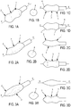
- the Figure 1A thus illustrates a first geometric form of an applicator device according to the invention.
- Its outer general shape is elongated and axisymmetric around an axis XX.
- This general shape comprises a first enlarged volume 1 connected to a second bulged volume 2 by a thinner zone 3 in the sense that its cross section is smaller than the largest cross section of the first 1 and the second 2 bulged volume.
- This form includes some variants, illustrated on the FIGS. 1A, 2A and 3A .
- This form has been studied to perfectly fit so-called complex surfaces, that is to say non-flat and defined by curves.
- These are volume shapes that allow the user to rotate the device around the axis XX, to deposit the product uniformly on the curved surface.
- the general external shape of the device resembles that of a peanut; this form is particularly suitable for depositing product on lips; the first 1 and the second 2 volumes have substantially the same size.
- a tapered portion or tip 4 is preferably provided at the distal end of the device.
- distal end is meant the end longitudinally disposed opposite the end adapted to receive the rod 5 of a gripping means of the applicator device.
- the skilled person can taper at a chosen angle the tip 4 which can, without departing from the scope of the invention, be rounded.
- a second embodiment of the invention as to the general external shape, is illustrated on the Figures 2A, 2B, 2C and 2D .
- the first corresponds to half a volume of the first embodiment, which, therefore, will not be further explained;
- the second half volume comprises an axially curved portion disposed substantially at the level of the thinnest portion 3.
- This drawing will preferably be chosen for the application of product on the lips.
- the Figure 2B clearly shows this difference in the half volumes.
- FIGS. 3a, 3b, 3c and 3d show a third embodiment, of generally curved shape which is clearly visible on the 3D figure .
- Complex shapes can be obtained if the device is obtained by molding, with or without addition of material. As will be explained later, the device can be single-component or two-component, depending on the technical constraints.
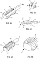
- the applicator device comprises in particular at least one flexible longitudinal arch 10, 11 embedded in at least one point 101; 111, 112 on a soul 15.
- the solid volume constituting the device excluding the arch or arches 10, 11.
- the core extends longitudinally along the axis XX.
- the arches 10 are embedded in a single point 101; this point is in particular located at one end of the arch 10 which is thus arranged cantilevered on the core 15. Greater flexibility is thus imparted to this type of arch 10.
- the arches 10, 11 are elongated and thin (length to thickness ratio of the order of 10/1) to inherently present a certain flexibility.
- the chosen subject participates in flexibility; for example, a thermoplastic material, a vulcanizable elastomer or any technically equivalent material is chosen.
- the arch or arches 10, 11 have a corrugated shape along the axis XX.
- the device comprises an arch 10 embedded in a single point 101, and a plurality of arches 11 embedded in two points 111, 112.
- the device comprises a few arches 10 cantilevered radially surrounded by arches 11 embedded at their two ends 111, 112.
- the arches 10, 11 define with the core 15 a product reservoir of variable volume capable of obtaining a pumping effect of the product present in said reservoir.
- the tank is here defined by the volume between the arches 10, 11 and the core 15.
- the arches being flexible, their deformations generate a variation in the volume of the tank, a pumping effect of the fluid or pasty product.
- FIGS. 6A, 6B, 6C and 6D show an embodiment according to which the arches are all of the type 11, ie recessed in two points 111 and 112.
- the arches 11 are identical to each other and distributed in a half-cylindrical volume; they are angularly distributed regularly as clearly Figures 6B and 6D .
- the second half volume 6 may be full or empty of material, at the choice of the skilled person.
- FIG. 7A illustrates a particular example where a single arch 11 is provided, recessed at both ends.
- Figures 7B to 7E represent, by schematic cross sections, different variants corresponding to different positions of the arches; the Figure 7B is a cross-section of the device according to the Figure 7A , according to the AA section.
- Figure 7C three substantially identical arches are provided, placed side by side in a small angular sector (of the order of 90 °).
- three arches are planned; they are not identical in shape, in particular one is thicker and therefore stiff than the others.
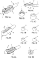
- the Figures 8A and 8B correspond to an embodiment where all the arches 11 are recessed type at each of their ends. They are angularly regularly distributed, and have different shapes. Although this concept seems difficult to achieve, currently available technologies allow for easy, mass manufacturing.
- FIGS. 9 and 10 illustrate an applicator element comprising an applicator device. It is clearly seen that the device cooperates with the rod 5, is carried by its opposite end to a container cap closure type gripping means, well known per se. According to figure 9 , the device has a general external shape in peanut, and it comprises arches 10 cantilevered (three in number) angularly surrounded by arches 11.
- the device further comprises pins 12 protruding vis-à-vis the outer surface they emerge; the pins 12 can be present on the outer surface of one or more arches 10, 11 and / or on the outer surface of the core 15, more precisely here of the half-volume 6.
- the Figures 11A and 11B relate to an embodiment having arches 11 and a half-volume 6; studs 12 are evenly distributed on the outer surface of the half-volume 6, allowing better product retention; they also offer a rough surface, for example for scrubbing and / or cleaning the skin.
- FIGS 12A and 12B show an alternative embodiment according to which the pins are distributed over the arches 11. A product retention effect is here sought at the arches.
Description
L'invention se rapporte au domaine de la cosmétique et notamment du maquillage, du traitement cosmétique du visage. Plus particulièrement la présente invention concerne l'application de produit cosmétique et/ou de soin, fluide ou pâteux, sur le visage mais également sur d'autres parties du corps, de forme complexe.The invention relates to the field of cosmetics and in particular makeup, cosmetic treatment of the face. More particularly, the present invention relates to the application of cosmetic and / or care product, fluid or pasty, on the face but also on other parts of the body, of complex shape.
L'invention trouve un intérêt particulier dès qu'il s'agit d'appliquer de façon simple et efficace un tel produit, sur des surfaces complexes telles que les lèvres. Par surfaces complexes il faut comprendre des surfaces non planes, par exemple présentant dans l'espace une succession de courbures concaves et convexes.The invention is of particular interest when it comes to simply and effectively applying such a product on complex surfaces such as lips. By complex surfaces it is necessary to understand non-planar surfaces, for example having in space a succession of concave and convex curvatures.
En outre, lorsqu'ils coopèrent avec un réservoir présentant un col doté d'un orifice circulaire de petit diamètre, de tels applicateurs doivent être suffisamment souples et élastiques pour passer à travers l'orifice circulaire, s'y déformer, puis reprendre leur forme initiale, tout en retenant le produit fluide ou pâteux qu'il s'agit d'appliquer sur la surface extérieure complexe.In addition, when they cooperate with a reservoir having a neck with a small diameter circular orifice, such applicators must be sufficiently flexible and resilient to pass through the circular orifice, deform and then return to their shape. initially, while retaining the fluid or pasty product that it is to apply on the complex outer surface.
De nombreux applicateurs ont déjà été proposés; un grand nombre concerne l'application de produit pâteux sur des fibres kératiniques telles que des cils ou des sourcils. Mais la problématique n'est pas exactement la même lorsqu'il s'agit d'appliquer un tel produit de façon simple, uniforme et efficace sur des surfaces complexes.Many applicators have already been proposed; a large number relates to the application of pasty product on keratinous fibers such as eyelashes or eyebrows. But the problem is not exactly the same when it comes to applying such a product in a simple, uniform and effective way on complex surfaces.
A titre illustratif, le dispositif applicateur décrit dans le document
On connait aussi le document
La demande de brevet
On connait par ailleurs des dispositifs applicateurs de « gloss » (ou produit pâteux) tels que décrits par exemple dans le document
En outre, les microfibres générées par le flocage et présentes en surface des applicateurs de ce type, rendent ces applicateurs peu hygiéniques car elles favorisent la rétention et le développement local de bactéries. Cet aspect, très négatif, constitue un inconvénient non négligeable de tous les applicateurs munis de surfaces floquées.In addition, microfibers generated by flocking and present on the surface of applicators of this type, make these applicators unhygienic because they promote the retention and local development of bacteria. This aspect, very negative, is a significant disadvantage of all applicators with flocked surfaces.
On connait aussi un applicateur selon la demande
L'invention vise à remédier aux inconvénients de l'état de la technique et notamment à proposer un applicateur de produit fluide, liquide ou pâteux, dans le domaine de la cosmétique ou du soin, qui permette d'appliquer le produit sur des surfaces complexes tout en conservant une charge optimale de produit malgré le passage à travers un orifice de petit diamètre.The invention aims to remedy the drawbacks of the state of the art and in particular to propose a fluid, liquid or pasty product applicator, in the field of cosmetics or care, which makes it possible to apply the product to complex surfaces. while maintaining an optimal product load despite passing through a small diameter orifice.
Pour ce faire est proposé un dispositif applicateur selon la revendication 1.For this purpose, an applicator device according to
Par arche longitudinale on entend un élément effilé qui s'étend sensiblement selon l'axe XX longitudinal du dispositif.By longitudinal arch is meant a tapered element which extends substantially along the longitudinal axis XX of the device.
L'effet de pompage du produit n'est pas obtenu dans l'art antérieur du domaine considéré c'est-à-dire pour l'application de produit fluide ou pâteux sur des surfaces complexes. Ainsi, de façon nouvelle et inventive, la présente invention permet notamment un traitement ou un maquillage des lèvres ou de toute autre surface complexe de ce type. En particulier la forme générale extérieure galbée de l'applicateur permet de se conformer à diverses formes pour l'application.The pumping effect of the product is not obtained in the prior art of the field considered, that is to say for the application of fluid or pasty product on complex surfaces. Thus, in a new and inventive way, the present invention allows in particular a treatment or a make-up of the lips or any other complex surface of this type. In particular, the generally curved outer shape of the applicator makes it possible to conform to various forms for the application.
De façon préférée, le dispositif est monobloc.Preferably, the device is monobloc.
En outre, le dispositif selon l'invention peut comprendre une pointe effilée prévue à l'une de ses extrémités longitudinales. Cette pointe permet par exemple de tracer des contours avec davantage de précision.In addition, the device according to the invention may comprise a tapered tip provided at one of its longitudinal ends. This tip allows for example to draw contours with more precision.
De façon avantageuse, le dispositif comprend plusieurs arches radialement espacées autour de l'âme. Par plusieurs arches, on entend couramment de deux à trente-six arches.Advantageously, the device comprises several arches radially spaced around the core. By several arches one commonly hears from two to thirty-six arches.
Selon un mode particulier de réalisation de l'invention, ladite au moins une arche présente une forme ondulée selon l'axe XX.According to a particular embodiment of the invention, said at least one arch has a corrugated shape along the axis XX.
Avantageusement, ladite âme comprend un volume complémentaire au volume extérieurement défini par ladite au moins une arche, ledit volume représentant entre 5% et 95% du volume total du dispositif. Bien entendu l'ensemble présente la forme générale extérieure définie plus haut. Le volume complémentaire peut être plein ou partiellement plein de matière.Advantageously, said core comprises a volume complementary to the volume externally defined by said at least one arch, said volume representing between 5% and 95% of the total volume of the device. Of course, the assembly has the general external shape defined above. The complementary volume may be full or partially full of material.
Selon une caractéristique de l'invention, le dispositif applicateur comprend en outre des picots saillants vis-à-vis de la surface extérieure de ladite au moins une arche et/ou de l'âme. Cette caractéristique améliore la tenue du produit sur l'applicateur. Par picots saillants, on entend tout relief ou excroissance, de préférence allongé, qui s'étend en dehors de la surface extérieure des arches et/ou de l'âme.According to a feature of the invention, the applicator device further comprises protruding pins vis-à-vis the outer surface of said at least one arch and / or the core. This feature improves the strength of the product on the applicator. The term "protruding pins" means any relief or protuberance, preferably elongated, that extends outside the outer surface of the arches and / or the core.
Conformément à un mode de réalisation de l'invention, le dispositif comprend au moins une arche encastrée en un point et au moins une arche encastrée en deux points de l'âme. Bien entendu de nombreuses combinaisons peuvent être réalisées sur cette base ; l'homme de métier choisira en fonction du cas particulier d'application.According to one embodiment of the invention, the device comprises at least one recessed arch at a point and at least one recessed arch at two points of the core. Of course, many combinations can be made on this basis; the skilled person will choose according to the particular case of application.
Selon encore une caractéristique de l'invention, lesdites arches encastrées présentent une longueur comprise entre 70% et 95% de la longueur totale du dispositif.According to another characteristic of the invention, said recessed arches have a length of between 70% and 95% of the total length of the device.
En accord avec l'invention, lesdites arches encastrées en un point présentent une extrémité libre orientée vers l'intérieur du volume du dispositif. Cet aspect diminue les risques de voir de telles arches se courber voire se casser lors de certaines manipulations.In accordance with the invention, said arches recessed at a point have a free end oriented towards the inside of the volume of the device. This aspect reduces the risk of such arches bending or breaking during certain manipulations.
De façon préférée, lesdits picots s'étendent perpendiculairement à la surface sur laquelle ils sont encastrés.Preferably, said pins extend perpendicularly to the surface on which they are embedded.
A titre préféré, le dispositif peut être mono-composant, ou bi-composant, obtenu par moulage, avec ou sans addition de matière.As a preference, the device may be single-component, or two-component, obtained by molding, with or without addition of material.
Selon l'invention, le dispositif applicateur peut être obtenu par un procédé d'injection, de bi-injection, de co-injection, de moulage, de surmoulage, de compression, de coulage, de stéréo-lithographie, d'agencement de matière et/ou d'ajout d'au moins une couche de matière.According to the invention, the applicator device can be obtained by a method of injection, bi-injection, coinjection, molding, overmolding, compression, casting, stereo-lithography, material arrangement. and / or adding at least one layer of material.
En outre, il peut être réalisé en une matière thermoplastique, en élastomère vulcanisable ou toute matière techniquement équivalente.In addition, it can be made of a thermoplastic material, vulcanizable elastomer or any technically equivalent material.
D'autres caractéristiques et avantages de l'invention ressortiront à la lecture de la description qui suit, en référence aux figures annexées, qui illustrent :
- la
figure 1A , une vue en perspective d'une première forme d'applicateur selon un premier mode de réalisation de l'invention ; - la
figure 1B , une vue de face de la première forme d'applicateur ; - la
figure 1C , une vue de dessus de la première forme d'applicateur ; - la
figure 1D , une vue de côté de la première forme d'applicateur ; - la
figure 2A , une vue en perspective d'une deuxième forme d'applicateur selon un deuxième mode de réalisation de l'invention ; - la
figure 2B , une vue de face de la deuxième forme d'applicateur ; - la
figure 2C , une vue de dessus de la deuxième forme d'applicateur ; - la
figure 2D , une vue de côté de la deuxième forme d'applicateur ; - la
figure 3A , une vue en perspective d'une troisième forme d'applicateur selon un troisième mode de réalisation de l'invention ; - la
figure 3B , une vue de face de la troisième forme d'applicateur ; - la
figure 3C , une vue de dessus de la troisième forme d'applicateur ; - la
figure 3D , une vue de côté de la troisième forme d'applicateur ; - la
figure 4A , une vue en perspective d'une quatrième forme d'applicateur ; - la
figure 4B une vue en perspective d'une extrémité de l'applicateur selon la quatrième forme de réalisation de l'invention ; - la
figure 4C , une coupe longitudinale selon AA de lafigure 4A ; - la
figure 5A , une vue en perspective d'une cinquième forme d'exécution de l'applicateur ; - la
figure 5B , une perspective de l'extrémité de la cinquième forme d'exécution de l'applicateur selon l'invention ; - la
figure 6A , une vue en perspective détaillée d'un applicateur ne faisant pas partie de l'invention. - la
figure 6B , une vue de face de l'applicateur selon lafigure 6A ; - la
figure 6C , une vue de côté d'un applicateur selon lafigure 6A ; - la
figure 6D , une coupe transversale selon AA de lafigure 6C ; - la
figure 7A , une vue en perspective détaillée d'un applicateur ne faisant pas partie de l'invention. - les
figures 7B à 7E , des coupes transversales selon AA de lafigure 7A , pour plusieurs variantes de réalisation ; - la
figure 8A , une vue en perspective détaillée d'un applicateur ne faisant pas partie de l'invention. - la
figure 8B , une coupe transversale selon AA de lafigure 8A ; - la
figure 9 , une vue en perspective d'un dispositif d'application selon l'invention, disposé sur un élément applicateur ; - la
figure 10 , une vue en perspective d'un dispositif d'application ne faisant pas partie de l'invention, disposé sur un élément applicateur ; - la
figure 11A , une vue en perspective détaillée d'un dispositif selon un mode de réalisation ne faisant pas partie de l'invention, présentant des picots ; - la
figure 11B , une vue de côté du dispositif représenté sur lafigure 11A ; - la
figure 12A , une vue en perspective détaillée du dispositif ne faisant pas partie de l'invention, présentant des picots ; - la
figure 12B , une vue de côté du dispositif représenté sur lafigure 12A ; - la
figure 13A , une vue en perspective détaillée d'un mode de réalisation ne faisant pas partie de l'invention, muni de picots ; et - la
figure 13B , une vue de côté du dispositif selon lafigure 13A .
- the
Figure 1A a perspective view of a first form of applicator according to a first embodiment of the invention; - the
Figure 1B a front view of the first form of applicator; - the
figure 1C a top view of the first form of applicator; - the
figure 1D a side view of the first form of applicator; - the
Figure 2A a perspective view of a second form of applicator according to a second embodiment of the invention; - the
Figure 2B a front view of the second form of applicator; - the
Figure 2C a top view of the second form of applicator; - the
2D figure a side view of the second form of applicator; - the
figure 3A a perspective view of a third form of applicator according to a third embodiment of the invention; - the
figure 3B a front view of the third form of applicator; - the
figure 3C a top view of the third form of applicator; - the
3D figure a side view of the third form of applicator; - the
Figure 4A a perspective view of a fourth form of applicator; - the
Figure 4B a perspective view of an end of the applicator according to the fourth embodiment of the invention; - the
figure 4C , a longitudinal section along AA of theFigure 4A ; - the
Figure 5A a perspective view of a fifth embodiment of the applicator; - the
Figure 5B , a perspective of the end of the fifth embodiment of the applicator according to the invention; - the
Figure 6A , a detailed perspective view of an applicator not forming part of the invention. - the
Figure 6B , a front view of the applicator according to theFigure 6A ; - the
Figure 6C , a side view of an applicator according to theFigure 6A ; - the
Figure 6D , a cross-section along AA of theFigure 6C ; - the
Figure 7A , a detailed perspective view of an applicator not forming part of the invention. - the
Figures 7B to 7E , cross-sections according to AA of theFigure 7A for several variants; - the
figure 8A , a detailed perspective view of an applicator not forming part of the invention. - the
Figure 8B , a cross-section along AA of thefigure 8A ; - the
figure 9 , a perspective view of an application device according to the invention, disposed on an applicator element; - the
figure 10 a perspective view of an application device not forming part of the invention, disposed on an applicator element; - the
figure 11A a detailed perspective view of a device according to an embodiment not forming part of the invention, having pins; - the
Figure 11B , a side view of the device shown on thefigure 11A ; - the
figure 12A a detailed perspective view of the device not forming part of the invention, having pins; - the
figure 12B , a side view of the device shown on thefigure 12A ; - the
figure 13A a detailed perspective view of an embodiment not forming part of the invention provided with pins; and - the
Figure 13B , a side view of the device according to thefigure 13A .
Pour plus de clarté, les éléments identiques ou similaires sont repérés par des signes de référence identiques sur l'ensemble des figures.For the sake of clarity, identical or similar elements are marked with identical reference signs throughout the figures.
La
Selon le mode de réalisation des
Un deuxième mode de réalisation de l'invention, quant à la forme extérieure générale, est illustré sur les
Les
Les
Les arches 10 sont encastrées en un seul point 101 ; ce point est notamment situé à l'une des extrémités de l'arche 10 qui est ainsi disposée en porte à faux sur l'âme 15. Une plus grande flexibilité est ainsi conférée à ce type d'arche 10. En elles-mêmes les arches 10, 11 sont allongées et fines (ratio longueur sur épaisseur de l'ordre de 10/1) afin de présenter intrinsèquement une certaine flexibilité. La matière choisie participe à la flexibilité ; on choisit par exemple une matière thermoplastique, un élastomère vulcanisable ou toute matière techniquement équivalente.The
Afin de conférer la forme générale extérieure caractéristique de l'invention, la ou les arches 10, 11 présentent une forme ondulée selon l'axe XX.In order to confer the general external shape characteristic of the invention, the arch or
Sur les
Sur les
Les arches 10, 11 définissent avec l'âme 15 un réservoir de produit, de volume variable apte à obtenir un effet de pompage du produit présent dans ledit réservoir. Le réservoir est ici défini par le volume entre les arches 10, 11 et l'âme 15. Les arches étant flexibles, leurs déformations génèrent une variation du volume du réservoir, soit un effet de pompage du produit fluide ou pâteux.The
L'homme de métier choisira, en fonction de différents paramètres, le nombre et la répartition des arches 10, 11.The skilled person will choose, depending on different parameters, the number and distribution of the
Les
La
Les
Les
Sur la
Les
Les
Les
D'autres combinaisons des caractéristiques décrites ci-avant peuvent être imaginées et mises en oeuvre par l'homme de métier sans sortir du cadre de l'invention selon la revendication 1.Other combinations of the characteristics described above can be imagined and implemented by those skilled in the art without departing from the scope of the invention according to
Claims (14)
- An applicator device for a fluid or paste-like product of the make-up and/or care product type across a complex surface of the human body, having an elongated general outer shape axisymmetric about an XX axis; wherein the general outer shape thereof comprises a first rounded volume (1) connected to a second rounded volume (2) through an area (3) with a cross-section smaller than the largest cross-section of the first and/or the second volume, characterized in that it comprises at least one flexible longitudinal arch (10) embedded at only one end (101) into a core (15) extending along the XX axis, with the arch being so positioned as to overhang above the core, with said at least one arch being suitable for defining with the core a product reservoir having a variable volume, resulting in the pumping of the product.
- A device according to claim 1, characterized in that it is made of a single piece.
- A device according to any one of the preceding claims, characterized in that it further comprises a tapered tip (4) provided at one of its longitudinal ends.
- A device according to any one of the preceding claims, characterized in that it comprises a plurality of arches (10, 11) radially spaced around the core (15).
- A device according to one of the preceding claims, characterized in that said at least one arch (10, 11) has a corrugated shape along the XX axis.
- A device according to one of the preceding claims, characterized in that said core (15) comprises a volume complementary to the volume defined externally by said at least one arch (10, 11), with said volume representing between 5% and 95% of the total volume of the device.
- A device according to one of the preceding claims, characterized in that it further comprises sprockets (12) protruding from the outer surface of said at least one arch and/or from the core (15).
- A device according to one of the preceding claims, characterized in that it comprises at least one arch (10) embedded at only one end and at least one arch (11) embedded at two points of the core.
- A device according to one of the preceding claims, characterized in that said arches (10) embedded at only one end (101) have a length ranging from 70% to 95% of the total length of the device.
- A device according to one of the preceding claims, characterized in that said arches (10) embedded at only one end (101) have a free end (102) oriented towards the interior volume of the device.
- A device according to one of claims 7 to 10, characterized in that said sprockets (12) extend perpendicularly to the surface wherein they are embedded.
- A device according to one of the preceding claims, characterized in that it comprises from 1 arch to 36 arches.
- A device according to any one of the preceding claims, characterized in that it is obtained by means of an injection, bi-injection, co-injection, molding, overmolding, compression, casting, stereo-lithography, material arrangement method and/or the addition of at least one material layer.
- A device according to any one of the preceding claims, characterized in that it is made of a thermoplastic material, of a curable elastomer or a technically equivalent material.
Applications Claiming Priority (1)
| Application Number | Priority Date | Filing Date | Title |
|---|---|---|---|
| PCT/FR2014/052333 WO2016042216A1 (en) | 2014-09-19 | 2014-09-19 | Applicator device for applying flowable product across a complex surface. |
Publications (2)
| Publication Number | Publication Date |
|---|---|
| EP3193663A1 EP3193663A1 (en) | 2017-07-26 |
| EP3193663B1 true EP3193663B1 (en) | 2019-04-10 |
Family
ID=51690408
Family Applications (1)
| Application Number | Title | Priority Date | Filing Date |
|---|---|---|---|
| EP14783664.7A Active EP3193663B1 (en) | 2014-09-19 | 2014-09-19 | Applicator device for applying flowable product across a complex surface |
Country Status (3)
| Country | Link |
|---|---|
| US (1) | US20170360185A1 (en) |
| EP (1) | EP3193663B1 (en) |
| WO (1) | WO2016042216A1 (en) |
Families Citing this family (12)
| Publication number | Priority date | Publication date | Assignee | Title |
|---|---|---|---|---|
| FR3039382B1 (en) | 2015-07-31 | 2017-08-11 | Montaigu Dev | DEVICE APPLICATOR OF A FLUID OR PASTY PRODUCT ON KERATIN FIBERS. |
| WO2017115022A1 (en) * | 2015-12-30 | 2017-07-06 | Montaigu Developpement | Device for applying a fluid or pasty product to keratinous fibres |
| FR3053581B1 (en) * | 2016-07-07 | 2019-08-02 | Chanel Parfums Beaute | COSMETIC PRODUCT APPLICATOR |
| FR3068224B1 (en) * | 2017-06-30 | 2021-10-01 | Albea Services | APPLICATOR TIP FOR COSMETIC PRODUCT, ASSOCIATED APPLICATOR AND APPLICATOR SET |
| FR3075023B1 (en) * | 2017-12-19 | 2020-01-10 | L'oreal | ORGAN FOR APPLYING A PRODUCT, ESPECIALLY COSMETIC, AND PACKAGING AND APPLICATION ASSEMBLY FOR A PRODUCT COMPRISING SAID APPLICATION ORGAN |
| US20210085056A1 (en) * | 2019-04-14 | 2021-03-25 | Toly Management Ltd. | Cosmetic applicator with facial application member and pump |
| KR102535039B1 (en) | 2019-04-14 | 2023-05-22 | 톨리 매니지먼트 엘티디. | Cosmetic applicator with flexible fluid retaining portion |
| FR3101233B1 (en) * | 2019-09-27 | 2021-09-10 | Albea Services | Applicator for cosmetic product, in particular mascara, associated applicator assembly and method of manufacturing such an applicator |
| FR3104919A1 (en) * | 2019-12-20 | 2021-06-25 | Albea Services | Applicator tip for cosmetic product, associated applicator and applicator assembly |
| WO2023275581A1 (en) | 2021-06-30 | 2023-01-05 | Societe Industrielle De Matieres Plastiques | Applicator device for applying a fluid or pasty cosmetic product, obtained by moulding a biomaterial, and associated biomaterial |
| WO2023144452A1 (en) * | 2022-01-27 | 2023-08-03 | Societe Industrielle De Matieres Plastiques | Applicator device for applying a fluid or paste product to keratin fibres |
| US11758997B1 (en) | 2022-06-10 | 2023-09-19 | APR Beauty Group, Inc. | Applicator head for applying a cosmetic product |
Citations (2)
| Publication number | Priority date | Publication date | Assignee | Title |
|---|---|---|---|---|
| EP1920677A1 (en) * | 2006-11-09 | 2008-05-14 | Geka Brush Gmbh | Applicator for a cosmetic product for the lips |
| US20080219748A1 (en) * | 2007-02-21 | 2008-09-11 | Chanel Parfums Beaute | Method for manufacturing a cosmetic applicator, an applicator, a package including the applicator, and a batch of applicators |
Family Cites Families (23)
| Publication number | Priority date | Publication date | Assignee | Title |
|---|---|---|---|---|
| FR2762494B1 (en) * | 1997-04-28 | 1999-06-25 | Oreal | APPLICATOR AND PACKAGING AND APPLICATION ASSEMBLY USING SUCH AN APPLICATOR |
| FR2810860B1 (en) * | 2000-06-28 | 2003-02-21 | Oreal | DEVICE FOR APPLYING A PRODUCT TO EYELASHES OR EYEBROWS |
| FR2872999B1 (en) * | 2004-07-13 | 2007-09-07 | Oreal | DEVICE FOR PACKAGING AND APPLYING A COSMETIC OR CARE PRODUCT |
| FR2886113B1 (en) * | 2005-05-24 | 2007-10-05 | Oreal | APPLICATOR FOR APPLYING A PRODUCT ON THE LASHES AND / OR THE EYE |
| FR2895887A1 (en) * | 2006-01-12 | 2007-07-13 | Techpack Int Sa | Applicator for cosmetic product such as mascara comprises stem with holder on one end and moulded tip with product retaining cavity on other |
| FR2920283B1 (en) * | 2007-08-31 | 2010-02-26 | Chanel Parfums Beaute | MASCARA APPLICATOR COMPRISING A COMB |
| GB2463415A (en) * | 2007-09-06 | 2010-03-17 | Revlon Consumer Prod Corp | Device for applying a substance to keratinous fibers |
| FR2945418B1 (en) * | 2009-05-15 | 2012-09-21 | Oreal | DEVICE FOR CONDITIONING AND APPLICATION. |
| KR101353676B1 (en) * | 2009-05-18 | 2014-01-20 | 이엘씨 매니지먼트 엘엘씨 | Compressible cosmetic applicator |
| WO2011158173A1 (en) * | 2010-05-17 | 2011-12-22 | L'oreal | A device for applying a composition to the eyelashes and/or the eyebrows |
| FR2969470B1 (en) * | 2010-12-24 | 2015-06-19 | Ile Mvr Soc Civ | NOVEL APPLICATOR DEVICE FOR A FLUID ON KERATIN FIBERS |
| FR2989256B1 (en) * | 2012-04-11 | 2014-11-28 | Oreal | DEVICE FOR PACKAGING AND APPLYING A COSMETIC OR CARE PRODUCT ON LIP |
| FR2993151B1 (en) * | 2012-07-16 | 2014-07-25 | Albea Services | APPLICATOR FOR COSMETIC PRODUCT AND ASSOCIATED APPLICATOR ASSEMBLY |
| USD682556S1 (en) * | 2012-07-26 | 2013-05-21 | Albea Services | Mascara brush |
| FR3004905B1 (en) * | 2013-04-26 | 2016-02-12 | Oreal | APPLICATOR FOR APPLYING A PRODUCT ON THE LASHES AND / OR THE EYE |
| FR3019016B1 (en) * | 2014-03-25 | 2017-09-01 | Albea Services | APPLICATOR FOR COSMETIC PRODUCT, IN PARTICULAR MASCARA AND METHOD FOR MANUFACTURING SUCH APPLICATOR |
| DE202014103653U1 (en) * | 2014-08-06 | 2015-11-09 | Geka Gmbh | By surface elements interconnected, adjacent bristles |
| FR3025986B1 (en) * | 2014-09-22 | 2016-12-09 | Oreal | COSMETIC OR CARE PRODUCT APPLICATOR |
| FR3035779B1 (en) * | 2015-05-06 | 2017-09-01 | Oreal | APPLICATOR FOR THE APPLICATION OF A COSMETIC PRODUCT |
| FR3053223B1 (en) * | 2016-06-30 | 2019-07-19 | Albea Services | APPLICATOR FOR COSMETIC PRODUCT AND APPLICATOR ASSEMBLY COMPRISING SUCH APPLICATOR |
| US11882926B2 (en) * | 2016-08-31 | 2024-01-30 | Zen Design Solutions Limited | Adjustable applicator |
| DE202017100134U1 (en) * | 2017-01-12 | 2018-04-15 | Geka Gmbh | Applicator with resiliently mounted on special leaf spring elements bristles |
| FR3075023B1 (en) * | 2017-12-19 | 2020-01-10 | L'oreal | ORGAN FOR APPLYING A PRODUCT, ESPECIALLY COSMETIC, AND PACKAGING AND APPLICATION ASSEMBLY FOR A PRODUCT COMPRISING SAID APPLICATION ORGAN |
-
2014
- 2014-09-19 US US15/511,567 patent/US20170360185A1/en not_active Abandoned
- 2014-09-19 WO PCT/FR2014/052333 patent/WO2016042216A1/en active Application Filing
- 2014-09-19 EP EP14783664.7A patent/EP3193663B1/en active Active
Patent Citations (2)
| Publication number | Priority date | Publication date | Assignee | Title |
|---|---|---|---|---|
| EP1920677A1 (en) * | 2006-11-09 | 2008-05-14 | Geka Brush Gmbh | Applicator for a cosmetic product for the lips |
| US20080219748A1 (en) * | 2007-02-21 | 2008-09-11 | Chanel Parfums Beaute | Method for manufacturing a cosmetic applicator, an applicator, a package including the applicator, and a batch of applicators |
Also Published As
| Publication number | Publication date |
|---|---|
| EP3193663A1 (en) | 2017-07-26 |
| US20170360185A1 (en) | 2017-12-21 |
| WO2016042216A1 (en) | 2016-03-24 |
Similar Documents
| Publication | Publication Date | Title |
|---|---|---|
| EP3193663B1 (en) | Applicator device for applying flowable product across a complex surface | |
| EP2654490B1 (en) | Novel device for applying a fluid to keratin fibres | |
| CA2314470C (en) | Apparatus for conditioning and applying a product to eyelashes or eyebrows | |
| EP3420845B1 (en) | Cosmetic-product applicator tip, associated applicator and applicator unit | |
| EP1115303B1 (en) | Device for applying a product on keratinous fibres | |
| CA2351800C (en) | Device for the application of a product on the eyelashes or eyebrows | |
| EP3261487B1 (en) | Applicator device for applying a product of the fluid or pasty type to keratin fibres | |
| EP3397111A1 (en) | Device for applying a fluid or pasty product to keratinous fibres | |
| EP2265146B1 (en) | Device for applying a fluid or a pasty cosmetic product, typically mascara | |
| WO2017098134A1 (en) | Cosmetic applicator comprising projecting loops | |
| EP2865292B1 (en) | Applicator for a cosmetic product and associated applicator assembly | |
| EP3282888B1 (en) | Device for applying a flowing or paste-like product to keratin fibres | |
| FR3035779A1 (en) | APPLICATOR FOR THE APPLICATION OF A COSMETIC PRODUCT | |
| FR2937514A1 (en) | Applicator device i.e. brush, for applying e.g. mascara on eyelashes, has picots obtained by molding with core and distributed along rows parallel to axle of core, where picots of same row extend in projection from core in curved manner | |
| WO2016202983A1 (en) | Cosmetic applicator | |
| EP4041026B1 (en) | Mascara applicator | |
| WO2021123335A1 (en) | Applicator end piece for applying cosmetic product, associated applicator and applicator assembly | |
| WO2018220286A1 (en) | Applicator for applying product to keratinous fibres with complex core | |
| FR3039381B1 (en) | APPLICATOR FOR COSMETIC PRODUCT AND ASSOCIATED APPLICATOR ASSEMBLY | |
| EP3110287B1 (en) | Cosmetic product applicator, in particular for mascara, and associated applicator assembly | |
| FR3060278B1 (en) | COSMETIC PRODUCT APPLICATOR DEVICE WITH FLEXIBLE APPLICATOR ELEMENT | |
| EP3110290B1 (en) | Applicator for a cosmetic product and associated applicator assembly | |
| FR3059877A1 (en) | "APPLICATOR FOR COSMETIC PRODUCT AND ASSOCIATED APPLICATOR ASSEMBLY" | |
| FR3070838A1 (en) | APPLICATOR FOR APPLYING A COSMETIC PRODUCT | |
| EP3136905A1 (en) | Applicator for cosmetic product, in particular mascara, and method for manufacturing such an applicator |
Legal Events
| Date | Code | Title | Description |
|---|---|---|---|
| STAA | Information on the status of an ep patent application or granted ep patent |
Free format text: STATUS: THE INTERNATIONAL PUBLICATION HAS BEEN MADE |
|
| TPAC | Observations filed by third parties |
Free format text: ORIGINAL CODE: EPIDOSNTIPA |
|
| PUAI | Public reference made under article 153(3) epc to a published international application that has entered the european phase |
Free format text: ORIGINAL CODE: 0009012 |
|
| STAA | Information on the status of an ep patent application or granted ep patent |
Free format text: STATUS: REQUEST FOR EXAMINATION WAS MADE |
|
| 17P | Request for examination filed |
Effective date: 20170317 |
|
| AK | Designated contracting states |
Kind code of ref document: A1 Designated state(s): AL AT BE BG CH CY CZ DE DK EE ES FI FR GB GR HR HU IE IS IT LI LT LU LV MC MK MT NL NO PL PT RO RS SE SI SK SM TR |
|
| AX | Request for extension of the european patent |
Extension state: BA ME |
|
| DAX | Request for extension of the european patent (deleted) | ||
| STAA | Information on the status of an ep patent application or granted ep patent |
Free format text: STATUS: EXAMINATION IS IN PROGRESS |
|
| 17Q | First examination report despatched |
Effective date: 20180503 |
|
| GRAP | Despatch of communication of intention to grant a patent |
Free format text: ORIGINAL CODE: EPIDOSNIGR1 |
|
| STAA | Information on the status of an ep patent application or granted ep patent |
Free format text: STATUS: GRANT OF PATENT IS INTENDED |
|
| INTG | Intention to grant announced |
Effective date: 20190131 |
|
| GRAS | Grant fee paid |
Free format text: ORIGINAL CODE: EPIDOSNIGR3 |
|
| GRAA | (expected) grant |
Free format text: ORIGINAL CODE: 0009210 |
|
| STAA | Information on the status of an ep patent application or granted ep patent |
Free format text: STATUS: THE PATENT HAS BEEN GRANTED |
|
| AK | Designated contracting states |
Kind code of ref document: B1 Designated state(s): AL AT BE BG CH CY CZ DE DK EE ES FI FR GB GR HR HU IE IS IT LI LT LU LV MC MK MT NL NO PL PT RO RS SE SI SK SM TR |
|
| REG | Reference to a national code |
Ref country code: GB Ref legal event code: FG4D Free format text: NOT ENGLISH |
|
| REG | Reference to a national code |
Ref country code: CH Ref legal event code: EP Ref country code: AT Ref legal event code: REF Ref document number: 1117507 Country of ref document: AT Kind code of ref document: T Effective date: 20190415 |
|
| REG | Reference to a national code |
Ref country code: IE Ref legal event code: FG4D Free format text: LANGUAGE OF EP DOCUMENT: FRENCH |
|
| REG | Reference to a national code |
Ref country code: DE Ref legal event code: R096 Ref document number: 602014044515 Country of ref document: DE |
|
| REG | Reference to a national code |
Ref country code: NL Ref legal event code: MP Effective date: 20190410 |
|
| REG | Reference to a national code |
Ref country code: LT Ref legal event code: MG4D |
|
| REG | Reference to a national code |
Ref country code: AT Ref legal event code: MK05 Ref document number: 1117507 Country of ref document: AT Kind code of ref document: T Effective date: 20190410 |
|
| PG25 | Lapsed in a contracting state [announced via postgrant information from national office to epo] |
Ref country code: NL Free format text: LAPSE BECAUSE OF FAILURE TO SUBMIT A TRANSLATION OF THE DESCRIPTION OR TO PAY THE FEE WITHIN THE PRESCRIBED TIME-LIMIT Effective date: 20190410 |
|
| PG25 | Lapsed in a contracting state [announced via postgrant information from national office to epo] |
Ref country code: FI Free format text: LAPSE BECAUSE OF FAILURE TO SUBMIT A TRANSLATION OF THE DESCRIPTION OR TO PAY THE FEE WITHIN THE PRESCRIBED TIME-LIMIT Effective date: 20190410 Ref country code: LT Free format text: LAPSE BECAUSE OF FAILURE TO SUBMIT A TRANSLATION OF THE DESCRIPTION OR TO PAY THE FEE WITHIN THE PRESCRIBED TIME-LIMIT Effective date: 20190410 Ref country code: PT Free format text: LAPSE BECAUSE OF FAILURE TO SUBMIT A TRANSLATION OF THE DESCRIPTION OR TO PAY THE FEE WITHIN THE PRESCRIBED TIME-LIMIT Effective date: 20190910 Ref country code: NO Free format text: LAPSE BECAUSE OF FAILURE TO SUBMIT A TRANSLATION OF THE DESCRIPTION OR TO PAY THE FEE WITHIN THE PRESCRIBED TIME-LIMIT Effective date: 20190710 Ref country code: HR Free format text: LAPSE BECAUSE OF FAILURE TO SUBMIT A TRANSLATION OF THE DESCRIPTION OR TO PAY THE FEE WITHIN THE PRESCRIBED TIME-LIMIT Effective date: 20190410 Ref country code: AL Free format text: LAPSE BECAUSE OF FAILURE TO SUBMIT A TRANSLATION OF THE DESCRIPTION OR TO PAY THE FEE WITHIN THE PRESCRIBED TIME-LIMIT Effective date: 20190410 Ref country code: SE Free format text: LAPSE BECAUSE OF FAILURE TO SUBMIT A TRANSLATION OF THE DESCRIPTION OR TO PAY THE FEE WITHIN THE PRESCRIBED TIME-LIMIT Effective date: 20190410 |
|
| PG25 | Lapsed in a contracting state [announced via postgrant information from national office to epo] |
Ref country code: BG Free format text: LAPSE BECAUSE OF FAILURE TO SUBMIT A TRANSLATION OF THE DESCRIPTION OR TO PAY THE FEE WITHIN THE PRESCRIBED TIME-LIMIT Effective date: 20190710 Ref country code: GR Free format text: LAPSE BECAUSE OF FAILURE TO SUBMIT A TRANSLATION OF THE DESCRIPTION OR TO PAY THE FEE WITHIN THE PRESCRIBED TIME-LIMIT Effective date: 20190711 Ref country code: LV Free format text: LAPSE BECAUSE OF FAILURE TO SUBMIT A TRANSLATION OF THE DESCRIPTION OR TO PAY THE FEE WITHIN THE PRESCRIBED TIME-LIMIT Effective date: 20190410 Ref country code: RS Free format text: LAPSE BECAUSE OF FAILURE TO SUBMIT A TRANSLATION OF THE DESCRIPTION OR TO PAY THE FEE WITHIN THE PRESCRIBED TIME-LIMIT Effective date: 20190410 Ref country code: PL Free format text: LAPSE BECAUSE OF FAILURE TO SUBMIT A TRANSLATION OF THE DESCRIPTION OR TO PAY THE FEE WITHIN THE PRESCRIBED TIME-LIMIT Effective date: 20190410 |
|
| PG25 | Lapsed in a contracting state [announced via postgrant information from national office to epo] |
Ref country code: AT Free format text: LAPSE BECAUSE OF FAILURE TO SUBMIT A TRANSLATION OF THE DESCRIPTION OR TO PAY THE FEE WITHIN THE PRESCRIBED TIME-LIMIT Effective date: 20190410 Ref country code: IS Free format text: LAPSE BECAUSE OF FAILURE TO SUBMIT A TRANSLATION OF THE DESCRIPTION OR TO PAY THE FEE WITHIN THE PRESCRIBED TIME-LIMIT Effective date: 20190810 |
|
| REG | Reference to a national code |
Ref country code: DE Ref legal event code: R097 Ref document number: 602014044515 Country of ref document: DE |
|
| PG25 | Lapsed in a contracting state [announced via postgrant information from national office to epo] |
Ref country code: SK Free format text: LAPSE BECAUSE OF FAILURE TO SUBMIT A TRANSLATION OF THE DESCRIPTION OR TO PAY THE FEE WITHIN THE PRESCRIBED TIME-LIMIT Effective date: 20190410 Ref country code: DK Free format text: LAPSE BECAUSE OF FAILURE TO SUBMIT A TRANSLATION OF THE DESCRIPTION OR TO PAY THE FEE WITHIN THE PRESCRIBED TIME-LIMIT Effective date: 20190410 Ref country code: EE Free format text: LAPSE BECAUSE OF FAILURE TO SUBMIT A TRANSLATION OF THE DESCRIPTION OR TO PAY THE FEE WITHIN THE PRESCRIBED TIME-LIMIT Effective date: 20190410 Ref country code: CZ Free format text: LAPSE BECAUSE OF FAILURE TO SUBMIT A TRANSLATION OF THE DESCRIPTION OR TO PAY THE FEE WITHIN THE PRESCRIBED TIME-LIMIT Effective date: 20190410 Ref country code: RO Free format text: LAPSE BECAUSE OF FAILURE TO SUBMIT A TRANSLATION OF THE DESCRIPTION OR TO PAY THE FEE WITHIN THE PRESCRIBED TIME-LIMIT Effective date: 20190410 |
|
| PLBE | No opposition filed within time limit |
Free format text: ORIGINAL CODE: 0009261 |
|
| STAA | Information on the status of an ep patent application or granted ep patent |
Free format text: STATUS: NO OPPOSITION FILED WITHIN TIME LIMIT |
|
| PG25 | Lapsed in a contracting state [announced via postgrant information from national office to epo] |
Ref country code: SM Free format text: LAPSE BECAUSE OF FAILURE TO SUBMIT A TRANSLATION OF THE DESCRIPTION OR TO PAY THE FEE WITHIN THE PRESCRIBED TIME-LIMIT Effective date: 20190410 |
|
| 26N | No opposition filed |
Effective date: 20200113 |
|
| PG25 | Lapsed in a contracting state [announced via postgrant information from national office to epo] |
Ref country code: TR Free format text: LAPSE BECAUSE OF FAILURE TO SUBMIT A TRANSLATION OF THE DESCRIPTION OR TO PAY THE FEE WITHIN THE PRESCRIBED TIME-LIMIT Effective date: 20190410 |
|
| PG25 | Lapsed in a contracting state [announced via postgrant information from national office to epo] |
Ref country code: MC Free format text: LAPSE BECAUSE OF FAILURE TO SUBMIT A TRANSLATION OF THE DESCRIPTION OR TO PAY THE FEE WITHIN THE PRESCRIBED TIME-LIMIT Effective date: 20190410 Ref country code: SI Free format text: LAPSE BECAUSE OF FAILURE TO SUBMIT A TRANSLATION OF THE DESCRIPTION OR TO PAY THE FEE WITHIN THE PRESCRIBED TIME-LIMIT Effective date: 20190410 |
|
| REG | Reference to a national code |
Ref country code: CH Ref legal event code: PL |
|
| PG25 | Lapsed in a contracting state [announced via postgrant information from national office to epo] |
Ref country code: CH Free format text: LAPSE BECAUSE OF NON-PAYMENT OF DUE FEES Effective date: 20190930 Ref country code: LI Free format text: LAPSE BECAUSE OF NON-PAYMENT OF DUE FEES Effective date: 20190930 Ref country code: IE Free format text: LAPSE BECAUSE OF NON-PAYMENT OF DUE FEES Effective date: 20190919 Ref country code: LU Free format text: LAPSE BECAUSE OF NON-PAYMENT OF DUE FEES Effective date: 20190919 |
|
| REG | Reference to a national code |
Ref country code: BE Ref legal event code: MM Effective date: 20190930 |
|
| PG25 | Lapsed in a contracting state [announced via postgrant information from national office to epo] |
Ref country code: BE Free format text: LAPSE BECAUSE OF NON-PAYMENT OF DUE FEES Effective date: 20190930 |
|
| PG25 | Lapsed in a contracting state [announced via postgrant information from national office to epo] |
Ref country code: ES Free format text: LAPSE BECAUSE OF FAILURE TO SUBMIT A TRANSLATION OF THE DESCRIPTION OR TO PAY THE FEE WITHIN THE PRESCRIBED TIME-LIMIT Effective date: 20190410 |
|
| PG25 | Lapsed in a contracting state [announced via postgrant information from national office to epo] |
Ref country code: CY Free format text: LAPSE BECAUSE OF FAILURE TO SUBMIT A TRANSLATION OF THE DESCRIPTION OR TO PAY THE FEE WITHIN THE PRESCRIBED TIME-LIMIT Effective date: 20190410 |
|
| PG25 | Lapsed in a contracting state [announced via postgrant information from national office to epo] |
Ref country code: HU Free format text: LAPSE BECAUSE OF FAILURE TO SUBMIT A TRANSLATION OF THE DESCRIPTION OR TO PAY THE FEE WITHIN THE PRESCRIBED TIME-LIMIT; INVALID AB INITIO Effective date: 20140919 Ref country code: MT Free format text: LAPSE BECAUSE OF FAILURE TO SUBMIT A TRANSLATION OF THE DESCRIPTION OR TO PAY THE FEE WITHIN THE PRESCRIBED TIME-LIMIT Effective date: 20190410 |
|
| PG25 | Lapsed in a contracting state [announced via postgrant information from national office to epo] |
Ref country code: MK Free format text: LAPSE BECAUSE OF FAILURE TO SUBMIT A TRANSLATION OF THE DESCRIPTION OR TO PAY THE FEE WITHIN THE PRESCRIBED TIME-LIMIT Effective date: 20190410 |
|
| PGFP | Annual fee paid to national office [announced via postgrant information from national office to epo] |
Ref country code: GB Payment date: 20230908 Year of fee payment: 10 |
|
| PGFP | Annual fee paid to national office [announced via postgrant information from national office to epo] |
Ref country code: FR Payment date: 20230929 Year of fee payment: 10 Ref country code: DE Payment date: 20230928 Year of fee payment: 10 |
|
| PGFP | Annual fee paid to national office [announced via postgrant information from national office to epo] |
Ref country code: IT Payment date: 20230927 Year of fee payment: 10 |