EP3192471A1 - Implant de resurfaçage de hanche - Google Patents
Implant de resurfaçage de hanche Download PDFInfo
- Publication number
- EP3192471A1 EP3192471A1 EP17153379.7A EP17153379A EP3192471A1 EP 3192471 A1 EP3192471 A1 EP 3192471A1 EP 17153379 A EP17153379 A EP 17153379A EP 3192471 A1 EP3192471 A1 EP 3192471A1
- Authority
- EP
- European Patent Office
- Prior art keywords
- implant
- rim
- cup
- acetabular
- implant according
- Prior art date
- Legal status (The legal status is an assumption and is not a legal conclusion. Google has not performed a legal analysis and makes no representation as to the accuracy of the status listed.)
- Granted
Links
- 239000007943 implant Substances 0.000 title claims abstract description 114
- 210000001624 hip Anatomy 0.000 claims abstract description 38
- 210000002239 ischium bone Anatomy 0.000 claims abstract description 8
- 210000003689 pubic bone Anatomy 0.000 claims abstract description 8
- 210000003692 ilium Anatomy 0.000 claims abstract description 7
- 210000000988 bone and bone Anatomy 0.000 claims description 46
- 210000004197 pelvis Anatomy 0.000 claims description 25
- 210000000588 acetabulum Anatomy 0.000 claims description 24
- 210000000689 upper leg Anatomy 0.000 description 48
- 238000000034 method Methods 0.000 description 17
- 238000003754 machining Methods 0.000 description 14
- 238000005520 cutting process Methods 0.000 description 10
- 210000002436 femur neck Anatomy 0.000 description 10
- 238000013461 design Methods 0.000 description 9
- 230000006870 function Effects 0.000 description 7
- 230000033001 locomotion Effects 0.000 description 7
- 210000003065 pyriform sinus Anatomy 0.000 description 7
- 238000002591 computed tomography Methods 0.000 description 6
- 238000012545 processing Methods 0.000 description 6
- 238000005304 joining Methods 0.000 description 5
- 210000004872 soft tissue Anatomy 0.000 description 5
- 241000817702 Acetabula Species 0.000 description 3
- 206010061209 Hip deformity Diseases 0.000 description 3
- 210000004204 blood vessel Anatomy 0.000 description 3
- 238000003780 insertion Methods 0.000 description 3
- 230000037431 insertion Effects 0.000 description 3
- 230000002262 irrigation Effects 0.000 description 3
- 238000003973 irrigation Methods 0.000 description 3
- 238000005259 measurement Methods 0.000 description 3
- 238000002360 preparation method Methods 0.000 description 3
- 210000002435 tendon Anatomy 0.000 description 3
- 206010017076 Fracture Diseases 0.000 description 2
- 238000009826 distribution Methods 0.000 description 2
- 210000000528 lesser trochanter Anatomy 0.000 description 2
- 238000004519 manufacturing process Methods 0.000 description 2
- 239000000203 mixture Substances 0.000 description 2
- 230000003287 optical effect Effects 0.000 description 2
- 210000003049 pelvic bone Anatomy 0.000 description 2
- 238000012360 testing method Methods 0.000 description 2
- 230000000451 tissue damage Effects 0.000 description 2
- 231100000827 tissue damage Toxicity 0.000 description 2
- 208000010392 Bone Fractures Diseases 0.000 description 1
- 206010058314 Dysplasia Diseases 0.000 description 1
- FAPWRFPIFSIZLT-UHFFFAOYSA-M Sodium chloride Chemical compound [Na+].[Cl-] FAPWRFPIFSIZLT-UHFFFAOYSA-M 0.000 description 1
- 238000000692 Student's t-test Methods 0.000 description 1
- 241001227561 Valgus Species 0.000 description 1
- 241000469816 Varus Species 0.000 description 1
- 238000004458 analytical method Methods 0.000 description 1
- 210000001188 articular cartilage Anatomy 0.000 description 1
- 230000003416 augmentation Effects 0.000 description 1
- 230000008468 bone growth Effects 0.000 description 1
- 230000006378 damage Effects 0.000 description 1
- 230000007812 deficiency Effects 0.000 description 1
- 230000002950 deficient Effects 0.000 description 1
- 230000001419 dependent effect Effects 0.000 description 1
- 238000010586 diagram Methods 0.000 description 1
- 239000013536 elastomeric material Substances 0.000 description 1
- 230000012010 growth Effects 0.000 description 1
- 210000001981 hip bone Anatomy 0.000 description 1
- 210000004394 hip joint Anatomy 0.000 description 1
- 230000003447 ipsilateral effect Effects 0.000 description 1
- 210000001699 lower leg Anatomy 0.000 description 1
- 239000002184 metal Substances 0.000 description 1
- 210000003205 muscle Anatomy 0.000 description 1
- 230000002980 postoperative effect Effects 0.000 description 1
- 238000002278 reconstructive surgery Methods 0.000 description 1
- 230000000284 resting effect Effects 0.000 description 1
- 238000007789 sealing Methods 0.000 description 1
- 238000003325 tomography Methods 0.000 description 1
- 238000012546 transfer Methods 0.000 description 1
Images


Classifications
-
- A—HUMAN NECESSITIES
- A61—MEDICAL OR VETERINARY SCIENCE; HYGIENE
- A61F—FILTERS IMPLANTABLE INTO BLOOD VESSELS; PROSTHESES; DEVICES PROVIDING PATENCY TO, OR PREVENTING COLLAPSING OF, TUBULAR STRUCTURES OF THE BODY, e.g. STENTS; ORTHOPAEDIC, NURSING OR CONTRACEPTIVE DEVICES; FOMENTATION; TREATMENT OR PROTECTION OF EYES OR EARS; BANDAGES, DRESSINGS OR ABSORBENT PADS; FIRST-AID KITS
- A61F2/00—Filters implantable into blood vessels; Prostheses, i.e. artificial substitutes or replacements for parts of the body; Appliances for connecting them with the body; Devices providing patency to, or preventing collapsing of, tubular structures of the body, e.g. stents
- A61F2/02—Prostheses implantable into the body
- A61F2/30—Joints
- A61F2/32—Joints for the hip
- A61F2/36—Femoral heads ; Femoral endoprostheses
- A61F2/3601—Femoral heads ; Femoral endoprostheses for replacing only the epiphyseal or metaphyseal parts of the femur, e.g. endoprosthetic femoral heads or necks directly fixed to the natural femur by internal fixation devices
- A61F2/3603—Femoral heads ; Femoral endoprostheses for replacing only the epiphyseal or metaphyseal parts of the femur, e.g. endoprosthetic femoral heads or necks directly fixed to the natural femur by internal fixation devices implanted without ablation of the whole natural femoral head
-
- A—HUMAN NECESSITIES
- A61—MEDICAL OR VETERINARY SCIENCE; HYGIENE
- A61B—DIAGNOSIS; SURGERY; IDENTIFICATION
- A61B17/00—Surgical instruments, devices or methods, e.g. tourniquets
- A61B17/16—Bone cutting, breaking or removal means other than saws, e.g. Osteoclasts; Drills or chisels for bones; Trepans
- A61B17/1662—Bone cutting, breaking or removal means other than saws, e.g. Osteoclasts; Drills or chisels for bones; Trepans for particular parts of the body
- A61B17/1664—Bone cutting, breaking or removal means other than saws, e.g. Osteoclasts; Drills or chisels for bones; Trepans for particular parts of the body for the hip
- A61B17/1668—Bone cutting, breaking or removal means other than saws, e.g. Osteoclasts; Drills or chisels for bones; Trepans for particular parts of the body for the hip for the upper femur
-
- A—HUMAN NECESSITIES
- A61—MEDICAL OR VETERINARY SCIENCE; HYGIENE
- A61B—DIAGNOSIS; SURGERY; IDENTIFICATION
- A61B17/00—Surgical instruments, devices or methods, e.g. tourniquets
- A61B17/16—Bone cutting, breaking or removal means other than saws, e.g. Osteoclasts; Drills or chisels for bones; Trepans
- A61B17/17—Guides or aligning means for drills, mills, pins or wires
- A61B17/1739—Guides or aligning means for drills, mills, pins or wires specially adapted for particular parts of the body
- A61B17/1742—Guides or aligning means for drills, mills, pins or wires specially adapted for particular parts of the body for the hip
- A61B17/175—Guides or aligning means for drills, mills, pins or wires specially adapted for particular parts of the body for the hip for preparing the femur for hip prosthesis insertion
-
- A—HUMAN NECESSITIES
- A61—MEDICAL OR VETERINARY SCIENCE; HYGIENE
- A61B—DIAGNOSIS; SURGERY; IDENTIFICATION
- A61B34/00—Computer-aided surgery; Manipulators or robots specially adapted for use in surgery
- A61B34/20—Surgical navigation systems; Devices for tracking or guiding surgical instruments, e.g. for frameless stereotaxis
-
- A—HUMAN NECESSITIES
- A61—MEDICAL OR VETERINARY SCIENCE; HYGIENE
- A61F—FILTERS IMPLANTABLE INTO BLOOD VESSELS; PROSTHESES; DEVICES PROVIDING PATENCY TO, OR PREVENTING COLLAPSING OF, TUBULAR STRUCTURES OF THE BODY, e.g. STENTS; ORTHOPAEDIC, NURSING OR CONTRACEPTIVE DEVICES; FOMENTATION; TREATMENT OR PROTECTION OF EYES OR EARS; BANDAGES, DRESSINGS OR ABSORBENT PADS; FIRST-AID KITS
- A61F2/00—Filters implantable into blood vessels; Prostheses, i.e. artificial substitutes or replacements for parts of the body; Appliances for connecting them with the body; Devices providing patency to, or preventing collapsing of, tubular structures of the body, e.g. stents
- A61F2/02—Prostheses implantable into the body
- A61F2/30—Joints
- A61F2/32—Joints for the hip
- A61F2/34—Acetabular cups
-
- A—HUMAN NECESSITIES
- A61—MEDICAL OR VETERINARY SCIENCE; HYGIENE
- A61F—FILTERS IMPLANTABLE INTO BLOOD VESSELS; PROSTHESES; DEVICES PROVIDING PATENCY TO, OR PREVENTING COLLAPSING OF, TUBULAR STRUCTURES OF THE BODY, e.g. STENTS; ORTHOPAEDIC, NURSING OR CONTRACEPTIVE DEVICES; FOMENTATION; TREATMENT OR PROTECTION OF EYES OR EARS; BANDAGES, DRESSINGS OR ABSORBENT PADS; FIRST-AID KITS
- A61F2/00—Filters implantable into blood vessels; Prostheses, i.e. artificial substitutes or replacements for parts of the body; Appliances for connecting them with the body; Devices providing patency to, or preventing collapsing of, tubular structures of the body, e.g. stents
- A61F2/02—Prostheses implantable into the body
- A61F2/30—Joints
- A61F2/46—Special tools or methods for implanting or extracting artificial joints, accessories, bone grafts or substitutes, or particular adaptations therefor
- A61F2/4603—Special tools or methods for implanting or extracting artificial joints, accessories, bone grafts or substitutes, or particular adaptations therefor for insertion or extraction of endoprosthetic joints or of accessories thereof
- A61F2/4609—Special tools or methods for implanting or extracting artificial joints, accessories, bone grafts or substitutes, or particular adaptations therefor for insertion or extraction of endoprosthetic joints or of accessories thereof of acetabular cups
-
- A—HUMAN NECESSITIES
- A61—MEDICAL OR VETERINARY SCIENCE; HYGIENE
- A61B—DIAGNOSIS; SURGERY; IDENTIFICATION
- A61B34/00—Computer-aided surgery; Manipulators or robots specially adapted for use in surgery
- A61B34/20—Surgical navigation systems; Devices for tracking or guiding surgical instruments, e.g. for frameless stereotaxis
- A61B2034/2046—Tracking techniques
- A61B2034/2055—Optical tracking systems
-
- A—HUMAN NECESSITIES
- A61—MEDICAL OR VETERINARY SCIENCE; HYGIENE
- A61B—DIAGNOSIS; SURGERY; IDENTIFICATION
- A61B90/00—Instruments, implements or accessories specially adapted for surgery or diagnosis and not covered by any of the groups A61B1/00 - A61B50/00, e.g. for luxation treatment or for protecting wound edges
- A61B90/39—Markers, e.g. radio-opaque or breast lesions markers
- A61B2090/3983—Reference marker arrangements for use with image guided surgery
-
- A—HUMAN NECESSITIES
- A61—MEDICAL OR VETERINARY SCIENCE; HYGIENE
- A61F—FILTERS IMPLANTABLE INTO BLOOD VESSELS; PROSTHESES; DEVICES PROVIDING PATENCY TO, OR PREVENTING COLLAPSING OF, TUBULAR STRUCTURES OF THE BODY, e.g. STENTS; ORTHOPAEDIC, NURSING OR CONTRACEPTIVE DEVICES; FOMENTATION; TREATMENT OR PROTECTION OF EYES OR EARS; BANDAGES, DRESSINGS OR ABSORBENT PADS; FIRST-AID KITS
- A61F2/00—Filters implantable into blood vessels; Prostheses, i.e. artificial substitutes or replacements for parts of the body; Appliances for connecting them with the body; Devices providing patency to, or preventing collapsing of, tubular structures of the body, e.g. stents
- A61F2/02—Prostheses implantable into the body
- A61F2/30—Joints
- A61F2002/30001—Additional features of subject-matter classified in A61F2/28, A61F2/30 and subgroups thereof
- A61F2002/30108—Shapes
- A61F2002/30199—Three-dimensional shapes
- A61F2002/30205—Three-dimensional shapes conical
- A61F2002/30217—Three-dimensional shapes conical hollow cones, e.g. tubular-like cones
-
- A—HUMAN NECESSITIES
- A61—MEDICAL OR VETERINARY SCIENCE; HYGIENE
- A61F—FILTERS IMPLANTABLE INTO BLOOD VESSELS; PROSTHESES; DEVICES PROVIDING PATENCY TO, OR PREVENTING COLLAPSING OF, TUBULAR STRUCTURES OF THE BODY, e.g. STENTS; ORTHOPAEDIC, NURSING OR CONTRACEPTIVE DEVICES; FOMENTATION; TREATMENT OR PROTECTION OF EYES OR EARS; BANDAGES, DRESSINGS OR ABSORBENT PADS; FIRST-AID KITS
- A61F2/00—Filters implantable into blood vessels; Prostheses, i.e. artificial substitutes or replacements for parts of the body; Appliances for connecting them with the body; Devices providing patency to, or preventing collapsing of, tubular structures of the body, e.g. stents
- A61F2/02—Prostheses implantable into the body
- A61F2/30—Joints
- A61F2002/30001—Additional features of subject-matter classified in A61F2/28, A61F2/30 and subgroups thereof
- A61F2002/30316—The prosthesis having different structural features at different locations within the same prosthesis; Connections between prosthetic parts; Special structural features of bone or joint prostheses not otherwise provided for
- A61F2002/30535—Special structural features of bone or joint prostheses not otherwise provided for
- A61F2002/30604—Special structural features of bone or joint prostheses not otherwise provided for modular
- A61F2002/30616—Sets comprising a plurality of prosthetic parts of different sizes or orientations
-
- A—HUMAN NECESSITIES
- A61—MEDICAL OR VETERINARY SCIENCE; HYGIENE
- A61F—FILTERS IMPLANTABLE INTO BLOOD VESSELS; PROSTHESES; DEVICES PROVIDING PATENCY TO, OR PREVENTING COLLAPSING OF, TUBULAR STRUCTURES OF THE BODY, e.g. STENTS; ORTHOPAEDIC, NURSING OR CONTRACEPTIVE DEVICES; FOMENTATION; TREATMENT OR PROTECTION OF EYES OR EARS; BANDAGES, DRESSINGS OR ABSORBENT PADS; FIRST-AID KITS
- A61F2/00—Filters implantable into blood vessels; Prostheses, i.e. artificial substitutes or replacements for parts of the body; Appliances for connecting them with the body; Devices providing patency to, or preventing collapsing of, tubular structures of the body, e.g. stents
- A61F2/02—Prostheses implantable into the body
- A61F2/30—Joints
- A61F2/30721—Accessories
- A61F2/30734—Modular inserts, sleeves or augments, e.g. placed on proximal part of stem for fixation purposes or wedges for bridging a bone defect
- A61F2002/30736—Augments or augmentation pieces, e.g. wedges or blocks for bridging a bone defect
-
- A—HUMAN NECESSITIES
- A61—MEDICAL OR VETERINARY SCIENCE; HYGIENE
- A61F—FILTERS IMPLANTABLE INTO BLOOD VESSELS; PROSTHESES; DEVICES PROVIDING PATENCY TO, OR PREVENTING COLLAPSING OF, TUBULAR STRUCTURES OF THE BODY, e.g. STENTS; ORTHOPAEDIC, NURSING OR CONTRACEPTIVE DEVICES; FOMENTATION; TREATMENT OR PROTECTION OF EYES OR EARS; BANDAGES, DRESSINGS OR ABSORBENT PADS; FIRST-AID KITS
- A61F2/00—Filters implantable into blood vessels; Prostheses, i.e. artificial substitutes or replacements for parts of the body; Appliances for connecting them with the body; Devices providing patency to, or preventing collapsing of, tubular structures of the body, e.g. stents
- A61F2/02—Prostheses implantable into the body
- A61F2/30—Joints
- A61F2/30767—Special external or bone-contacting surface, e.g. coating for improving bone ingrowth
- A61F2/30771—Special external or bone-contacting surface, e.g. coating for improving bone ingrowth applied in original prostheses, e.g. holes or grooves
- A61F2002/30878—Special external or bone-contacting surface, e.g. coating for improving bone ingrowth applied in original prostheses, e.g. holes or grooves with non-sharp protrusions, for instance contacting the bone for anchoring, e.g. keels, pegs, pins, posts, shanks, stems, struts
-
- A—HUMAN NECESSITIES
- A61—MEDICAL OR VETERINARY SCIENCE; HYGIENE
- A61F—FILTERS IMPLANTABLE INTO BLOOD VESSELS; PROSTHESES; DEVICES PROVIDING PATENCY TO, OR PREVENTING COLLAPSING OF, TUBULAR STRUCTURES OF THE BODY, e.g. STENTS; ORTHOPAEDIC, NURSING OR CONTRACEPTIVE DEVICES; FOMENTATION; TREATMENT OR PROTECTION OF EYES OR EARS; BANDAGES, DRESSINGS OR ABSORBENT PADS; FIRST-AID KITS
- A61F2/00—Filters implantable into blood vessels; Prostheses, i.e. artificial substitutes or replacements for parts of the body; Appliances for connecting them with the body; Devices providing patency to, or preventing collapsing of, tubular structures of the body, e.g. stents
- A61F2/02—Prostheses implantable into the body
- A61F2/30—Joints
- A61F2/32—Joints for the hip
- A61F2/34—Acetabular cups
- A61F2002/3443—Acetabular cups with an anti-luxation elevated rim portion, e.g. on the inner shell
-
- A—HUMAN NECESSITIES
- A61—MEDICAL OR VETERINARY SCIENCE; HYGIENE
- A61F—FILTERS IMPLANTABLE INTO BLOOD VESSELS; PROSTHESES; DEVICES PROVIDING PATENCY TO, OR PREVENTING COLLAPSING OF, TUBULAR STRUCTURES OF THE BODY, e.g. STENTS; ORTHOPAEDIC, NURSING OR CONTRACEPTIVE DEVICES; FOMENTATION; TREATMENT OR PROTECTION OF EYES OR EARS; BANDAGES, DRESSINGS OR ABSORBENT PADS; FIRST-AID KITS
- A61F2/00—Filters implantable into blood vessels; Prostheses, i.e. artificial substitutes or replacements for parts of the body; Appliances for connecting them with the body; Devices providing patency to, or preventing collapsing of, tubular structures of the body, e.g. stents
- A61F2/02—Prostheses implantable into the body
- A61F2/30—Joints
- A61F2/32—Joints for the hip
- A61F2/34—Acetabular cups
- A61F2002/348—Additional features
- A61F2002/349—Shell having a wavy or undulated peripheral rim
-
- A—HUMAN NECESSITIES
- A61—MEDICAL OR VETERINARY SCIENCE; HYGIENE
- A61F—FILTERS IMPLANTABLE INTO BLOOD VESSELS; PROSTHESES; DEVICES PROVIDING PATENCY TO, OR PREVENTING COLLAPSING OF, TUBULAR STRUCTURES OF THE BODY, e.g. STENTS; ORTHOPAEDIC, NURSING OR CONTRACEPTIVE DEVICES; FOMENTATION; TREATMENT OR PROTECTION OF EYES OR EARS; BANDAGES, DRESSINGS OR ABSORBENT PADS; FIRST-AID KITS
- A61F2/00—Filters implantable into blood vessels; Prostheses, i.e. artificial substitutes or replacements for parts of the body; Appliances for connecting them with the body; Devices providing patency to, or preventing collapsing of, tubular structures of the body, e.g. stents
- A61F2/02—Prostheses implantable into the body
- A61F2/30—Joints
- A61F2/46—Special tools or methods for implanting or extracting artificial joints, accessories, bone grafts or substitutes, or particular adaptations therefor
- A61F2/4603—Special tools or methods for implanting or extracting artificial joints, accessories, bone grafts or substitutes, or particular adaptations therefor for insertion or extraction of endoprosthetic joints or of accessories thereof
- A61F2002/4625—Special tools or methods for implanting or extracting artificial joints, accessories, bone grafts or substitutes, or particular adaptations therefor for insertion or extraction of endoprosthetic joints or of accessories thereof with relative movement between parts of the instrument during use
- A61F2002/4627—Special tools or methods for implanting or extracting artificial joints, accessories, bone grafts or substitutes, or particular adaptations therefor for insertion or extraction of endoprosthetic joints or of accessories thereof with relative movement between parts of the instrument during use with linear motion along or rotating motion about the instrument axis or the implantation direction, e.g. telescopic, along a guiding rod, screwing inside the instrument
-
- A—HUMAN NECESSITIES
- A61—MEDICAL OR VETERINARY SCIENCE; HYGIENE
- A61F—FILTERS IMPLANTABLE INTO BLOOD VESSELS; PROSTHESES; DEVICES PROVIDING PATENCY TO, OR PREVENTING COLLAPSING OF, TUBULAR STRUCTURES OF THE BODY, e.g. STENTS; ORTHOPAEDIC, NURSING OR CONTRACEPTIVE DEVICES; FOMENTATION; TREATMENT OR PROTECTION OF EYES OR EARS; BANDAGES, DRESSINGS OR ABSORBENT PADS; FIRST-AID KITS
- A61F2/00—Filters implantable into blood vessels; Prostheses, i.e. artificial substitutes or replacements for parts of the body; Appliances for connecting them with the body; Devices providing patency to, or preventing collapsing of, tubular structures of the body, e.g. stents
- A61F2/02—Prostheses implantable into the body
- A61F2/30—Joints
- A61F2/46—Special tools or methods for implanting or extracting artificial joints, accessories, bone grafts or substitutes, or particular adaptations therefor
- A61F2002/4632—Special tools or methods for implanting or extracting artificial joints, accessories, bone grafts or substitutes, or particular adaptations therefor using computer-controlled surgery, e.g. robotic surgery
-
- A—HUMAN NECESSITIES
- A61—MEDICAL OR VETERINARY SCIENCE; HYGIENE
- A61F—FILTERS IMPLANTABLE INTO BLOOD VESSELS; PROSTHESES; DEVICES PROVIDING PATENCY TO, OR PREVENTING COLLAPSING OF, TUBULAR STRUCTURES OF THE BODY, e.g. STENTS; ORTHOPAEDIC, NURSING OR CONTRACEPTIVE DEVICES; FOMENTATION; TREATMENT OR PROTECTION OF EYES OR EARS; BANDAGES, DRESSINGS OR ABSORBENT PADS; FIRST-AID KITS
- A61F2/00—Filters implantable into blood vessels; Prostheses, i.e. artificial substitutes or replacements for parts of the body; Appliances for connecting them with the body; Devices providing patency to, or preventing collapsing of, tubular structures of the body, e.g. stents
- A61F2/02—Prostheses implantable into the body
- A61F2/30—Joints
- A61F2/46—Special tools or methods for implanting or extracting artificial joints, accessories, bone grafts or substitutes, or particular adaptations therefor
- A61F2002/4685—Special tools or methods for implanting or extracting artificial joints, accessories, bone grafts or substitutes, or particular adaptations therefor by means of vacuum
-
- A—HUMAN NECESSITIES
- A61—MEDICAL OR VETERINARY SCIENCE; HYGIENE
- A61F—FILTERS IMPLANTABLE INTO BLOOD VESSELS; PROSTHESES; DEVICES PROVIDING PATENCY TO, OR PREVENTING COLLAPSING OF, TUBULAR STRUCTURES OF THE BODY, e.g. STENTS; ORTHOPAEDIC, NURSING OR CONTRACEPTIVE DEVICES; FOMENTATION; TREATMENT OR PROTECTION OF EYES OR EARS; BANDAGES, DRESSINGS OR ABSORBENT PADS; FIRST-AID KITS
- A61F2230/00—Geometry of prostheses classified in groups A61F2/00 - A61F2/26 or A61F2/82 or A61F9/00 or A61F11/00 or subgroups thereof
- A61F2230/0063—Three-dimensional shapes
- A61F2230/0067—Three-dimensional shapes conical
Definitions
- the present invention relates to the resurfacing of hips, and in particular to the design of hip resurfacing implants, guidance systems for use when resurfacing hips, and surgical tools for use when resurfacing hips.
- the morphology, orientation, and position of the acetabular and femoral components of the hip joint are important determinants of its function.
- the success of the native hip is based on design parameters of these components that, within a normal range of motion, avoid bony and soft tissue impingement.
- the native acetabulum is not perfectly hemispherical, and its rim is not simply a circle but rather a 3D shape with a series of prominences and depressions.
- the junction between the head and the neck is not perfectly circular.
- Modern hip resurfacing implant designs are based on a hemispherical acetabular cup with a level circular rim.
- variable proportions of a sphere have been adopted by different implant manufacturers. It has been shown that acetabular cups that overhang the rim of the acetabulum are associated with impingement, early loosening and accelerated wear. This overhang would be expected when using a hemispherical cup, as part of its rim will be prominent in areas of low acetabular rim profile.
- Determination of the 3D position of the acetabulum in the pelvis and the femoral head in relation to the femoral neck has continued to be a challenge.
- Anteroposterior acetabular position which is not possible to quantify on plain radiographs, affects the function of the hip muscles. It may also be associated with impingement. Femoral head-neck relationship is similarly difficult to quantify.
- the present invention provides a method of locating an acetabular cup implant in a pelvis comprising locating a plurality of reference points on the pelvis, defining a target location of the implant relative to the reference points, and placing the implant at the target location.
- the reference points may be located by determining an absolute position of the pelvis, and analyzing images of the pelvis to determine the absolute positions of the reference points.
- the present invention further provides a surgical guidance system comprising a locating device arranged to be placed in contact with the pelvis and to provide positional inputs indicating the position of the pelvis, processing means arranged to process the positional inputs and images of the pelvis, thereby to determine a target location for an acetabular cup implant, and a user interface arranged to provide a guide to guide a user to place the cup implant in the target location.
- a surgical guidance system comprising a locating device arranged to be placed in contact with the pelvis and to provide positional inputs indicating the position of the pelvis, processing means arranged to process the positional inputs and images of the pelvis, thereby to determine a target location for an acetabular cup implant, and a user interface arranged to provide a guide to guide a user to place the cup implant in the target location.
- the processing means may be arranged to identify reference positions on at least one image of the pelvis and to determine the target location relative to the reference points.
- the system may further comprise user input means arranged to enable a user to locate the reference positions on the image.
- the present invention further provides a method of locating a femoral head resurfacing implant on a femur, the method comprising locating a plurality of reference points on the femur, defining a target location of the implant relative to the reference points, and placing the implant at the target location.
- the reference points may be located by determining an absolute position of the femur, and analyzing images of the femur to determine the absolute positions of the reference points.
- the present invention further provides a surgical guidance system comprising a locating device arranged to be placed in contact with a femur and to provide positional inputs indicating the position of the femur, processing means arranged to process the positional inputs and images of the femur to determine a target location for a femoral resurfacing implant, and a user interface arranged to provide a guide to guide a user to place the implant at the target location.
- the processing means may be arranged to identify reference positions on at least one image of the femur and to determine the target location relative to the reference points.
- the system may further comprise user input means arranged to enable a user to locate the reference positions on the image.
- the present invention further provides an acetabular cup implant comprising a part-spherical cup the rim of which varies in height around the cup so as to define a recess for location between the pubis and the ischium.
- the rim may define at least one recess. It may define three recesses. One of the recesses may be deeper than the other two.
- the deeper recess may be arranged to correspond to the acetabular notch, and to be located between the ischium and the pubis.
- the bottom of the deeper recess may be at least 20° below a reference plane through the cup centre and parallel to a best fit, for example a least squares best fit, plane through the rim.
- the bottom of the shallower recesses may be at least 10° below the reference plane.
- the cup may be part spherical by virtue of its inner surface being part spherical, or its outer surface being part spherical, or both its inner and outer surfaces being part spherical.
- the inner surface may be part spherical and the outer surface may be non-spherical.
- the rim of the cup may have an inner edge and an outer edge and the variations in height around the rim at the inner edge may be different from the variations in height at the outer edge.
- the variations in height may be less at the inner edge than at the outer edge.
- the variations in height at the inner edge may be substantially zero.
- the number or the angular position of the eminences or recesses at the inner edge may be different from the corresponding number or angular position at the outer edge.
- the cup may have an outer surface having a main bone interface region arranged to contact the bone of a pelvis and an extension region arranged to extend beyond the superior edge of the acetabulum.
- the extension region may have at least one different property from the main bone interface region.
- the property may be radius of curvature or surface texture.
- the extension region may be less rough than the main region.
- the extension region may be rough only on a scale which is smaller than a scale on which the main region is rough.
- the present invention further provides a femoral resurfacing implant comprising a bearing portion with a part spherical outer surface and support means for supporting the implant on the femur, wherein the rim of the bearing portion varies in height around the bearing portion.
- the bearing surface may have two extended regions where the surface extends further round the femur than in to recesses between the extended regions. Each of the extended regions may subtend an angle of at least 10° greater than each of the recesses to either side of it, an in this case at least 15° greater.
- the present invention further provides a machining tool for machining a femur in preparation for resurfacing, the tool comprising a location member for location in the femur, a cutter for cutting the femur, support means arranged to support the cutter and to allow the cutter to be rotated about the location member, and a cam system arranged to control movement of the cutter in an axial direction as it is rotated about the locating member so as to vary the depth to which the femur is cut.
- the present invention further provides a tool for manipulating an acetabular cup implant, the tool comprising: a flexible member having a cavity formed within it, a domed front surface arranged to fit inside the implant, and sealing means around the domed surface arranged to seal against the inside of the implant; rigid support means for supporting the rear of the flexible member; and pulling means arranged to pull a portion of the flexible member away from the implant to cause a partial vacuum between the implant and the flexible member to secure the implant to the flexible member.
- the present invention provides a novel anatomic design of the acetabular cup.
- a reliable method for accurately positioning the acetabular cup in the pelvis is also provided.
- the present invention can help to provide an optimally placed anatomic hip device providing an optimum range of motion without the risk of impingement and associated with low wear rates.
- CT scans of 22 normal acetabula were analysed using 3D reconstruction software. These included 12 dry cadaveric innominate bones containing normal acetabula. In addition post-operative CT scans from 12 patients with unilateral acetabular fractures were used to analyse the normal contralateral acetabulum. The mean age of these patients was 38.4 years (range 22-61 years). There were five females and seven males. The gender of the cadaveric bones was not known.
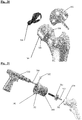
- the centre 10 of the acetabulum 12 was defined as the centre of a best-fit sphere fitted through points in the articulating part of the acetabular socket; i.e. the lunate surface.
- Markers, indicated on the drawings as A-Z, A1-Z1 etc, were then assigned to respective points around the whole of the acetabular rim 14 starting from the pubic end 16 and moving postero-superiorly.
- the acetabular notch 18 was also included in order to complete the cycle.
- a best fit plane was then fitted through all the rim points except the ones on the acetabular notch 18. This plane defined the acetabular plane, and the normal to it at the acetabular centre formed the normal vector D2.
- the angle subtended between this normal vector and the line joining the centre and a rim point defined the subtended angle for that particular point as shown in Figure 1 .
- the angular location of the rim points was measured in relation to an anterior rim landmark obtained after aligning the pelvis with the anterior pelvic plane (APP) defined by the two anterior superior iliac spines (ASIS) and the pubic tubercles. This provided a 'clock' position for each of the rim points.
- APP anterior pelvic plane
- ASIS anterior superior iliac spines
- pubic tubercles The anterior pelvic plane
- the x-axis pointed horizontally from left-to-right, the y-axis vertically upwards, and the z-axis posterior-to-anterior.
- the femoral head centre represented the hip centre and its coordinates (Cx, Cy, Cz) were measured.
- the pelvic horizontal dimension (Dx) was defined as the distance between the most lateral points F, G on the iliac crests, and its vertical dimension (Dy) was the distance between the highest point H on the iliac wing and the lowest point I on ischial tuberosity.
- the pelvic depth (Dz) was defined as the horizontal distance between the posterior superior iliac spine J and the ipsilateral anterior superior iliac spine D.
- the hip centre was determined by using the three orthogonal slices from the CT scan. Its x, y, and z coordinates were measured in relation to the reference coordinate system described above. The ratios of these coordinates to their corresponding pelvic dimensions (Cx/Dx, Cy/Dy, Cz/Dz) were measured. These ratios represent the horizontal, vertical, and posterior scaled offsets and have been termed herein HSO, VSO, and PSO respectively. The results were analysed for males and females. These are shown in Figure 18 and discussed below.
- CT scans of seven normal hips were analysed with 3D reconstruction software.
- the centre of the femoral head was then determined by fitting a sphere through a set of points on the femoral head surface.
- the angular position of the points on the head-neck junction was measured in relation to the piriform fossa reference point B.
- the 'clock' position angle (about the normal vector, in the head-neck junction plane) was measured for all the head-neck junction points, and a plot of the subtended angle as a function of this 'clock' position angle maps out the head-neck junction. This is shown in Figure 19 and discussed below.
- CT scans of 26 dry cadaveric femora were analysed using the same 3D reconstruction software.
- the centre A of the femoral head was defined as the centre of a best fit sphere through points on the head surface.
- a reference plane defined by a best fit plane through points on the flat part of the posterior surface of the femoral neck, was used.
- the point B was reproducibly acquired on the medial edge of the piriform fossa in the proximal femur.
- Another point P was identified at the highest point on the lesser trochanter after aligning the femur with the posterior neck reference plane.
- the mean of the points on the posterior neck plane was identified and the neck centre at the level of this mean point determined using the sagittal and coronal images.
- the neck centre was taken to be the point, on the perpendicular to the neck plane, half way between the mean point on the neck plane and the point R on the opposite side of the neck. This point will be referred to as the neck centre (NC).
- the vertical projection of the neck centre NC perpendicular to the line BP (joining the piriform fossa B and lesser trochanter P points (the base-of-neck line)) was then determined, inset from line BP, by the same offset as NC.
- This point is the base of neck centre, and the line joining this point and the neck centre defines the neck axis
- varus/valgus and ante-/retro-version relationships between the femoral head and neck can then measured.
- the origin of the proximal femoral frame of reference set to the piriform fossa point B the x,y,z-coordinates of the head centre can be calculated.
- the landmark acquisition and measurements were repeated by an independent observer in order to test the method's reliability.
- the acetabulum is a complex structure that cannot be simply represented by a hemisphere.
- the measurements described above found a repeatable pattern in its rim with identifiable peaks and troughs on the 2D profile as shown in Figure 17 .
- This figure shows profiles of some of the acetabula studied, based on plots of the subtended angle of individual rim points as a function of their 'clock' position angle. Deviations from a hemisphere can be seen in relation to a subtended angle of 90°, with a higher subtended angle indicating less than a hemisphere.
- the morphology of the acetabular rim takes into account certain bony and soft tissue anatomical considerations. An important element of those is the trough in the iliopubic interval which accommodates the ilio-psoas tendon. This cutout is crucial to avoid impingement in flexion. Superior coverage is evident by the iliac eminence, and when this is deficient as is the case in dysplasia. Moreover, the ischial prominence probably plays an important role in providing adequate coverage as in squatting, for instance. Reconstructive surgery according to some embodiments of the present invention aims to restore these features.
- Figure 17a shows similar plots of the acetabular rim shape for three different groups of hips of three respective types. In this case angles are measured from the bottom of the acetabular notch.
- the upper profile is of pincer-type hips, the middle profile of normal hips and the lower profile of cam-type hips. These plots are relevant as they show that, while the absolute height of the rim varies between different types of hip, the shape of the profile is essentially the same in all three types of hip. This means that a single implant can be designed for reconstruction of different types of hip.
- the scaled offsets of the hip centre vary predictably between genders, and for a given individual of known gender its coordinates can be derived from known pelvic landmarks.
- the scaled offsets for males and females are shown in Table 2. Table 2.
- the p values for the gender differences are also shown.
- HSO, VSO, and PSO are the horizontal, vertical, and posterior scaled offsets respectively.
- Figure 18 is a chart showing the distributions of the hip centre scaled offsets HSO, VSO, and PSO.
- the Femur The Femur:
- the femoral head is more than a hemisphere.
- the proportion of a sphere that it makes varies along its rim or junction with the femoral neck.
- a 2D profile was created by plotting the subtended angles of the head-neck junction points as a function of their 'clock' position angles on the head-neck junction and this is shown in Figure 19 .
- the position and orientation of the femoral head can be accurately defined relative to the femoral neck.
- a standardised and reproducible orientation of the femur can be achieved. From the origin at the piriform fossa, x-, y-, and z-coordinates for the femoral head centre can be measured, and the position of the head centre and orientation of the head using the head-neck junction plane, both relative to the neck axis, can be quantified in 3D space.
- a hip re-surfacing implant set comprises an acetabular cup 100 for resurfacing the acetabulum 104 and a femoral head implant 102 for resurfacing the head of the femur 106.
- the acetabular cup 100 is of substantially constant thickness and part spherical, with a rim 110 which is contoured so as to correspond in some ways to the rim of the acetabulum itself, but also so as to be simple to manufacture.
- the rim therefore is continuously curved and has raised and lowered regions forming an acetabular notch 112 an anterior pubic eminence 114, an ischial eminence 116 an iliac eminence 118 and an iliopubic interval 120.
- the acetabular notch has a depth of at least 15° and preferably at least 20° below the reference plane.
- the other recesses have a depth of at least 5° from the reference plane, and preferably at least 10°.
- the recesses have greater depth from the reference plane than the eminences have height.
- the iliac and ischial eminences therefore preferably rise to at least 5° above the reference plane, but at least to level with the reference plane, and the pubic eminence preferably rises at least to the reference plane, or at least to within 10° of the reference plane.
- the depth of each of the ilio-pubic and ilio -ischial intervals is preferably at least 10° and the depth of the depth of the acetabular notch is preferably at least 20°.
- the femoral head implant 102 comprises a part spherical cap 130, the outer surface of which is arranged to bear against the inner surface of the acetabular cup 100.
- the internal surface of the cap 130 can take a variety of shapes, but in this embodiment has a flat area 131a at the bottom, a part conical area 131b extending outwards from the flat bottom 131a, and a cylindrical part 131c extending up from the outer edge of the part conical area to the rim of the cap.
- a fixing post 132 projects from the centre of the flat bottom up and approximately through the centre of curvature of the bearing surface. The post 132 extends out beyond the rim of the cap 130.
- the rim of the cap 130 and hence also the external bearing surface, varies in height, with extended regions 134, 136 on the anterior and posterior sides, and between these, recesses on the medial and lateral sides.
- the subtended angle is about 120° to 125° at the extended regions and about 100 to 110° at the recesses. Therefore each of the extended regions subtends and angle of at least 10° greater than each of the recesses to either side of it, an in this case at least 15° greater.
- the depth of each of the recesses is preferably at least 10°, and may be at least 15°.
- This shape is arranged so as to replace only bone that is typically covered by articular cartilage and also to prevent soft tissue damage and to provide adequate clearance and protection for blood vessels, while providing sufficient bearing support in the anterior and posterior sides.
- the important part of the femoral head implant is the bearing surface.
- the internal surface and support can be designed in a number of different ways.
- the design of the acetabular cup is substantially simplified, and it includes an acetabular notch, which is symmetrical about its centre point, with the rest of the rim being flat.
- the cup is symmetrical about a point at approximately 290°. This has two advantages. Firstly it is simple to manufacture, and secondly because it is symmetrical, the cup is non-handed, and the same shape of cup can be used on both the left and right hips.
- the cup includes a symmetrical ilio-ischial interval centred on a point of symmetry at about 160° on the rim, iliac and ischial eminences located symmetrically on either side of the point of symmetry, an ilio-pubic interval and an acetabular notch also arranged symmetrically about the centre of the ilio-ischial interval, and a pubic eminence symmetrically located directly opposite the ilio-ischial interval.
- the eminences extend beyond a reference plane of the cup, which is the best fit plane through all points on the rim, and the intervals and notch dip below that plane.
- the femoral head implant as shown is not symmetrical, but in another embodiment, this implant can also be made symmetrical, with the anterior and posterior extensions 134, 136 being symmetrically placed on opposite sides of the rim and each being symmetrical about its own centre. Again this allows for the same implant to be used on both left and right hips.
- a complete set of implants will include a number of pairs of matching implants, the pairs being of different sizes to fit different patients. However, the shape of the different pairs is identical, the only difference being of scale.
- a machining tool for machining the femur to the correct shape to receive the femoral cap 102 comprises a cylindrical body 200 with a locating pin 202 aligned with its axis and projecting from its front end.
- a cutter 204 is supported on bearings 203 in the body 200 parallel to the locating pin 202 and offset from the location axis.
- the locating pin 202 has a cam 205 support coaxially around it, with a rearward facing cam surface 206, having a height that varies in the axial direction.
- the body 200 has a forward facing cam follower surface 208 formed within it which is arranged to contact the cam surface 206 and to cause the body 200 to move axially relative to the locating pin 202 as the body is rotated about the locating pin.
- Spikes 210 in the front of the front of the cam 205 are provided to secure the locating pin 202 in rotation with the femur.
- the cutter 204 is slidable axially in the body 200 and is supported in the bearings 203 so that it can be rotated to cut the femur. The forward movement of the cutter 204 through the body 200 is limited by a collar 204a on the cutter.
- a ratcheting lever 212 projects radially from a rear section 202a of the body 200 to enable a user to rotate the body 200 and cutter about the location pin 202.
- the rear end of the body 202 is closed by a cover 216 held in place by screws 218.
- a flexible gaiter 220 at the front end of the body 200 is arranged to seal the body against the femur.
- the body 202 is hollow and irrigation ports 222, 224 are provided in the rear section 202a.
- Irrigation passages 226 are formed between the rear body portion 202a and the main body portion 202b to connect a saline solution irrigation system, which can be connected to the ports 222, 224, to the interior of the body to irrigate the cutter 204. Ring seals 228 seal these passages from each other.
- the tool may further comprise a navigation device, such as an optical navigation device, to enable it to be orientated correctly relative to the bone.
- the head of the femur is first pre-machined to form a shallow conical surface 300 on its end and a bore 302 extending inwards from its end, approximately along the neck axis.
- the locating pin 202 is inserted into the bore 302 and the spikes 210 on the back of the cam 205 pushed into the machined surface 300 to fix the locating pin 202 and the cam 205 in rotation
- the body 200 is then placed over the location pin 202 and pushed forwards until the cam follower surface 208 in the body contacts the cam surface 206.
- a high speed drill 230 is connected to the cutter 204 and the cutter driven and pushed forwards through its bearings to machine the bone until the collar 204a on the cutter limits the axial forwards movement of the cutter 204.
- the body 202, cutter 204 and drill 300 are then rotated about the locating pin 202, while the cutter 204 is pushed forwards, so that the cutter is moved axially by virtue of the cam 205 to cut the femur to the correct shape to receive the femoral head implant 102.
- the cam surface 206 is shaped to correspond to the shape of the rim of the femoral head implant 102. This results in the head of the femur being cut so that it has a cylindrical portion 304 extending back from the top end of the femur.
- the bottom edge 306 of the cylindrical portion is contoured so as to be deeper on the anterior and posterior sides and shallower at the superior and inferior sides It is an advantage of this method that only the minimum amount of the femur is cut away to allow the femoral head implant 102 to be inserted.
- an insertion tool 400 for use with the acetabular cup 100 comprises a hollow shaft 402 with its rear end supported in a handle 404 and a flange 406 at its front end.
- a sliding rod 408 is located within the shaft 402 with its front end projecting from the front end of the shaft furthest from the handle, in the centre of the flange 406.
- An operating lever 410 is pivotably mounted on the shaft 402, and a drive link 412 is connected between the lever 410 and the sliding rod 408, to which it is connected by a pin 414 which extends through a slot down one side of the shaft 402. The drive link 412 and pin 414 therefore move the rod 408 along the shaft 402 as the lever 410 is pivoted on the shaft 402.
- the front end of the sliding rod 408 has a gripping device 416 on it.
- a resilient cup 418 for example of moulded elastomeric material, is placed over the front end of the tool, with its rim resting on the flange 406.
- a protuberance 420 in the centre of the inside surface of the cup 418 is arranged to be gripped by the gripping device 416.
- a groove 422 is formed extending around the cup, and an O-ring seal is located in this groove 422.
- a flange 423 is formed on its outer side, the front side 423a of which is contoured so as to match the contoured rim of the acetabular cup 100. This provides rotational location of the acetabular cup 100 on the tool 400.
- a navigational location device 424 is mounted on the shaft 402 which can be used to determine the location and orientation of the tool, and hence of the acetabular cup 100.
- the resilient cup 418 is placed inside the acetabular cup implant 102 so that the O-ring seals against its inner surface.
- the operating lever 410 is then moved backwards which pulls the sliding rod 408 backwards. This pulls the base of the resilient cup 418 away from the implant cup 100 creating a vacuum between them, so that the implant cup 100 can be picked up and moved with the tool.
- the exact position of the implant cup 100 can be monitored using the navigational device 424, and the implant cup moved to its desired position and then released using the operating lever.
- a surgical guidance system is used.
- This includes a processing system and associated memory in the form of a computer 500 running a guidance program.
- a bone location device 502 can be attached to a bone and is arranged to communicate its position and orientation via an optical or other tracking device 504 to the computer 500.
- This provides a reference position and orientation in real space.
- the femoral machining tool 508 is also provided with a tracking device 510 so that its position and orientation can be determined by the computer.
- the acetabular cup insertion tool 400 is also set up so that its navigation device 424 provides the tracking output whereby the computer 500 can determine its position and location.
- a CTN system (Acrobot Co Ltd of London UK) can be used which uses tracking arms to locate the tools and bone.
- the guidance program is arranged to use images of the pelvis and femur to enable a user to input reference locations on those bones, and from those reference positions to determine a desired position for the implants.
- the patient is scanned and images of the pelvis and the femur are analysed to locate the hip centre and determine the location and orientation of the acetabular plane in the pelvis relative to the reference position and orientation using the coordinate system of Figures 4 to 7 , which is fixed relative to the bone, and also the size of the acetabulum, for example as a mean radius.
- the location in the image of the landmark features of the bones, relative to which the target positions of the implants can be determined can be identified by a user using an input device such as a mouse.
- the computer processor can in some cases locate the landmark features in the images using image processing techniques. From these positions the size of the implants to be used is determined, and the desired position and orientation of the acetabular cup implant determined using chosen values for the horizontal, vertical and posterior scaled offsets.
- the scan images are used to locate the neck centre line, and head/neck junction plane on the femur using the method described above with reference to Figures 9 to 16 . From these, the desired position of the centre, and the orientation, of the femoral head implant, relative to the reference position in the frame of reference of the bone, can be chosen. It should be noted that the desired position of the head implant is determined relative to features of the femoral neck, so that wear of the femoral head will not affect the chosen position of the implant.
- the bone location device 502 is attached to the bone, which enables the computer 500 to determine the absolute position of the bone, and hence, from the images, which include the location device and hence the reference position, the absolute desired position and orientation of the implants.
- the machining tool is controlled by the surgeon, while the computer monitors its position and provides feedback to the surgeon via the screen 512 to guide him so that he can position the machining tool so as to machine the bone correctly to achieve the desired position and orientation of the implant.
- a cam guide 614 comprises a tubular portion 616 which is a sliding fit around the guide pin 610, with a head 618 at its front end.
- the head 618 has a flat annular front surface 619 arranged to locate against a corresponding annular surface 620 formed on the femoral head, and a rearward facing cam surface 622 on its rear side.
- the cam surface 622 is annular, extending around the guide pint 610, and varying in height, i.e. distance from the flat front surface 619.
- a radius block 624 comprises a short tubular portion 626 which is slidably mounted on the tubular portion 616 and has a cam follower 628 projecting axially from its front end and arranged to contact a point on the cam surface 622.
- the radius block further comprises a cutter support portion 630 which has a bore 632 through it parallel to the guide pin 610 in which a cutter 634 is supported.
- the cutter 634 is in the form of a long cylindrical bit with a cutting tip 636 at its front end and a cutting surface 638 extending around a cutting portion 640 which extends back from the front end.
- the cutter 634 is supported at a fixed distance from the guide pin 610 and can be rotated about the guide pin 610 to cut the femur.
- a semi-cylindrical cutter shield 642 is mounted on the radius block 624 and projects forward from it so as to cover the outside of the front part of the cutter 634.
- a collar 644 on the cutter limits its movement forward through the radius block, so that the cutter can be moved forward to a fully inserted position where it is just spaced from the front end of the cutter shield 642.
- the top surface of the femur is cut to form the flat surface 620, and the guide pin 610 is inserted into the femoral head so that it projects perpendicular to the flat surface 620.
- the cam 614 is then slid down over the guide pin 610, and orientated so that the cam surface 622 is correctly orientated relative to the bone.
- the cam guide is then pushed forward so that location pins 646 on its front end lock into the bone to secure the cam guide in position.
- the radius block 624 is then pushed forwards until the cam follower 628 locates on the cam surface 622.
- the radius block 624 is then rotated so that the sides of the femoral head are cut away to the desired depth, the depth of the cutting, and therefore the height of the bottom edge 625 of the cut-away portion 627 varying around the femoral head as dictated by the profile of the cam surface 622.
- a femoral implant 700 is similar to that of Figure 22 in that it has a part spherical outer surface 710 with an internal cavity 712 inside it arranged to fit over the cut part of the femoral head after it has been machined, for example using the machine tool of Figure 34 .
- the edge 711 of the part spherical outer surface will vary in height around its edge in the same way as the femoral implant of Figure 22 , but that is not shown in Figure 35 .
- the cavity 712 is generally cylindrical, having a curved internal surface 713 with its bottom end 714 closed and its top end 716 open to receive the machined part of the femoral head.
- one side 718 of the cavity is flat, with the cavity being partially filled in, so that the volume of the cavity is less than a fully cylindrical cavity. Therefore, even though the axis of the cylindrical part of the cavity is aligned with the centre of the part spherical outer surface, the wall 720 of the implant in the region of the flat side surface 718 of the cavity is thicker than the rest of the wall of the implant, which is constant around the curved side wall 713 of the cavity.
- the implant of Figure 35 can be used in cases where the femur is severely worn to such an extent that there is insufficient bone in place to be cut into a full cylinder to support the implant, when the implant is correctly positioned on the femur. With cam-type hip deformities, one side of the femur is extremely worn. In such cases the femur can be cut to leave a part cylindrical volume of bone to support the implant, but with one face, where insufficient bone was present to form a complete cylinder, cut away to correspond with the flat wall 718 of the cavity 712.
- a cutting guide 800 for use with the implant of Figure 35 comprises a part-tubular sleeve 810, with one end 812 contoured to fit against the contoured lower edge 625 of the cut-away portion of the femur.
- One side 814 of the guide is cut away leaving a gap 816 between two axially extending end faces 818.
- the end faces 818 are in a common plane which is parallel to, but offset from, the axis of the guide.
- the interior surface of the guide 800 is the same size and shape as the curved interior surface 713 of the implant 700, with the gap 816 having a width equal to that of the flat internal surface 718 of the implant 700.
- the cut portion of the bone may not be a complete cylinder if one side of the femoral head has been worn away to a level inside the radius at which the cutter cuts.
- the guide 800 is placed over the cut bone so that the gap 816 is aligned with the non-cylindrical part of the cut bone.
- the bone is then cut down to a flat plane level with the end faces 818 of the guide 800. This leaves a part cylindrical cut bone portion which corresponds to the shape of the cavity 712 in the implant.
- the implant can then be put in place over the cut bone portion, and the cavity in the implant will be completely filled with bone so that the implant is securely supported on the femur.
- the exact shape of the cavity in the implant can vary.
- a set of implants and guides could be used to accommodate different levels of wear on the femur, to maximize the amount of bone left in each case while ensuring that the implant cavity is completely filled with bone in each case.
- the cavity in the implant could be cylindrical, but offset from the centre of the part-spherical external bearing surface. This would still result in the wall of the implant varying in radial thickness around the cavity, for example around the side of the cavity at a fixed height above the bottom of the cavity.
- the implants will therefore have walls of different thicknesses. This allows an implant to be selected to match the size of the femoral head that is being resurfaced.
- an acetabular cup implant 900 is similar to that of Figures 21 to 23 , but in this case the wall 902 of the cup is much thicker. Although the wall thickness can vary, in this case it is greater than the radius of the part-spherical inner bearing surface 904. This means that the implant can be used with a femoral head implant with a bearing surface which has a much smaller radius of curvature than that of Figures 21 to 23 .
- the rim 906 of the cup is contoured in the same way as that of the embodiment of Figures 21 to 23 , with the inner and outer edges 908, 910 of the rim following the same contours so that the three eminences 912 and the three recesses or intervals 914 are present across the full width of the cup wall.
- the outer edge 920 of the rim 922 again follows the same anatomical contours with the same three eminences and intervals, but the inner edge 924 of the rim is flat and defines a circle.
- the height of the internal bearing surface 926 is therefore constant around its edge.
- the contoured shape of the rim 922 of the cup blends gradually from its outer edge 920 to its inner edge 924 with the height of the eminences and recesses gradually reducing from the outer edge 920 to the inner edge 924. This has the advantages of maximizing the bearing area of the internal bearing surface, reducing contact area stress and reducing the risk of dislocation.
- the inner edge 924 can have a degree of contouring that is not zero, but less than that of the outer edge 920.
- the inner edge 930 of the rim is not flat, but still contoured in a way that is different from the outer edge 932.
- the angular positioning of the contours is different at the inner edge 930 from the outer edge 930. This allows the outer edge 932 to be contoured so as to provide the best anatomical fit as with the embodiments described above, and the inner edge 930 to be contoured so as to maximize the range of movement of the femoral implant relative to the cup before impingement occurs between the side of the neck of the femoral component and the inner edge 930 of the rim of the cup.
- the inner edge 930 is flat around most of its circumference but has a single recess 934 cut away to reduce neck impingement in deep flexion.
- the contouring of the rim blends gradually between the outer edge 932 and the inner edge 930.
- the number and angular location of the recesses and eminences at the inner edge 930 can vary in a number of different ways independently of the contours of the outer edge 932.
- an acetabular cup implant 960 designed for use in such hips has an inner bearing surface 962 that is part spherical and of constant radius of curvature, but an outer surface 964 that comprises two main regions 965, 966 having different functions.
- the largest region 965 is a bone interface region arranged to be placed in contact with the bone of the pelvis when the implant is in place.
- the smaller region 966 is an extension region which extends along the superior edge of the outer surface 964, being widest at the highest point on the rim and tapering towards its anterior and posterior ends.
- the extension region 966 is arranged to encourage the growth of the pelvic bone at the rim of the acetabulum over it, so as to increase the strength of the acetabulum and the support it provides for the implant.
- This extension region 966 may have the same characteristics as the bone interface region 965, i.e. the same surface texture and radius of curvature, and may therefore comprise an extension of the bone interface region. However in some embodiments it has different characteristics. In some cases it may have a different radius of curvature from the bone interface region.
- the extension region 966 is smooth on the macro- and micro-scale, i.e. at a scale of several microns, e.g. 10 microns or above, having no surface features of that size. In some cases it may have no surface features which are larger than 1 micron. It is however rough on the nanometer scale, i.e. having surface features which are less than 1 micron in height. In some cases it may only have surface features which are 500nm in height or smaller.
- the bone interface region 965 which in this embodiment is rough on the scale greater than 1 micron, but could be rough on a scale of 10 microns, or 100 microns or on larger macro-scales to provide an interference fit with the bone.
- the bone interface region can be less rough, or rough only on a smaller scale, than the extension region.
Priority Applications (1)
| Application Number | Priority Date | Filing Date | Title |
|---|---|---|---|
| EP19187613.5A EP3695811B1 (fr) | 2008-11-05 | 2009-11-05 | Implant de resurfaçage de hanche |
Applications Claiming Priority (3)
| Application Number | Priority Date | Filing Date | Title |
|---|---|---|---|
| GBGB0820219.4A GB0820219D0 (en) | 2008-11-05 | 2008-11-05 | Hip resurfacing |
| EP09760565A EP2367496A2 (fr) | 2008-11-05 | 2009-11-05 | Resurfaçage de la hanche |
| PCT/GB2009/051488 WO2010052500A2 (fr) | 2008-11-05 | 2009-11-05 | Resurfaçage de la hanche |
Related Parent Applications (1)
| Application Number | Title | Priority Date | Filing Date |
|---|---|---|---|
| EP09760565A Division EP2367496A2 (fr) | 2008-11-05 | 2009-11-05 | Resurfaçage de la hanche |
Related Child Applications (1)
| Application Number | Title | Priority Date | Filing Date |
|---|---|---|---|
| EP19187613.5A Division EP3695811B1 (fr) | 2008-11-05 | 2009-11-05 | Implant de resurfaçage de hanche |
Publications (2)
| Publication Number | Publication Date |
|---|---|
| EP3192471A1 true EP3192471A1 (fr) | 2017-07-19 |
| EP3192471B1 EP3192471B1 (fr) | 2019-07-24 |
Family
ID=40138328
Family Applications (3)
| Application Number | Title | Priority Date | Filing Date |
|---|---|---|---|
| EP19187613.5A Active EP3695811B1 (fr) | 2008-11-05 | 2009-11-05 | Implant de resurfaçage de hanche |
| EP17153379.7A Active EP3192471B1 (fr) | 2008-11-05 | 2009-11-05 | Implant de resurfaçage de hanche |
| EP09760565A Withdrawn EP2367496A2 (fr) | 2008-11-05 | 2009-11-05 | Resurfaçage de la hanche |
Family Applications Before (1)
| Application Number | Title | Priority Date | Filing Date |
|---|---|---|---|
| EP19187613.5A Active EP3695811B1 (fr) | 2008-11-05 | 2009-11-05 | Implant de resurfaçage de hanche |
Family Applications After (1)
| Application Number | Title | Priority Date | Filing Date |
|---|---|---|---|
| EP09760565A Withdrawn EP2367496A2 (fr) | 2008-11-05 | 2009-11-05 | Resurfaçage de la hanche |
Country Status (8)
| Country | Link |
|---|---|
| US (1) | US9566159B2 (fr) |
| EP (3) | EP3695811B1 (fr) |
| JP (3) | JP2012507380A (fr) |
| CN (1) | CN102271610A (fr) |
| CA (2) | CA3046994C (fr) |
| ES (1) | ES2742475T3 (fr) |
| GB (1) | GB0820219D0 (fr) |
| WO (1) | WO2010052500A2 (fr) |
Families Citing this family (29)
| Publication number | Priority date | Publication date | Assignee | Title |
|---|---|---|---|---|
| BRPI1007988A2 (pt) | 2009-02-24 | 2016-03-01 | Smith & Nephew Inc | método e aparelho para cirurgias fai. |
| EP2575686B1 (fr) | 2010-06-03 | 2019-10-16 | Smith & Nephew, Inc. | Implants orthopédiques |
| GB2486020A (en) * | 2010-12-02 | 2012-06-06 | Biomet Uk Healthcare Ltd | Impaction tool for manipulating an implant |
| GB201021953D0 (en) * | 2010-12-24 | 2011-02-02 | Smith & Nephew | Medical device and method |
| WO2012103169A2 (fr) | 2011-01-25 | 2012-08-02 | Smith & Nephew, Inc. | Ciblage de sites d'exploitation |
| GB201102699D0 (en) * | 2011-02-16 | 2011-03-30 | Finsbury Dev Ltd | A surgical instrument |
| RU2013158108A (ru) | 2011-06-16 | 2015-07-27 | Смит Энд Нефью, Инк. | Хирургическое выравнивание с помощью ориентиров |
| WO2013052187A2 (fr) | 2011-06-27 | 2013-04-11 | Board Of Regents Of The University Of Nebraska | Système de suivi d'outil intégré et procédés de chirurgie assistée par ordinateur |
| US9498231B2 (en) | 2011-06-27 | 2016-11-22 | Board Of Regents Of The University Of Nebraska | On-board tool tracking system and methods of computer assisted surgery |
| US11911117B2 (en) | 2011-06-27 | 2024-02-27 | Board Of Regents Of The University Of Nebraska | On-board tool tracking system and methods of computer assisted surgery |
| DE102012101372A1 (de) * | 2012-02-21 | 2013-09-05 | Andrej Nowakowski | Hüftgelenk-Endoprothesensystem |
| BR112014021178A2 (pt) * | 2012-02-29 | 2017-06-27 | Smith & Nephew Inc | determinação de orientações anatômicas |
| EP2854701B1 (fr) * | 2012-06-05 | 2018-03-21 | Corin Limited | Guide avec moyen de génération d'indices de guidage |
| US20140031948A1 (en) | 2012-07-26 | 2014-01-30 | Patrick M. Birmingham | Method and device for joint replacement |
| CN102908214B (zh) * | 2012-09-21 | 2015-01-28 | 联合骨科器材股份有限公司 | 髋臼杯植入器 |
| KR20150065769A (ko) | 2012-09-27 | 2015-06-15 | 더 제너럴 하스피탈 코포레이션 | 정형외과용 임플란트를 위한 대퇴골두, 가동형 인서트, 비구 부재, 및 모듈식 정션 및 정형외과용 임플란트를 위한 대퇴골두, 가동형 인서트, 비구 부재, 및 모듈식 정션을 사용하는 방법 |
| US10105149B2 (en) | 2013-03-15 | 2018-10-23 | Board Of Regents Of The University Of Nebraska | On-board tool tracking system and methods of computer assisted surgery |
| CN104337572B (zh) * | 2013-07-24 | 2016-12-28 | 刘非 | 基于医学图像的定制化髋关节手术定位装置及配套假体 |
| EP3025305B1 (fr) * | 2013-07-25 | 2019-09-04 | Smith&Nephew, Inc. | Procédé de création de plan de résection chirurgicale pour traiter une déformation pathologique d'un os |
| US20150094728A1 (en) * | 2013-09-30 | 2015-04-02 | DePuy Synthes Products, LLC | Instrument for positioning a cup component of an orthopaedic joint prosthesis |
| CN103705317A (zh) * | 2013-12-27 | 2014-04-09 | 北京爱康宜诚医疗器材股份有限公司 | 组配式髋臼假体 |
| CN104306065B (zh) * | 2014-09-30 | 2016-11-30 | 创生医疗器械(中国)有限公司 | 髋臼对线装置及方法 |
| GB201521501D0 (en) * | 2015-12-07 | 2016-01-20 | Depuy Ireland | Apparatus and method for aligning an acetabular cup |
| US10918398B2 (en) | 2016-11-18 | 2021-02-16 | Stryker Corporation | Method and apparatus for treating a joint, including the treatment of cam-type femoroacetabular impingement in a hip joint and pincer-type femoroacetabular impingement in a hip joint |
| US10588756B2 (en) | 2017-03-31 | 2020-03-17 | DePuy Synthes Products, Inc. | System and method for implanting an acetabular prosthetic component |
| US11464569B2 (en) | 2018-01-29 | 2022-10-11 | Stryker Corporation | Systems and methods for pre-operative visualization of a joint |
| US10596011B2 (en) | 2018-01-31 | 2020-03-24 | Depuy Ireland Unlimited Company | Orthopaedic surgical instrument and method for positioning an acetabular prosthetic component |
| CN110811935A (zh) * | 2019-11-28 | 2020-02-21 | 中国人民解放军第四军医大学 | 一种3d打印半骨盆假体 |
| CN111494007B (zh) * | 2020-04-22 | 2020-12-18 | 北京长木谷医疗科技有限公司 | 假体投影的方法、装置及电子设备 |
Citations (2)
| Publication number | Priority date | Publication date | Assignee | Title |
|---|---|---|---|---|
| US20050060040A1 (en) * | 2003-09-15 | 2005-03-17 | Benoist Girard Sas | Prosthetic acetabular cup and prosthetic femoral joint incorporating such a cup |
| DE102006062618A1 (de) * | 2006-12-29 | 2008-07-03 | Plus Orthopedics Ag | Hüftgelenkprothese |
Family Cites Families (20)
| Publication number | Priority date | Publication date | Assignee | Title |
|---|---|---|---|---|
| GB1563334A (en) * | 1977-05-30 | 1980-03-26 | Charnley Surgical Inventions | Acetabular proshesis |
| SE449048B (sv) * | 1979-07-10 | 1987-04-06 | Charnley Surgical Inventions | Hoftledsprotes av plastmaterial avsedd for implantation i en hoftledpanna |
| US20040010319A1 (en) * | 1998-04-14 | 2004-01-15 | Osteoimplant Technology Inc. | Intrinsic stability in a total hip stem |
| US7695521B2 (en) * | 2001-05-01 | 2010-04-13 | Amedica Corporation | Hip prosthesis with monoblock ceramic acetabular cup |
| US7326253B2 (en) * | 2001-11-16 | 2008-02-05 | Depuy Products, Inc. | Prosthetic cup assembly having increased assembly congruency |
| ITUD20020037A1 (it) * | 2002-02-14 | 2003-08-14 | Lima Lto Spa | Protesi acetabolare dell'anca |
| DE60326608D1 (de) | 2002-10-04 | 2009-04-23 | Orthosoft Inc | Computergestützte hüftersatz chirurgie |
| US8034057B2 (en) * | 2002-11-07 | 2011-10-11 | Penenberg Brad L | Apparatus for, and method of, preparing for and inserting hip joint prosthesis using computer guidance |
| WO2005039456A1 (fr) * | 2003-09-27 | 2005-05-06 | Aesculap Ag & Co. Kg | Procede et dispositif pour determiner la mobilite d'une prothese de la hanche |
| FR2865928B1 (fr) * | 2004-02-10 | 2006-03-17 | Tornier Sa | Dispositif chirurgical d'implantation d'une prothese totale de hanche |
| KR100607401B1 (ko) * | 2004-05-13 | 2006-08-02 | 박형배 | 혈관보존형 대퇴골두 표면치환기구 |
| JP2006061504A (ja) * | 2004-08-27 | 2006-03-09 | Kyocera Corp | 人工関節 |
| ITMI20050038A1 (it) | 2005-01-17 | 2006-07-18 | Luca Massimo Carlo Pierannunzii | Coppa acetabolare perfezionata per artroprotesi d'anca |
| FR2898267B1 (fr) * | 2006-03-10 | 2008-12-26 | Michel Timoteo | Implant de re-surfacage de tete femorale et son ancillaire. |
| GB0610079D0 (en) | 2006-05-22 | 2006-06-28 | Finsbury Dev Ltd | Method & system |
| US20080004710A1 (en) * | 2006-06-30 | 2008-01-03 | Howmedica Osteonics Corp. | Femoral head resurfacing |
| WO2008090468A2 (fr) * | 2007-01-22 | 2008-07-31 | Zimmer, Gmbh | Implant et procédé de remplacement partiel de surfaces jointes |
| WO2008153964A1 (fr) * | 2007-06-07 | 2008-12-18 | Sam Hakki | Appareil et procédé de détermination d'axe central acétabulaire |
| US8267938B2 (en) * | 2007-11-01 | 2012-09-18 | Murphy Stephen B | Method and apparatus for determining acetabular component positioning |
| US8211184B2 (en) * | 2009-04-20 | 2012-07-03 | Michael D. Ries | Acetabular cup |
-
2008
- 2008-11-05 GB GBGB0820219.4A patent/GB0820219D0/en not_active Ceased
-
2009
- 2009-11-05 US US12/998,578 patent/US9566159B2/en active Active
- 2009-11-05 ES ES17153379T patent/ES2742475T3/es active Active
- 2009-11-05 WO PCT/GB2009/051488 patent/WO2010052500A2/fr active Application Filing
- 2009-11-05 EP EP19187613.5A patent/EP3695811B1/fr active Active
- 2009-11-05 JP JP2011535168A patent/JP2012507380A/ja active Pending
- 2009-11-05 EP EP17153379.7A patent/EP3192471B1/fr active Active
- 2009-11-05 EP EP09760565A patent/EP2367496A2/fr not_active Withdrawn
- 2009-11-05 CA CA3046994A patent/CA3046994C/fr active Active
- 2009-11-05 CA CA2742857A patent/CA2742857C/fr active Active
- 2009-11-05 CN CN2009801537872A patent/CN102271610A/zh active Pending
-
2014
- 2014-12-25 JP JP2014262246A patent/JP6525582B2/ja active Active
-
2017
- 2017-11-24 JP JP2017226353A patent/JP6472502B2/ja active Active
Patent Citations (2)
| Publication number | Priority date | Publication date | Assignee | Title |
|---|---|---|---|---|
| US20050060040A1 (en) * | 2003-09-15 | 2005-03-17 | Benoist Girard Sas | Prosthetic acetabular cup and prosthetic femoral joint incorporating such a cup |
| DE102006062618A1 (de) * | 2006-12-29 | 2008-07-03 | Plus Orthopedics Ag | Hüftgelenkprothese |
Also Published As
| Publication number | Publication date |
|---|---|
| EP2367496A2 (fr) | 2011-09-28 |
| EP3695811B1 (fr) | 2024-01-10 |
| US20110301654A1 (en) | 2011-12-08 |
| CA3046994C (fr) | 2021-10-12 |
| JP2015096209A (ja) | 2015-05-21 |
| CN102271610A (zh) | 2011-12-07 |
| JP2012507380A (ja) | 2012-03-29 |
| WO2010052500A2 (fr) | 2010-05-14 |
| ES2742475T3 (es) | 2020-02-14 |
| CA3046994A1 (fr) | 2010-05-14 |
| JP6472502B2 (ja) | 2019-02-20 |
| WO2010052500A3 (fr) | 2010-10-14 |
| JP6525582B2 (ja) | 2019-06-05 |
| US9566159B2 (en) | 2017-02-14 |
| EP3192471B1 (fr) | 2019-07-24 |
| CA2742857A1 (fr) | 2010-05-14 |
| GB0820219D0 (en) | 2008-12-10 |
| EP3695811A1 (fr) | 2020-08-19 |
| CA2742857C (fr) | 2019-08-13 |
| JP2018047292A (ja) | 2018-03-29 |
Similar Documents
| Publication | Publication Date | Title |
|---|---|---|
| EP3695811B1 (fr) | Implant de resurfaçage de hanche | |
| US6944518B2 (en) | Customized prosthesis and method of designing and manufacturing a customized prosthesis by utilizing computed tomography data | |
| US8175683B2 (en) | System and method of designing and manufacturing customized instrumentation for accurate implantation of prosthesis by utilizing computed tomography data | |
| US5007936A (en) | Surgical method for hip joint replacement | |
| US9439781B2 (en) | Patient-matched guides for orthopedic implants | |
| IL290081B (en) | A membrane for a medical connector, a medical connector and a method for assembling a medical connector | |
| Tang et al. | Sagittal pelvic mal‐rotation and positioning of the acetabular component in total hip arthroplasty: Three‐dimensional computer model analysis | |
| CA2810233A1 (fr) | Appareil et procede de positionnement d'implant de prothese | |
| CN107080607B (zh) | 一种基于3d打印技术的组配式髋臼假体定位装置 | |
| EP2836135B1 (fr) | Dispositif destiné à être utilisé pour faciliter l'alignement d'un composant acétabulaire | |
| US11931267B2 (en) | Joint implant extraction and placement system and localization device used therewith | |
| CN115607281B (zh) | 髋关节骨科手术导航系统 | |
| CN116421171A (zh) | 一种髋臼窝角度位置的测量、髋臼假体安装及其评估方法 | |
| US20200121476A1 (en) | Trial neck | |
| Zhang et al. | Comparison of anatomical shoulder prostheses and the proximal humeri of Chinese people | |
| US20230165595A1 (en) | Femoral head restoration | |
| Christoforakis et al. | An individualized approach for the implantation of a humeral prosthesis with the proper retroversion in fractures |
Legal Events
| Date | Code | Title | Description |
|---|---|---|---|
| PUAI | Public reference made under article 153(3) epc to a published international application that has entered the european phase |
Free format text: ORIGINAL CODE: 0009012 |
|
| STAA | Information on the status of an ep patent application or granted ep patent |
Free format text: STATUS: THE APPLICATION HAS BEEN PUBLISHED |
|
| AC | Divisional application: reference to earlier application |
Ref document number: 2367496 Country of ref document: EP Kind code of ref document: P |
|
| AK | Designated contracting states |
Kind code of ref document: A1 Designated state(s): AT BE BG CH CY CZ DE DK EE ES FI FR GB GR HR HU IE IS IT LI LT LU LV MC MK MT NL NO PL PT RO SE SI SK SM TR |
|
| STAA | Information on the status of an ep patent application or granted ep patent |
Free format text: STATUS: REQUEST FOR EXAMINATION WAS MADE |
|
| 17P | Request for examination filed |
Effective date: 20180119 |
|
| RBV | Designated contracting states (corrected) |
Designated state(s): AT BE BG CH CY CZ DE DK EE ES FI FR GB GR HR HU IE IS IT LI LT LU LV MC MK MT NL NO PL PT RO SE SI SK SM TR |
|
| STAA | Information on the status of an ep patent application or granted ep patent |
Free format text: STATUS: EXAMINATION IS IN PROGRESS |
|
| 17Q | First examination report despatched |
Effective date: 20180316 |
|
| REG | Reference to a national code |
Ref country code: DE Ref legal event code: R079 Ref document number: 602009059266 Country of ref document: DE Free format text: PREVIOUS MAIN CLASS: A61F0002340000 Ipc: A61F0002360000 |
|
| RIC1 | Information provided on ipc code assigned before grant |
Ipc: A61B 17/17 20060101ALI20181217BHEP Ipc: A61F 2/36 20060101AFI20181217BHEP Ipc: A61F 2/46 20060101ALI20181217BHEP Ipc: A61B 90/00 20160101ALI20181217BHEP Ipc: A61B 17/16 20060101ALI20181217BHEP Ipc: A61B 34/20 20160101ALI20181217BHEP |
|
| GRAP | Despatch of communication of intention to grant a patent |
Free format text: ORIGINAL CODE: EPIDOSNIGR1 |
|
| STAA | Information on the status of an ep patent application or granted ep patent |
Free format text: STATUS: GRANT OF PATENT IS INTENDED |
|
| INTG | Intention to grant announced |
Effective date: 20190130 |
|
| GRAS | Grant fee paid |
Free format text: ORIGINAL CODE: EPIDOSNIGR3 |
|
| GRAA | (expected) grant |
Free format text: ORIGINAL CODE: 0009210 |
|
| STAA | Information on the status of an ep patent application or granted ep patent |
Free format text: STATUS: THE PATENT HAS BEEN GRANTED |
|
| AC | Divisional application: reference to earlier application |
Ref document number: 2367496 Country of ref document: EP Kind code of ref document: P |
|
| AK | Designated contracting states |
Kind code of ref document: B1 Designated state(s): AT BE BG CH CY CZ DE DK EE ES FI FR GB GR HR HU IE IS IT LI LT LU LV MC MK MT NL NO PL PT RO SE SI SK SM TR |
|
| REG | Reference to a national code |
Ref country code: GB Ref legal event code: FG4D |
|
| REG | Reference to a national code |
Ref country code: CH Ref legal event code: EP |
|
| REG | Reference to a national code |
Ref country code: DE Ref legal event code: R096 Ref document number: 602009059266 Country of ref document: DE |
|
| REG | Reference to a national code |
Ref country code: AT Ref legal event code: REF Ref document number: 1157298 Country of ref document: AT Kind code of ref document: T Effective date: 20190815 |
|
| REG | Reference to a national code |
Ref country code: IE Ref legal event code: FG4D |
|
| RAP2 | Party data changed (patent owner data changed or rights of a patent transferred) |
Owner name: IP2IPO INNOVATIONS LIMITED |
|
| REG | Reference to a national code |
Ref country code: CH Ref legal event code: NV Representative=s name: TR-IP CONSULTING LLC, CH |
|
| REG | Reference to a national code |
Ref country code: NL Ref legal event code: MP Effective date: 20190724 |
|
| REG | Reference to a national code |
Ref country code: LT Ref legal event code: MG4D |
|
| REG | Reference to a national code |
Ref country code: BE Ref legal event code: HC Owner name: IP2IPO INNOVATIONS LIMITED; GB Free format text: DETAILS ASSIGNMENT: CHANGE OF OWNER(S), CHANGEMENT DE NOM DU PROPRIETAIRE; FORMER OWNER NAME: IMPERIAL INNOVATIONS LIMITED Effective date: 20191017 |
|
| REG | Reference to a national code |
Ref country code: AT Ref legal event code: MK05 Ref document number: 1157298 Country of ref document: AT Kind code of ref document: T Effective date: 20190724 |
|
| PG25 | Lapsed in a contracting state [announced via postgrant information from national office to epo] |
Ref country code: FI Free format text: LAPSE BECAUSE OF FAILURE TO SUBMIT A TRANSLATION OF THE DESCRIPTION OR TO PAY THE FEE WITHIN THE PRESCRIBED TIME-LIMIT Effective date: 20190724 Ref country code: NO Free format text: LAPSE BECAUSE OF FAILURE TO SUBMIT A TRANSLATION OF THE DESCRIPTION OR TO PAY THE FEE WITHIN THE PRESCRIBED TIME-LIMIT Effective date: 20191024 Ref country code: AT Free format text: LAPSE BECAUSE OF FAILURE TO SUBMIT A TRANSLATION OF THE DESCRIPTION OR TO PAY THE FEE WITHIN THE PRESCRIBED TIME-LIMIT Effective date: 20190724 Ref country code: PT Free format text: LAPSE BECAUSE OF FAILURE TO SUBMIT A TRANSLATION OF THE DESCRIPTION OR TO PAY THE FEE WITHIN THE PRESCRIBED TIME-LIMIT Effective date: 20191125 Ref country code: NL Free format text: LAPSE BECAUSE OF FAILURE TO SUBMIT A TRANSLATION OF THE DESCRIPTION OR TO PAY THE FEE WITHIN THE PRESCRIBED TIME-LIMIT Effective date: 20190724 Ref country code: SE Free format text: LAPSE BECAUSE OF FAILURE TO SUBMIT A TRANSLATION OF THE DESCRIPTION OR TO PAY THE FEE WITHIN THE PRESCRIBED TIME-LIMIT Effective date: 20190724 Ref country code: BG Free format text: LAPSE BECAUSE OF FAILURE TO SUBMIT A TRANSLATION OF THE DESCRIPTION OR TO PAY THE FEE WITHIN THE PRESCRIBED TIME-LIMIT Effective date: 20191024 Ref country code: LT Free format text: LAPSE BECAUSE OF FAILURE TO SUBMIT A TRANSLATION OF THE DESCRIPTION OR TO PAY THE FEE WITHIN THE PRESCRIBED TIME-LIMIT Effective date: 20190724 Ref country code: HR Free format text: LAPSE BECAUSE OF FAILURE TO SUBMIT A TRANSLATION OF THE DESCRIPTION OR TO PAY THE FEE WITHIN THE PRESCRIBED TIME-LIMIT Effective date: 20190724 |
|
| REG | Reference to a national code |
Ref country code: ES Ref legal event code: FG2A Ref document number: 2742475 Country of ref document: ES Kind code of ref document: T3 Effective date: 20200214 Ref country code: CH Ref legal event code: PCAR Free format text: NEW ADDRESS: ROUTE DU COUTSET 18, 1485 NUVILLY (CH) |
|
| PG25 | Lapsed in a contracting state [announced via postgrant information from national office to epo] |
Ref country code: GR Free format text: LAPSE BECAUSE OF FAILURE TO SUBMIT A TRANSLATION OF THE DESCRIPTION OR TO PAY THE FEE WITHIN THE PRESCRIBED TIME-LIMIT Effective date: 20191025 Ref country code: LV Free format text: LAPSE BECAUSE OF FAILURE TO SUBMIT A TRANSLATION OF THE DESCRIPTION OR TO PAY THE FEE WITHIN THE PRESCRIBED TIME-LIMIT Effective date: 20190724 Ref country code: IS Free format text: LAPSE BECAUSE OF FAILURE TO SUBMIT A TRANSLATION OF THE DESCRIPTION OR TO PAY THE FEE WITHIN THE PRESCRIBED TIME-LIMIT Effective date: 20191124 |
|
| PG25 | Lapsed in a contracting state [announced via postgrant information from national office to epo] |
Ref country code: TR Free format text: LAPSE BECAUSE OF FAILURE TO SUBMIT A TRANSLATION OF THE DESCRIPTION OR TO PAY THE FEE WITHIN THE PRESCRIBED TIME-LIMIT Effective date: 20190724 |
|
| PG25 | Lapsed in a contracting state [announced via postgrant information from national office to epo] |
Ref country code: PL Free format text: LAPSE BECAUSE OF FAILURE TO SUBMIT A TRANSLATION OF THE DESCRIPTION OR TO PAY THE FEE WITHIN THE PRESCRIBED TIME-LIMIT Effective date: 20190724 Ref country code: DK Free format text: LAPSE BECAUSE OF FAILURE TO SUBMIT A TRANSLATION OF THE DESCRIPTION OR TO PAY THE FEE WITHIN THE PRESCRIBED TIME-LIMIT Effective date: 20190724 Ref country code: EE Free format text: LAPSE BECAUSE OF FAILURE TO SUBMIT A TRANSLATION OF THE DESCRIPTION OR TO PAY THE FEE WITHIN THE PRESCRIBED TIME-LIMIT Effective date: 20190724 Ref country code: RO Free format text: LAPSE BECAUSE OF FAILURE TO SUBMIT A TRANSLATION OF THE DESCRIPTION OR TO PAY THE FEE WITHIN THE PRESCRIBED TIME-LIMIT Effective date: 20190724 |
|
| PG25 | Lapsed in a contracting state [announced via postgrant information from national office to epo] |
Ref country code: SK Free format text: LAPSE BECAUSE OF FAILURE TO SUBMIT A TRANSLATION OF THE DESCRIPTION OR TO PAY THE FEE WITHIN THE PRESCRIBED TIME-LIMIT Effective date: 20190724 Ref country code: CZ Free format text: LAPSE BECAUSE OF FAILURE TO SUBMIT A TRANSLATION OF THE DESCRIPTION OR TO PAY THE FEE WITHIN THE PRESCRIBED TIME-LIMIT Effective date: 20190724 Ref country code: SM Free format text: LAPSE BECAUSE OF FAILURE TO SUBMIT A TRANSLATION OF THE DESCRIPTION OR TO PAY THE FEE WITHIN THE PRESCRIBED TIME-LIMIT Effective date: 20190724 Ref country code: IS Free format text: LAPSE BECAUSE OF FAILURE TO SUBMIT A TRANSLATION OF THE DESCRIPTION OR TO PAY THE FEE WITHIN THE PRESCRIBED TIME-LIMIT Effective date: 20200224 |
|
| REG | Reference to a national code |
Ref country code: DE Ref legal event code: R097 Ref document number: 602009059266 Country of ref document: DE |
|
| PLBE | No opposition filed within time limit |
Free format text: ORIGINAL CODE: 0009261 |
|
| STAA | Information on the status of an ep patent application or granted ep patent |
Free format text: STATUS: NO OPPOSITION FILED WITHIN TIME LIMIT |
|
| PG2D | Information on lapse in contracting state deleted |
Ref country code: IS |
|
| PG25 | Lapsed in a contracting state [announced via postgrant information from national office to epo] |
Ref country code: MC Free format text: LAPSE BECAUSE OF FAILURE TO SUBMIT A TRANSLATION OF THE DESCRIPTION OR TO PAY THE FEE WITHIN THE PRESCRIBED TIME-LIMIT Effective date: 20190724 Ref country code: LU Free format text: LAPSE BECAUSE OF NON-PAYMENT OF DUE FEES Effective date: 20191105 |
|
| 26N | No opposition filed |
Effective date: 20200603 |
|
| PG25 | Lapsed in a contracting state [announced via postgrant information from national office to epo] |
Ref country code: SI Free format text: LAPSE BECAUSE OF FAILURE TO SUBMIT A TRANSLATION OF THE DESCRIPTION OR TO PAY THE FEE WITHIN THE PRESCRIBED TIME-LIMIT Effective date: 20190724 |
|
| REG | Reference to a national code |
Ref country code: DE Ref legal event code: R082 Ref document number: 602009059266 Country of ref document: DE Representative=s name: VENNER SHIPLEY GERMANY LLP, DE Ref country code: DE Ref legal event code: R082 Ref document number: 602009059266 Country of ref document: DE Representative=s name: VENNER SHIPLEY LLP, DE |
|
| PGFP | Annual fee paid to national office [announced via postgrant information from national office to epo] |
Ref country code: BE Payment date: 20201007 Year of fee payment: 12 |
|
| PG25 | Lapsed in a contracting state [announced via postgrant information from national office to epo] |
Ref country code: CY Free format text: LAPSE BECAUSE OF FAILURE TO SUBMIT A TRANSLATION OF THE DESCRIPTION OR TO PAY THE FEE WITHIN THE PRESCRIBED TIME-LIMIT Effective date: 20190724 |
|
| PG25 | Lapsed in a contracting state [announced via postgrant information from national office to epo] |
Ref country code: HU Free format text: LAPSE BECAUSE OF FAILURE TO SUBMIT A TRANSLATION OF THE DESCRIPTION OR TO PAY THE FEE WITHIN THE PRESCRIBED TIME-LIMIT; INVALID AB INITIO Effective date: 20091105 Ref country code: MT Free format text: LAPSE BECAUSE OF FAILURE TO SUBMIT A TRANSLATION OF THE DESCRIPTION OR TO PAY THE FEE WITHIN THE PRESCRIBED TIME-LIMIT Effective date: 20190724 |
|
| PG25 | Lapsed in a contracting state [announced via postgrant information from national office to epo] |
Ref country code: MK Free format text: LAPSE BECAUSE OF FAILURE TO SUBMIT A TRANSLATION OF THE DESCRIPTION OR TO PAY THE FEE WITHIN THE PRESCRIBED TIME-LIMIT Effective date: 20190724 |
|
| PG25 | Lapsed in a contracting state [announced via postgrant information from national office to epo] |
Ref country code: BE Free format text: LAPSE BECAUSE OF NON-PAYMENT OF DUE FEES Effective date: 20211130 |
|
| REG | Reference to a national code |
Ref country code: BE Ref legal event code: MM Effective date: 20211130 |
|
| P01 | Opt-out of the competence of the unified patent court (upc) registered |
Effective date: 20230526 |
|
| PGFP | Annual fee paid to national office [announced via postgrant information from national office to epo] |
Ref country code: GB Payment date: 20231010 Year of fee payment: 15 |
|
| PGFP | Annual fee paid to national office [announced via postgrant information from national office to epo] |
Ref country code: ES Payment date: 20231212 Year of fee payment: 15 |
|
| PGFP | Annual fee paid to national office [announced via postgrant information from national office to epo] |
Ref country code: IT Payment date: 20231002 Year of fee payment: 15 Ref country code: IE Payment date: 20231009 Year of fee payment: 15 Ref country code: FR Payment date: 20231011 Year of fee payment: 15 Ref country code: DE Payment date: 20231010 Year of fee payment: 15 Ref country code: CH Payment date: 20231201 Year of fee payment: 15 |