EP3192386A1 - Ski boot - Google Patents
Ski boot Download PDFInfo
- Publication number
- EP3192386A1 EP3192386A1 EP17151533.1A EP17151533A EP3192386A1 EP 3192386 A1 EP3192386 A1 EP 3192386A1 EP 17151533 A EP17151533 A EP 17151533A EP 3192386 A1 EP3192386 A1 EP 3192386A1
- Authority
- EP
- European Patent Office
- Prior art keywords
- shell
- ski boot
- casing
- user
- boot according
- Prior art date
- Legal status (The legal status is an assumption and is not a legal conclusion. Google has not performed a legal analysis and makes no representation as to the accuracy of the status listed.)
- Granted
Links
Images


Classifications
-
- A—HUMAN NECESSITIES
- A43—FOOTWEAR
- A43B—CHARACTERISTIC FEATURES OF FOOTWEAR; PARTS OF FOOTWEAR
- A43B5/00—Footwear for sporting purposes
- A43B5/04—Ski or like boots
- A43B5/0427—Ski or like boots characterised by type or construction details
- A43B5/0476—Front-entry skiboots
-
- A—HUMAN NECESSITIES
- A43—FOOTWEAR
- A43B—CHARACTERISTIC FEATURES OF FOOTWEAR; PARTS OF FOOTWEAR
- A43B5/00—Footwear for sporting purposes
- A43B5/04—Ski or like boots
-
- A—HUMAN NECESSITIES
- A43—FOOTWEAR
- A43B—CHARACTERISTIC FEATURES OF FOOTWEAR; PARTS OF FOOTWEAR
- A43B5/00—Footwear for sporting purposes
- A43B5/04—Ski or like boots
- A43B5/0405—Linings, paddings or insertions; Inner boots
-
- A—HUMAN NECESSITIES
- A43—FOOTWEAR
- A43B—CHARACTERISTIC FEATURES OF FOOTWEAR; PARTS OF FOOTWEAR
- A43B5/00—Footwear for sporting purposes
- A43B5/04—Ski or like boots
- A43B5/0411—Ski or like boots for cross-country
-
- A—HUMAN NECESSITIES
- A43—FOOTWEAR
- A43B—CHARACTERISTIC FEATURES OF FOOTWEAR; PARTS OF FOOTWEAR
- A43B5/00—Footwear for sporting purposes
- A43B5/04—Ski or like boots
- A43B5/0427—Ski or like boots characterised by type or construction details
- A43B5/0435—Adjustment of the boot to the foot
-
- A—HUMAN NECESSITIES
- A43—FOOTWEAR
- A43B—CHARACTERISTIC FEATURES OF FOOTWEAR; PARTS OF FOOTWEAR
- A43B5/00—Footwear for sporting purposes
- A43B5/04—Ski or like boots
- A43B5/0427—Ski or like boots characterised by type or construction details
- A43B5/0435—Adjustment of the boot to the foot
- A43B5/0443—Adjustment of the boot to the foot to the instep of the foot, e.g. metatarsals; Metatarsal clamping devices
-
- A—HUMAN NECESSITIES
- A43—FOOTWEAR
- A43B—CHARACTERISTIC FEATURES OF FOOTWEAR; PARTS OF FOOTWEAR
- A43B5/00—Footwear for sporting purposes
- A43B5/04—Ski or like boots
- A43B5/0427—Ski or like boots characterised by type or construction details
- A43B5/0435—Adjustment of the boot to the foot
- A43B5/0443—Adjustment of the boot to the foot to the instep of the foot, e.g. metatarsals; Metatarsal clamping devices
- A43B5/0447—Adjustment of the boot to the foot to the instep of the foot, e.g. metatarsals; Metatarsal clamping devices actuated by flexible means, e.g. cables, straps
-
- A—HUMAN NECESSITIES
- A43—FOOTWEAR
- A43B—CHARACTERISTIC FEATURES OF FOOTWEAR; PARTS OF FOOTWEAR
- A43B5/00—Footwear for sporting purposes
- A43B5/04—Ski or like boots
- A43B5/0427—Ski or like boots characterised by type or construction details
- A43B5/0435—Adjustment of the boot to the foot
- A43B5/045—Adjustment of the boot to the foot to the width of the foot
-
- A—HUMAN NECESSITIES
- A43—FOOTWEAR
- A43B—CHARACTERISTIC FEATURES OF FOOTWEAR; PARTS OF FOOTWEAR
- A43B5/00—Footwear for sporting purposes
- A43B5/04—Ski or like boots
- A43B5/0427—Ski or like boots characterised by type or construction details
- A43B5/047—Ski or like boots characterised by type or construction details provided with means to improve walking with the skiboot
-
- A—HUMAN NECESSITIES
- A43—FOOTWEAR
- A43B—CHARACTERISTIC FEATURES OF FOOTWEAR; PARTS OF FOOTWEAR
- A43B5/00—Footwear for sporting purposes
- A43B5/04—Ski or like boots
- A43B5/0486—Ski or like boots characterized by the material
- A43B5/049—Ski or like boots characterized by the material with an upper made of composite material, e.g. fibers or core embedded in a matrix
-
- A—HUMAN NECESSITIES
- A43—FOOTWEAR
- A43C—FASTENINGS OR ATTACHMENTS OF FOOTWEAR; LACES IN GENERAL
- A43C11/00—Other fastenings specially adapted for shoes
- A43C11/008—Combined fastenings, e.g. to accelerate undoing or fastening
-
- A—HUMAN NECESSITIES
- A43—FOOTWEAR
- A43C—FASTENINGS OR ATTACHMENTS OF FOOTWEAR; LACES IN GENERAL
- A43C11/00—Other fastenings specially adapted for shoes
- A43C11/12—Slide or glide fastenings
-
- A—HUMAN NECESSITIES
- A43—FOOTWEAR
- A43C—FASTENINGS OR ATTACHMENTS OF FOOTWEAR; LACES IN GENERAL
- A43C11/00—Other fastenings specially adapted for shoes
- A43C11/16—Fastenings secured by wire, bolts, or the like
- A43C11/165—Fastenings secured by wire, bolts, or the like characterised by a spool, reel or pulley for winding up cables, laces or straps by rotation
-
- A—HUMAN NECESSITIES
- A43—FOOTWEAR
- A43C—FASTENINGS OR ATTACHMENTS OF FOOTWEAR; LACES IN GENERAL
- A43C11/00—Other fastenings specially adapted for shoes
- A43C11/20—Fastenings with tightening devices mounted on the tongue
-
- Y—GENERAL TAGGING OF NEW TECHNOLOGICAL DEVELOPMENTS; GENERAL TAGGING OF CROSS-SECTIONAL TECHNOLOGIES SPANNING OVER SEVERAL SECTIONS OF THE IPC; TECHNICAL SUBJECTS COVERED BY FORMER USPC CROSS-REFERENCE ART COLLECTIONS [XRACs] AND DIGESTS
- Y10—TECHNICAL SUBJECTS COVERED BY FORMER USPC
- Y10T—TECHNICAL SUBJECTS COVERED BY FORMER US CLASSIFICATION
- Y10T24/00—Buckles, buttons, clasps, etc.
- Y10T24/21—Strap tighteners
- Y10T24/2183—Ski, boot, and shoe fasteners
Definitions
- the present invention relates to a ski boot.
- the present invention relates to a ski boot for ski mountaineering, use to which the flowing description will make explicit reference without thereby losing in generality.
- ski boots for ski mountaineering basically comprise: a rigid shell made of plastic or composite material, which is shaped so as to accommodate the foot of the user, and has the lower part specifically structured so as to be fixed to the back of a downhill ski or similar by means of a special ski binding device; a rigid cuff made of plastic or composite material, which is shaped so as to embrace the lower part of the leg of the user from the behind, and is hinged to the upper part of the shell so as to be able to rotate about a transversal reference axis which is substantially perpendicular to the vertical midplane of the boot, and is also locally substantially coincident with the articulation axis of the ankle; an upper oblong tongue usually made of plastic material, which is arranged resting on the upper part of the shell, outside of the shell, so as to cover the longitudinal slit which extends straddling the midplane of the boot, in the area of the shell above the instep; and an inner liner in soft, thermal-insulating
- ski boots comprise a shell closing mechanism and a cuff closing mechanism, both manually operated.
- the shell closing mechanism usually comprises: a manually-operated cable-winding winch which is rigidly fixed on the upper side of the tongue with the winch rotation axis locally substantially perpendicular to the surface of the tongue; a number of fairlead elements which are attached rigidly to the shell, on opposite sides of the longitudinal slit of the latter; and lastly a flexible cable made of metal material, which comes out of the cable-winding winch, slidingly engages in succession the various fairlead elements present on the shell passing alternately from one side of the shell longitudinal slit to the other above the tongue, and lastly returns back inside the cable-winding winch.
- the manufacturer of ski mountaineering boots must produce the composite-material shells in a larger number of sizes, with the increased costs that this entails.
- Aims of the present invention is to realise a shell closing system which overcomes the drawbacks described above, possibly without increasing the overall production costs of the ski boot.
- a ski boot as defined in Claim 1 and preferably, though not necessarily, in any of the dependent claims.
- reference number 1 denotes as a whole a ski boot which may be advantageously used to practise ski mountaineering.
- Ski boot 1 firstly comprises: a rigid shell 2 which is shaped so as to accommodate the user's foot and has the lower part specifically structured/designed to couple/ connect in a rigid and stable, though easily releasable manner, to a ski binding device (not shown) of known type which, in turn, is adapted to be rigidly fixed to the back of a downhill ski or similar; and a rigid cuff 3 which is shaped so as to enclose the lower part of the leg of the user, and is hinged to the upper part of shell 2 so as to be able to freely pivot about a transversal rotation axis A, which is locally substantially perpendicular to the vertical midplane of the ski boot and is also substantially coincident with the articulation axis of the user's ankle.
- a transversal rotation axis A which is locally substantially perpendicular to the vertical midplane of the ski boot and is also substantially coincident with the articulation axis of the user's ankle.
- the lower part of shell 2 is preferably provided with a front tip 5 and rear heel 6.
- the front tip 5 is preferably structured so as to be able to couple/connect in a stable, though easily releasable manner to the toe piece (not shown) of a ski binding device which, in turn, is firmly fixed to the back of a generic downhill ski or similar.
- the rear heel 6 instead is preferably structured so as to be able to couple/connect in a stable, though easily releasable manner to the heel piece (not shown) of a ski binding device which, in turn, is firmly fixed to the back of a generic downhill ski or similar.
- the front tip 5 of shell 2 is preferably structured so as to be able to couple/connect in a stable, though easily releasable manner to the toe piece of a ski-mountaineering binding device; whereas the rear heel 6 of shell 2 is preferably structured so as to be able to couple/connect in a stable, though easily releasable manner, to the heel piece of the same ski-mountaineering binding device.
- the lower part of shell 2 additionally has a threaded profile so as to allow the user to walk on snow and ice.
- the ski boot 1 moreover comprises an inner liner 4 with a soft and thermal-insulating structure, optionally of the thermoformable type, which is inserted into shell 2 and optionally also into cuff 3 preferably, though not necessarily in removable manner.
- the inner liner 4 is shaped so as to accommodate, cover and protect the user's foot substantially up to the ankle and optionally also the lower part of the user's leg roughly up to the top of the calf.
- shell 2 comprises a substantially basin-shaped, rigid casing 7 which is made of plastic or composite material and is designed substantially like a shoe so as to cover and protect the user's foot substantially up to the ankle; and preferably also a bottom sole 8 which is preferably made of vulcanized rubber or other elastomeric material with a high friction coefficient, and is firmly attached to the bottom wall of casing 7 preferably by glueing.
- casing 7 is preferably made of PEBAX (polyester-amide), Nylon (polyamide) or other similar plastic polymer.
- casing 7 might also be made of a composite material preferably made up of one or more overlapping layers of carbon fibres and/or glass fibres and/or aramid fibres, suitably interwoven and/ or superimposed to one another and embedded in a matrix of epoxy, phenolic or polyester resin, preferably of thermosetting type.
- shell 2 furthermore comprises a first metal-material insert 9, which is firmly embedded/ incorporated in the bottom wall of casing 7 at the front tip 5 of shell 2, and is structured so as to emerge outside of the casing 7 on opposite sides of the midplane of the boot, so as to be able to couple/connect in known manner to the toe piece (not shown) of the ski-mountaineering binding device; and optionally also a second metal-material insert (not visible in the figures) which is instead recessed into the casing 7 at the heel 6, and is structured so as to be able to couple/connect in a known manner to the heel piece (not shown) of the same ski-mountaineering binding device.
- a first metal-material insert 9 which is firmly embedded/ incorporated in the bottom wall of casing 7 at the front tip 5 of shell 2, and is structured so as to emerge outside of the casing 7 on opposite sides of the midplane of the boot, so as to be able to couple/connect in known manner to the toe piece (not shown) of the ski-mountaineering
- cuff 3 instead consists basically of a rigid shell made of plastic or composite material and which is substantially C-bent so as to cover the rear part of the user's leg, from the ankle substantially up to the height of the calf, and is additionally provided with two oblong lateral flaps 11 which extend forwards from opposite sides of the midplane of the boot, so as to embrace from behind the user's leg roughly at the height of the calf, and then overlap to one another at the front of the leg, thus forming a tubular structure that encloses the user's leg at height of the calf.
- Cuff 3 is preferably fixed in free rotatable manner to the upper part of shell 2, or rather of casing 7, by means of two connecting hinges 12 preferably made of metal and which are placed on the inner and outer side walls of shell 2 and of cuff 3, aligned along axis A, so as to allow the cuff 3 to freely rotate on the shell 2 both forwards and backwards, while always remaining on a reference plane perpendicular to axis A and substantially coinciding with the midplane of the ski boot.
- the rigid casing 7 preferably presents, on each side wall of shell 2, a long longitudinal stiffening rib 13 which has an arched or roughly L-formed shape, and extends along the side wall of shell 2 so as to connect the rear heel 6 to the front tip 5 preferably simultaneously intersecting the axis A, i.e. the seat accommodating the connecting hinge 12.
- ski boot 1 is also provided with shell closing means 14 and cuff closing means 15, both manually operated.
- the shell closing means 14 are structured so as to selectively close/tighten the shell 2, or rather the casing 7, against the user's foot to immobilize the user's foot inside the shell 2, or rather the inner liner 4.
- the cuff closing means 16 are structured so as to selectively close/tighten the upper part of the cuff 3 against the user's leg, so as to immobilize the user's leg inside the shell 3, or rather the inner liner 4.
- the upper part of casing 7 is provided with a main opening/ mouth 17 from which the user's leg comes out, and with an oblong-shaped, auxiliary longitudinal slit 18 that branches from the main opening 17 and extends towards the front tip 5 of shell 2 along the area of casing 7 lying above the instep, while remaining substantially astride the midplane of the boot.
- the shell closing means 14 are placed at the longitudinal slit 18, and comprise:
- the distal ends of flexible tabs 20 are structured so as to allow the flexible cable 23 to freely slide within the same tabs; while the winch-type cable-winding assembly 22 is structured so as to be able to selectively wind the flexible cable 23 inside itself, firmly block the flexible cable 23, and lastly unwind the flexible cable 23.
- the winch-type cable-winding assembly 22 is thus able to tighten and keep taut the flexible cable 23, thus forcing the flexible tabs 20 and, as much as possible, also the casing 7 to flex towards the floating body 19, i.e. towards the centre of the longitudinal slit 18, so as to immobilize the user's foot inside the shell 2, or rather the inner liner 4.
- the rigid floating body 19 has a preferably substantially plate-like structure, and the winch-type cable-winding assembly 22 is located on the upper face of the rigid floating body 19, preferably close to the main opening 17 of casing 7.
- the rigid floating body 19 is additionally oblong in shape, and extends substantially straddling the centerline of longitudinal slit 18, resting on the upper part of the inner liner 4 for its entire length.
- the rigid floating body 19 is additionally substantially saddle-shaped so as to follow/copy the profile of the upper part of inner liner 4 covering the instep of the user's foot.
- the rigid floating body 19 is preferably engaged in pass-through and free sliding manner by one or more sections of the flexible cable 23.
- the upper face of rigid floating body 19 is preferably provided with one or more cable-pass bridges 24 (two bridges 24 in this example) each of which is preferably located substantially straddling the midplane of the boot, and is engaged in a pass-through and free sliding manner by the flexible cable 23.
- the flexible cable 23 might also extend from side to side of the rigid floating body 19 grazing the upper face of the latter.
- the rigid floating body 19 could be passed over at the top by one or more sections of the flexible cable 23.
- the flexible tabs 20 are preferably arranged in pairs on opposite sides of the centerline of the longitudinal slit 18, and preferably project cantilevered beyond the edge of the casing 7 and towards the rigid floating body 19 while remaining locally skimmed over the casing 7 and/or the upper part of inner liner 4.
- each flexible tab 20 is preferably provided with a transversal through hole which is engaged in a pass-through and free sliding manner by a corresponding section of the flexible cable 23.
- Preferably flexible tabs 20 are additionally made of plastic material, and are preferably rigidly fixed to the casing 7, inside the same casing 7.
- proximal ends of the flexible tabs 20 are preferably rigidly attached to the inner surface of the casing 7.
- the proximal ends of the flexible tabs 20 are preferably rigidly attached to the lateral walls of casing 7 by rivets 25 or other mechanical attachment members.
- proximal ends of the flexible tabs 20 may also be snapped or heat-welded directly onto the lateral walls of the casing 7.
- the winch-type cable-winding assembly 22 and flexible cable 23 are components already widely known and used in the footwear industry, and do not require further explanations since they are extensively described and illustrated, for example, in the patent applications US19970917056 , WO1998US16314 , JP20000507254 , US20010956601 , US20010099566 , US19990337763 , JP20010519784 , WO2000US19440 , US19990388756 , US20010993296 , US20030459843 , US20050263253 , US20070841872 , US20070842009 , US20070841997 , US20070842013 , US20070842005 , WO2005US39273 and US20040623341 P. Documents to which direct reference is to be made for any further details on the structure and/or cable-winding assembly 22.
- winch-type cable-winding assembly 22 and flexible cable 23 are preferably made by the US company BOA TECHNOLOGY INC.
- the shell 2 moreover comprises a protective gaiter 28 roughly tubular in shape, which is preferably made of a waterproof and optionally stretch material, and is placed on the upper part of casing 7 so as to completely close/cover the longitudinal slit 18 of casing 7 and then extend upward aligned above the main opening 17 of casing 7, so as to surround and cover the ankle of the user and optionally the lower part of the leg of the user, preferably roughly up to the height of the calf.
- the gaiter 28 moreover extends up the user's leg while remaining below the cuff 3.
- the lower part of the gaiter 28 is preferably irremovably and/or fluid-tight attached to the upper part of casing 7, preferably by welding or gluing.
- the lower part of gaiter 28 is additionally suitable to at least partly cover the shell closing means 14.
- the lower part of gaiter 28 has an oblong flap completely covering/closing the longitudinal slit 18 of casing 7, and also extends above the rigid floating body 19, the flexible tabs 20, the flexible cable 23 and at least partially the winch-type cable-winding assembly 22.
- the winch-type cable-winding assembly 22 is preferably rigidly fixed onto the floating body 19 below the gaiter 28, and in addition projects cantilevered above the gaiter 28 engaging in pass-through manner a small, complementary-shaped auxiliary opening 29 specifically formed on the area of the gaiter 28 which lies immediately above the floating body 19.
- the shell 2 is preferably additionally provided with a longitudinal zipper 30 preferably of the watertight type, which extends along the gaiter 28, from the area above the instep up to the upper opening 31 of gaiter 28 preferably flanking the auxiliary opening 29, and is structured so as to allow easy and rapid opening of the gaiter 28 to allow/facilitate the insertion of the user's foot inside the inner shoe 4.
- a longitudinal zipper 30 preferably of the watertight type, which extends along the gaiter 28, from the area above the instep up to the upper opening 31 of gaiter 28 preferably flanking the auxiliary opening 29, and is structured so as to allow easy and rapid opening of the gaiter 28 to allow/facilitate the insertion of the user's foot inside the inner shoe 4.
- the cuff closing means 16 instead are at least partially located on cuff 3, and are selectively able to pull the two oblong side flaps 11 of cuff 3 one towards the other, so as to be able to tighten the upper part of cuff 3 onto the user's leg to immobilize the user's leg inside the ski boot 1, or rather the inner liner 4.
- the cuff closing means 16 preferably comprise:
- the ski boot 1 is lastly also provided with a manually-operated or automatic cuff locking device 35 which is preferably located straddling the shell 2 and the cuff 3 in the area above the heel of the ski boot 1, and is structured so as to be able, selectively and alternatively
- ski boot 1 Operation of ski boot 1 is easily inferred from the description above, and does not need further explanations.
- the tightening of flexible cable 23 forces the flexible tabs 20 to flex towards the floating body 19, i.e. towards the centre of the longitudinal slit 18, firmly pressing the foot of the user against the bottom of shell 2, or rather against the bottom of casing 7.
- the shell closing means 14 lend themselves to be used in conjunction with a casing 7 made of highly rigid composite material, because the capability to immobilize the foot of the user inside the shell 2, or rather the inner liner 4, is not affected, except to a minor extent, by the stiffness of casing 7.
- the flexible tabs 20 in fact allow to directly embrace the upper part of user's foot and therefore permit to more effectively immobilize the user's foot inside the shell 2, or rather the inner liner 4.
- flexible tabs 20 makes it possible to push/press the user's foot down against the bottom of the shell 2, or rather against the bottom of the basin-shaped casing 7, significantly improving the comfort of fit and the ability to transmit, during use, the forces to the skier.
- the particular structure of the shell closing means 14 makes it possible to eliminate the tongue that is traditionally placed to cover the longitudinal slit 18 of casing 7, allowing a small reduction in the overall weight of the ski boot.
- the flexible tabs 20 can be over-injected directly onto the body of casing 7 during the injection moulding process of the casing 7.
Landscapes
- Health & Medical Sciences (AREA)
- General Health & Medical Sciences (AREA)
- Physical Education & Sports Medicine (AREA)
- Chemical & Material Sciences (AREA)
- Engineering & Computer Science (AREA)
- Composite Materials (AREA)
- Materials Engineering (AREA)
- Footwear And Its Accessory, Manufacturing Method And Apparatuses (AREA)
Abstract
Description
- The present invention relates to a ski boot.
- More in detail, the present invention relates to a ski boot for ski mountaineering, use to which the flowing description will make explicit reference without thereby losing in generality.
- As is known, ski boots for ski mountaineering currently on the market basically comprise: a rigid shell made of plastic or composite material, which is shaped so as to accommodate the foot of the user, and has the lower part specifically structured so as to be fixed to the back of a downhill ski or similar by means of a special ski binding device; a rigid cuff made of plastic or composite material, which is shaped so as to embrace the lower part of the leg of the user from the behind, and is hinged to the upper part of the shell so as to be able to rotate about a transversal reference axis which is substantially perpendicular to the vertical midplane of the boot, and is also locally substantially coincident with the articulation axis of the ankle; an upper oblong tongue usually made of plastic material, which is arranged resting on the upper part of the shell, outside of the shell, so as to cover the longitudinal slit which extends straddling the midplane of the boot, in the area of the shell above the instep; and an inner liner in soft, thermal-insulating material, which is inserted inside the shell and the cuff, and is shaped so as to receive and protect both the foot and the lower part of the user's leg.
- In addition the above-mentioned ski boots comprise a shell closing mechanism and a cuff closing mechanism, both manually operated.
- In the more sophisticated models, the shell closing mechanism usually comprises: a manually-operated cable-winding winch which is rigidly fixed on the upper side of the tongue with the winch rotation axis locally substantially perpendicular to the surface of the tongue; a number of fairlead elements which are attached rigidly to the shell, on opposite sides of the longitudinal slit of the latter; and lastly a flexible cable made of metal material, which comes out of the cable-winding winch, slidingly engages in succession the various fairlead elements present on the shell passing alternately from one side of the shell longitudinal slit to the other above the tongue, and lastly returns back inside the cable-winding winch.
- Despite working excellently, experimental tests have shown that, when used in conjunction with a shell composed of one or more overlapping layers of carbon fibres embedded in the resin, the above-described winch lacing system has a very limited capability to tighten the shell onto the foot of the user so that the shape of the composite-material shell must be almost tailor-made for the user, with all the drawbacks that this entails.
- To better meet the market demands, the manufacturer of ski mountaineering boots must produce the composite-material shells in a larger number of sizes, with the increased costs that this entails.
- Aims of the present invention is to realise a shell closing system which overcomes the drawbacks described above, possibly without increasing the overall production costs of the ski boot.
- In compliance with the above aims, according to the present invention there is provided a ski boot as defined in
Claim 1 and preferably, though not necessarily, in any of the dependent claims. - The present invention will now be described with reference to the accompanying drawings, which illustrate a non-limiting embodiment thereof, in which:
-
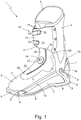
Figure 1 is a perspective view of a ski boot realized according to the teachings of the present invention; -
Figure 2 is a perspective and partially exploded view of the lower part of the ski boot shown inFigure 1 , with parts removed for clarity; while -
Figure 3 is an enlarged view of the shell of the ski boot shown inFigure 2 , with parts removed for clarity. - With reference to
Figures 1 ,2 and3 ,reference number 1 denotes as a whole a ski boot which may be advantageously used to practise ski mountaineering. -
Ski boot 1 firstly comprises: arigid shell 2 which is shaped so as to accommodate the user's foot and has the lower part specifically structured/designed to couple/ connect in a rigid and stable, though easily releasable manner, to a ski binding device (not shown) of known type which, in turn, is adapted to be rigidly fixed to the back of a downhill ski or similar; and arigid cuff 3 which is shaped so as to enclose the lower part of the leg of the user, and is hinged to the upper part ofshell 2 so as to be able to freely pivot about a transversal rotation axis A, which is locally substantially perpendicular to the vertical midplane of the ski boot and is also substantially coincident with the articulation axis of the user's ankle. - More in detail, the lower part of
shell 2 is preferably provided with afront tip 5 andrear heel 6. Thefront tip 5 is preferably structured so as to be able to couple/connect in a stable, though easily releasable manner to the toe piece (not shown) of a ski binding device which, in turn, is firmly fixed to the back of a generic downhill ski or similar. Therear heel 6 instead is preferably structured so as to be able to couple/connect in a stable, though easily releasable manner to the heel piece (not shown) of a ski binding device which, in turn, is firmly fixed to the back of a generic downhill ski or similar. - In the example shown, in particular, the
front tip 5 ofshell 2 is preferably structured so as to be able to couple/connect in a stable, though easily releasable manner to the toe piece of a ski-mountaineering binding device; whereas therear heel 6 ofshell 2 is preferably structured so as to be able to couple/connect in a stable, though easily releasable manner, to the heel piece of the same ski-mountaineering binding device. - Preferably, the lower part of
shell 2 additionally has a threaded profile so as to allow the user to walk on snow and ice. - In addition, the
ski boot 1 moreover comprises aninner liner 4 with a soft and thermal-insulating structure, optionally of the thermoformable type, which is inserted intoshell 2 and optionally also intocuff 3 preferably, though not necessarily in removable manner. Theinner liner 4 is shaped so as to accommodate, cover and protect the user's foot substantially up to the ankle and optionally also the lower part of the user's leg roughly up to the top of the calf. - With reference to
Figures 1 ,2 and3 ,shell 2 comprises a substantially basin-shaped,rigid casing 7 which is made of plastic or composite material and is designed substantially like a shoe so as to cover and protect the user's foot substantially up to the ankle; and preferably also a bottom sole 8 which is preferably made of vulcanized rubber or other elastomeric material with a high friction coefficient, and is firmly attached to the bottom wall ofcasing 7 preferably by glueing. - In the example shown, in particular,
casing 7 is preferably made of PEBAX (polyester-amide), Nylon (polyamide) or other similar plastic polymer. - In an alternative embodiment, however,
casing 7 might also be made of a composite material preferably made up of one or more overlapping layers of carbon fibres and/or glass fibres and/or aramid fibres, suitably interwoven and/ or superimposed to one another and embedded in a matrix of epoxy, phenolic or polyester resin, preferably of thermosetting type. - Preferably
shell 2 furthermore comprises a first metal-material insert 9, which is firmly embedded/ incorporated in the bottom wall ofcasing 7 at thefront tip 5 ofshell 2, and is structured so as to emerge outside of thecasing 7 on opposite sides of the midplane of the boot, so as to be able to couple/connect in known manner to the toe piece (not shown) of the ski-mountaineering binding device; and optionally also a second metal-material insert (not visible in the figures) which is instead recessed into thecasing 7 at theheel 6, and is structured so as to be able to couple/connect in a known manner to the heel piece (not shown) of the same ski-mountaineering binding device. - With reference to
Figure 1 , preferablycuff 3 instead consists basically of a rigid shell made of plastic or composite material and which is substantially C-bent so as to cover the rear part of the user's leg, from the ankle substantially up to the height of the calf, and is additionally provided with two oblonglateral flaps 11 which extend forwards from opposite sides of the midplane of the boot, so as to embrace from behind the user's leg roughly at the height of the calf, and then overlap to one another at the front of the leg, thus forming a tubular structure that encloses the user's leg at height of the calf. -
Cuff 3, furthermore, is preferably fixed in free rotatable manner to the upper part ofshell 2, or rather ofcasing 7, by means of two connectinghinges 12 preferably made of metal and which are placed on the inner and outer side walls ofshell 2 and ofcuff 3, aligned along axis A, so as to allow thecuff 3 to freely rotate on theshell 2 both forwards and backwards, while always remaining on a reference plane perpendicular to axis A and substantially coinciding with the midplane of the ski boot. - In the example shown, moreover, the
rigid casing 7 preferably presents, on each side wall ofshell 2, a long longitudinalstiffening rib 13 which has an arched or roughly L-formed shape, and extends along the side wall ofshell 2 so as to connect therear heel 6 to thefront tip 5 preferably simultaneously intersecting the axis A, i.e. the seat accommodating theconnecting hinge 12. - With reference to
Figures 1 ,2 and3 , in addition theski boot 1 is also provided with shell closing means 14 and cuff closing means 15, both manually operated. - The shell closing means 14 are structured so as to selectively close/tighten the
shell 2, or rather thecasing 7, against the user's foot to immobilize the user's foot inside theshell 2, or rather theinner liner 4. - The cuff closing means 16, instead, are structured so as to selectively close/tighten the upper part of the
cuff 3 against the user's leg, so as to immobilize the user's leg inside theshell 3, or rather theinner liner 4. - More in detail, with reference to
Figures 2 and3 , the upper part ofcasing 7 is provided with a main opening/mouth 17 from which the user's leg comes out, and with an oblong-shaped, auxiliarylongitudinal slit 18 that branches from themain opening 17 and extends towards thefront tip 5 ofshell 2 along the area ofcasing 7 lying above the instep, while remaining substantially astride the midplane of the boot. - The shell closing means 14 are placed at the
longitudinal slit 18, and comprise: - a rigid floating
body 19 which is preferably made of plastic or composite material and is suspended substantially at the centre of thelongitudinal slit 18 so as to extend like a saddle over the instep of foot of the user, preferably also resting against the upper part ofinner liner 4; - a plurality of flexible
oblong tabs 20, which are firmly secured to thecasing 7 around thelongitudinal slit 18, and cantilevered project into thelongitudinal slit 18 towards the rigid floatingbody 19, preferably while remaining locally skimmed over theinner liner 4 beneath; - a manually operated, winch-type cable-
winding assembly 22 which is rigidly fixed to the rigidfloating body 19, above the latter; and - a
flexible cable 23 preferably made of metal material and which comes out of the cable-winding assembly 22, engages in pass-through and free sliding manner and in succession the distal ends of the variousflexible tabs 20 moving alternately from one side of thefloating body 19 to the other, and preferably then returns back into the cable-winding assembly 22. - The distal ends of
flexible tabs 20 are structured so as to allow theflexible cable 23 to freely slide within the same tabs; while the winch-type cable-winding assembly 22 is structured so as to be able to selectively wind theflexible cable 23 inside itself, firmly block theflexible cable 23, and lastly unwind theflexible cable 23. - The winch-type cable-
winding assembly 22 is thus able to tighten and keep taut theflexible cable 23, thus forcing theflexible tabs 20 and, as much as possible, also thecasing 7 to flex towards thefloating body 19, i.e. towards the centre of thelongitudinal slit 18, so as to immobilize the user's foot inside theshell 2, or rather theinner liner 4. - With particular reference to
Figures 2 and3 , in the example shown, in particular, the rigidfloating body 19 has a preferably substantially plate-like structure, and the winch-type cable-winding assembly 22 is located on the upper face of the rigid floatingbody 19, preferably close to themain opening 17 ofcasing 7. - Preferably the rigid
floating body 19 is additionally oblong in shape, and extends substantially straddling the centerline oflongitudinal slit 18, resting on the upper part of theinner liner 4 for its entire length. Preferably the rigidfloating body 19 is additionally substantially saddle-shaped so as to follow/copy the profile of the upper part ofinner liner 4 covering the instep of the user's foot. - In addition, the rigid floating
body 19 is preferably engaged in pass-through and free sliding manner by one or more sections of theflexible cable 23. - More specifically the upper face of rigid floating
body 19 is preferably provided with one or more cable-pass bridges 24 (twobridges 24 in this example) each of which is preferably located substantially straddling the midplane of the boot, and is engaged in a pass-through and free sliding manner by theflexible cable 23. - In an alternative embodiment, however, the
flexible cable 23 might also extend from side to side of the rigidfloating body 19 grazing the upper face of the latter. - In other words, the rigid floating
body 19 could be passed over at the top by one or more sections of theflexible cable 23. - With particular reference to
Figure 3 , instead, theflexible tabs 20 are preferably arranged in pairs on opposite sides of the centerline of thelongitudinal slit 18, and preferably project cantilevered beyond the edge of thecasing 7 and towards the rigidfloating body 19 while remaining locally skimmed over thecasing 7 and/or the upper part ofinner liner 4. - In addition, the distal end of each
flexible tab 20 is preferably provided with a transversal through hole which is engaged in a pass-through and free sliding manner by a corresponding section of theflexible cable 23. - Preferably
flexible tabs 20 are additionally made of plastic material, and are preferably rigidly fixed to thecasing 7, inside thesame casing 7. - More specifically, the proximal ends of the
flexible tabs 20 are preferably rigidly attached to the inner surface of thecasing 7. - In the example shown, in particular, the proximal ends of the
flexible tabs 20 are preferably rigidly attached to the lateral walls ofcasing 7 byrivets 25 or other mechanical attachment members. - In an alternative embodiment, however, the proximal ends of the
flexible tabs 20 may also be snapped or heat-welded directly onto the lateral walls of thecasing 7. - The winch-type cable-
winding assembly 22 andflexible cable 23 are components already widely known and used in the footwear industry, and do not require further explanations since they are extensively described and illustrated, for example, in the patent applicationsUS19970917056 ,WO1998US16314 JP20000507254 US20010956601 ,US20010099566 ,US19990337763 ,JP20010519784 WO2000US19440 US19990388756 ,US20010993296 ,US20030459843 ,US20050263253 ,US20070841872 ,US20070842009 ,US20070841997 ,US20070842013 ,US20070842005 ,WO2005US39273 US20040623341 P. Documents to which direct reference is to be made for any further details on the structure and/or cable-winding assembly 22. - In the example shown, in particular, winch-type cable-
winding assembly 22 andflexible cable 23 are preferably made by the US company BOA TECHNOLOGY INC. - With reference to
Figures 1 and2 , preferably theshell 2 moreover comprises aprotective gaiter 28 roughly tubular in shape, which is preferably made of a waterproof and optionally stretch material, and is placed on the upper part ofcasing 7 so as to completely close/cover thelongitudinal slit 18 ofcasing 7 and then extend upward aligned above themain opening 17 ofcasing 7, so as to surround and cover the ankle of the user and optionally the lower part of the leg of the user, preferably roughly up to the height of the calf. Preferably thegaiter 28 moreover extends up the user's leg while remaining below thecuff 3. - More specifically, the lower part of the
gaiter 28 is preferably irremovably and/or fluid-tight attached to the upper part ofcasing 7, preferably by welding or gluing. - Preferably the lower part of
gaiter 28 is additionally suitable to at least partly cover the shell closing means 14. - In other words, with particular reference to
Figures 1 and2 , the lower part ofgaiter 28 has an oblong flap completely covering/closing thelongitudinal slit 18 ofcasing 7, and also extends above the rigidfloating body 19, theflexible tabs 20, theflexible cable 23 and at least partially the winch-type cable-winding assembly 22. - More specifically, the winch-type cable-
winding assembly 22 is preferably rigidly fixed onto thefloating body 19 below thegaiter 28, and in addition projects cantilevered above thegaiter 28 engaging in pass-through manner a small, complementary-shapedauxiliary opening 29 specifically formed on the area of thegaiter 28 which lies immediately above thefloating body 19. - With reference to
Figures 1 and2 , lastly theshell 2 is preferably additionally provided with alongitudinal zipper 30 preferably of the watertight type, which extends along thegaiter 28, from the area above the instep up to theupper opening 31 ofgaiter 28 preferably flanking theauxiliary opening 29, and is structured so as to allow easy and rapid opening of thegaiter 28 to allow/facilitate the insertion of the user's foot inside theinner shoe 4. - With reference to
Figure 1 , the cuff closing means 16 instead are at least partially located oncuff 3, and are selectively able to pull the twooblong side flaps 11 ofcuff 3 one towards the other, so as to be able to tighten the upper part ofcuff 3 onto the user's leg to immobilize the user's leg inside theski boot 1, or rather theinner liner 4. - In the example shown, in particular, the cuff closing means 16 preferably comprise:
- two cable-
return members 32, which are located on afirst side flap 11 ofcuff 3 vertically spaced one beside the other; - a tightening
cable 33, which has both ends firmly attached to thecuff 3, directly on or close to thesecond side flap 11 ofcuff 3, and extends towards thefirst side flap 11 roughly grazing the surface of thesecond side flap 11, so as to be able to reach and engage in free sliding manner and in succession the two cable-return members 32 following a substantially U-shaped path; and lastly - a manually-operated cable tightening device (not visible in the figure), which is coupled or couple-able to the tightening
cable 33 in a coupling point located along the central section of the tighteningcable 33, and is able to pull the central section of the cable transversely to the straight line joining the two cable-return members 32, so as to tighten the tighteningcable 33 and pull the two oblong side flaps 11 ofcuff 3 one towards the other. - With reference to
Figure 1 , preferably theski boot 1 is lastly also provided with a manually-operated or automaticcuff locking device 35 which is preferably located straddling theshell 2 and thecuff 3 in the area above the heel of theski boot 1, and is structured so as to be able, selectively and alternatively - to rigidly block the
cuff 3 to theshell 2 so as to prevent any swivel movement of thecuff 3 on theshell 2; or - fully unlock/release the
cuff 3 from theshell 2 so as to allow thecuff 3 to freely swing backwards and forwards on theshell 2 around axis A, while remaining on the midplane of the boot. - Operation of
ski boot 1 is easily inferred from the description above, and does not need further explanations. - As regards instead operation of the shell closing means 14, the tightening of
flexible cable 23 forces theflexible tabs 20 to flex towards the floatingbody 19, i.e. towards the centre of thelongitudinal slit 18, firmly pressing the foot of the user against the bottom ofshell 2, or rather against the bottom ofcasing 7. - The advantages resulting from the particular structure of the shell closing means 14 are remarkable.
- Firstly, the shell closing means 14 lend themselves to be used in conjunction with a
casing 7 made of highly rigid composite material, because the capability to immobilize the foot of the user inside theshell 2, or rather theinner liner 4, is not affected, except to a minor extent, by the stiffness ofcasing 7. - The
flexible tabs 20 in fact allow to directly embrace the upper part of user's foot and therefore permit to more effectively immobilize the user's foot inside theshell 2, or rather theinner liner 4. - In addition, the presence of
flexible tabs 20 makes it possible to push/press the user's foot down against the bottom of theshell 2, or rather against the bottom of the basin-shapedcasing 7, significantly improving the comfort of fit and the ability to transmit, during use, the forces to the skier. - Lastly, the particular structure of the shell closing means 14 makes it possible to eliminate the tongue that is traditionally placed to cover the
longitudinal slit 18 ofcasing 7, allowing a small reduction in the overall weight of the ski boot. - Finally, changes and variations may be clearly made to the
ski boot 1 described above without, however, departing from the scope of the present invention. - For example, the
flexible tabs 20 can be over-injected directly onto the body ofcasing 7 during the injection moulding process of thecasing 7.
Claims (15)
- Ski boot (1) comprising a rigid shell (2) which is shaped so as to accommodate the foot of the user, and has a lower part structured to couple with a ski binding device; a rigid cuff (3) which is shaped so as to surround the lower part of the leg of the user, and is pivotally jointed to the shell (2) thus to be able to pivot about a rotation axis (A) substantially perpendicular to the midplane of the boot, and shell closing means (14) adapted to selectively tighten the shell (2) on the foot of the user;
the shell (2) comprising a substantially basin-shaped casing (7) which is superiorly provided with a main opening (17) from which the leg of the user comes out, and with a longitudinal slit (18) that branches from said main opening (17) and extends along the casing (7) towards the front tip (5) of the shell (2);
the ski boot (1) being characterised in that the shell closing means (14) are located at the longitudinal slit (18) and comprise:- a rigid floating body (19) which is suspended substantially at the centre of the longitudinal slit (18) so as to extend like a saddle over the instep of foot of the user;- a plurality of flexible tabs (20) which are firmly secured to the casing (7) around the longitudinal slit (18) and cantilevered project into the longitudinal slit (18);- a winch-type cable-winding assembly (22) which is fixed on the rigid floating body (19); and- a flexible cable (23) that comes out of the cable-winding assembly (22) and engages, in pass-through and free sliding manner and in succession, the distal ends of the various flexible tabs (20) while moving alternately from one side to the other of the rigid floating body (19). - Ski boot according to claim 1, characterised in that the rigid floating body (19) is oblong in shape and extends substantially straddling the centerline of the longitudinal slit (18).
- Ski boot according to claim 1 or 2, characterised in that the rigid floating body (19) is engaged in pass-through and free sliding manner by one or more sections of the flexible cable (23), or is passed over by one or more sections of the flexible cable (23).
- Ski boot according to claim 1, 2 or 3, characterised in that the rigid floating body (19) has a substantially plate-like structure, and the winch-type cable-winding assembly (22) is located on the upper face of the rigid floating body (19).
- Ski boot according to any one of the preceding claims, characterised in that the flexible tabs (20) are arranged in pairs on opposite sides of the centerline of the longitudinal slit (18) of the casing (7).
- Ski boot according to any one of the preceding claims, characterised in that the distal ends of each flexible tab (20) is provided with a transversal through hole, which is engaged is pass-through and free sliding manner by a corresponding section of the flexible cable (23).
- Ski boot according to any one of the preceding claims, characterised in that the flexible tabs (20) are rigidly fixed to said casing (7) inside the same casing (7).
- Ski boot according to any one of the preceding claims, characterised in that the flexible tabs (20) are made of plastic material.
- Ski boot according to any one of the preceding claims, characterised by also comprising an inner liner (4) with a soft and thermal-insulating structure, which is inserted inside the shell (2) and is shaped so as to accommodate and protect at least the foot of the user; the rigid floating body (19) being arranged resting against the upper part of said inner liner (4); the flexible tabs (20) extending skimmed over the upper part of said inner liner (4).
- Ski boot according to any one of the preceding claims, characterised in that the shell (2) additionally comprises a protective gaiter (28) which is located on the upper part of the casing (7), so as to close the longitudinal slit (18) of the casing (7) and then extend upwards over the main opening (17) of the casing (7) thus to surround and cover the ankle of the user.
- Ski boot according claim 10, characterised in that said gaiter (28) moreover rises along the leg of the user remaining under the cuff (3).
- Ski boot according claim 10 or 11, characterised in that said gaiter (28) extends over the rigid floating body (19), the flexible tabs (20) and the flexible cable (23).
- Ski boot according to claim 12, characterised in that the winch-type cable-winding assembly (22) protrudes above said gaiter (28) engaging in pass-through manner an auxiliary opening (29) realized on the gaiter (28).
- Ski boot according to any one of claims 10 to 13, characterised in that the shell (2) additionally comprises a longitudinal zipper (30) that extends along said gaiter (28), from the area above the instep of the foot up to the upper opening (31) of the same gaiter (28).
- Ski boot according to any one of the preceding claims, characterised in that said casing (7) is made of plastic material or composite material.
Applications Claiming Priority (1)
| Application Number | Priority Date | Filing Date | Title |
|---|---|---|---|
| ITUB2016A000158A ITUB20160158A1 (en) | 2016-01-15 | 2016-01-15 | SKI BOOT |
Publications (2)
| Publication Number | Publication Date |
|---|---|
| EP3192386A1 true EP3192386A1 (en) | 2017-07-19 |
| EP3192386B1 EP3192386B1 (en) | 2018-09-19 |
Family
ID=55806639
Family Applications (1)
| Application Number | Title | Priority Date | Filing Date |
|---|---|---|---|
| EP17151533.1A Active EP3192386B1 (en) | 2016-01-15 | 2017-01-13 | Ski boot |
Country Status (4)
| Country | Link |
|---|---|
| US (1) | US10342284B2 (en) |
| EP (1) | EP3192386B1 (en) |
| AT (1) | AT16914U1 (en) |
| IT (1) | ITUB20160158A1 (en) |
Cited By (11)
| Publication number | Priority date | Publication date | Assignee | Title |
|---|---|---|---|---|
| EP3949785A1 (en) * | 2020-08-06 | 2022-02-09 | Calzaturificio S.C.A.R.P.A. S.p.A. | Ski boot |
| EP3949784A1 (en) * | 2020-08-06 | 2022-02-09 | Calzaturificio S.C.A.R.P.A. S.p.A. | Ski-boot |
| EP4014781A1 (en) | 2020-12-18 | 2022-06-22 | Salomon S.A.S. | Ski boot and tightening system |
| WO2023126907A1 (en) * | 2022-01-03 | 2023-07-06 | Puma SE | Article of footwear having a closure system |
| IT202200006998A1 (en) * | 2022-04-08 | 2023-10-08 | Ober Alp Spa | Sports shoe equipped with a perfected tongue |
| WO2023220181A1 (en) * | 2022-05-11 | 2023-11-16 | Boa Technology Inc. | Tightening system for ski boots |
| IT202200024597A1 (en) * | 2022-12-01 | 2024-06-01 | Securesi Srl | LACING SYSTEM OF THE INNER BOOT OF A SKI BOOT |
| FR3146050A1 (en) | 2023-02-28 | 2024-08-30 | Salomon S.A.S. | Ski boot and tightening device |
| EP4255247A4 (en) * | 2020-12-04 | 2024-10-23 | Boa Technology Inc. | COIL BASED CLOSURE DEVICE |
| US12144401B2 (en) | 2013-06-05 | 2024-11-19 | Boa Technology, Inc. | Integrated closure device components and methods |
| EP4732701A1 (en) | 2024-10-24 | 2026-04-29 | Calzaturificio S.C.A.R.P.A. S.p.A. | Cross-reference to related patent applications |
Families Citing this family (8)
| Publication number | Priority date | Publication date | Assignee | Title |
|---|---|---|---|---|
| US10130138B2 (en) * | 2016-01-22 | 2018-11-20 | Apex Sports Group, Llc | Exoskeletal boot |
| US10398191B2 (en) * | 2017-05-04 | 2019-09-03 | Carl Cox | Ski boot assembly |
| EP4678055A3 (en) * | 2019-02-01 | 2026-04-15 | Boa Technology, Inc. | Reel based closure devices for tightening a ski boot |
| JP2023508936A (en) * | 2019-12-31 | 2023-03-06 | ボア テクノロジー,インコーポレイテッド | Clamping device for clamping articles |
| USD971562S1 (en) * | 2020-08-31 | 2022-12-06 | Boa Technology Inc. | Ski boot having multiple reel based closure systems |
| IT202100007082A1 (en) * | 2021-03-24 | 2022-09-24 | Tecnica Group Spa | SKI BOOT, PARTICULARLY ALPINE SKI BOOT |
| USD1080182S1 (en) * | 2022-08-05 | 2025-06-24 | Wolverine Outdoors, Inc. | Lacing component |
| USD1068221S1 (en) * | 2023-10-05 | 2025-04-01 | suxHess Hess | Ski shoe |
Citations (13)
| Publication number | Priority date | Publication date | Assignee | Title |
|---|---|---|---|---|
| FR2734690A1 (en) * | 1995-05-30 | 1996-12-06 | Rossignol Sa | Boot for cross country skiing |
| EP0783844A2 (en) * | 1996-01-11 | 1997-07-16 | Ryusyo Industrial Co., Ltd. | Three-piece type ski boot |
| WO1999009850A1 (en) | 1997-08-22 | 1999-03-04 | Hammerslag Gary R | Footwear lacing system |
| JP2000507254A (en) | 1996-03-27 | 2000-06-13 | スミスクライン・ビーチャム・パブリック・リミテッド・カンパニー | Azaspiro derivative |
| WO2001015559A1 (en) | 1999-09-02 | 2001-03-08 | Boa Technology, Inc. | Footwear lacing system |
| JP2001519784A (en) | 1997-03-20 | 2001-10-23 | エンゾン,インコーポレーテッド | Non-antigenic branched polymer conjugate |
| US20020095750A1 (en) | 1997-08-22 | 2002-07-25 | Hammerslag Gary R. | Footwear lacing system |
| US20030204938A1 (en) | 1997-08-22 | 2003-11-06 | Hammerslag Gary R. | Footwear lacing system |
| US20040226190A1 (en) * | 2003-03-12 | 2004-11-18 | Goodwell International Ltd. | Laced boot |
| WO2006050266A2 (en) | 2004-10-29 | 2006-05-11 | Boa Technology, Inc. | Reel based closure system |
| US20060156517A1 (en) | 1997-08-22 | 2006-07-20 | Hammerslag Gary R | Reel based closure system |
| US20080060167A1 (en) | 1997-08-22 | 2008-03-13 | Hammerslag Gary R | Reel based closure system |
| WO2015038946A1 (en) * | 2013-09-13 | 2015-03-19 | K-2 Corporation | Sports boot with articulating lace guide |
Family Cites Families (13)
| Publication number | Priority date | Publication date | Assignee | Title |
|---|---|---|---|---|
| IT1221432B (en) * | 1988-03-22 | 1990-07-06 | Nordica Spa | PIDE LOCKING DEVICE, PARTICULARLY FOR SKI BOOTS |
| US5177882A (en) * | 1989-06-03 | 1993-01-12 | Puma Ag Rudolf Dassler Sport | Shoe with a central fastener |
| US5177884A (en) * | 1989-09-07 | 1993-01-12 | Salomon S.A. | Cross-country ski shoe |
| DE4404911C2 (en) * | 1994-02-16 | 1997-10-02 | Georg Dr Ahlbaeumer | Shoe, especially sports shoe or orthopedic stocking, with ankle stabilization |
| ITTV20010050A1 (en) * | 2001-04-23 | 2002-10-23 | Tecnica Spa | ARTICULATED REINFORCEMENT STRUCTURE AND FOOTWEAR EQUIPPED WITH SUCH STRUCTURE |
| DE10208853C1 (en) * | 2002-03-01 | 2003-06-26 | Goodwell Int Ltd | Lace up snow board boot has tongues separated by spacer tubes to allow individual tensioning of different parts of lace |
| US7082701B2 (en) * | 2004-01-23 | 2006-08-01 | Vans, Inc. | Footwear variable tension lacing systems |
| AT501443B1 (en) * | 2005-02-04 | 2007-03-15 | Atomic Austria Gmbh | SPORTS SHOE FOR RUNNING OR SHIELDING |
| FR2922416B1 (en) * | 2007-10-23 | 2010-02-19 | Salomon Sa | IMPROVED ROD TIGHTENING SHOE |
| CN104981174B (en) * | 2012-12-14 | 2017-07-18 | 范斯公司 | Clamping system for footwear |
| KR20260030757A (en) * | 2013-04-01 | 2026-03-06 | 보아 테크놀러지, 인크. | Methods and devices for retrofitting footwear to include a reel based closure system |
| ITTV20130204A1 (en) * | 2013-12-06 | 2015-06-07 | Scarpa Calzaturificio Spa | SKI BOOT |
| WO2018080581A1 (en) * | 2016-10-26 | 2018-05-03 | Nike Innovate C.V. | Deformable lace guides for automated footwear platform |
-
2016
- 2016-01-15 IT ITUB2016A000158A patent/ITUB20160158A1/en unknown
-
2017
- 2017-01-13 EP EP17151533.1A patent/EP3192386B1/en active Active
- 2017-01-13 US US15/405,629 patent/US10342284B2/en active Active
- 2017-01-13 AT ATGM50155/2019U patent/AT16914U1/en unknown
Patent Citations (20)
| Publication number | Priority date | Publication date | Assignee | Title |
|---|---|---|---|---|
| FR2734690A1 (en) * | 1995-05-30 | 1996-12-06 | Rossignol Sa | Boot for cross country skiing |
| EP0783844A2 (en) * | 1996-01-11 | 1997-07-16 | Ryusyo Industrial Co., Ltd. | Three-piece type ski boot |
| JP2000507254A (en) | 1996-03-27 | 2000-06-13 | スミスクライン・ビーチャム・パブリック・リミテッド・カンパニー | Azaspiro derivative |
| JP2001519784A (en) | 1997-03-20 | 2001-10-23 | エンゾン,インコーポレーテッド | Non-antigenic branched polymer conjugate |
| US20080060168A1 (en) | 1997-08-22 | 2008-03-13 | Hammerslag Gary R | Reel based closure system |
| US20080060167A1 (en) | 1997-08-22 | 2008-03-13 | Hammerslag Gary R | Reel based closure system |
| US6202953B1 (en) | 1997-08-22 | 2001-03-20 | Gary R. Hammerslag | Footwear lacing system |
| US6289558B1 (en) | 1997-08-22 | 2001-09-18 | Boa Technology, Inc. | Footwear lacing system |
| US5934599A (en) | 1997-08-22 | 1999-08-10 | Hammerslag; Gary R. | Footwear lacing system |
| US20020095750A1 (en) | 1997-08-22 | 2002-07-25 | Hammerslag Gary R. | Footwear lacing system |
| US20030204938A1 (en) | 1997-08-22 | 2003-11-06 | Hammerslag Gary R. | Footwear lacing system |
| US20080083135A1 (en) | 1997-08-22 | 2008-04-10 | Hammerslag Gary R | Reel based closure system |
| US20080066346A1 (en) | 1997-08-22 | 2008-03-20 | Hammerslag Gary R | Reel based closure system |
| US20060156517A1 (en) | 1997-08-22 | 2006-07-20 | Hammerslag Gary R | Reel based closure system |
| US20080066345A1 (en) | 1997-08-22 | 2008-03-20 | Hammerslag Gary R | Reel based closure system |
| WO1999009850A1 (en) | 1997-08-22 | 1999-03-04 | Hammerslag Gary R | Footwear lacing system |
| WO2001015559A1 (en) | 1999-09-02 | 2001-03-08 | Boa Technology, Inc. | Footwear lacing system |
| US20040226190A1 (en) * | 2003-03-12 | 2004-11-18 | Goodwell International Ltd. | Laced boot |
| WO2006050266A2 (en) | 2004-10-29 | 2006-05-11 | Boa Technology, Inc. | Reel based closure system |
| WO2015038946A1 (en) * | 2013-09-13 | 2015-03-19 | K-2 Corporation | Sports boot with articulating lace guide |
Cited By (15)
| Publication number | Priority date | Publication date | Assignee | Title |
|---|---|---|---|---|
| US12144401B2 (en) | 2013-06-05 | 2024-11-19 | Boa Technology, Inc. | Integrated closure device components and methods |
| EP3949784A1 (en) * | 2020-08-06 | 2022-02-09 | Calzaturificio S.C.A.R.P.A. S.p.A. | Ski-boot |
| EP3949785A1 (en) * | 2020-08-06 | 2022-02-09 | Calzaturificio S.C.A.R.P.A. S.p.A. | Ski boot |
| EP4255247A4 (en) * | 2020-12-04 | 2024-10-23 | Boa Technology Inc. | COIL BASED CLOSURE DEVICE |
| EP4014781A1 (en) | 2020-12-18 | 2022-06-22 | Salomon S.A.S. | Ski boot and tightening system |
| FR3117744A1 (en) | 2020-12-18 | 2022-06-24 | Salomon S.A.S | Ski boot and clamping device |
| WO2023126907A1 (en) * | 2022-01-03 | 2023-07-06 | Puma SE | Article of footwear having a closure system |
| US12458112B2 (en) | 2022-01-03 | 2025-11-04 | Puma SE | Article of footwear having a closure system |
| EP4257000A1 (en) * | 2022-04-08 | 2023-10-11 | OBER ALP S.p.A. | Sport shoe provided with an improved tongue |
| IT202200006998A1 (en) * | 2022-04-08 | 2023-10-08 | Ober Alp Spa | Sports shoe equipped with a perfected tongue |
| WO2023220181A1 (en) * | 2022-05-11 | 2023-11-16 | Boa Technology Inc. | Tightening system for ski boots |
| IT202200024597A1 (en) * | 2022-12-01 | 2024-06-01 | Securesi Srl | LACING SYSTEM OF THE INNER BOOT OF A SKI BOOT |
| FR3146050A1 (en) | 2023-02-28 | 2024-08-30 | Salomon S.A.S. | Ski boot and tightening device |
| EP4424198A1 (en) | 2023-02-28 | 2024-09-04 | Salomon S.A.S. | Ski boot and tightening device |
| EP4732701A1 (en) | 2024-10-24 | 2026-04-29 | Calzaturificio S.C.A.R.P.A. S.p.A. | Cross-reference to related patent applications |
Also Published As
| Publication number | Publication date |
|---|---|
| AT16914U1 (en) | 2020-11-15 |
| ITUB20160158A1 (en) | 2017-07-15 |
| US20170202297A1 (en) | 2017-07-20 |
| US10342284B2 (en) | 2019-07-09 |
| EP3192386B1 (en) | 2018-09-19 |
Similar Documents
| Publication | Publication Date | Title |
|---|---|---|
| EP3192386B1 (en) | Ski boot | |
| EP3725175B1 (en) | Ski boot | |
| EP3266327B1 (en) | Ski boot | |
| US5177882A (en) | Shoe with a central fastener | |
| EP2931076B1 (en) | Footwear retention systems | |
| JP6014146B2 (en) | Sports boots | |
| US5992872A (en) | Ski boot designed for use with parabolic alpine skis | |
| US12137772B2 (en) | Ski boot | |
| IE914151A1 (en) | Shoe with a central fastener | |
| JPH0654927A (en) | Foot fin for switching | |
| US10117477B2 (en) | Sports boot | |
| US20130091737A1 (en) | Footwear with improved upper | |
| US4757621A (en) | Ski boot | |
| EP3949784B1 (en) | Ski-boot | |
| EP4062788B1 (en) | Ski boot | |
| EP3175730B1 (en) | Ski boot | |
| EP3175731B1 (en) | Ski boot | |
| EP3949785B1 (en) | Ski boot | |
| EP3053469B1 (en) | A ski boot | |
| EP3130245B1 (en) | Ski boot | |
| IT202100006977A1 (en) | SKI BOOT | |
| EP4732701A1 (en) | Cross-reference to related patent applications | |
| EP4527231A1 (en) | Ski boot | |
| IT202100010148A1 (en) | SKI BOOT | |
| WO2002094048A1 (en) | Articulated ski boot |
Legal Events
| Date | Code | Title | Description |
|---|---|---|---|
| PUAI | Public reference made under article 153(3) epc to a published international application that has entered the european phase |
Free format text: ORIGINAL CODE: 0009012 |
|
| STAA | Information on the status of an ep patent application or granted ep patent |
Free format text: STATUS: THE APPLICATION HAS BEEN PUBLISHED |
|
| AK | Designated contracting states |
Kind code of ref document: A1 Designated state(s): AL AT BE BG CH CY CZ DE DK EE ES FI FR GB GR HR HU IE IS IT LI LT LU LV MC MK MT NL NO PL PT RO RS SE SI SK SM TR |
|
| AX | Request for extension of the european patent |
Extension state: BA ME |
|
| STAA | Information on the status of an ep patent application or granted ep patent |
Free format text: STATUS: REQUEST FOR EXAMINATION WAS MADE |
|
| REG | Reference to a national code |
Ref country code: DE Ref legal event code: R079 Ref document number: 602017000408 Country of ref document: DE Free format text: PREVIOUS MAIN CLASS: A43B0005040000 Ipc: A43C0011160000 |
|
| 17P | Request for examination filed |
Effective date: 20180118 |
|
| RBV | Designated contracting states (corrected) |
Designated state(s): AL AT BE BG CH CY CZ DE DK EE ES FI FR GB GR HR HU IE IS IT LI LT LU LV MC MK MT NL NO PL PT RO RS SE SI SK SM TR |
|
| GRAP | Despatch of communication of intention to grant a patent |
Free format text: ORIGINAL CODE: EPIDOSNIGR1 |
|
| STAA | Information on the status of an ep patent application or granted ep patent |
Free format text: STATUS: GRANT OF PATENT IS INTENDED |
|
| RIC1 | Information provided on ipc code assigned before grant |
Ipc: A43B 5/04 20060101ALI20180219BHEP Ipc: A43C 11/12 20060101ALI20180219BHEP Ipc: A43C 11/00 20060101ALI20180219BHEP Ipc: A43C 11/16 20060101AFI20180219BHEP |
|
| INTG | Intention to grant announced |
Effective date: 20180328 |
|
| GRAS | Grant fee paid |
Free format text: ORIGINAL CODE: EPIDOSNIGR3 |
|
| GRAA | (expected) grant |
Free format text: ORIGINAL CODE: 0009210 |
|
| STAA | Information on the status of an ep patent application or granted ep patent |
Free format text: STATUS: THE PATENT HAS BEEN GRANTED |
|
| AK | Designated contracting states |
Kind code of ref document: B1 Designated state(s): AL AT BE BG CH CY CZ DE DK EE ES FI FR GB GR HR HU IE IS IT LI LT LU LV MC MK MT NL NO PL PT RO RS SE SI SK SM TR |
|
| REG | Reference to a national code |
Ref country code: GB Ref legal event code: FG4D |
|
| REG | Reference to a national code |
Ref country code: CH Ref legal event code: EP |
|
| REG | Reference to a national code |
Ref country code: AT Ref legal event code: REF Ref document number: 1042254 Country of ref document: AT Kind code of ref document: T Effective date: 20181015 |
|
| REG | Reference to a national code |
Ref country code: IE Ref legal event code: FG4D |
|
| REG | Reference to a national code |
Ref country code: DE Ref legal event code: R096 Ref document number: 602017000408 Country of ref document: DE |
|
| REG | Reference to a national code |
Ref country code: CH Ref legal event code: NV Representative=s name: BOHEST AG, CH |
|
| REG | Reference to a national code |
Ref country code: NL Ref legal event code: MP Effective date: 20180919 |
|
| PG25 | Lapsed in a contracting state [announced via postgrant information from national office to epo] |
Ref country code: FI Free format text: LAPSE BECAUSE OF FAILURE TO SUBMIT A TRANSLATION OF THE DESCRIPTION OR TO PAY THE FEE WITHIN THE PRESCRIBED TIME-LIMIT Effective date: 20180919 Ref country code: SE Free format text: LAPSE BECAUSE OF FAILURE TO SUBMIT A TRANSLATION OF THE DESCRIPTION OR TO PAY THE FEE WITHIN THE PRESCRIBED TIME-LIMIT Effective date: 20180919 Ref country code: RS Free format text: LAPSE BECAUSE OF FAILURE TO SUBMIT A TRANSLATION OF THE DESCRIPTION OR TO PAY THE FEE WITHIN THE PRESCRIBED TIME-LIMIT Effective date: 20180919 Ref country code: NO Free format text: LAPSE BECAUSE OF FAILURE TO SUBMIT A TRANSLATION OF THE DESCRIPTION OR TO PAY THE FEE WITHIN THE PRESCRIBED TIME-LIMIT Effective date: 20181219 Ref country code: LT Free format text: LAPSE BECAUSE OF FAILURE TO SUBMIT A TRANSLATION OF THE DESCRIPTION OR TO PAY THE FEE WITHIN THE PRESCRIBED TIME-LIMIT Effective date: 20180919 Ref country code: BG Free format text: LAPSE BECAUSE OF FAILURE TO SUBMIT A TRANSLATION OF THE DESCRIPTION OR TO PAY THE FEE WITHIN THE PRESCRIBED TIME-LIMIT Effective date: 20181219 Ref country code: GR Free format text: LAPSE BECAUSE OF FAILURE TO SUBMIT A TRANSLATION OF THE DESCRIPTION OR TO PAY THE FEE WITHIN THE PRESCRIBED TIME-LIMIT Effective date: 20181220 |
|
| REG | Reference to a national code |
Ref country code: LT Ref legal event code: MG4D |
|
| PG25 | Lapsed in a contracting state [announced via postgrant information from national office to epo] |
Ref country code: HR Free format text: LAPSE BECAUSE OF FAILURE TO SUBMIT A TRANSLATION OF THE DESCRIPTION OR TO PAY THE FEE WITHIN THE PRESCRIBED TIME-LIMIT Effective date: 20180919 Ref country code: AL Free format text: LAPSE BECAUSE OF FAILURE TO SUBMIT A TRANSLATION OF THE DESCRIPTION OR TO PAY THE FEE WITHIN THE PRESCRIBED TIME-LIMIT Effective date: 20180919 Ref country code: LV Free format text: LAPSE BECAUSE OF FAILURE TO SUBMIT A TRANSLATION OF THE DESCRIPTION OR TO PAY THE FEE WITHIN THE PRESCRIBED TIME-LIMIT Effective date: 20180919 |
|
| REG | Reference to a national code |
Ref country code: AT Ref legal event code: MK05 Ref document number: 1042254 Country of ref document: AT Kind code of ref document: T Effective date: 20180919 |
|
| PG25 | Lapsed in a contracting state [announced via postgrant information from national office to epo] |
Ref country code: ES Free format text: LAPSE BECAUSE OF FAILURE TO SUBMIT A TRANSLATION OF THE DESCRIPTION OR TO PAY THE FEE WITHIN THE PRESCRIBED TIME-LIMIT Effective date: 20180919 Ref country code: CZ Free format text: LAPSE BECAUSE OF FAILURE TO SUBMIT A TRANSLATION OF THE DESCRIPTION OR TO PAY THE FEE WITHIN THE PRESCRIBED TIME-LIMIT Effective date: 20180919 Ref country code: NL Free format text: LAPSE BECAUSE OF FAILURE TO SUBMIT A TRANSLATION OF THE DESCRIPTION OR TO PAY THE FEE WITHIN THE PRESCRIBED TIME-LIMIT Effective date: 20180919 Ref country code: RO Free format text: LAPSE BECAUSE OF FAILURE TO SUBMIT A TRANSLATION OF THE DESCRIPTION OR TO PAY THE FEE WITHIN THE PRESCRIBED TIME-LIMIT Effective date: 20180919 Ref country code: IS Free format text: LAPSE BECAUSE OF FAILURE TO SUBMIT A TRANSLATION OF THE DESCRIPTION OR TO PAY THE FEE WITHIN THE PRESCRIBED TIME-LIMIT Effective date: 20190119 Ref country code: AT Free format text: LAPSE BECAUSE OF FAILURE TO SUBMIT A TRANSLATION OF THE DESCRIPTION OR TO PAY THE FEE WITHIN THE PRESCRIBED TIME-LIMIT Effective date: 20180919 Ref country code: EE Free format text: LAPSE BECAUSE OF FAILURE TO SUBMIT A TRANSLATION OF THE DESCRIPTION OR TO PAY THE FEE WITHIN THE PRESCRIBED TIME-LIMIT Effective date: 20180919 Ref country code: PL Free format text: LAPSE BECAUSE OF FAILURE TO SUBMIT A TRANSLATION OF THE DESCRIPTION OR TO PAY THE FEE WITHIN THE PRESCRIBED TIME-LIMIT Effective date: 20180919 Ref country code: IT Free format text: LAPSE BECAUSE OF FAILURE TO SUBMIT A TRANSLATION OF THE DESCRIPTION OR TO PAY THE FEE WITHIN THE PRESCRIBED TIME-LIMIT Effective date: 20180919 |
|
| PG25 | Lapsed in a contracting state [announced via postgrant information from national office to epo] |
Ref country code: SM Free format text: LAPSE BECAUSE OF FAILURE TO SUBMIT A TRANSLATION OF THE DESCRIPTION OR TO PAY THE FEE WITHIN THE PRESCRIBED TIME-LIMIT Effective date: 20180919 Ref country code: PT Free format text: LAPSE BECAUSE OF FAILURE TO SUBMIT A TRANSLATION OF THE DESCRIPTION OR TO PAY THE FEE WITHIN THE PRESCRIBED TIME-LIMIT Effective date: 20190119 Ref country code: SK Free format text: LAPSE BECAUSE OF FAILURE TO SUBMIT A TRANSLATION OF THE DESCRIPTION OR TO PAY THE FEE WITHIN THE PRESCRIBED TIME-LIMIT Effective date: 20180919 |
|
| REG | Reference to a national code |
Ref country code: DE Ref legal event code: R097 Ref document number: 602017000408 Country of ref document: DE |
|
| PLBE | No opposition filed within time limit |
Free format text: ORIGINAL CODE: 0009261 |
|
| STAA | Information on the status of an ep patent application or granted ep patent |
Free format text: STATUS: NO OPPOSITION FILED WITHIN TIME LIMIT |
|
| PG25 | Lapsed in a contracting state [announced via postgrant information from national office to epo] |
Ref country code: DK Free format text: LAPSE BECAUSE OF FAILURE TO SUBMIT A TRANSLATION OF THE DESCRIPTION OR TO PAY THE FEE WITHIN THE PRESCRIBED TIME-LIMIT Effective date: 20180919 |
|
| 26N | No opposition filed |
Effective date: 20190620 |
|
| PG25 | Lapsed in a contracting state [announced via postgrant information from national office to epo] |
Ref country code: MC Free format text: LAPSE BECAUSE OF FAILURE TO SUBMIT A TRANSLATION OF THE DESCRIPTION OR TO PAY THE FEE WITHIN THE PRESCRIBED TIME-LIMIT Effective date: 20180919 |
|
| PG25 | Lapsed in a contracting state [announced via postgrant information from national office to epo] |
Ref country code: LU Free format text: LAPSE BECAUSE OF NON-PAYMENT OF DUE FEES Effective date: 20190113 |
|
| REG | Reference to a national code |
Ref country code: BE Ref legal event code: MM Effective date: 20190131 |
|
| REG | Reference to a national code |
Ref country code: IE Ref legal event code: MM4A |
|
| PG25 | Lapsed in a contracting state [announced via postgrant information from national office to epo] |
Ref country code: SI Free format text: LAPSE BECAUSE OF FAILURE TO SUBMIT A TRANSLATION OF THE DESCRIPTION OR TO PAY THE FEE WITHIN THE PRESCRIBED TIME-LIMIT Effective date: 20180919 |
|
| PG25 | Lapsed in a contracting state [announced via postgrant information from national office to epo] |
Ref country code: BE Free format text: LAPSE BECAUSE OF NON-PAYMENT OF DUE FEES Effective date: 20190131 |
|
| PG25 | Lapsed in a contracting state [announced via postgrant information from national office to epo] |
Ref country code: IE Free format text: LAPSE BECAUSE OF NON-PAYMENT OF DUE FEES Effective date: 20190113 |
|
| PG25 | Lapsed in a contracting state [announced via postgrant information from national office to epo] |
Ref country code: TR Free format text: LAPSE BECAUSE OF FAILURE TO SUBMIT A TRANSLATION OF THE DESCRIPTION OR TO PAY THE FEE WITHIN THE PRESCRIBED TIME-LIMIT Effective date: 20180919 |
|
| PG25 | Lapsed in a contracting state [announced via postgrant information from national office to epo] |
Ref country code: MT Free format text: LAPSE BECAUSE OF NON-PAYMENT OF DUE FEES Effective date: 20190113 |
|
| PG25 | Lapsed in a contracting state [announced via postgrant information from national office to epo] |
Ref country code: CY Free format text: LAPSE BECAUSE OF FAILURE TO SUBMIT A TRANSLATION OF THE DESCRIPTION OR TO PAY THE FEE WITHIN THE PRESCRIBED TIME-LIMIT Effective date: 20180919 |
|
| PG25 | Lapsed in a contracting state [announced via postgrant information from national office to epo] |
Ref country code: HU Free format text: LAPSE BECAUSE OF FAILURE TO SUBMIT A TRANSLATION OF THE DESCRIPTION OR TO PAY THE FEE WITHIN THE PRESCRIBED TIME-LIMIT; INVALID AB INITIO Effective date: 20170113 |
|
| GBPC | Gb: european patent ceased through non-payment of renewal fee |
Effective date: 20210113 |
|
| PG25 | Lapsed in a contracting state [announced via postgrant information from national office to epo] |
Ref country code: GB Free format text: LAPSE BECAUSE OF NON-PAYMENT OF DUE FEES Effective date: 20210113 |
|
| PG25 | Lapsed in a contracting state [announced via postgrant information from national office to epo] |
Ref country code: MK Free format text: LAPSE BECAUSE OF FAILURE TO SUBMIT A TRANSLATION OF THE DESCRIPTION OR TO PAY THE FEE WITHIN THE PRESCRIBED TIME-LIMIT Effective date: 20180919 |
|
| REG | Reference to a national code |
Ref country code: CH Ref legal event code: U11 Free format text: ST27 STATUS EVENT CODE: U-0-0-U10-U11 (AS PROVIDED BY THE NATIONAL OFFICE) Effective date: 20260201 |
|
| PGFP | Annual fee paid to national office [announced via postgrant information from national office to epo] |
Ref country code: DE Payment date: 20260127 Year of fee payment: 10 |
|
| PGFP | Annual fee paid to national office [announced via postgrant information from national office to epo] |
Ref country code: FR Payment date: 20260126 Year of fee payment: 10 |
|
| PGFP | Annual fee paid to national office [announced via postgrant information from national office to epo] |
Ref country code: CH Payment date: 20260201 Year of fee payment: 10 |