EP3191781B1 - Heizhaubenvorrichtung mit neuartiger anordnung der heizeinrichtung und verfahren zum betreiben einer heizhaubenvorrichtung - Google Patents
Heizhaubenvorrichtung mit neuartiger anordnung der heizeinrichtung und verfahren zum betreiben einer heizhaubenvorrichtung Download PDFInfo
- Publication number
- EP3191781B1 EP3191781B1 EP15767106.6A EP15767106A EP3191781B1 EP 3191781 B1 EP3191781 B1 EP 3191781B1 EP 15767106 A EP15767106 A EP 15767106A EP 3191781 B1 EP3191781 B1 EP 3191781B1
- Authority
- EP
- European Patent Office
- Prior art keywords
- heating
- hood
- bulk material
- heat transfer
- heating hood
- Prior art date
- Legal status (The legal status is an assumption and is not a legal conclusion. Google has not performed a legal analysis and makes no representation as to the accuracy of the status listed.)
- Not-in-force
Links
- 238000010438 heat treatment Methods 0.000 title claims description 147
- 238000000034 method Methods 0.000 title claims description 5
- 239000013590 bulk material Substances 0.000 claims description 41
- 229910052751 metal Inorganic materials 0.000 claims description 23
- 239000002184 metal Substances 0.000 claims description 23
- VYPSYNLAJGMNEJ-UHFFFAOYSA-N Silicium dioxide Chemical compound O=[Si]=O VYPSYNLAJGMNEJ-UHFFFAOYSA-N 0.000 claims description 20
- 239000000463 material Substances 0.000 claims description 19
- 239000000126 substance Substances 0.000 claims description 12
- 238000009413 insulation Methods 0.000 claims description 11
- 239000000377 silicon dioxide Substances 0.000 claims description 10
- 235000012239 silicon dioxide Nutrition 0.000 claims description 10
- 239000003365 glass fiber Substances 0.000 claims description 7
- 229910052782 aluminium Inorganic materials 0.000 claims description 5
- XAGFODPZIPBFFR-UHFFFAOYSA-N aluminium Chemical compound [Al] XAGFODPZIPBFFR-UHFFFAOYSA-N 0.000 claims description 5
- 238000005496 tempering Methods 0.000 claims description 5
- XEEYBQQBJWHFJM-UHFFFAOYSA-N Iron Chemical compound [Fe] XEEYBQQBJWHFJM-UHFFFAOYSA-N 0.000 claims description 4
- 239000000395 magnesium oxide Substances 0.000 claims description 4
- CPLXHLVBOLITMK-UHFFFAOYSA-N magnesium oxide Inorganic materials [Mg]=O CPLXHLVBOLITMK-UHFFFAOYSA-N 0.000 claims description 4
- AXZKOIWUVFPNLO-UHFFFAOYSA-N magnesium;oxygen(2-) Chemical compound [O-2].[Mg+2] AXZKOIWUVFPNLO-UHFFFAOYSA-N 0.000 claims description 4
- 239000007769 metal material Substances 0.000 claims description 4
- 150000002739 metals Chemical class 0.000 claims description 4
- 125000006850 spacer group Chemical group 0.000 claims description 4
- 239000000945 filler Substances 0.000 claims description 3
- 229910001369 Brass Inorganic materials 0.000 claims description 2
- RYGMFSIKBFXOCR-UHFFFAOYSA-N Copper Chemical compound [Cu] RYGMFSIKBFXOCR-UHFFFAOYSA-N 0.000 claims description 2
- HCHKCACWOHOZIP-UHFFFAOYSA-N Zinc Chemical compound [Zn] HCHKCACWOHOZIP-UHFFFAOYSA-N 0.000 claims description 2
- 230000004888 barrier function Effects 0.000 claims description 2
- 239000010951 brass Substances 0.000 claims description 2
- 229910052802 copper Inorganic materials 0.000 claims description 2
- 239000010949 copper Substances 0.000 claims description 2
- PCHJSUWPFVWCPO-UHFFFAOYSA-N gold Chemical compound [Au] PCHJSUWPFVWCPO-UHFFFAOYSA-N 0.000 claims description 2
- 239000010931 gold Substances 0.000 claims description 2
- 229910052737 gold Inorganic materials 0.000 claims description 2
- 229910052742 iron Inorganic materials 0.000 claims description 2
- 229910052709 silver Inorganic materials 0.000 claims description 2
- 239000004332 silver Substances 0.000 claims description 2
- 229910052725 zinc Inorganic materials 0.000 claims description 2
- 239000011701 zinc Substances 0.000 claims description 2
- 239000008187 granular material Substances 0.000 claims 6
- 239000004411 aluminium Substances 0.000 claims 1
- 239000012212 insulator Substances 0.000 description 30
- 239000010410 layer Substances 0.000 description 20
- 239000000725 suspension Substances 0.000 description 19
- 208000027418 Wounds and injury Diseases 0.000 description 6
- 230000006378 damage Effects 0.000 description 6
- 239000011521 glass Substances 0.000 description 6
- 239000000203 mixture Substances 0.000 description 6
- 229910000831 Steel Inorganic materials 0.000 description 5
- 239000000919 ceramic Substances 0.000 description 5
- 230000000694 effects Effects 0.000 description 5
- 239000003921 oil Substances 0.000 description 5
- 239000010959 steel Substances 0.000 description 5
- 230000008878 coupling Effects 0.000 description 4
- 238000010168 coupling process Methods 0.000 description 4
- 238000005859 coupling reaction Methods 0.000 description 4
- 239000012530 fluid Substances 0.000 description 4
- 208000014674 injury Diseases 0.000 description 4
- 239000007788 liquid Substances 0.000 description 4
- 229910001220 stainless steel Inorganic materials 0.000 description 4
- 239000010935 stainless steel Substances 0.000 description 4
- 239000004696 Poly ether ether ketone Substances 0.000 description 3
- 230000008901 benefit Effects 0.000 description 3
- 229910010293 ceramic material Inorganic materials 0.000 description 3
- 229920002530 polyetherether ketone Polymers 0.000 description 3
- 238000000926 separation method Methods 0.000 description 3
- XLYOFNOQVPJJNP-UHFFFAOYSA-N water Substances O XLYOFNOQVPJJNP-UHFFFAOYSA-N 0.000 description 3
- 238000010276 construction Methods 0.000 description 2
- 238000004200 deflagration Methods 0.000 description 2
- 229910052500 inorganic mineral Inorganic materials 0.000 description 2
- 239000011810 insulating material Substances 0.000 description 2
- 239000011707 mineral Substances 0.000 description 2
- 239000007921 spray Substances 0.000 description 2
- 239000004760 aramid Substances 0.000 description 1
- 229920006231 aramid fiber Polymers 0.000 description 1
- 229920003235 aromatic polyamide Polymers 0.000 description 1
- 238000006243 chemical reaction Methods 0.000 description 1
- 239000003795 chemical substances by application Substances 0.000 description 1
- 238000011109 contamination Methods 0.000 description 1
- 230000001419 dependent effect Effects 0.000 description 1
- 238000004821 distillation Methods 0.000 description 1
- 239000004744 fabric Substances 0.000 description 1
- 239000002657 fibrous material Substances 0.000 description 1
- 239000007789 gas Substances 0.000 description 1
- 239000011491 glass wool Substances 0.000 description 1
- 230000020169 heat generation Effects 0.000 description 1
- 239000012774 insulation material Substances 0.000 description 1
- 238000002156 mixing Methods 0.000 description 1
- 239000002245 particle Substances 0.000 description 1
- 230000001681 protective effect Effects 0.000 description 1
- 239000011241 protective layer Substances 0.000 description 1
- 230000005855 radiation Effects 0.000 description 1
- 238000004064 recycling Methods 0.000 description 1
- 230000001105 regulatory effect Effects 0.000 description 1
- 239000007787 solid Substances 0.000 description 1
- 238000003756 stirring Methods 0.000 description 1
- 230000007704 transition Effects 0.000 description 1
- 239000002918 waste heat Substances 0.000 description 1
Images


Classifications
-
- B—PERFORMING OPERATIONS; TRANSPORTING
- B01—PHYSICAL OR CHEMICAL PROCESSES OR APPARATUS IN GENERAL
- B01D—SEPARATION
- B01D1/00—Evaporating
- B01D1/0011—Heating features
- B01D1/0041—Use of fluids
- B01D1/0052—Use of a liquid transfer medium or intermediate fluid, e.g. bain-marie
-
- B—PERFORMING OPERATIONS; TRANSPORTING
- B01—PHYSICAL OR CHEMICAL PROCESSES OR APPARATUS IN GENERAL
- B01L—CHEMICAL OR PHYSICAL LABORATORY APPARATUS FOR GENERAL USE
- B01L7/00—Heating or cooling apparatus; Heat insulating devices
-
- B—PERFORMING OPERATIONS; TRANSPORTING
- B01—PHYSICAL OR CHEMICAL PROCESSES OR APPARATUS IN GENERAL
- B01L—CHEMICAL OR PHYSICAL LABORATORY APPARATUS FOR GENERAL USE
- B01L9/00—Supporting devices; Holding devices
- B01L9/04—Retort stands; Retort clamps
-
- F—MECHANICAL ENGINEERING; LIGHTING; HEATING; WEAPONS; BLASTING
- F27—FURNACES; KILNS; OVENS; RETORTS
- F27B—FURNACES, KILNS, OVENS OR RETORTS IN GENERAL; OPEN SINTERING OR LIKE APPARATUS
- F27B17/00—Furnaces of a kind not covered by any of groups F27B1/00 - F27B15/00
- F27B17/02—Furnaces of a kind not covered by any of groups F27B1/00 - F27B15/00 specially designed for laboratory use
-
- H—ELECTRICITY
- H05—ELECTRIC TECHNIQUES NOT OTHERWISE PROVIDED FOR
- H05B—ELECTRIC HEATING; ELECTRIC LIGHT SOURCES NOT OTHERWISE PROVIDED FOR; CIRCUIT ARRANGEMENTS FOR ELECTRIC LIGHT SOURCES, IN GENERAL
- H05B3/00—Ohmic-resistance heating
- H05B3/40—Heating elements having the shape of rods or tubes
- H05B3/42—Heating elements having the shape of rods or tubes non-flexible
- H05B3/48—Heating elements having the shape of rods or tubes non-flexible heating conductor embedded in insulating material
-
- B—PERFORMING OPERATIONS; TRANSPORTING
- B01—PHYSICAL OR CHEMICAL PROCESSES OR APPARATUS IN GENERAL
- B01L—CHEMICAL OR PHYSICAL LABORATORY APPARATUS FOR GENERAL USE
- B01L2300/00—Additional constructional details
- B01L2300/08—Geometry, shape and general structure
- B01L2300/0832—Geometry, shape and general structure cylindrical, tube shaped
-
- B—PERFORMING OPERATIONS; TRANSPORTING
- B01—PHYSICAL OR CHEMICAL PROCESSES OR APPARATUS IN GENERAL
- B01L—CHEMICAL OR PHYSICAL LABORATORY APPARATUS FOR GENERAL USE
- B01L2300/00—Additional constructional details
- B01L2300/18—Means for temperature control
- B01L2300/1805—Conductive heating, heat from thermostatted solids is conducted to receptacles, e.g. heating plates, blocks
- B01L2300/1827—Conductive heating, heat from thermostatted solids is conducted to receptacles, e.g. heating plates, blocks using resistive heater
-
- B—PERFORMING OPERATIONS; TRANSPORTING
- B01—PHYSICAL OR CHEMICAL PROCESSES OR APPARATUS IN GENERAL
- B01L—CHEMICAL OR PHYSICAL LABORATORY APPARATUS FOR GENERAL USE
- B01L2300/00—Additional constructional details
- B01L2300/18—Means for temperature control
- B01L2300/1838—Means for temperature control using fluid heat transfer medium
-
- B—PERFORMING OPERATIONS; TRANSPORTING
- B01—PHYSICAL OR CHEMICAL PROCESSES OR APPARATUS IN GENERAL
- B01L—CHEMICAL OR PHYSICAL LABORATORY APPARATUS FOR GENERAL USE
- B01L2300/00—Additional constructional details
- B01L2300/18—Means for temperature control
- B01L2300/1883—Means for temperature control using thermal insulation
Definitions
- the present invention is according to claim 1 in the field of heating mantles.
- Heating mantles are used in various technical fields, in particular the pharmaceutical, chemical and metal recycling industry, e.g. to realize chemical and biological reactions or distillation processes.
- the present invention relates to a heating hood which comprises at least one spherically formed heat transfer region, in particular for receiving at least partially spherical objects, a frame device, wherein the position of the heat transfer region is at least partially predetermined by the frame device, and a heating device.
- the heating device is arranged between the heat transfer region and the frame device, wherein at least sections a slot for guiding air is formed between the frame device and the heater, wherein air on the one hand the Wandungs owned and the frame means in the slot can be introduced, wherein the introduced air on a in Longitudinal direction of the frame device or spaced in the circumferential direction of the heat transfer region orthogonal direction second side of the slot can be derived.
- the air is thus particularly preferably let into a lower region of the heating hood in the heating hood or conveyed or sucked. Further, the air in an upper portion of the heating hood is let out of the heating hood or conveyed out or led out.
- This solution is advantageous because the air conducted through the heating hood on the one hand fulfills an insulating function, whereby less of the heat generated by the heater passes to the frame means. Furthermore, the preferably chimney-like air moves heat out of the heating hood. It is conceivable here that a fan device, in particular an electrically operated fan device, is provided for conveying the air in or on the heating hood.
- the frame device or the housing of the heating hood can preferably be touched without injury even during an application, for example up to 450 ° C., 500 ° C., 550 ° C. or 600 ° C., thereby ensuring a high degree of occupational safety.
- the heating device surrounds the heat transfer region in the circumferential direction tubular at least once and preferably several times.
- the heating device surrounds the heat transfer area, in particular spirally, exactly, at least or at most 2 times, exactly, at least or at most 3 times, exactly, at least or at most 4 times, exactly, at least or at most 5 times, exactly, at least or at the most 6 times, exactly, at least or at most 7 times, exactly, at least or at the most 8 times, exactly, at least or at most 9 times, exactly, at least or at the most 10 times, exactly, at least or at most 11 times, exactly, at least or not more than 12 times, exactly, at least or not more than 13 times, exactly, at least or not more than 14 times, exactly, at least or not more than 15 times, exactly, at least or not more than 16 times, exactly, at least or at most 17 times, exactly, at least or at most 18 times, exactly, at least or at most 19 times or more preferably exactly, at least or at most 20 times.
- This embodiment is advantageous because a very uniform temperature control of the heat transfer area is or is possible by the heating device enclosing the heat transfer area.
- the tubular heating device In the interior of the tubular heating device, according to a further preferred embodiment of the present invention, at least in sections and preferably over the entire length of the tubular portion of the heating device extends an electrical heating resistor, wherein the electrical heating resistor by means of a filling material, in particular silicon dioxide, of the forming the tubular shape wall the heater is spaced.
- a filling material is thus provided in the at least partially tubular heating device, by means of which the electrical heating resistor is spaced from the wall of the heating device.
- the filler material is preferably silicon dioxide or preferably comprises silicon dioxide. Particularly preferably, the filler consists majority, in particular quantity and / or mass, of silicon dioxide.
- the electrical heating resistor extends in an intermediate portion between a front portion and an end portion of the tubular heater, wherein the end portion and / or the front portion are preferably designed such that in an operating state in which the electrical heating resistor with Current is applied, the average surface temperature of the tubular device in the intermediate portion is greater than the average surface temperature of the tubular device in the front portion and / or in the end portion.
- This embodiment is advantageous because the front portion and the end portion can be connected by their lower operating temperature easier with a further device, in particular a control device.
- the heater is coupled to a manually operable controller according to another preferred embodiment of the present invention.
- This embodiment is advantageous since specific temperatures and / or temperature profiles can be set or predefined by an actuation of the control device by the user.
- the tubular heating device is superimposed by a covering layer at least partially lining the heat transfer region, wherein the covering layer is preferably at least partially and preferably predominantly made of glass fibers or one or more glass fiber mats or a glass fiber layer / s and / or one or more aramid fiber (s) or aramid mat (s).
- the covering layer is preferably at least partially and preferably predominantly made of glass fibers or one or more glass fiber mats or a glass fiber layer / s and / or one or more aramid fiber (s) or aramid mat (s).
- the tubular heating device is surrounded in the circumferential direction by a wall device coupled to the frame device, wherein a means for thermal insulation is preferably provided between the wall device and the tubular heating device.
- the agent here preferably consists of an insulating material for preventing or reducing a heat transfer. In particular, heat transfer, e.g. by means of heat radiation or heat conduction, reduced or prevented.
- the wall device and the frame device are interconnected by means of a plurality of at least partially thermally insulated coupling devices, wherein at least sections of a slot for guiding air is formed between the wall device and the frame device, wherein air on the one hand of the wall device and the frame device in the slot is introduced, wherein the introduced air on a longitudinal direction of the wall means and the Frame device spaced second side of the slot is ausleitbar.
- This embodiment is advantageous in that the air conducted through the heating hood, on the one hand, performs an insulating function, whereby less of the heat generated by the heating device passes to the frame means.
- the preferably chimney-like air moves heat out of the heating hood.
- a fan device in particular an electrically operated fan device, is provided for conveying the air in or on the heating hood. Due to the "chimney effect", the frame device or the housing of the heating hood can be touched without injury from the outside during an application, for example up to 450 ° C., 500 ° C. or 550 ° C., thereby ensuring a high level of occupational safety.
- the at least partially thermal insulation of the coupling devices is arranged in accordance with a further preferred embodiment of the present invention in the region of the slot in order to form a heat conduction barrier between the frame means and the wall means.
- This embodiment is advantageous because heating of the frame means as a result of heat conduction is prevented or reduced.
- bulk material is arranged which is formed by bulk material grains, wherein the bulk material can be repositioned as a result of mechanical stress.
- bulk material is understood to be the entirety of all solid particles or objects which can be poured into a receiving area.
- fluids are explicitly not considered as bulk material.
- the repositioning of the bulk material is preferably carried out by contacting the bulk material with an object to be tempered, in particular a glass body, such as a test tube or a flask. This embodiment is advantageous, the bulk material does not start to spray spontaneously in comparison to a fluid should inadvertent contamination of the bulk material take place.
- Hot oil has the characteristic, for example, when it comes into contact with water, to heat up the water so quickly that deflagration of the water can occur. For example, this may result in breakage of the object to be tempered, whereby the liquid held in the object to be tempered flows into the oil and is thus heated in an uncontrolled manner. The deflagration of the uncontrolled heated liquid can cause a spill of the oil, resulting in a very high risk of injury to the operator.
- the bulk material is due to its non-fluid Properties and preferred due to a higher density, however, significantly less sloshing or spray prone.
- the bulk material grains of the bulk material according to a further preferred embodiment of the present invention consist mainly of metal, wherein preferably all bulk material grains consist of metal, wherein the bulk material grains may consist of the same material or of different materials.
- This embodiment is advantageous because the bulk grains, because of their material properties, conduct heat very well and preferably have a greater density than oil.
- the use of metal as a bulk material has the further advantages that it does not secrete creeks and is not flammable. Furthermore, it heats the objects to be tempered faster than oil.
- the bulk grains consist of metallic material which has a thermal conductivity of more than 10 W / (m * K), in particular more than 30 W / (m * K) or more than 50 W / (m * K ) or more than 80 W / (m * K) or more than 109 W / (m * K) or more than 119 W / (m * K) or more than 150 W / (m * K) or of more than 200 W / (m * K) or more than 230 W / (m * K) or more than 350 W / (m * K) or more than 400 W / (m * K) or more as 420 W / (m * K), preferably, the metallic material consists of one of the metals iron, zinc, brass, aluminum, gold, copper and / or silver or has one or more of these metals. This embodiment is advantageous since, depending on the area of use, the most suitable choice of material for the particular application with the heating hood can be made.
- the majority of the bulk grains and preferably all bulk grains have an at least partially spherical shape, in particular a spherical shape, wherein the diameter of the plurality of bulk grains and preferably all bulk grains is preferably less than 6 mm, in particular less than 5 mm or less than 4mm or less than 3mm or less than 2mm or less than 1mm, is.
- This embodiment is advantageous, the smaller the diameter between the remaining areas between the individual bulk grains smaller and thereby less air can be present in these areas. Since air has a relatively low thermal conductivity, it is preferred to try to keep as little air as possible in the region between the object to be tempered and the covering layer 24.
- the present invention relates to a method for operating a heating hood, in particular according to a heating hood described above and in the following.
- the method according to the invention preferably comprises at least the steps of providing a heating hood, introducing bulk material into the heat transfer area of the heating hood, positioning an object to be tempered relative to the heating hood, bringing the object and the bulk material into contact, tempering the bulk material through the heating hood and tempering of the object to be tempered by means of the tempered bulk material.
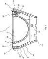
- Fig. 1 shows an example of a Schuhaubenvorsch invention 1 or a heating hood 1.
- the heating hood 1 has a heat transfer area 2, in which objects for temperature control can be placed or arranged.
- the heat transfer area 2 is bounded at least in sections by a covering layer 24.
- the covering layer 24 is preferably a thin layer element, which preferably consists at least partially of glass fibers and / or of other or alternative materials. Thin here preferably describes a cross-sectional thickness which is less than 10 mm.
- the covering layer 24 preferably has the function of covering the heating device 8. Additionally or alternatively, the cover layer 24 has the function of a contact between the heating hood and an object 4 (see. Fig. 5 ), in particular a hollow glass body.
- the heating device 8 is preferably designed as a tubular mineral heating.
- an electrical resistance element or heating resistor is preferably arranged in a metal tube.
- the metal tube is preferably made of steel, in particular of stainless steel.
- a filling material, in particular silicon dioxide, is preferably arranged in the tube. Both ends of the tube are particularly preferably closed or sealed.
- the tube preferably has a front section 18 (cf. Fig. 4 ), an end portion 20 (see. Fig. 4 ) and one between the front portion 18 and the end portion 20 arranged intermediate portion 16 (see. Fig. 4 ) on.
- the end portion 16 and the front portion 18 preferably have lead connectors connected to a controller (not shown).
- the heating resistor or the heating element preferably extends exclusively in the intermediate portion 16 and thus spaced from the ends of the tube.
- the heating resistor or heating element is exactly, less than or greater than 20 mm, accurate, less than or greater than 40 mm, accurate, less than or greater than 80 mm, accurate, less than or greater than 100 mm, accurate, less or greater than 120 mm, exactly, less than or more than 140 mm, exactly, less than or more than 200 mm from the respective tube end, whereby the front portion 18 and the end portion 20 are formed correspondingly long.
- the front portion 18 and the end portion 20 preferably form connection areas whose average operating temperature is preferably less than the average operating temperature in the intermediate section 16.
- the reference numeral 25 denotes a holding means for holding the heating device 8.
- the holding means 25 preferably has a plurality, in particular exactly, at least or at most 2, exactly, at least or at most 3, exactly, at least or at the most 4, exactly, at least or at the most 5, exactly, at least or at most 6, exactly, at least or at most 7 insulators on.
- the insulators here are preferably at least partially made of a ceramic material.
- the individual insulators of the holding means 25 are designed as ceramic insulators.
- the individual insulators are equally or substantially evenly spaced from each other in the circumferential direction of the holding means 25.
- An insulator may preferably consist of a first insulator portion 33 and a second insulator portion 34.
- the heating device 8 is surrounded by a wall device 26 at least in the circumferential direction.
- the wall device 26 preferably serves for receiving a means for thermal insulation 28 or filling material or an insulating material, in particular glass wool or gas fiber material.
- the insulation material or the means for thermal insulation 28 is in this case preferably arranged between the heating device 8 and the wall device 26.
- the wall device 26 preferably forms a type of receptacle or receptacle, which also serves to collect spilled or overcooking substances and thereby prevents these substances from coming into contact with the housing shell or the frame device 6.
- the wall device 26 and the frame device 6 are aligned with one another and arranged such that a slot 10 is formed in a region between the wall device 26 and the frame device 6.
- the slot 10 in this case connects an air inlet, which is arranged on a first side 12 of the frame device 6, with an air outlet which is arranged on a second side 14 of the frame device 6.
- the air inlet in the region of the bottom of the Edelhaubenvorraum 1, in particular on the underside of the Schuhaubenvoriques 1 is formed.
- the frame device 6 is hereby preferably funnel-shaped and supports at least indirectly and preferably directly the wall device 26 and / or the heating device 8 and / or the holding means 25.
- a chimney effect is sucked through the cold air through the air inlet.
- the sucked air is moved through the slot 10 and conveyed out of the Schuhaubenvorraum 1 via the air outlet.
- the air forms an insulating layer, by means of which a heat transfer of the heat of the heating device 8 to the frame device 6 is at least limited or reduced.
- the air conveyed through the heating hood device 1, in particular through the slot 10 causes heat to be absorbed by the wall device 26 and conveyed out of the heating hood device 1.
- the slot 10 is in this case at least partially overlaid on the upper side by a cover 36.
- the cover 36 preferably has a plurality of holes or openings, in particular more than 5, 10, 15 or more than 20 holes or openings through which the air is led out of the heating device 1.
- the cover 36 is preferably designed removable.
- the cover 36 serves to cover transitions between individual devices, receiving device (s), fixing device (s) and / or connections between components, elements and / or devices.
- the cover layer 24 is preferably arranged, in particular arranged detachably or non-detachably.
- the first insulator portion 33 and the second insulator portion 34 of the individual ceramic insulators, which are in contact with the holding means 25, provide a thermal separation between the holding means 25 and the suspension means 32.
- the thermal separation causes heat transfer from the holding means 25 to the frame means 6 prevents or at least reduces.
- the suspension device 32 preferably couples the holding means 25 to the frame device 6.
- the suspension device 32 preferably has the insulator portions 33 and 34 at one end or in the region of one end.
- the suspension device 32 preferably has at one further end a further insulator device, in particular a slot insulator 31.
- the further isolator device is preferably shown in FIG Application arranged in the slot 10 and forms a thermal separation between the suspension device 32 and the frame device 6.
- the further insulator device or the slot insulator 31 preferably consists at least partially and preferably entirely of polyetheretherketone (PEEK).
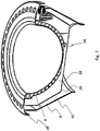
- Fig. 2 shows a perspective view of the in Fig. 1
- the heating device 8 of the heating device 1 is preferably designed as a tubular mineral heating element.
- the design of the heater 8 prevents in particular a fluid inlet and also offers a protection of the heating resistor against overflowing liquids due to their design.
- a significant advantage of the heating device 8 is that it can be used in a meandering or wound or partially or at least partially corrugated, meandering or wound heating element.
- the heating element is preferably spaced by spacer elements 33, 34, in particular by ceramic spacer elements, from the inner wall of the tube.
- the spacer elements 33, 34 may in this case consist, for example, of magnesium oxide and / or silicon dioxide or have magnesium oxide and / or silicon dioxide.
- the tube is preferably at least partially and particularly preferably in terms of volume by a majority or completely filled with a filling material, in particular with silicon dioxide.
- a filling material in particular with silicon dioxide.
- the filling material is preferably created an insulation between the pipe inner wall and the heating element.
- a thermally conductive metallic tube having an inner diameter between 2 mm and 30 mm, in particular between 3 mm and 20 mm, in particular between 3 mm and 15 mm, such as 4 mm, 5 mm, 6 mm, 7 mm, 8 mm, 9 mm, 10 mm, 11 mm, 12 mm, 13 mm or 14 mm, thus preferably protects the heating element, by particularly preferably a completely closed insulation of the heating element is provided.
- the heating element is thus protected from liquid in such a way that no overflowing or overcooking substance can come into contact with the heating element, in particular the heating resistor.
- the heating device 8 used makes it possible to provide a Walkerhaubenvorraum 1 due to the described design, which is operable without a specific circuit protection device in the supply line before the current enters the device.
- a heating element in particular an electrical heating resistor, extends inside the tubular heating device 8, the heating element being spaced apart from the wall of the heating device 8 forming the tubular shape by means of a filling material, in particular silicon dioxide or magnesium oxide, and / or by means of spacing elements.
- a coupling device 30 designed as a suspension device 32 is shown.
- the suspension 32 preferably has in the horizontal part of the slot insulator 31, two discs 43 and two nuts 46.
- the discs 43 are preferably positioned relative to each other such that a frictional connection with a further device, in particular the wall device 26 (see. Fig. 1 ).
- a first insulator portion 33 and a second insulator portion 34 are preferably arranged, wherein the insulator portions 33 and 34 are preferably positioned by means of discs 45 and nuts 46 to each other.
- the isolator portions 33 and 34 are preferably positioned relative to one another such that they fix, in particular clamp, a further device, in particular the holding means 25.
- the structure of the suspension device 32 causes the heat in the region of the heating device 8 is not due to heat conduction or reduced to a surrounding the frame means 6 housing 44 (see. Fig. 5 ) passes over.
- the preferred ceramic insulators 33, 34 cause that the heat does not pass or reduces from the holding means 25 to the receiving device 32.
- the slot insulator 31 causes the heat from the receiving device 32 is not or reduced to the frame device 6 passes.
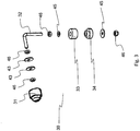
- Fig. 4 shows an exploded view of a heating hood device 1 according to the invention.
- the heater 6 is arranged between preferably three and more preferably evenly distributed in the circumferential direction arranged markings of the holding means 25, a fixation is preferably not required here.
- three insulators in particular of ceramic material or ceramic material having, arranged in three attachment means to the holding means 25 around.
- a suspension device 32 is arranged in each ceramic insulator and arranged uniformly in the circumferential direction of the holding means 25.
- the suspension devices 32 are preferably connected to the isolator via nuts, in particular M2 or M3 or M4 or M5 or M6.
- the heating device 8 is superimposed by a preferably prefabricated and particularly preferably preformed insulation device 28, in particular a glass fiber mat of glass fiber material.
- the insulation device 28 is in turn preferably superimposed by the wall device 26.
- the wall device 26 is preferably made of a material or material mixture, in particular at least partially and preferably in terms of mass majority and particularly preferably entirely of aluminum.
- the wall device 26 is preferably in horizontal areas of the individual suspension devices 32 between flat discs 43 (see. Fig. 3 ) and thereby secured. At the horizontal portion of the hangers 32 are in the range of End of the suspension devices 32 or at the end of the suspension devices 32 each have an insulator, in particular the slot insulator 31, respectively.
- the insulator here preferably consists of polyetheretherketone.
- the isolators arranged in the horizontal portion of the suspension devices 32 are arranged in holes in the frame device 6.
- the cover 36 is preferably attached to the heater assembly 1 after connecting the hangers 32 to the frame means 6.
- the individual in Fig. 4 parts shown individually interchangeable and it is also conceivable that several of the parts shown are interchangeable as a group of components.
- the wall device 26 preferably consists of a metal or metal sheet or of a metal mixture or metal mixture metal sheet.
- the wall device 26 preferably consists at least partially or preferably in the majority of aluminum.
- the frame device 6 is preferably made of a metal or a metal mixture particularly preferably consists of the frame means 6 at least partially or preferably by mass majority of steel, in particular stainless steel.
- the suspension device 32 preferably consists of a metal or of a metal mixture particularly preferably consists of the suspension device 32 at least partially or preferably in terms of mass majority of steel, in particular stainless steel.
- the cover 36 is preferably made of a metal or a metal mixture particularly preferably consists of the cover 36 at least partially or preferably by mass majority of steel, in particular stainless steel.
- Fig. 5 is the arrangement off Fig. 1
- the illustration is supplemented by a housing 44, a holding device 38 and an object 4.
- the holding device 38 preferably serves for defined holding of the object 4, which may preferably be a piston, in particular a glass piston.
- the heating hood according to the invention has a multifunctional design of a housing resistant to chemicals.
- the innovative construction of the heating hood 1 ensures a more efficient heat exchange between the heating device 8 and the glass bulb, so that laboratory work can be carried out faster and more accurately. Furthermore, results in operation of the heating hood from the design of the invention, a "fireplace effect", whereby the housing at any time - even during the application - can be touched from the outside, resulting in a high work safety.
- the heating hood 1 can be easily operated and is very powerful. By means of an electromagnetic stirring component is also a precise and powerful mixing effected.
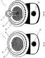
- Fig. 6a 1 shows a heating hood 1 according to the invention.
- the heating hood 1 has a covering layer 24 delimiting the heat transfer area 2 towards the heating device 8.
- the covering layer 24 is preferably formed in sections and preferably completely by a preferably flexible fabric or a preferably flexible mesh.
- the cover layer 24 is preferably superimposed on the upper side by a cover in sections.
- a bulk material 50 which preferably consists of metallic ball or steel balls or aluminum balls or other substantially spherical or cube-shaped bulk material made of metal, is held in the heat transfer region 2, in particular by the cover layer 24, according to this representation.
- a tempering of the heat transfer region 2 thus effects a temperature of the bulk material.
- the reference numeral 52 denotes an optional adjusting device, by means of which preferably the heating power of the heating device 8 can be influenced or regulated.
- Fig. 6b shows against the Fig. 6a additionally an object 4 to be tempered, in particular a test tube or a flask, which is held in contact with the bulk material 50 at least in sections in a region in which a substance to be tempered is held.
- LIST OF REFERENCE NUMBERS 1. heating mantle 30. Coupling device 2. heat transfer area 31. Slot insulator 4th object 32. suspension device 6. Framework 33. first insulator portion 8. Heating device 34. second insulator portion 10. slot 36. cover 12. First page 38. Holding device 14. Second page 40th magnetic element 16th intermediate section 42. Grounding cable 18th front section 43. Slice 20th end section 44. Housing 22. Control device 45th disc 24. Covering layer 46. Mother 25. Holding means 50th bulk material 26. Wall device 52. Adjustment element 28. means for thermal insulation
Landscapes
- Health & Medical Sciences (AREA)
- Clinical Laboratory Science (AREA)
- Chemical & Material Sciences (AREA)
- Chemical Kinetics & Catalysis (AREA)
- Engineering & Computer Science (AREA)
- Mechanical Engineering (AREA)
- General Engineering & Computer Science (AREA)
- Resistance Heating (AREA)
- Tunnel Furnaces (AREA)
- Devices For Use In Laboratory Experiments (AREA)
- Thermotherapy And Cooling Therapy Devices (AREA)
Description
- Die vorliegende Erfindung liegt gemäß Anspruch 1 auf dem Gebiet der Heizhauben. Heizhauben werden in verschiedenen technischen Bereichen, insbesondere der Pharma-, Chemie- und Metallrecyclingindustrie verwendet, um z.B. chemische und biologische Reaktionen oder Destillationsverfahren zu realisieren.
- Bekannte Heizhauben, wie sie z.B. aus der
DE 91 04 442.1 U1 bekannt sind, weisen stets das Problem auf, dass die Wärmeeinbringung in die zu erhitzende Substanz nicht gleichmäßig erfolgt. Ferner führt die Wärmeerzeugung dazu, dass sich jeweils die gesamte Heizhaube sehr stark erhitzt, wodurch für den Untergrund, auf dem die Heizhaube aufsteht, eine größere Beschädigungsgefahr besteht oder wodurch für die Verwender, die mit der Außenseite der Heizhaube in Kontakt kommen können, eine hohe Verletzungsgefahr besteht.
Es ist somit die Aufgabe der vorliegenden Erfindung eine Heizhaube bereitzustellen, die in einem Wärmeübertragungsbereich eine gleichmäßige Erwärmung der zu temperierenden Substanz ermöglicht und dabei die äußeren Gehäuseanteile eine geringere Erwärmung erfahren. - Die zuvor genannte Aufgabe wird erfindungsgemäß durch eine Heizhaube gemäß Anspruch 1 gelöst.
- Die vorliegende Erfindung bezieht sich auf eine Heizhaube, die mindestens einen sphärisch ausgebildeten Wärmeübertragungsbereich, insbesondere zur Aufnahme von zumindest teilweise kugelförmigen Objekten, eine Rahmeneinrichtung, wobei die Position des Wärmeübertragungsbereichs durch die Rahmeneinrichtung zumindest teilweise vorgegeben wird, und eine Heizeinrichtung, umfasst. Die Heizeinrichtung ist zwischen dem Wärmeübertragungsbereich und der Rahmeneinrichtung angeordnet, wobei zwischen der Rahmeneinrichtung und der Heizeinrichtung zumindest abschnittsweise ein Schlitz zum Führen von Luft ausgebildet ist, wobei Luft einerseits der Wandungseinrichtung und der Rahmeneinrichtung in den Schlitz einleitbar ist, wobei die eingeleitete Luft auf einer in Längsrichtung der Rahmeneinrichtung bzw. in zur Umfangsrichtung des Wärmeübertragungsbereichs orthogonaler Richtung beabstandeten zweiten Seite aus dem Schlitz ausleitbar ist. Die Luft wird somit besonders bevorzugt in einem unteren Bereich der Heizhaube in die Heizhaube hineingelassen oder hineingefördert oder eingesaugt. Ferner wird die Luft in einem oberen Bereich der Heizhaube aus der Heizhaube herausgelassen oder herausgefördert oder herausgeleitet. Diese Lösung ist vorteilhaft, da die durch die Heizhaube geleitete Luft zum einen eine isolierende Funktion erfüllt, wodurch weniger der durch die Heizeinrichtung erzeugten Wärme auf die Rahmeneinrichtung übergeht. Ferner fördert die bevorzugt kaminartig bewegte Luft Wärme aus der Heizhaube heraus. Es ist hierbei denkbar, dass eine Gebläseeinrichtung, insbesondere eine elektrisch betriebene Gebläseeinrichtung, zum Fördern der Luft in oder an der Heizhaube vorgesehen ist. Durch den "Kamin-Effekt" ist die Rahmeneinrichtung bzw. das Gehäuse der Heizhaube bevorzugt auch während einer Anwendung z.B. bis 450°C, 500°C, 550°C oder 600°C von außen verletzungsfrei berührbar, wodurch eine hohe Arbeitssicherheit gewährleistet wird.
Weitere bevorzugte Ausführungsformen sind Gegenstand der nachfolgenden Beschreibung oder der Unteransprüche.
Gemäß einer bevorzugten Ausführungsform der vorliegenden Erfindung umschließt die Heizeinrichtung zumindest einmal und bevorzugt mehrfach den Wärmeübertragungsbereich in Umfangsrichtung rohrförmig. Bevorzugt umschließt die Heizeinrichtung den Wärmeübertragungsbereich, insbesondere spiralförmig, genau, mindestens oder höchstens 2 mal, genau, mindestens oder höchstens 3 mal, genau, mindestens oder höchstens 4 mal, genau, mindestens oder höchstens 5 mal, genau, mindestens oder höchstens 6 mal, genau, mindestens oder höchstens 7 mal, genau, mindestens oder höchstens 8 mal, genau, mindestens oder höchstens 9 mal, genau, mindestens oder höchstens 10 mal, genau, mindestens oder höchstens 11 mal, genau, mindestens oder höchstens 12 mal, genau, mindestens oder höchstens 13 mal, genau, mindestens oder höchstens 14 mal, genau, mindestens oder höchstens 15 mal, genau, mindestens oder höchstens 16 mal, genau, mindestens oder höchstens 17 mal, genau, mindestens oder höchstens 18 mal, genau, mindestens oder höchstens 19 mal oder besonders bevorzugt genau, mindestens oder höchstens 20 mal. Diese Ausführungsform ist vorteilhaft, da durch die den Wärmeübertragungsbereich umschließende Heizeinrichtung eine sehr gleichmäßige Temperierung des Wärmeübertragungsbereichs erfolgt bzw. möglich ist. - Im Inneren der rohrförmigen Heizeinrichtung erstreckt sich gemäß einer weiteren bevorzugten Ausführungsform der vorliegenden Erfindung zumindest abschnittsweise und bevorzugt über die gesamte Länge des rohrförmigen Anteils der Heizeinrichtung ein elektrischer Heizwiderstand, wobei der elektrische Heizwiderstand mittels eines Füllmaterials, insbesondere Siliziumdioxid, von der die rohrförmige Gestalt ausbildenden Wandung der Heizeinrichtung beabstandet ist. Bevorzugt ist somit in der zumindest abschnittsweise rohrförmigen Heizeinrichtung zumindest abschnittsweise, insbesondere in dem rohrförmigen Anteil, ein Füllmaterial vorgesehen, durch das der elektrische Heizwiderstand von der Wandung der Heizeinrichtung beabstandet ist. Das Füllmaterial ist hierbei bevorzugt Siliziumdioxid oder weist bevorzugt Siliziumdioxid auf. Besonders bevorzugt besteht das Füllmaterial mehrheitlich, insbesondere mengen- und/oder massenmäßig, aus Siliziumdioxid.
- Gemäß einer weiteren bevorzugten Ausführungsform der vorliegenden Erfindung erstreckt sich der elektrische Heizwiderstand in einem Zwischenabschnitt zwischen einem Frontabschnitt und einem Endabschnitt der rohrförmigen Heizeinrichtung, wobei der Endabschnitt und/oder der Frontabschnitt bevorzugt derart gestaltet sind, dass in einem Betriebszustand, in dem der elektrische Heizwiderstand mit Strom beaufschlagt wird, die durchschnittliche Oberflächentemperatur der rohrförmigen Einrichtung im Zwischenabschnitt größer ist als die durchschnittliche Oberflächentemperatur der rohrförmigen Einrichtung im Frontabschnitt und/oder im Endabschnitt. Diese Ausführungsform ist vorteilhaft, da der Frontabschnitt und der Endabschnitt durch ihre niedrigere Betriebstemperatur einfacher mit einer weiteren Einrichtung, insbesondere einer Steuereinrichtung, verbunden werden können.
- Die Heizeinrichtung ist gemäß einer weiteren bevorzugten Ausführungsform der vorliegenden Erfindung mit einer manuell betätigbaren Steuerungseinrichtung gekoppelt. Diese Ausführungsform ist vorteilhaft, da durch eine Betätigung der Steuerungseinrichtung durch den Nutzer bestimmte Temperaturen und/oder Temperaturverläufe einstallbar bzw. vorgebbar sind.
- Die rohrförmige Heizeinrichtung wird gemäß einer weiteren bevorzugten Ausführungsform der vorliegenden Erfindung von einer den Wärmeübertragungsbereich zumindest abschnittsweise auskleidenden Abdeckschicht überlagert, wobei die Abdeckschicht zumindest teilweise und bevorzugt massemäßig mehrheitlich bevorzugt aus Glasfasern bzw. einer oder mehreren Glasfasermatten bzw. einer Glasfaserschicht/en und/oder einer oder mehreren Aramidfaser/n bzw. Aramidmatte/n besteht. Diese Ausführungsform ist vorteilhaft, da durch die Abdeckschicht eine Schutzschicht bereitgestellt wird, durch welche die Heizeinrichtung vor Beschädigungen geschützt wird. Ferner ist die Abdeckschicht bevorzugt mattenartig ausgebildet, wodurch ein Zusammenstoßen der Abdeckschicht mit einem in den Wärmeübertragungsbereich eingebrachten Temperierungsgegenstand gedämpft wird. Der Temperierungsgegenstand ist bevorzugt ein Glasgefäß, insbesondere ein Glaskolben, zum Erhitzen von darin vorgehaltenen Substanzen.
- Die rohrförmige Heizeinrichtung wird gemäß einer weiteren bevorzugten Ausführungsform der vorliegenden Erfindung durch eine mit der Rahmeneinrichtung gekoppelte Wandungseinrichtung in Umfangsrichtung umschlossen, wobei zwischen der Wandungseinrichtung und der rohrförmigen Heizeinrichtung bevorzugt ein Mittel zum thermischen Dämmen vorgesehen ist. Das Mittel besteht hierbei bevorzugt aus einem Dämmungsmaterial zur Verhinderung oder Reduzierung eines Wärmeübertrags. Es wird so insbesondere eine Wärmeübertragung, z.B. mittels Wärmestrahlung oder Wärmeleitung, reduziert bzw. verhindert.
- Die Wandungseinrichtung und die Rahmeneinrichtung sind gemäß einer weiteren bevorzugten Ausführungsform der vorliegenden Erfindung mittels mehrerer zumindest abschnittsweise thermisch isolierter Kopplungseinrichtungen miteinander verbunden, wobei zwischen der Wandungseinrichtung und der Rahmeneinrichtung zumindest abschnittsweise ein Schlitz zum Führen von Luft ausgebildet ist, wobei Luft einerseits der Wandungseinrichtung und der Rahmeneinrichtung in den Schlitz einleitbar ist, wobei die eingeleitete Luft auf einer in Längsrichtung der Wandungseinrichtung und der Rahmeneinrichtung beabstandeten zweiten Seite aus dem Schlitz ausleitbar ist. Diese Ausführungsform ist vorteilhaft, da die durch die Heizhaube geleitete Luft zum einen eine isolierende Funktion erfüllt, wodurch weniger von der durch die Heizeinrichtung erzeugten Wärme auf die Rahmeneinrichtung übergeht. Ferner fördert die bevorzugt kaminartig bewegte Luft Wärme aus der Heizhaube heraus. Es ist hierbei denkbar, dass eine Gebläseeinrichtung, insbesondere eine elektrisch betriebene Gebläseeinrichtung, zum Fördern der Luft in oder an der Heizhaube vorgesehen ist. Durch den "Kamin-Effekt" ist die Rahmeneinrichtung bzw. das Gehäuse der Heizhaube bevorzugt auch während einer Anwendung z.B. bis 450°C, 500°C oder 550°C von außen verletzungsfrei berührbar, wodurch eine hohe Arbeitssicherheit gewährleistet wird.
- Die zumindest abschnittsweise thermische Isolierung der Kopplungseinrichtungen wird gemäß einer weiteren bevorzugten Ausführungsform der vorliegenden Erfindung derart im Bereich des Schlitzes angeordnet, um eine Wärmeleitungsbarriere zwischen der Rahmeneinrichtung und der Wandungseinrichtung auszubilden. Diese Ausführungsform ist vorteilhaft, da ein Aufheizen der Rahmeneinrichtung in Folge von Wärmeleitung verhindert bzw. reduziert wird.
- Im Wärmeübertragungsbereich, insbesondere auf der Abdeckschicht, ist gemäß einer weiteren bevorzugten Ausführungsform der vorliegenden Erfindung Schüttgut angeordnet, das durch Schüttgutkörner gebildet wird, wobei das Schüttgut infolge einer mechanischen Belastung umpositionierbar ist. Als Schüttgut werden im Rahmen der vorliegenden Erfindung die Gesamtheit aller Festkörperpartikel bzw. -objekte verstanden, die löse in einen Aufnahmebreich hineingeschüttet werden können. Fluide werden im Rahmen der vorliegenden Erfindung explizit nicht als Schüttgut angesehen. Die Umpositionierung des Schüttguts erfolgt bevorzugt durch ein Inkontaktbringen des Schüttguts mit einem zu temperierenden Objekt, insbesondere einem Glaskörper, wie z.B. einem Reagenzglas oder einem Kolben. Diese Ausführungsform ist vorteilhaft, das Schüttgut im Vergleich zu einem Fluid nicht beginnt spontan zu spritzen, sollten unbeabsichtigt Kontaminationen des Schüttguts erfolgen. Heißes Öl hat hingegen z.B. die Eingenschaft, wenn es mit Wasser in Kontakt kommt, das Wasser so schnell aufzuheißen, dass es zu Verpuffungen des Wassers kommen kann. Beispielsweise kann sich dies beim Bruch des zu temperierenden Objekts ergeben, wodurch die im zu temperierenden Objekt vorgehaltene Flüssigkeit in das Öl fließt und dadurch unkontrolliert erhitzt wird. Die Verpuffung der unkontrolliert erhitzten Flüssigkeit kann dabei ein überschwappen des Öls bewirken, woraus eine sehr hohe Verletzungsgefahr für die Bedienperson resultiert. Das Schüttgut ist aufgrund seiner nichtfluidischen Eigenschaften und bevorzugt aufgrund einer höheren Dichte hingegen deutlich weniger schwapp- oder spritzanfällig.
- Die Schüttgutkörner des Schüttguts bestehen gemäß einer weiteren bevorzugten Ausführungsform der vorliegenden Erfindung mehrheitlich aus Metall, wobei bevorzugt alle Schüttgutkörner aus Metall bestehen, wobei die Schüttgutkörner aus dem gleichen Material oder aus unterschiedlichen Materialien bestehen können. Diese Ausführungsform ist vorteilhaft, da die Schüttgutkörner aufgrund ihrer Materialeigenschaften sehr gut Wärme leiten und bevorzugt eine gegenüber Öl größere Dichte aufweisen. Die Verwendung von Metall als Schüttgutkörnermaterial hat ferner die Vorteile, dass es keine Grüche absondert und nicht brennbar ist. Ferner heizt es die zu temperierenden Objekte schneller auf als Öl.
- Die Schüttgutkörner bestehen gemäß einer weiteren bevorzugten Ausführungsform aus metallischem Material, das eine Wärmeleitfähigkeit von mehr als 10 W/(m*K), insbesondere von mehr als 30 W/(m*K) oder von mehr als 50 W/(m*K) oder von mehr als 80 W/(m*K) oder von mehr als 109 W/(m*K) oder von mehr als 119 W/(m*K) oder von mehr als 150 W/(m*K) oder von mehr als 200 W/(m*K) oder von mehr als 230 W/(m*K) oder von mehr als 350 W/(m*K) oder von mehr als 400 W/(m*K) oder von mehr als 420 W/(m*K), aufweist, bevorzugt besteht das metallische Material aus einem der Metalle Eisen, Zink, Messing, Aluminium, Gold, Kupfer und/oder Silber oder weist eines oder mehrere dieser Metalle auf. Diese Ausführungsform ist vorteilhaft, da je nach Einsatzbereich die für die jeweilige Anwendung mit der Heizhaube geeignetste Materialauswahl getroffen werden kann.
- Die Mehrzahl der Schüttgutkörner und bevorzugt alle Schüttgutkörner weisen gemäß einer weiteren bevorzugten Ausführungsform der vorliegenden Erfindung eine zumindest teilweise sphärische Form, insbesondere eine kugelartige Form, auf, wobei der Durchmesser der Mehrzahl der Schüttgutkörner und bevorzugt aller Schüttgutkörner bevorzugt kleiner als 6mm, insbesondere kleiner als 5mm oder kleiner als 4mm oder kleiner als 3mm oder kleiner als 2mm oder kleiner als 1mm, ist. Dies Ausführungsform ist vorteilhaft, durch bei kleineren Durchmessern die verbleiben Bereiche zwischen den einzelnen Schüttgutkörnern kleiner werden und dadurch weniger Luft in diesen Bereichen vorhanden sein kann. Da Luft einen relativ geringe Wärmeleitfähigkeit besitzt, wird bevorzugt versucht möglichst wenig Luft im Bereich zwischen dem zu temperierenden Objekt und der Abdeckschicht 24 vorzuhalten. Weiterhin bezieht sich die vorliegenden Erfindung auf ein Verfahren zum Betreiben einer Heizhaube, insbesondere gemäß einer zuvor und im nachfolgenden beschriebenen Heizhaube. Das erfindungsgemäße Verfahren umfasst bevorzugt mindestens die Schritte: Bereitstellen einer Heizhaube, Einbringen von Schüttgut in den Wärmeübertragungsberiech der Heizhaube, Positionieren eines zu temperierenden Objekts gegenüber der Heizhaube, wobei das Objekt und das Schüttgut in Kontakt gebracht werden, Temperieren des Schüttguts durch die Heizhaube und Temperieren des zu temperierenden Objekts mittels des temperierten Schüttguts.
- Ferner kann sich die vorliegende Erfindung auf eine Verwendung von Schüttgut in der benaspruchten Heizhaube beziehen.
Die Verwendung der Wörter "im Wesentlichen" definiert bevorzugt in allen Fällen, in denen diese Wörter im Rahmen der vorliegenden Schutzrechtsschrift verwendet werden eine Abweichung im Bereich von 1%-30%, insbesondere von 1%-20%, insbesondere von 1%-10%, insbesondere von 1%-5%, insbesondere von 1%-2%, von der Festlegung, die ohne die Verwendung dieser Wörter gegeben wäre.
Einzelne oder alle Darstellungen der im Nachfolgenden beschriebenen Figuren sind bevorzugt als Konstruktionszeichnungen anzusehen, d.h. die sich aus der bzw. den Figuren ergebenden Abmessungen, Proportionen, Funktionszusammenhänge und/oder Anordnungen entsprechen bevorzugt genau oder bevorzugt im Wesentlichen denen der erfindungsgemäßen Vorrichtung bzw. des erfindungsgemäßen Produkts.
Weitere Vorteile, Ziele und Eigenschaften vorliegender Erfindung werden anhand nachfolgender Beschreibung anliegender Zeichnungen erläutert, in welchen beispielhaft erfindungsgemäße Heizhauben dargestellt sind. Elemente der erfindungsgemäßen Heizhauben, welche in den Figuren wenigsten im Wesentlichen hinsichtlich ihrer Funktion übereinstimmen, können hierbei mit gleichen Bezugszeichen gekennzeichnet sein, wobei diese Bauteile bzw. Elemente nicht in allen Figuren beziffert oder erläutert sein müssen. Nachfolgend wird die Erfindung rein beispielhaft anhand der beigefügten Figuren beschrieben.
Darin zeigen: - Fig. 1
- eine Querschnittsdarstellung der erfindungsgemäßen Heizhaubenvorrichtung;
- Fig. 2
- eine perspektivische Ansicht einer der erfindungsgemäßen Heizhaubenvorrichtung in einer Schnittdarstellung;
- Fig. 3
- eine Aufhängeeinrichtung, wie sie gemäß der erfindungsgemäßen Heizhaubenvorrichtung bevorzugt verwendet wird;
- Fig. 4
- eine Explosionsdarstellung der erfindungsgemäßen Heizhaubenvorrichtung;
- Fig. 5
- eine Darstellung entsprechend der
Fig. 1 , wobei ebenfalls eine Halteeinrichtung und ein zu erhitzendes Objekt dargestellt sind - Fig. 6a
- eine Darstellung einer erfindungsgemäßen Heizhaube, die mit Schüttgut ausgestattet ist, und
- Fig. 6b
- eine weitere Darstellung einer erfindungsgemäßen Heizhaube, die mit Schüttgut ausgestattet ist, wobei mit dem Schüttgut ein zu temperierendes Objekt in Kontakt steht.
-
Fig. 1 zeigt ein Beispiel einer erfindungsgemäßen Heizhaubenvorrichtung 1 bzw. eine Heizhaube 1. Die Heizhaube 1 weist einen Wärmeübertragungsbereich 2 auf, in dem Objekte zur Temperierung platzierbar bzw. anordenbar sind. Der Wärmeübertragungsbereich 2 wird zumindest abschnittsweise durch eine Abdeckschicht 24 begrenzt. Die Abdeckschicht 24 ist hierbei bevorzugt ein dünnes Schichtelement, das bevorzugt zumindest teilweise aus Glasfasern und/oder aus weiteren oder alternativen Materialen besteht. Dünn beschreibt hierbei bevorzugt eine Querschnittsdicke, die geringer als 10 mm ist. Die Abdeckschicht 24 hat hierbei bevorzugt die Funktion die Heizeinrichtung 8 zu überdecken. Zusätzlich oder alternativ hat die Abdeckschicht 24 die Funktion einen Kontakt zwischen der Heizhaube und einem Objekt 4 (vgl.Fig. 5 ), insbesondere einem hohlen Glaskörper, zu dämpfen. Die Heizeinrichtung 8 ist bevorzugt als rohrförmige Mineralienheizung ausgeführt. Bevorzugt ist hierbei ein elektrisches Widerstandselement bzw. Heizwiderstand in einem Metallrohr angeordnet. Das Metallrohr besteht hierbei bevorzugt aus Stahl, insbesondere aus rostfreiem Edelstahl. Ferner ist in dem Rohr bevorzugt ein Füllmaterial, insbesondere Silizumdioxid, angeordnet. Beide Enden des Rohres sind besonders bevorzugt verschlossen bzw. versiegelt. Das Rohr weist hierbei bevorzugt einen Frontabschnitt 18 (vgl.Fig. 4 ), einen Endabschnitt 20 (vgl.Fig. 4 ) und einen zwischen dem Frontabschnitt 18 und dem Endabschnitt 20 angeordneten Zwischenabschnitt 16 (vgl.Fig. 4 ) auf. Der Endabschnitt 16 und der Frontabschnitt 18 weisen bevorzugt Leitungsverbinder auf, die mit einer Steuerungseinrichtung (nicht gezeigt) verbunden sind. Der Heizwiderstand bzw. das Heizelement erstreckt sich bevorzugt ausschließlich in dem Zwischenabschnitt 16 und somit beabstandet zu den Enden des Rohrs. Bevorzugt ist der Heizwiderstand bzw. das Heizelement genau, weniger oder mehr als 20 mm, genau, weniger oder mehr als 40 mm, genau, weniger oder mehr als 80 mm, genau, weniger oder mehr als 100 mm, genau, weniger oder mehr als 120 mm, genau, weniger oder mehr als 140 mm, genau, weniger oder mehr als 200 mm von dem jeweiligen Rohrende beabstandet, wodurch der Frontabschnitt 18 und der Endabschnitt 20 entsprechend lang ausgebildet sind. Der Frontabschnitt 18 und der Endabschnitt 20 bilden bevorzugt Anschlussbereiche aus, deren durchschnittliche Betriebstemperatur bevorzugt geringer ist als die durchschnittliche Betriebstemperatur im Zwischenabschnitt 16. Lose Anschlussenden des Frontabschnitts 18 und des Endabschnitts 20 werden bevorzugt verpresst und verschlossen bzw. versiegelt. Weiterhin ist an dem rohrförmigen Element, in dem das Füllmaterial und der Widerstand angeordnet sind, bevorzugt eine Erdungsverbindung bzw. ein Erdungskabel 42 angeordnet. Das Bezugszeichen 25 kennzeichnet ein Haltemittel zum Halten der Heizeinrichtung 8. Das Haltemittel 25 weist bevorzugt mehrere, insbesondere genau, mindestens oder höchstens 2, genau, mindestens oder höchstens 3, genau, mindestens oder höchstens 4, genau, mindestens oder höchstens 5, genau, mindestens oder höchstens 6, genau, mindestens oder höchstens 7 Isolatoren auf. Die Isolatoren bestehen hierbei bevorzugt zumindest teilweise aus einem keramischen Material. Bevorzugt sind die einzelnen Isolatoren des Haltemittels 25 als Keramikisolatoren ausgeführt. Bevorzugt sind die einzelnen Isolatoren gleichmäßig oder im Wesentlichen gleichmäßig voneinander in Umfangsrichtung des Haltemittels 25 beabstandet. Ein Isolator kann hierbei bevorzugt aus einem ersten Isolatoranteil 33 und einem zweiten Isolatoranteil 34 bestehen. - Die Heizeinrichtung 8 wird von einer Wandungseinrichtung 26 zumindest in Umfangsrichtung umschlossen. Die Wandungseinrichtung 26 dient dabei bevorzugt zur Aufnahme eines Mittels zum thermischen Dämmen 28 bzw. Füllmaterials bzw. eines Dämmungsmaterials, insbesondere Glaswolle oder Gasfasermaterial. Das Dämmungsmaterial bzw. das Mittel zum thermischen Dämmen 28 ist hierbei bevorzugt zwischen der Heizeinrichtung 8 und der Wandungseinrichtung 26 angeordnet. Die Wandungseinrichtung 26 bildet bevorzugt eine Art Aufnahmewanne bzw. Aufnahmebehälter aus, der auch zum Auffangen von verschütteten oder überkochenden Substanzen dient und dadurch verhindert, dass diese Substanzen in Kontakt mit der Gehäusehülle bzw. der Rahmeneinrichtung 6 gelangen.
- Die Wandungseinrichtung 26 und die Rahmeneinrichtung 6 sind derart zueinander ausgerichtet und angeordnet, dass sich in einem Bereich zwischen der Wandungseinrichtung 26 und der Rahmeneinrichtung 6 ein Schlitz 10 ausbildet. Der Schlitz 10 verbindet dabei einen Lufteinlass, der auf einer ersten Seite 12 der Rahmeneinrichtung 6 angeordnet, ist mit einem Luftauslass, der auf einer zweiten Seite 14 der Rahmeneinrichtung 6 angeordnet ist. Bevorzugt ist der Lufteinlass im Bereich des Bodens der Heizhaubenvorrichtung 1, insbesondere auf der Unterseite der Heizhaubenvorrichtung 1 ausgebildet. Die Rahmeneinrichtung 6 ist hierbei bevorzugt trichterförmig ausgebildet und stützt zumindest indirekt und bevorzugt direkt die Wandungseinrichtung 26 und/oder die Heizeinrichtung 8 und/oder das Haltemittel 25 ab. Durch den Schlitz 10 und die Abwärme entsteht bevorzugt ein Kamineffekt, durch den kalte Luft über den Lufteinlass eingesaugt wird. Die eingesaugte Luft wird durch den Schlitz 10 bewegt und über den Luftauslass aus der Heizhaubenvorrichtung 1 herausgefördert. Die Luft bildet dabei eine Isolationsschicht, durch welche ein Wärmeübergang der Wärme der Heizeinrichtung 8 auf die Rahmeneinrichtung 6 zumindest begrenzt oder reduziert wird. Ferner bewirkt die durch die Heizhaubenvorrichtung 1, insbesondere durch den Schlitz 10, geförderte Luft, dass Wärme von der Wandungseinrichtung 26 aufgenommen und aus der Heizhaubenvorrichtung 1 herausgefördert wird. Der Schlitz 10 ist hierbei auf der Oberseite zumindest teilweise durch eine Abdeckung 36 überlagert. Die Abdeckung 36 weist bevorzugt eine Vielzahl an Löcher bzw. Öffnungen auf, insbesondere mehr als 5, 10, 15 oder mehr als 20 Löcher bzw. Öffnungen, durch welche die Luft aus der Heizhaubenvorrichtung 1 herausgeführt wird. Die Abdeckung 36 ist bevorzugt demontierbar ausgebildet. Bevorzugt dient die Abdeckung 36 zum Abdecken von Übergängen zwischen einzelnen Einrichtungen, Aufnahmeeinrichtung/en, Fixierungseinrichtung/en und/oder Verbindungen zwischen Bauteilen, Elementen und/oder Einrichtungen. An der Abdeckung 36 ist bevorzugt die Abdeckschicht 24 angeordnet, insbesondere lösbar oder unlösbar angeordnet. Der erste Isolatoranteil 33 und der zweite Isolatoranteil 34 der einzelnen keramischen Isolatoren, die mit dem Haltemittel 25 in Kontakt stehen, schaffen eine thermische Trennung zwischen dem Haltemittel 25 und der Aufhängeeinrichtung 32. Durch die thermische Trennung wird ein Wärmeübergang vom Haltemittel 25 auf die Rahmeneinrichtung 6 verhindert bzw. zumindest reduziert. Die Aufhängeeinrichtung 32 koppelt bevorzugt das Haltemittel 25 mit der Rahmeneinrichtung 6. Die Aufhängeeinrichtung 32 weist bevorzugt an einem Ende bzw. im Bereich eines Endes die Isolatoranteile 33 und 34 auf. Ferner weist die Aufhängeeinrichtung 32 bevorzugt an einem weiteren Ende eine weitere Isolatoreinrichtung, insbesondere einen Schlitzisolator 31 auf. Die weitere Isolatoreinrichtung ist bevorzugt im gezeigten Anwendungsfall im Schlitz 10 angeordnet und bildet eine thermische Trennung zwischen der Aufhängeeinrichtung 32 und der Rahmeneinrichtung 6 aus. Bevorzugt besteht die weitere Isolatoreinrichtung bzw. der Schlitzisolator 31 zumindest teilweise und bevorzugt vollständig aus Polyetheretherketon (PEEK).
-
Fig. 2 zeigt eine perspektivische Ansicht der inFig. 1 gezeigten Heizhaubenvorrichtung 1. Die Heizeinrichtung 8 der Heizhabenvorrichtung 1 ist bevorzugt als rohrförmiges Mineralheizelement ausgebildet. Die Bauart der Heizeinrichtung 8 verhindert insbesondere einen Fluideintritt und bietet aufgrund ihrer Bauart ferner einen Schutz des Heizwiderstandes vor überlaufenden Flüssigkeiten. Ein signifikanter Vorteil der Heizeinrichtung 8 ist, dass darin ein gewelltes bzw. mäanderförmiges oder aufgewickeltes bzw. teilweise oder zumindest teilweise gewelltes, mäanderförmiges oder aufgewickeltes Heizelement verwendet werden kann. Das Heizelement wird dabei bevorzugt durch Abstandselemente 33, 34, insbesondere durch keramische Abstandselemente, von der Innenwand des Rohres beabstandet. Die Abstandselemente 33, 34 können hierbei z.B. aus Magnesiumoxid und/oder Siliziumdioxid bestehen oder Magnesiumoxid und/oder Siliziumdioxid aufweisen. Ferner ist das Rohr bevorzugt zumindest teilweise und besonders bevorzugt volumenmäßig mehrheitlich oder vollständig mit einem Füllmaterial, insbesondere mit Siliziumdioxid, befüllt. Durch das Füllmaterial wird bevorzugt eine Isolation zwischen der Rohrinnenwand und dem Heizelement geschaffen. Ein wärmeleitendes metallisches Rohr mit einem Innendurchmesser zwischen 2 mm und 30 mm, insbesondere zwischen 3 mm und 20 mm, insbesondere zwischen 3 mm und 15 mm, wie z.B. 4 mm, 5 mm, 6 mm, 7 mm, 8 mm, 9 mm, 10 mm, 11 mm, 12 mm, 13 mm oder 14 mm, schützt somit bevorzugt das Heizelement, indem besonders bevorzugt eine vollständig geschlossene Isolierung des Heizelements geschaffen ist. Das Heizelement ist somit derart vor Flüssigkeit geschützt, dass keine überlaufende oder überkochende Substanz mit dem Heizelement, insbesondere dem Heizwiderstand, in Kontakt kommen kann. Die verwendete Heizeinrichtung 8 ermöglicht es aufgrund der beschriebenen Bauform eine Heizhaubenvorrichtung 1 bereitzustellen, die ohne eine spezifische Schaltungsschutzeinrichtung in der Versorgungsleitung vor dem Stromeintritt in das Gerät betreibbar ist. Somit erstreckt sich im Inneren der rohrförmigen Heizeinrichtung 8 zumindest abschnittsweise ein Heizelement, insbesondere ein elektrischer Heizwiderstand, wobei das Heizelement mittels eines Füllmaterials, insbesondere Siliziumdioxid oder Magnesiumoxid, und/oder mittels Abstandselementen von der die rohrförmige Gestalt ausbildenden Wandung der Heizeinrichtung 8 beabstandet ist. - In
Fig. 3 ist eine als Aufhängeeinrichtung 32 ausgeführte Kopplungseinrichtung 30 gezeigt. Die Aufhängeeinrichtung 32 weist dabei bevorzugt im horizontalen Teil den Schlitzisolator 31, zwei Scheiben 43 und zwei Muttern 46 auf. Mittels der Muttern 46 sind die Scheiben 43 bevorzugt derart zueinander positionierbar, dass sich ein Kraftschluss mit einer weiteren Einrichtung, insbesondere der Wandungseinrichtung 26 (vgl.Fig. 1 ), ergibt. Im vertikalen Anteil der Aufhängeeinrichtung 32 sind bevorzugt ein erster Isolatoranteil 33 und ein zweiter Isolatoranteil 34 angeordnet, wobei die Isolatoranteile 33 und 34 bevorzugt mittels Scheiben 45 und Muttern 46 zueinander positionierbar sind. Bevorzugt werden die Isolatoranteile 33 und 34 derart zueinander positioniert, dass sie eine weitere Einrichtung, insbesondere das Haltemittel 25, fixieren, insbesondere festklemmen. Der Aufbau der Aufhängeeinrichtung 32 bewirkt, dass die Hitze im Bereich der Heizeinrichtung 8 nicht infolge von Wärmeleitung bzw. reduziert auf ein die Rahmeneinrichtung 6 umgebendes Gehäuse 44 (vgl.Fig. 5 ) übergeht. Zunächst bewirken die bevorzugt keramischen Isolatoren 33, 34, dass die Wärme nicht bzw. reduziert vom Haltemittel 25 auf die Aufnahmeeinrichtung 32 übergeht. Ferner bewirkt der Schlitzisolator 31, dass die Wärme von der Aufnahmeeinrichtung 32 nicht bzw. reduziert auf die Rahmeneinrichtung 6 übergeht. -
Fig. 4 zeigt eine Explosionsdarstellung einer erfindungsgemäßen Heizhaubenvorrichtung 1. Es ist dabei ersichtlich, dass die Heizeinrichtung 6 zwischen bevorzugt drei und besonders bevorzugt gleichmäßig in Umfangsrichtung verteilt angeordneten Markierungen des Haltemittels 25 angeordnet wird, eine Fixierung ist hierbei bevorzugt nicht erforderlich. Bevorzugt sind drei Isolatoren, insbesondere aus keramischen Material oder keramisches Material aufweisend, in drei Anbringungseinrichtungen um das Haltemittel 25 herum angeordnet. Bevorzugt ist jeweils eine Aufhängeeinrichtung 32 in jedem keramischen Isolator angeordnet und gleichmäßig in Umfangsrichtung des Haltemittels 25 angeordnet. Bevorzugt sind die Aufhängeeinrichtungen 32 über Muttern, insbesondere M2 oder M3 oder M4 oder M5 oder M6, mit dem Isolator verbunden. Bevorzugt wird die Heizeinrichtung 8 durch eine bevorzugt vorgefertigte und besonders bevorzugt vorgeformte Dämmungseinrichtung 28, insbesondere eine Glasfasermatte aus Glasfasermaterial, überlagert. Die Dämmungseinrichtung 28 wird ihrerseits bevorzugt von der Wandungseinrichtung 26 überlagert. Die Wandungseinrichtung 26 besteht bevorzugt aus einem Material oder Materialgemisch, insbesondere zumindest teilweise und bevorzugt massemäßig mehrheitlich und besonders bevorzugt vollständig aus Aluminium. Die Wandungseinrichtung 26 ist bevorzugt in horizontalen Bereichen der einzelnen Aufhängeeinrichtungen 32 zwischen flache Scheiben 43 (vgl.Fig. 3 ) geklemmt und dadurch gesichert. An dem horizontalen Anteil der Aufhängeeinrichtungen 32 sind im Bereich eines Endes der Aufhängeeinrichtungen 32 oder am Ende der Aufhängeeinrichtungen 32 jeweils ein Isolator, insbesondere der Schlitzisolator 31, angeordnet. Der Isolator besteht hierbei bevorzugt aus Polyetheretherketon. Die im horizontalen Anteil der Aufhängeeinrichtungen 32 jeweils angeordneten Isolatoren, werden in Löcher in der Rahmeneinrichtung 6 angeordnet. Die Abdeckung 36 wird bevorzugt nach dem Verbinden der Aufhängeeinrichtungen 32 mit der Rahmeneinrichtung 6 an der Heizhaubenvorrichtung 1 angebracht. Bevorzugt sind die einzelnen inFig. 4 gezeigten Teile einzeln austauschbar, wobei auch denkbar ist, dass mehrere der gezeigten Teile als Bauteilgruppe austauschbar sind. - Die Wandungseinrichtung 26 besteht bevorzugt aus einem Metall bzw. Metallblech oder aus einem Metallgemisch bzw. Metallgemischblech besonders bevorzugt besteht die Wandungseinrichtung 26 zumindest teilweise oder bevorzugt massenmäßig mehrheitlich aus Aluminium. Die Rahmeneinrichtung 6 besteht bevorzugt aus einem Metall oder aus einem Metallgemisch besonders bevorzugt besteht die Rahmeneinrichtung 6 zumindest teilweise oder bevorzugt massenmäßig mehrheitlich aus Stahl, insbesondere aus Edelstahl. Die Aufhängeeinrichtung 32 besteht bevorzugt aus einem Metall oder aus einem Metallgemisch besonders bevorzugt besteht die Aufhängeeinrichtung 32 zumindest teilweise oder bevorzugt massenmäßig mehrheitlich aus Stahl, insbesondere aus Edelstahl. Die Abdeckung 36 besteht bevorzugt aus einem Metall oder aus einem Metallgemisch besonders bevorzugt besteht die Abdeckung 36 zumindest teilweise oder bevorzugt massenmäßig mehrheitlich aus Stahl, insbesondere aus Edelstahl.
- In
Fig. 5 ist die Anordnung ausFig. 1 gezeigt, wobei die Darstellung um ein Gehäuse 44, eine Halteeinrichtung 38 und ein Objekt 4 ergänzt ist. Die Halteeinrichtung 38 dient hierbei bevorzugt zum definierten Halten des Objekts 4, das bevorzugt ein Kolben, insbesondere ein Glaskolben, sein kann. - Die erfindungsgemäße Heizhaube weist ein multifunktionales Design eines Chemikalien resistenten Gehäuses auf. Der innovative Aufbau der Heizhaube 1 sorgt für einen effizienteren Wärmeaustausch zwischen der Heizeinrichtung 8 und dem Glaskolben, sodass Laborarbeiten schneller und exakter durchgeführt werden können. Weiterhin resultiert im Betrieb der Heizhaube aus der erfindungsgemäßen Gestaltung ein "Kamin-Effekt", wodurch das Gehäuse jederzeit - auch während der Anwendung - von außen berührt werden kann, wodurch sich eine hohe Arbeitssicherheit ergibt. Weiterhin kann die Heizhaube 1 leicht bedient werden und ist sehr leistungsstark. Mittels einer elektromagnetischen Rührkomponente ist ferner eine genaue und kräftige Durchmischung bewirkbar.
-
Fig. 6a zeigt eine erfindungsgemäße Heizhaube 1. Die Heizhaube 1 weist eine den Wärmeübertragungsbereich 2 hin zur Heizeinrichtung 8 begrenzende Abdeckschicht 24 auf. Die Abdeckschicht 24 wir hierbei bevorzugt abschnittsweise und bevorzugt vollständig durch ein bevorzugt flexibles Gewebe oder ein bevorzugt flexibles Netz ausgebildet. Die Abdeckschicht 24 wird hierbei bevorzugt oberseitig von einer Abdeckung abschnittsweise überlagert. Ein Schüttgut 50, das bevorzugt aus metallischen Kugel bzw. Stahlkugeln oder Aluminiumkugeln oder auch anderen im wesentlichen kugelförmigem oder würfelförmigem Schüttgut aus Metall besteht, wird gemäß dieser Darstellung in dem Wärmeübertragungsbereich 2 gehalten, insbesondere durch die Abdeckschicht 24. Eine Temperierung des Wärmeübertragungsbereichs 2 bewirkt somit eine Temperierung des Schüttguts.
Das Bezugszeichen 52 kennzeichnet eine optionale Einstelleinrichtung, durch welche bevorzugt die Heizleistung der Heizeinrichtung 8 beeinflusst bzw. geregelt werden kann.
Fig. 6b zeigt gegenüber derFig. 6a zusätzlich noch ein zu temperierendes Objekt 4, insbesondere ein Reagenzglas oder ein Kolben, der in einem Bereich in dem eine zu temperierende Substanz vorgehalten wird, zumindest abschnittsweise von dem Schüttgut 50 kontaktierend umgeben wird.Bezugszeichenliste 1. Heizhaube 30. Kopplungseinrichtung 2. Wärmeübertragungsbereich 31. Schlitzisolator 4. Objekt 32. Aufhängeeinrichtung 6. Rahmeneinrichtung 33. erster Isolatoranteil 8. Heizeinrichtung 34. zweiter Isolatoranteil 10. Schlitz 36. Abdeckung 12. Erste Seite 38. Halteeinrichtung 14. Zweite Seite 40. Magnetelement 16. Zwischenabschnitt 42. Erdungskabel 18. Frontabschnitt 43. Scheibe 20. Endabschnitt 44. Gehäuse 22. Steuerungseinrichtung 45. Scheibe 24. Abdeckschicht 46. Mutter 25. Haltemittel 50. Schüttgut 26. Wandungseinrichtung 52. Einstellelement 28. Mittel zum thermischen Dämmen
Claims (14)
- Heizhaube (1) zum Erhitzen von Substanzen, insbesondere für chemische und/oder pharmazeutische Verfahren,
mindestens umfassend
einen sphärisch ausgebildeten Wärmeübertragungsbereich (2), insbesondere zur Aufnahme von zumindest teilweise kugelförmigen Objekten (4),
eine Rahmeneinrichtung (6), wobei die Position des Wärmeübertragungsbereichs (2) durch die Rahmeneinrichtung (6) zumindest teilweise vorgegeben Wird, und
eine Heizeinrichtung (8),
wobei die Heizeinrichtung (8) zwischen dem Wärmeübertragungsbereich (2) und der Rahmeneinrichtung (6) angeordnet ist,
wobei zwischen der Rahmeneinrichtung (6) und der Heizeinrichtung (8) zumindest abschnittsweise ein Schlitz (10) zum Führen von Luft ausgebildet ist, wobei Luft auf einer ersten Seite (12) der Rahmeneinrichtung (6) in den Schlitz (10) einleitbar ist, wobei die eingeleitete Luft auf einer in Längsrichtung der Rahmeneinrichtung (6) beabstandeten anderen Seite (14) aus dem Schlitz (10) aUsleitbar ist. - Heizhaube (1) nach Anspruch 1, dadurch gekennzeichnet, dass die Heizeinrichtung (8) zumindest einmal und bevorzugt mehrfach den Wärmeübertragungsbereich (2) in Umfangsrichtung umschließt.
- Heizhaube (1) nach einem der Ansprüche 1 bis 2,
dadurch gekennzeichnet, dass
sich im Inneren der rohrförmigen Heizeinrichtung (8) zumindest abschnittsweise ein Heizelement, insbesondere ein elektrischer Heizwiderstand, erstreckt,
wobei das elektrische Heizelement mittels eines Füllmaterials, insbesondere Siliziumdioxid oder Magnesiumoxid, und/oder mittels Abstandselementen von der die rohrförmige Gestalt ausbildenden Wandung der Heizeinrichtung (8) beabstandet ist. - Heizhaube (1) nach einem der vorangegangenen Ansprüche,
dadurch gekennzeichnet, dass
sich der elektrische Heizwiderstand in einem Zwischenabschnitt (16) zwischen einem Frontabschnitt (18) und einem Endabschnitt (20) der rohrförmigen Heizeinrichtung (8) erstreckt, wobei der Endabschnitt (20) und/oder der Frontabschnitt (18) derart gestaltet sind, dass in einem Betriebszustand, in dem der elektrische Heizwiderstand (8) mit Strom beaufschlagt wird, die durchschnittliche Oberflächentemperatur der rohrförmigen Heizeinrichtung (8) im Zwischenabschnitt (16) größer ist als die durchschnittliche Oberflächentemperatur der rohrförmigen Einrichtung im Frontabschnitt (18) und/oder im Endabschnitt (20). - Heizhaube (1) nach einem der vorangegangenen Ansprüche,
dadurch gekennzeichnet, dass
die Heizeinrichtung (8) mit einer manuell betätigbaren Steuerungseinrichtung (22) gekoppelt ist. - Heizhaube (1) nach einem der vorangegangenen Ansprüche,
dadurch gekennzeichnet, dass
die rohrförmige Heizeinrichtung (8) von einer den Wärmeübertragungsbereich (2) zumindest abschnittsweise auskleidenden Abdeckschicht (24) überlagert wird, wobei die Abdeckschicht (24) bevorzugt zumindest teilweise aus Glasfasern besteht. - Heizhaube (1) nach einem der vorangegangenen Ansprüche,
dadurch gekennzeichnet, dass
die rohrförmige Heizeinrichtung (8) durch eine mit der Rahmeneinrichtung (6) gekoppelte Wandungseinrichtung (26) in Umfangsrichtung umschlossen wird, wobei zwischen der Wandungseinrichtung (26) und der rohrförmigen Heizeinrichtung (8) bevorzugt ein Mittel zum thermischen Dämmen (28) vorgesehen ist. - Heizhaube (1) nach einem der vorangegangenen Ansprüche,
dadurch gekennzeichnet, dass
die Wandungseinrichtung (26) und die Rahmeneinrichtung (6) mittels mehrerer zumindest abschnittsweise thermisch isolierter Kopplungseinrichtungen (30) miteinander verbunden sind,
wobei zwischen der Wandungseinrichtung (26) und der Rahmeneinrichtung (6) zumindest abschnittsweise ein Schlitz (10) zum Führen von Luft ausgebildet ist, wobei Luft auf einer ersten Seite (12) der Rahmeneinrichtung (6) in den Schlitz (10) einleitbar ist, wobei die eingeleitete Luft auf einer in Längsrichtung der Rahmeneinrichtung (6) beabstandeten zweiten Seite (14) aus dem Schlitz (10) ausleitbar ist. - Heizhaube (1) nach einem der vorangegangenen Ansprüche,
dadurch gekennzeichnet, dass
die zumindest abschnittsweise thermische Isolierung der Kopplungseinrichtungen (30) derart im Bereich des Schlitzes (10) angeordnet ist, um eine Wärmeleitungsbarriere zwischen der Rahmeneinrichtung (6) und der Wandungseinrichtung (26) auszubilden. - Heizhaube (1) nach einem der vorangegangenen Ansprüche,
dadurch gekennzeichnet, dass
Im Wärmeübertragungsbereich (2), Insbesondere auf der Abdeckschicht (24), Schüttgut (50) angeordnet ist, das durch Schüttgutkörner gebildet wird, wobei das Schüttgut (50) infolge einer mechanischen Belastung umpositionierbar ist. - Heizhaube (1) nach Anspruch 10,
dadurch gekennzeichnet, dass
die Schüttgutkörner des Schüttguts (50) mehrheitlich und bevorzugt alle Schüttgutkörner aus Metall bestehen, wobei die Schüttgutkörner aus dem gleichen Material oder aus unterschiedlichen Materialien bestehen. - Heizhaube (1) nach Anspruch 11,
dadurch gekennzeichnet, dass
die Schüttgutkörner aus metallischem Material bestehen, das eine Wärmeleitfähigkeit von mehr als 10 W/(m*K), insbesondere von mehr als 30 W/(m*K) oder von mehr als 50 W/(m*K) oder von mehr als 80 W/(m*K) oder von mehr als 109 W/(m*K) oder von mehr als 119 W/(m*K) oder von mehr als 150 W/(m*K) oder von mehr als 200 W/(m*K) oder von mehr als 230 W/(m*K) oder von mehr als 350 W/(m*K) oder von mehr als 400 W/(m*K) oder von mehr als 420 W/(m*K), aufweist, bevorzugt besteht das metallische Material aus einem der Metalle Eisen, Zink, Messing, Aluminium, Gold, Kupfer und/oder Silber oder weist eines oder mehrere dieser Metalle auf. - Heizhaube (1) nach Anspruch 10 oder 11,
dadurch gekennzeichnet, dass
die Mehrzahl der Schüttgutkörner und bevorzugt alle Schüttgutkörner eine zumindest teilweise sphärische Form, insbesondere eine kugelartige Form, aufweisen, wobei der Durchmesser der Mehrzahl der Schüttgutkörner und bevorzugt aller Schüttgutkörner bevorzugt kleiner als 6mm, Insbesondere kleiner als 5mm oder kleiner als 4mm oder kleiner als 3mm oder kleiner als 2mm oder kleiner als 1mm, ist. - Verfahren zum Betreiben einer Heizhaube (1) gemäß einem der vorangegangenen Ansprüche,
mindestens umfassend die Schritte:Bereitstellen einer Heizhaube (1),Einbringen von Schüttgut (50) In den Wärmeübertragungsbereich (2) der Heizhaube (1),Positionieren eines zu temperierenden Objekts (4) gegenüber der Heizhaube (1), wobei das Objekt und das Schüttgut (50) in Kontakt gebracht werden,Temperieren des Schüttguts (50) durch die Heizhaube (1) und Temperieren des zu temperierenden Objekts (4) mittels des temperierten Schüttguts (50).
Applications Claiming Priority (2)
| Application Number | Priority Date | Filing Date | Title |
|---|---|---|---|
| DE202014007322.8U DE202014007322U1 (de) | 2014-09-08 | 2014-09-08 | Heizhaubenvorrichtung mit neuartiger Anordnung der Heizeinrichtung |
| PCT/EP2015/070446 WO2016038005A1 (de) | 2014-09-08 | 2015-09-08 | Heizhaubenvorrichtung mit neuartiger anordnung der heizeinrichtung |
Publications (2)
| Publication Number | Publication Date |
|---|---|
| EP3191781A1 EP3191781A1 (de) | 2017-07-19 |
| EP3191781B1 true EP3191781B1 (de) | 2018-09-05 |
Family
ID=54151251
Family Applications (1)
| Application Number | Title | Priority Date | Filing Date |
|---|---|---|---|
| EP15767106.6A Not-in-force EP3191781B1 (de) | 2014-09-08 | 2015-09-08 | Heizhaubenvorrichtung mit neuartiger anordnung der heizeinrichtung und verfahren zum betreiben einer heizhaubenvorrichtung |
Country Status (5)
| Country | Link |
|---|---|
| US (1) | US20170259269A1 (de) |
| EP (1) | EP3191781B1 (de) |
| CN (1) | CN107073349A (de) |
| DE (1) | DE202014007322U1 (de) |
| WO (1) | WO2016038005A1 (de) |
Families Citing this family (4)
| Publication number | Priority date | Publication date | Assignee | Title |
|---|---|---|---|---|
| CN106807469A (zh) * | 2017-03-01 | 2017-06-09 | 四川佳怡德环境科技有限公司 | 防止搅拌器中污水水样翻倒的固定装置 |
| CN108160129A (zh) * | 2017-12-27 | 2018-06-15 | 余婷 | 加热容器 |
| CN114205940B (zh) * | 2021-12-14 | 2024-01-09 | 北京环境特性研究所 | 一种球体辐射源的加热源 |
| CN114311439B (zh) * | 2021-12-31 | 2024-04-05 | 北京星航机电装备有限公司 | 一种用于包装箱箱体成型的恒温加热罩和成型装置 |
Family Cites Families (28)
| Publication number | Priority date | Publication date | Assignee | Title |
|---|---|---|---|---|
| GB630173A (en) * | 1947-06-24 | 1949-10-06 | Heinz Herbert Goldstaub | Improvements in and relating to electrical heating devices |
| CA955635A (en) * | 1969-03-10 | 1974-10-01 | Donald F. Othmer | System for electrically heating a fluid being transported in a pipe |
| US3764780A (en) * | 1971-06-16 | 1973-10-09 | C Ellis | Blood culture apparatus |
| US4164174A (en) * | 1975-09-30 | 1979-08-14 | Wallsten Hans Ivar | Method of preparing foodstuffs by means of boiling or steaming and means for performing the method |
| IL53370A0 (en) * | 1977-11-14 | 1978-01-31 | Uni Seal Decomposition Vessels | Liquid and vapour-tight vessel for performing decomposition reactions |
| US4211251A (en) * | 1978-04-24 | 1980-07-08 | Templeton Coal Co., Inc. | Automatic purging system |
| US4279824A (en) * | 1979-11-01 | 1981-07-21 | Mckinney Laurence O | Method and apparatus for processing herbaceous plant materials including the plant cannabis |
| GB8404549D0 (en) * | 1984-02-21 | 1984-03-28 | Electrothermal Eng Ltd | Electric heating apparatus |
| DE3813042C1 (en) * | 1988-04-19 | 1989-07-06 | Heraeus-Wittmann Gmbh, 6450 Hanau, De | Electrical heating mantle (jacket) |
| US5248486A (en) * | 1989-04-17 | 1993-09-28 | Akira Matsuoka | Device, agent and process for medical waste sterilization |
| US5044428A (en) * | 1989-05-30 | 1991-09-03 | Spectra-Physics, Inc. | Air powered heater/mixer |
| CN2061084U (zh) * | 1989-11-14 | 1990-08-29 | 李秉玉 | 连续调温电热套 |
| EP0466109B1 (de) * | 1990-07-10 | 1994-11-02 | Sumitomo Metal Industries, Ltd. | Verfahren zur Herstellung eines Verbundkörpers auf der Basis von Siliziumcarbid |
| DE4111775C2 (de) * | 1991-04-11 | 1993-10-14 | Isopad Gmbh | Vorrichtung zum Beheizen eines Behältnisses |
| DE9104442U1 (de) * | 1991-04-12 | 1991-06-06 | Isopad GmbH, 6900 Heidelberg | Vorrichtung zum Beheizen eines Behältnisses |
| US6684759B1 (en) * | 1999-11-19 | 2004-02-03 | Vladimir Gorokhovsky | Temperature regulator for a substrate in vapor deposition processes |
| JP4370545B2 (ja) * | 2000-01-27 | 2009-11-25 | 時男 桐山 | マントルヒ−タ− |
| CN2519698Y (zh) * | 2001-11-15 | 2002-11-06 | 徐安文 | 微电脑控时恒温电热套 |
| CN2666316Y (zh) * | 2003-12-22 | 2004-12-29 | 梅合宜 | 电饭锅 |
| US20060289466A1 (en) * | 2005-05-03 | 2006-12-28 | Allied Precision Industries, Inc. | Deicing systems |
| ES1060236Y (es) * | 2005-05-10 | 2005-11-16 | Hernandez Enric Bonet | Calefactor electrico para matraces y similares |
| US7494267B2 (en) * | 2005-08-30 | 2009-02-24 | Chemglass, Inc. | Reaction block for supporting flasks of different sizes for chemical synthesis on a hot plate stirrer |
| US7610962B2 (en) * | 2006-04-21 | 2009-11-03 | Shell Oil Company | Sour gas injection for use with in situ heat treatment |
| EP2082669A2 (de) * | 2008-01-25 | 2009-07-29 | Nestec S.A. | Hybridvorrichtung für die Getränkezubereitung |
| JP3155697U (ja) * | 2009-09-16 | 2009-11-26 | 株式会社 スギヤマゲン | 加熱装置 |
| CN103814417A (zh) * | 2011-09-22 | 2014-05-21 | 户田工业株式会社 | 强磁性氮化铁颗粒粉末的制造方法、各向异性磁铁、粘结磁铁和压粉磁铁 |
| CN102853297A (zh) * | 2012-09-05 | 2013-01-02 | 深圳市众明半导体照明有限公司 | 照明装置 |
| CN202876853U (zh) * | 2012-10-30 | 2013-04-17 | 南通市天时化工有限公司 | 新型加热设备 |
-
2014
- 2014-09-08 DE DE202014007322.8U patent/DE202014007322U1/de not_active Expired - Lifetime
-
2015
- 2015-09-08 EP EP15767106.6A patent/EP3191781B1/de not_active Not-in-force
- 2015-09-08 US US15/509,673 patent/US20170259269A1/en not_active Abandoned
- 2015-09-08 WO PCT/EP2015/070446 patent/WO2016038005A1/de not_active Ceased
- 2015-09-08 CN CN201580048189.4A patent/CN107073349A/zh active Pending
Also Published As
| Publication number | Publication date |
|---|---|
| CN107073349A (zh) | 2017-08-18 |
| US20170259269A1 (en) | 2017-09-14 |
| DE202014007322U1 (de) | 2015-12-09 |
| EP3191781A1 (de) | 2017-07-19 |
| WO2016038005A1 (de) | 2016-03-17 |
Similar Documents
| Publication | Publication Date | Title |
|---|---|---|
| DE2339768C3 (de) | Elektrische Kochplatte | |
| EP3191781A1 (de) | Heizhaubenvorrichtung mit neuartiger anordnung der heizeinrichtung | |
| DE102015114886A1 (de) | Heizvorrichtung für Fluide und Verfahren zur Herstellung einer solchen Heizvorrichtung | |
| EP0578971B1 (de) | Elektrisch beheizbare Kalanderwalze | |
| EP2109476B1 (de) | Atemschlauchsystem mit einem heizelement | |
| EP3223586B1 (de) | Kochfeldvorrichtung | |
| EP0866641A2 (de) | Elektrokochplatte | |
| DE3315657A1 (de) | Elektrokochgeraet | |
| DE19526093C5 (de) | Kochmulde mit einem Steuersensor | |
| DE10029244A1 (de) | Elektrische Heizvorrichtung | |
| AT519235B1 (de) | Schmelzofen | |
| DE102022103569B3 (de) | Wasserheizvorrichtung | |
| DE102007006334B4 (de) | Vorrichtung und Verfahren zum induktiven Erwärmen eines Materials | |
| DE102023126066B4 (de) | Elektrische Heizvorrichtung | |
| DE202005021496U1 (de) | Vorrichtung zum Temperieren einer Fluidleitung | |
| DE3004188A1 (de) | Verfahren und vorrichtung zur formgebung eines heizelementes | |
| DE102018109229A1 (de) | Lötwerkzeug mit einer düsenartigen Lötspitze und einem in der Lötspitze verlaufenden Kanal zur Heißgaszuführung | |
| DE102006002372A1 (de) | Vorrichtung zum Befestigen eines Heizdrahtes | |
| DE60320357T2 (de) | Brenner für auf hoher Temperatur zu behandelndes Material | |
| DE19705667C2 (de) | Kochfeld | |
| DE102019127273A1 (de) | Beheizbare Fluidleitung mit interner und externer Heizeinrichtung | |
| EP2127786B1 (de) | Heizkörper für Durchflussmedien und Verfahren zu dessen Herstellung | |
| DE212005000030U1 (de) | Elektrischer Rohrheizkörper | |
| DE3636571C1 (en) | Electric resistance heating element with cold conductor elements | |
| DE19804179A1 (de) | Beheizbares Sandauslaufrohr für Schienenfahrzeuge und Verfahren zu dessen Herstellung |
Legal Events
| Date | Code | Title | Description |
|---|---|---|---|
| PUAI | Public reference made under article 153(3) epc to a published international application that has entered the european phase |
Free format text: ORIGINAL CODE: 0009012 |
|
| 17P | Request for examination filed |
Effective date: 20170406 |
|
| AK | Designated contracting states |
Kind code of ref document: A1 Designated state(s): AL AT BE BG CH CY CZ DE DK EE ES FI FR GB GR HR HU IE IS IT LI LT LU LV MC MK MT NL NO PL PT RO RS SE SI SK SM TR |
|
| AX | Request for extension of the european patent |
Extension state: BA ME |
|
| DAV | Request for validation of the european patent (deleted) | ||
| DAX | Request for extension of the european patent (deleted) | ||
| GRAP | Despatch of communication of intention to grant a patent |
Free format text: ORIGINAL CODE: EPIDOSNIGR1 |
|
| INTG | Intention to grant announced |
Effective date: 20180504 |
|
| GRAS | Grant fee paid |
Free format text: ORIGINAL CODE: EPIDOSNIGR3 |
|
| GRAA | (expected) grant |
Free format text: ORIGINAL CODE: 0009210 |
|
| AK | Designated contracting states |
Kind code of ref document: B1 Designated state(s): AL AT BE BG CH CY CZ DE DK EE ES FI FR GB GR HR HU IE IS IT LI LT LU LV MC MK MT NL NO PL PT RO RS SE SI SK SM TR |
|
| REG | Reference to a national code |
Ref country code: GB Ref legal event code: FG4D Free format text: NOT ENGLISH |
|
| REG | Reference to a national code |
Ref country code: CH Ref legal event code: EP |
|
| REG | Reference to a national code |
Ref country code: AT Ref legal event code: REF Ref document number: 1038314 Country of ref document: AT Kind code of ref document: T Effective date: 20180915 |
|
| REG | Reference to a national code |
Ref country code: IE Ref legal event code: FG4D Free format text: LANGUAGE OF EP DOCUMENT: GERMAN |
|
| REG | Reference to a national code |
Ref country code: DE Ref legal event code: R096 Ref document number: 502015005760 Country of ref document: DE |
|
| REG | Reference to a national code |
Ref country code: CH Ref legal event code: NV Representative=s name: OFFICE ERNEST T. FREYLINGER S.A., CH |
|
| REG | Reference to a national code |
Ref country code: NL Ref legal event code: MP Effective date: 20180905 |
|
| REG | Reference to a national code |
Ref country code: LT Ref legal event code: MG4D |
|
| PG25 | Lapsed in a contracting state [announced via postgrant information from national office to epo] |
Ref country code: FI Free format text: LAPSE BECAUSE OF FAILURE TO SUBMIT A TRANSLATION OF THE DESCRIPTION OR TO PAY THE FEE WITHIN THE PRESCRIBED TIME-LIMIT Effective date: 20180905 Ref country code: LT Free format text: LAPSE BECAUSE OF FAILURE TO SUBMIT A TRANSLATION OF THE DESCRIPTION OR TO PAY THE FEE WITHIN THE PRESCRIBED TIME-LIMIT Effective date: 20180905 Ref country code: RS Free format text: LAPSE BECAUSE OF FAILURE TO SUBMIT A TRANSLATION OF THE DESCRIPTION OR TO PAY THE FEE WITHIN THE PRESCRIBED TIME-LIMIT Effective date: 20180905 Ref country code: SE Free format text: LAPSE BECAUSE OF FAILURE TO SUBMIT A TRANSLATION OF THE DESCRIPTION OR TO PAY THE FEE WITHIN THE PRESCRIBED TIME-LIMIT Effective date: 20180905 Ref country code: NO Free format text: LAPSE BECAUSE OF FAILURE TO SUBMIT A TRANSLATION OF THE DESCRIPTION OR TO PAY THE FEE WITHIN THE PRESCRIBED TIME-LIMIT Effective date: 20181205 Ref country code: GR Free format text: LAPSE BECAUSE OF FAILURE TO SUBMIT A TRANSLATION OF THE DESCRIPTION OR TO PAY THE FEE WITHIN THE PRESCRIBED TIME-LIMIT Effective date: 20181206 Ref country code: BG Free format text: LAPSE BECAUSE OF FAILURE TO SUBMIT A TRANSLATION OF THE DESCRIPTION OR TO PAY THE FEE WITHIN THE PRESCRIBED TIME-LIMIT Effective date: 20181205 |
|
| PG25 | Lapsed in a contracting state [announced via postgrant information from national office to epo] |
Ref country code: LV Free format text: LAPSE BECAUSE OF FAILURE TO SUBMIT A TRANSLATION OF THE DESCRIPTION OR TO PAY THE FEE WITHIN THE PRESCRIBED TIME-LIMIT Effective date: 20180905 Ref country code: HR Free format text: LAPSE BECAUSE OF FAILURE TO SUBMIT A TRANSLATION OF THE DESCRIPTION OR TO PAY THE FEE WITHIN THE PRESCRIBED TIME-LIMIT Effective date: 20180905 Ref country code: AL Free format text: LAPSE BECAUSE OF FAILURE TO SUBMIT A TRANSLATION OF THE DESCRIPTION OR TO PAY THE FEE WITHIN THE PRESCRIBED TIME-LIMIT Effective date: 20180905 |
|
| PG25 | Lapsed in a contracting state [announced via postgrant information from national office to epo] |
Ref country code: IT Free format text: LAPSE BECAUSE OF FAILURE TO SUBMIT A TRANSLATION OF THE DESCRIPTION OR TO PAY THE FEE WITHIN THE PRESCRIBED TIME-LIMIT Effective date: 20180905 Ref country code: ES Free format text: LAPSE BECAUSE OF FAILURE TO SUBMIT A TRANSLATION OF THE DESCRIPTION OR TO PAY THE FEE WITHIN THE PRESCRIBED TIME-LIMIT Effective date: 20180905 Ref country code: NL Free format text: LAPSE BECAUSE OF FAILURE TO SUBMIT A TRANSLATION OF THE DESCRIPTION OR TO PAY THE FEE WITHIN THE PRESCRIBED TIME-LIMIT Effective date: 20180905 Ref country code: RO Free format text: LAPSE BECAUSE OF FAILURE TO SUBMIT A TRANSLATION OF THE DESCRIPTION OR TO PAY THE FEE WITHIN THE PRESCRIBED TIME-LIMIT Effective date: 20180905 Ref country code: CZ Free format text: LAPSE BECAUSE OF FAILURE TO SUBMIT A TRANSLATION OF THE DESCRIPTION OR TO PAY THE FEE WITHIN THE PRESCRIBED TIME-LIMIT Effective date: 20180905 Ref country code: PL Free format text: LAPSE BECAUSE OF FAILURE TO SUBMIT A TRANSLATION OF THE DESCRIPTION OR TO PAY THE FEE WITHIN THE PRESCRIBED TIME-LIMIT Effective date: 20180905 Ref country code: EE Free format text: LAPSE BECAUSE OF FAILURE TO SUBMIT A TRANSLATION OF THE DESCRIPTION OR TO PAY THE FEE WITHIN THE PRESCRIBED TIME-LIMIT Effective date: 20180905 Ref country code: IS Free format text: LAPSE BECAUSE OF FAILURE TO SUBMIT A TRANSLATION OF THE DESCRIPTION OR TO PAY THE FEE WITHIN THE PRESCRIBED TIME-LIMIT Effective date: 20190105 |
|
| PG25 | Lapsed in a contracting state [announced via postgrant information from national office to epo] |
Ref country code: SK Free format text: LAPSE BECAUSE OF FAILURE TO SUBMIT A TRANSLATION OF THE DESCRIPTION OR TO PAY THE FEE WITHIN THE PRESCRIBED TIME-LIMIT Effective date: 20180905 Ref country code: PT Free format text: LAPSE BECAUSE OF FAILURE TO SUBMIT A TRANSLATION OF THE DESCRIPTION OR TO PAY THE FEE WITHIN THE PRESCRIBED TIME-LIMIT Effective date: 20190105 Ref country code: SM Free format text: LAPSE BECAUSE OF FAILURE TO SUBMIT A TRANSLATION OF THE DESCRIPTION OR TO PAY THE FEE WITHIN THE PRESCRIBED TIME-LIMIT Effective date: 20180905 |
|
| REG | Reference to a national code |
Ref country code: DE Ref legal event code: R097 Ref document number: 502015005760 Country of ref document: DE |
|
| REG | Reference to a national code |
Ref country code: BE Ref legal event code: MM Effective date: 20180930 |
|
| REG | Reference to a national code |
Ref country code: IE Ref legal event code: MM4A |
|
| PG25 | Lapsed in a contracting state [announced via postgrant information from national office to epo] |
Ref country code: LU Free format text: LAPSE BECAUSE OF NON-PAYMENT OF DUE FEES Effective date: 20180908 |
|
| PLBE | No opposition filed within time limit |
Free format text: ORIGINAL CODE: 0009261 |
|
| STAA | Information on the status of an ep patent application or granted ep patent |
Free format text: STATUS: NO OPPOSITION FILED WITHIN TIME LIMIT |
|
| PG25 | Lapsed in a contracting state [announced via postgrant information from national office to epo] |
Ref country code: DK Free format text: LAPSE BECAUSE OF FAILURE TO SUBMIT A TRANSLATION OF THE DESCRIPTION OR TO PAY THE FEE WITHIN THE PRESCRIBED TIME-LIMIT Effective date: 20180905 Ref country code: MC Free format text: LAPSE BECAUSE OF FAILURE TO SUBMIT A TRANSLATION OF THE DESCRIPTION OR TO PAY THE FEE WITHIN THE PRESCRIBED TIME-LIMIT Effective date: 20180905 Ref country code: IE Free format text: LAPSE BECAUSE OF NON-PAYMENT OF DUE FEES Effective date: 20180908 |
|
| 26N | No opposition filed |
Effective date: 20190606 |
|
| PG25 | Lapsed in a contracting state [announced via postgrant information from national office to epo] |
Ref country code: SI Free format text: LAPSE BECAUSE OF FAILURE TO SUBMIT A TRANSLATION OF THE DESCRIPTION OR TO PAY THE FEE WITHIN THE PRESCRIBED TIME-LIMIT Effective date: 20180905 Ref country code: BE Free format text: LAPSE BECAUSE OF NON-PAYMENT OF DUE FEES Effective date: 20180930 |
|
| PG25 | Lapsed in a contracting state [announced via postgrant information from national office to epo] |
Ref country code: MT Free format text: LAPSE BECAUSE OF FAILURE TO SUBMIT A TRANSLATION OF THE DESCRIPTION OR TO PAY THE FEE WITHIN THE PRESCRIBED TIME-LIMIT Effective date: 20180905 |
|
| PG25 | Lapsed in a contracting state [announced via postgrant information from national office to epo] |
Ref country code: TR Free format text: LAPSE BECAUSE OF FAILURE TO SUBMIT A TRANSLATION OF THE DESCRIPTION OR TO PAY THE FEE WITHIN THE PRESCRIBED TIME-LIMIT Effective date: 20180905 |
|
| PG25 | Lapsed in a contracting state [announced via postgrant information from national office to epo] |
Ref country code: MK Free format text: LAPSE BECAUSE OF NON-PAYMENT OF DUE FEES Effective date: 20180905 Ref country code: HU Free format text: LAPSE BECAUSE OF FAILURE TO SUBMIT A TRANSLATION OF THE DESCRIPTION OR TO PAY THE FEE WITHIN THE PRESCRIBED TIME-LIMIT; INVALID AB INITIO Effective date: 20150908 Ref country code: CY Free format text: LAPSE BECAUSE OF FAILURE TO SUBMIT A TRANSLATION OF THE DESCRIPTION OR TO PAY THE FEE WITHIN THE PRESCRIBED TIME-LIMIT Effective date: 20180905 |
|
| PGFP | Annual fee paid to national office [announced via postgrant information from national office to epo] |
Ref country code: FR Payment date: 20210929 Year of fee payment: 7 |
|
| REG | Reference to a national code |
Ref country code: AT Ref legal event code: MM01 Ref document number: 1038314 Country of ref document: AT Kind code of ref document: T Effective date: 20200908 |
|
| PGFP | Annual fee paid to national office [announced via postgrant information from national office to epo] |
Ref country code: GB Payment date: 20210929 Year of fee payment: 7 Ref country code: DE Payment date: 20210929 Year of fee payment: 7 |
|
| PG25 | Lapsed in a contracting state [announced via postgrant information from national office to epo] |
Ref country code: AT Free format text: LAPSE BECAUSE OF NON-PAYMENT OF DUE FEES Effective date: 20200908 |
|
| PGFP | Annual fee paid to national office [announced via postgrant information from national office to epo] |
Ref country code: CH Payment date: 20211022 Year of fee payment: 7 |
|
| REG | Reference to a national code |
Ref country code: DE Ref legal event code: R119 Ref document number: 502015005760 Country of ref document: DE |
|
| REG | Reference to a national code |
Ref country code: CH Ref legal event code: PL |
|
| GBPC | Gb: european patent ceased through non-payment of renewal fee |
Effective date: 20220908 |
|
| PG25 | Lapsed in a contracting state [announced via postgrant information from national office to epo] |
Ref country code: LI Free format text: LAPSE BECAUSE OF NON-PAYMENT OF DUE FEES Effective date: 20220930 Ref country code: FR Free format text: LAPSE BECAUSE OF NON-PAYMENT OF DUE FEES Effective date: 20220930 Ref country code: DE Free format text: LAPSE BECAUSE OF NON-PAYMENT OF DUE FEES Effective date: 20230401 Ref country code: CH Free format text: LAPSE BECAUSE OF NON-PAYMENT OF DUE FEES Effective date: 20220930 |
|
| PG25 | Lapsed in a contracting state [announced via postgrant information from national office to epo] |
Ref country code: GB Free format text: LAPSE BECAUSE OF NON-PAYMENT OF DUE FEES Effective date: 20220908 |