EP3190569A1 - Système de contrôle d'accès à des zones réglementées et à des espaces industriels - Google Patents
Système de contrôle d'accès à des zones réglementées et à des espaces industriels Download PDFInfo
- Publication number
- EP3190569A1 EP3190569A1 EP15837822.4A EP15837822A EP3190569A1 EP 3190569 A1 EP3190569 A1 EP 3190569A1 EP 15837822 A EP15837822 A EP 15837822A EP 3190569 A1 EP3190569 A1 EP 3190569A1
- Authority
- EP
- European Patent Office
- Prior art keywords
- sensor
- antenna
- electrostatic field
- disturbance
- area
- Prior art date
- Legal status (The legal status is an assumption and is not a legal conclusion. Google has not performed a legal analysis and makes no representation as to the accuracy of the status listed.)
- Granted
Links
- 230000005686 electrostatic field Effects 0.000 claims abstract description 54
- 230000009471 action Effects 0.000 claims description 27
- 238000012544 monitoring process Methods 0.000 claims description 22
- 238000004891 communication Methods 0.000 claims description 10
- 230000000694 effects Effects 0.000 claims description 7
- 238000013475 authorization Methods 0.000 claims description 3
- 238000001514 detection method Methods 0.000 description 12
- 238000007726 management method Methods 0.000 description 11
- 241001465754 Metazoa Species 0.000 description 9
- 230000033001 locomotion Effects 0.000 description 9
- 239000002184 metal Substances 0.000 description 6
- 230000000903 blocking effect Effects 0.000 description 5
- 238000013459 approach Methods 0.000 description 3
- 239000004020 conductor Substances 0.000 description 3
- 238000010586 diagram Methods 0.000 description 3
- 238000005259 measurement Methods 0.000 description 3
- 239000000523 sample Substances 0.000 description 3
- 238000009825 accumulation Methods 0.000 description 2
- 230000002547 anomalous effect Effects 0.000 description 2
- 230000004888 barrier function Effects 0.000 description 2
- 230000001419 dependent effect Effects 0.000 description 2
- 230000001747 exhibiting effect Effects 0.000 description 2
- 230000006872 improvement Effects 0.000 description 2
- 239000000463 material Substances 0.000 description 2
- 241000283984 Rodentia Species 0.000 description 1
- 238000007792 addition Methods 0.000 description 1
- 230000008859 change Effects 0.000 description 1
- 238000004140 cleaning Methods 0.000 description 1
- 238000013500 data storage Methods 0.000 description 1
- 230000005672 electromagnetic field Effects 0.000 description 1
- 238000001914 filtration Methods 0.000 description 1
- 230000006870 function Effects 0.000 description 1
- 238000000034 method Methods 0.000 description 1
- 230000003449 preventive effect Effects 0.000 description 1
- 230000008569 process Effects 0.000 description 1
- 238000012545 processing Methods 0.000 description 1
- 230000035945 sensitivity Effects 0.000 description 1
- 230000011664 signaling Effects 0.000 description 1
- 230000000087 stabilizing effect Effects 0.000 description 1
- 238000007619 statistical method Methods 0.000 description 1
- 229940125725 tranquilizer Drugs 0.000 description 1
- 239000003204 tranquilizing agent Substances 0.000 description 1
- 230000002936 tranquilizing effect Effects 0.000 description 1
- XLYOFNOQVPJJNP-UHFFFAOYSA-N water Substances O XLYOFNOQVPJJNP-UHFFFAOYSA-N 0.000 description 1
Images


Classifications
-
- G—PHYSICS
- G08—SIGNALLING
- G08B—SIGNALLING OR CALLING SYSTEMS; ORDER TELEGRAPHS; ALARM SYSTEMS
- G08B13/00—Burglar, theft or intruder alarms
- G08B13/22—Electrical actuation
- G08B13/24—Electrical actuation by interference with electromagnetic field distribution
- G08B13/2491—Intrusion detection systems, i.e. where the body of an intruder causes the interference with the electromagnetic field
-
- G—PHYSICS
- G08—SIGNALLING
- G08B—SIGNALLING OR CALLING SYSTEMS; ORDER TELEGRAPHS; ALARM SYSTEMS
- G08B13/00—Burglar, theft or intruder alarms
- G08B13/22—Electrical actuation
- G08B13/24—Electrical actuation by interference with electromagnetic field distribution
- G08B13/2402—Electronic Article Surveillance [EAS], i.e. systems using tags for detecting removal of a tagged item from a secure area, e.g. tags for detecting shoplifting
- G08B13/2405—Electronic Article Surveillance [EAS], i.e. systems using tags for detecting removal of a tagged item from a secure area, e.g. tags for detecting shoplifting characterised by the tag technology used
- G08B13/2414—Electronic Article Surveillance [EAS], i.e. systems using tags for detecting removal of a tagged item from a secure area, e.g. tags for detecting shoplifting characterised by the tag technology used using inductive tags
- G08B13/2417—Electronic Article Surveillance [EAS], i.e. systems using tags for detecting removal of a tagged item from a secure area, e.g. tags for detecting shoplifting characterised by the tag technology used using inductive tags having a radio frequency identification chip
-
- G—PHYSICS
- G08—SIGNALLING
- G08B—SIGNALLING OR CALLING SYSTEMS; ORDER TELEGRAPHS; ALARM SYSTEMS
- G08B13/00—Burglar, theft or intruder alarms
- G08B13/22—Electrical actuation
- G08B13/24—Electrical actuation by interference with electromagnetic field distribution
- G08B13/2402—Electronic Article Surveillance [EAS], i.e. systems using tags for detecting removal of a tagged item from a secure area, e.g. tags for detecting shoplifting
- G08B13/2465—Aspects related to the EAS system, e.g. system components other than tags
- G08B13/2468—Antenna in system and the related signal processing
-
- G—PHYSICS
- G08—SIGNALLING
- G08B—SIGNALLING OR CALLING SYSTEMS; ORDER TELEGRAPHS; ALARM SYSTEMS
- G08B13/00—Burglar, theft or intruder alarms
- G08B13/22—Electrical actuation
- G08B13/26—Electrical actuation by proximity of an intruder causing variation in capacitance or inductance of a circuit
-
- G—PHYSICS
- G08—SIGNALLING
- G08B—SIGNALLING OR CALLING SYSTEMS; ORDER TELEGRAPHS; ALARM SYSTEMS
- G08B13/00—Burglar, theft or intruder alarms
- G08B13/18—Actuation by interference with heat, light, or radiation of shorter wavelength; Actuation by intruding sources of heat, light, or radiation of shorter wavelength
- G08B13/189—Actuation by interference with heat, light, or radiation of shorter wavelength; Actuation by intruding sources of heat, light, or radiation of shorter wavelength using passive radiation detection systems
- G08B13/194—Actuation by interference with heat, light, or radiation of shorter wavelength; Actuation by intruding sources of heat, light, or radiation of shorter wavelength using passive radiation detection systems using image scanning and comparing systems
- G08B13/196—Actuation by interference with heat, light, or radiation of shorter wavelength; Actuation by intruding sources of heat, light, or radiation of shorter wavelength using passive radiation detection systems using image scanning and comparing systems using television cameras
- G08B13/19602—Image analysis to detect motion of the intruder, e.g. by frame subtraction
Definitions
- the present invention relates to an access control system.
- the invention has a practical application in the safety/security sector, and more specifically in safety/security in public or private open spaces, as well as occupational safety and hygiene.
- the main purpose of the present invention is to control access to prohibited areas by way of a virtual fence which, in another embodiment, also allows detecting crossing points in restricted-access areas, such as platforms, maritime docks or land loading docks, or else to detect an unauthorized access to a restricted safety/security area, such as for example the radius of action of a robot in industrial facilities.
- patent document WO2015/044487 describes an electrostatic field sensor and a security system in indoor spaces that is capable of measuring electrostatic fields and their variations along a metal conductor acting as an antenna or sensing probe. This probe is connected to an electronic circuit capable of decoding said changes in the electrostatic field around the metal conductor of the antenna.
- This system allows measuring disturbance by means of a single antenna, and accordingly inferring the presence of a person, distinguishing said person from an animal or thing by measuring the disturbance itself in a single antenna.
- This system is designed as a preventive proximity alarm detector. It does not describe a system for detecting crossing points in restricted areas or a virtual fence in certain restricted areas, for which purpose it would be necessary to modify the system described in patent document WO2015/044487 .
- patent document US8742925 describes a device for detecting and preventing the falling of an object or of a person on a line of a railway station, and more specifically, a platform.
- This device includes a detector having at least one emitter and one receiver, a falling object/person detector connected to the receiver and controlling the signaling of the tracks and physical barriers arranged along the platform and demarcating a door where the detection device is located.
- JP2010157045 A similar system is described in JP2010157045 . Compared to these documents, the present invention considerably simplifies the detection and control of accidents in railway platforms, resulting in a more cost-effective and sustainable system.
- the system object of the invention integrates a sensor capable of measuring electrostatic fields and their variations in order to determine human presence in a surrounding area close to said probe and distinguishing it from any other animal or object.
- the invention is based in the capacity that the sensor object of the invention has for measuring variations in the electrostatic field existing around a conductor acting like an antenna, when said field is affected by the influence of a body, the electrostatic field changes, the sensitivity of the sensor being enough to detect said change caused by a person or another object.
- the human body has its own electrical characteristics dependent on materials, density, volume, temperature and conductivity.
- the differences in potential between the different objects mean that there are electrostatic discharges from one object to another when them come into contact with one another or are very close to one another.
- This effect is utilized by the sensor object of the invention, which continuously measures the fluctuations caused by said field in an electronic circuit connected to it. Through the changes in magnitude of the field, this circuit is capable of distinguishing different types of bodies or objects and discriminating human presence from another material or animal presence.
- the sensor object of the invention indeed shapes the electromagnetic and electrostatic field generated in the antenna and through infinite field lines, a processor connected to same allows determining the volume and density of matter generating the fluctuation in the field in the antenna.
- the invention is applied to safety/security systems in industrial facilities, where the operator will be notified of the risk entailed in getting closer to a given restricted or unauthorized area.
- This for example, in the area of activity of a robot arm allows said arm to be still when an operator is in its radius of action, regardless of whether the actual operator is later held accountable if said operator was not authorized to that end, for which purpose the system also identifies the operator.
- Another object of the present invention relates to an access control system for use in restricted areas that is more precise and easier to implement than the systems described in the prior art, so it is implemented by means of measuring disturbances produced in an electrostatic field due to human presence in the vicinity thereof.
- This access control system will be made up of at least one virtual fence or a crossing point detector in sensitive or restricted areas, such as railway platforms or loading and/or port docks.
- the virtual fence or the crossing point detector comprises at least one electrostatic sensor capable of measuring disturbances generated by people, objects or animals around an antenna which, in turn, emits an electrostatic field and detects disturbances produced in the emitted field.
- This antenna generally an electrode, emits the electrostatic field in a directed manner, i.e., it can emit into a portion of the surrounding space and not in an omnidirectional manner, shielding the unwanted part. This is why the arrangement of this antenna is different in each application because each antenna is autonomous for detecting a disturbance in the electrostatic field generated around same, even though they are connected to a single circuit.
- this system is configured as a crossing point detector for use in restricted areas due to their danger, such as railway platforms, merchandise loading docks or maritime docks, simplifying security tasks in the operation thereof, and it can be readily integrated both in the physical space and in the surveillance environment currently used in said facilities, such that it can even allow greater automation of the processes carried out in said facilities.
- the system is configured as a virtual fence which enables identifying users in a much less expensive and much simpler and more effective manner than in systems known in the prior art.
- An object of the invention relates to an access control system for use in restricted areas comprising different practical embodiments, such as control in industrial spaces, a virtual fence or a crossing point detector.
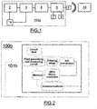
- the electrostatic field sensor (100a) for industrial environments comprises an antenna (1a) consisting of a single measuring electrode.
- the electrostatic field sensor of Figure 1 is a solution based on the sensor described in WO2015/044487 , but improved for implementation in other practical applications.
- the antenna (1a) is directly connected to a field generating circuit (2) and to a field controlling circuit (3) which is in turn connected to a signal processing circuit (4), essentially an analog-digital converter, which is in turn connected to a processor (5) configured for detecting variations in the electrostatic field, establishing a type of three-dimensional map with said variations, the volume and density of the object that generated said variation being able to be determined.
- This processor (5) is in turn connected to a radio frequency communication circuit (6) which emits an encrypted signal to a central control unit (10) which controls the entire facility.
- the processor (5) is connected to a security camera (7) recording the object the processor (5) has detected and defined as an unauthorized intrusion.
- the processor (5) is connected to user identification means (8), preferably through Bluetooth®, in order to allow authorized users to access the site and not generate an alarm signal.
- the electrostatic field sensor comprises an antenna (1 b) consisting of a single electrode that is emitter and receiver (emitting-receiving electrode) at the same time, and it is the antenna (1 b) used in each and every one the embodiments proposed in the present invention, albeit with different physical configurations and connection capabilities that allow improving the functionality thereof. It must be borne in mind that several antennas can coexist in parallel in some embodiments, even through each of them maintains the particularity of being an emitting antenna and a receiving antenna at the same time.
- the controlled electrostatic field sensor also comprises a field generating and measuring circuit, preferably a tuning circuit having a working frequency less than 5 MHz, comprising an RLC circuit and a phase stabilizing circuit.
- a field generating and measuring circuit preferably a tuning circuit having a working frequency less than 5 MHz, comprising an RLC circuit and a phase stabilizing circuit.
- the signal received in the antenna after the measurement, passes through a filtering stage, and said signal then goes to an analog-digital converter, which is in turn connected to a processor configured for detecting variations in the electrostatic field, establishing a type of three-dimensional map with said variations, the volume and density of the object that generated said variation being able to be determined.
- This processor is in turn connected to a radio frequency circuit that emits an encrypted signal to a central control unit or integrated external surveillance system, which controls the entire facility as will be seen in each embodiment.
- the circuit is completed with a data storage memory.
- both embodiments of the electrostatic field sensor (100a, 100b) are not exclusive to one another, i.e., the first embodiment of the sensor (100a) or the second embodiment of the sensor (100b) can be used, as occurs with the antenna (1a, 1b) it actually refers to the same physical element, i.e., an electrode configured as an antenna.
- the electrostatic field sensor (100a, 100b) will be referenced as a sensor (100)
- the antenna (1 a, 1b) in both embodiments will be referenced as an antenna (1).
- Figure 3 shows both the block diagram of the sensor (100) per se described in Figure 1 , and of the central control unit (10) in charge of alarm management, likewise comprising a processor (11) connected to a radio frequency communications module (12) connected to at least one sensor device (100) through its respective radio frequency circuit (6).
- the central control unit (10) is completed with other communications modules, such as Ethernet (13), WIFI (14) or Zigbee (15), further having a capacitive keyboard (16) and a display (17) to make use by operators easier.
- the field generated by the antenna (1) can be directed, that is, depending on the shielding, it is possible to aim the field lines at the desired point of interest, increasing versatility of the invention compared to known alarm systems.
- This system can be used, for example, for controlling the area of movement of an industrial robot, numerical control machines or any other machine for industrial use requiring a restricted-access area for safety/security reasons.
- the object of the central control unit (10) is to simply record the alarms, because the signals are processed by each sensor independently.
- the antenna (1) can have two basic positions:
- Position (a) allows controlling the access of people to the entry of the train, whereas position (b) allows detecting any object that has fallen onto the train tracks. All this is done in a simple manner given that in position (a) the antenna (1) will be simply attached to the ground because it is configured as a metal strip connected to a sensor (100), whereas in position (b) the antenna (1) formed by a metal electrode will be integrated in a channel, anticorrosion pipe, protected against humidity and rodents, or any other type of additional protection.
- the antennas (1) will be shielded such that the electrostatic field generated in option (a) is perpendicular to the ground, whereas the electrostatic field in option (b) is generated substantially parallel to the ground. Therefore, the generated field can be directed depending on the area to be surveilled.
- the train track (402) itself can be configured as an electrode or antenna (1) for detecting people, animals or objects on the track.
- Each of the sensors (3) can control a particular area of the platform (400) because the length of the antenna (1) is preferably equal to or less than ten meters. Therefore, it would be advisable to install a sensor (100) connected to at least one antenna (1) every ten meters for controlling a given area of the platform (400).
- all the sensors (100) are connected to a control device (40) comprising: one or more processors (41); a memory (42); and one or more programs; wherein the program or programs are stored in the memory (42) and configured for being run by means of at least the processor or processors (41), the programs including instructions for: (i) characterizing a disturbance detected by at least one sensor (100); (ii) focusing at least one camera (403) on the area of action of at least one sensor (100) with a detected disturbance; (iii) monitoring the area of action of a sensor (100) with a detected disturbance; (iv) generating a control signal and (v) communicating with the railway management system.
- a control device comprising: one or more processors (41); a memory (42); and one or more programs; wherein the program or programs are stored in the memory (42) and configured for being run by means of at least the processor or processors (41), the programs including instructions for: (i) characterizing a disturbance detected by at least one sensor (100); (i
- Monitoring can be manual (an operator in a control center) or automatic by means of an automatic image recognition system in which the activity of the person who generated the disturbance is monitored and a control signal consistent with same can be generated, said signal being, for example, the automatic reproduction of a generic message of the type "we remind you that it is forbidden to approach the edge of the platform" in the most innocent case up to blocking, should it be required, the passage of trains to the station if, for example, what is detected is a crowd of people or a situation involving the risk of a fall or a fall onto the train tracks themselves.
- a very efficient access control system for controlling access to the railway platform (400) is thereby achieved as it allows characterizing the object, person or people generating the disturbance at a very low cost and without modifying current facilities.
- the described system allows, for example, operations ranging from controlling the platform in a completely individualized manner, detecting the passage or falling of a single person, to the control of crowds, allowing the railway management system to make decisions in a quick and efficient manner with respect to the known prior art.
- the access control system is applicable to maritime loading docks (500) and is particularly useful in container loading docks.
- the antenna (1 b) can have two basic positions:
- Position (a) allows controlling the falling of people or objects into the water, whereas the position (b) allows detecting any object or person that poses an obstacle in the movement of the loading crane (502). All this is done in a simple manner because in both positions (a) and (b), the antenna (1) will simply be attached to the ground because it is configured as a metal strip connected to a sensor (100). The antennas (1) will be shielded such that the electrostatic field is aimed at a predetermined detection area, generally perpendicular to the ground.
- the containers (503) used in the port can each have their own sensor (100) with its own antenna (1). So when the sensor (100) is provided with wireless communication means, this solution allows the container to be controlled not only by means of the system, but it also allows complete pre-loading traceability of said container during its journey in the ship itself and unloading at its destination, provided that there is a connection with a compatible control device (100) in all areas.
- each of the sensors (100) can control a particular area of the maritime dock (500) because the length of the antenna (1) is preferably equal to or less than ten meters. Therefore, it would be advisable to install a sensor (100) connected to at least one antenna (1) every ten meters for controlling a given area of the maritime dock (500).
- all the sensors (100) are connected to a control device (50) comprising: one or more processors (51), a memory (52), and one or more programs; wherein the program or programs are stored in the memory (52) and configured for being run by means of at least the processor or processors (51); wherein the programs include instructions for: (i) characterizing a disturbance detected by at least one sensor (100); (ii) focusing at least one camera (504) on the area of action of at least one sensor (100) with a detected disturbance; (iii) monitoring the area of action of a sensor (100) with a detected disturbance; (iv) generating a control signal and (v) communicating with the port management system.
- a control device comprising: one or more processors (51), a memory (52), and one or more programs; wherein the program or programs are stored in the memory (52) and configured for being run by means of at least the processor or processors (51); wherein the programs include instructions for: (i) characterizing a disturbance detected by at least one sensor (
- At least one sensor (100) will detect a disturbance caused, for example, a person in the area (b) passing under the crane (502).
- the port management system will notify the device (100) of whether or not the crane (502) is in movement, or if said movement is expected soon, or if the load is a risk load. If there is no risk for the person, then the disturbance will be characterized as a "person in restricted area, low-risk", the actual camera (504) of the area of the sensor will focus on and monitor said area.
- Monitoring can be manual (an operator in a control center) or automatic by means of an automatic image recognition system in which the activity of the person who generated the disturbance is monitored and a control signal consistent with same can be generated, said signal being, for example, the automatic reproduction of a generic message of the type "we remind you that it is forbidden to approach the crane" in the most innocent case up to blocking, should it be required, the movement of the crane or the loading of containers if, for example, what is detected is a risk for the people or a situation of accumulation or falling of containers or another anomalous situation.
- a very efficient access control system for controlling access to a maritime dock (500) is thereby achieved as it allows characterizing the object, person or people generating the disturbance at a very low cost and without modifying current facilities.
- the described system allows, for example, operations ranging from controlling the maritime dock (500) in a completely individualized manner, detecting the access of a single person, to the control and traceability of containers, providing the loading management system with an improvement in making decisions in a quick and efficient manner compared to the known prior art, which enables a higher degree of automation in the facility.
- the access control system is applicable to merchandise loading bays (600) and is particularly useful in load automation.
- the antenna (1) can have two basic positions:
- Position (a) allows controlling access to the loading area or region, whereas position (b) allows detecting any object or person falling from the bay (600). All this is done in a simple manner because in both positions (a) and (b), the antenna (1) will simply be attached to the ground because it is configured as a metal strip connected to a sensor (100). The antennas (1) will be shielded such that the electrostatic field is aimed at a predetermined detection area, generally perpendicular to the ground.
- the merchandise (602) can each have its own sensor (100) with its own antenna (1). So when the sensor (100) is provided with wireless communication means, this solution allows the merchandise to be controlled not only by means of the system, but it also allows complete pre-loading traceability of said merchandise during its journey and unloading at its destination, provided that there is a connection with a compatible device (100) in all areas.
- each of the sensors (100) can control a bay (600), is sufficient for controlling a bay because they rarely exceed ten meters in length, which is the maximum distance of each antenna (1) for each sensor (100).
- all the sensors (100) are connected to a control device (60) comprising: one or more processors (61), a memory (62), and one or more programs; wherein the program or programs are stored in the memory (62) and configured for being run by means of at least the processor or processors (61); wherein the programs include instructions for: (i) characterizing a disturbance detected by at least one sensor (100); (ii) focusing at least one camera (603) on the area of action of at least one sensor (100) with a detected disturbance; (iii) monitoring the area of action of a sensor (100) with a detected disturbance; (iv) generating a control signal and (v) communicating with the automatic loading management system.
- a control device comprising: one or more processors (61), a memory (62), and one or more programs; wherein the program or programs are stored in the memory (62) and configured for being run by means of at least the processor or processors (61); wherein the programs include instructions for: (i) characterizing a disturbance detected by at least one sensor
- At least one sensor (100) will detect a disturbance caused, for example, by a person passing through the loading area (a).
- the automatic loading management system will notify the device (100) of if there is in fact an ongoing loading operation taking place, and therefore if there is merchandise (602) in movement, or if said movement is expected soon, or if the load is a risk load. If there is no risk for the person, then the disturbance will be characterized as "person in restricted area, low-risk", the actual camera (603) of the area of the sensor (100) will focus on and monitor said area.
- Monitoring can be manual (an operator in a control center) or automatic by means of an automatic image recognition system in which the activity of the person or object that generated the disturbance is monitored and a control signal consistent with same can be generated, said signal being, for example, the automatic reproduction of a generic message of the type "we remind you that it is forbidden to approach the bay" in the most innocent case up to blocking, should it be required, the movement of the load if, for example, what is detected is a risk for the people or a situation of accumulation or falling of merchandise or another anomalous situation, such as the recognition of the presence of a person in the area (b) which logically implies a fall or that an operator is in the area of passage of the merchandise to the truck, which entails a serious risk for physical integrity.
- the access control system for controlling access to a restricted area is configured as a virtual fence (700) and is particularly useful in the control of security areas with different degrees of access that are typical for sensitive facilities and that are now solved with different recognition systems (biometric systems or systems for personal identification by means of cards) connected to a database and an authentication system.
- recognition systems biometric systems or systems for personal identification by means of cards
- the virtual fence comprises two antennas (1), each of them being connected to its respective sensor (100) arranged longitudinally in a space in which three security areas (700a, 700b, 700c) are defined.
- Each security area comprises a camera (701 a, 701 b, 701 c) and a wireless connection (702a, 702b, 702c) that can be a WIFI- or Bluetooth®-type connection or another equivalent connection for a person skilled in the art.
- a sensor (100) is connected to the two antennas (1). It is generally considered that the maximum length of an antenna (1) connected to a sensor is ten meters, without there being any restriction as to the number of sensors that can be used in parallel connected to one and the same control device (70).
- the control device (70) comprises: one or more processors (71), a memory (72), and one or more programs; wherein the program or programs are stored in the memory (72) and configured for being run by means of at least the processor or processors (71); wherein the programs include instructions for: (i) characterizing a disturbance detected by at least one sensor (100); (ii) focusing at least one camera (701 a, 701b, 701 c) on the area of action of at least one sensor (100) with a detected disturbance; (iii) monitoring the area of action of a sensor (100) with a detected disturbance; (iv) generating a control signal and (v) communicating with an authentication and authorization system.
- a user in the first security area (700a) will be detected by the sensor (100) and their presence will be characterized by the control device (100) which will focus the camera (701a) of said area on the source of the disturbance.
- monitoring involves: (a) biometric recognition of the user by means of the camera; and/or (b) interrogation of a user identification device (for example, a mobile application of the person himself or herself, or a passive wireless signal emitter) through the wireless connection (702a, 702b, 702c).
- a user identification device for example, a mobile application of the person himself or herself, or a passive wireless signal emitter
- FIG. 8 Another particular embodiment shown in Figure 8 illustrates access control system for controlling access to safes (800) in which the antenna (1) can have two basic positions:
- Position (a) allows controlling the access of people to the restricted area or area close to the safe, whereas position (b) allows detecting any contact with same.
- each antenna of each position will be connected to a different sensor (100) for greater detection and control certainty.
- the system will be completed with a camera (801) that can be aimed at both areas (a) or (b) and a wireless communication device (802) that can be a WIFI- or Bluetooth®-type device or another equivalent device for a person skilled in the art.
- all the sensors (100) are connected to a control device (80) comprising: one or more processors (81), a memory (82), and one or more programs; wherein the program or programs are stored in the memory (82) and configured for being run by means of at least the processor or processors (81), the programs including instructions for: (i) characterizing a disturbance detected by at least one sensor (100); (ii) focusing at least one camera (801) on the area of action of at least one sensor (100) with a detected disturbance; (iii) monitoring the area of action of a sensor (100) with a detected disturbance; (iv) generating a control signal and (v) communicating with an authentication system.
- a control device comprising: one or more processors (81), a memory (82), and one or more programs; wherein the program or programs are stored in the memory (82) and configured for being run by means of at least the processor or processors (81), the programs including instructions for: (i) characterizing a disturbance detected by at least one sensor (100); (ii
- a user in the first security area (a) will be detected by the sensor (100) and their presence will be characterized by the control device (100) which will focus the camera (801) of said area on the source of the disturbance.
- monitoring involves: (a) biometric recognition of the user by means of the camera; and/or (b) interrogation of a user identification device (for example, a mobile application of the person himself or herself, or a passive wireless signal emitter) through the wireless means (802).
- a user identification device for example, a mobile application of the person himself or herself, or a passive wireless signal emitter
- This monitoring results in a query with the authentication system. If the query provides a negative result because the person who caused the disturbance is not authorized, the control signal generated by the control device (100) can result in an alarm or even in the automatic blocking of the safe (800).
- There is a two-fold increase in security in this case as there is a redundancy in identification and surveillance, because the person in area (a) will not have the same permission as in area (
- Safes today require, for example, special permits for cleaning them, granting access to the site and safes to people who, in theory, do not have to touch them, there being a minor security breach that must be solved which is done in a very efficient manner given that it allows characterizing the object, person or people generating the disturbance at a very low cost and without modifying current facilities.
- FIG. 9 Another particular embodiment shown in Figure 9 illustrates the access control system for controlling access to valuable objects (900), for example in museums or exhibits, wherein the antenna (1) can have two basic positions:
- Position (a) allows controlling the access of people to the restricted area or area close to same, whereas position (b) allows detecting any contact with the object.
- each antenna of each position will be connected to a different sensor (100) for greater detection and control certainty.
- the system will be completed with a camera (901) that can be aimed at both areas (a) or (b) and a wireless communication device (902) that can be a WIFI- or Bluetooth®-type device or another equivalent device for a person skilled in the art.
- all the sensors (100) are connected to a control device (90) comprising: one or more processors (91), a memory (92), and one or more programs; wherein the program or programs are stored in the memory (92) and configured for being run by means of at least the processor or processors (91), the programs including instructions for: (i) characterizing a disturbance detected by at least one sensor (100); (ii) focusing at least one camera (91) on the area of action of at least one sensor (100) with a detected disturbance; (iii) monitoring the area of action of a sensor (100) with a detected disturbance (iv) generating a control signal and (v) communicating with an exhibit authentication and/or management system.
- a control device comprising: one or more processors (91), a memory (92), and one or more programs; wherein the program or programs are stored in the memory (92) and configured for being run by means of at least the processor or processors (91), the programs including instructions for: (i) characterizing a disturbance detected by at least one sensor (100);
- monitoring simply involves control of the people observing the object, for example, to establish a headcount or statistical analysis of the viewing of the object.
- monitoring involves: (a) biometric recognition of the user by means of the camera; and/or (b) the interrogation of a user identification device (for example, a mobile application of the person himself or herself, or a passive wireless signal emitter). This monitoring results in a query with the authentication system.
- the control signal generated by the control device (90) can result in an alarm or even in the object (900) being locked up.
Landscapes
- Physics & Mathematics (AREA)
- General Physics & Mathematics (AREA)
- Electromagnetism (AREA)
- Engineering & Computer Science (AREA)
- Automation & Control Theory (AREA)
- Computer Security & Cryptography (AREA)
- Signal Processing (AREA)
- Alarm Systems (AREA)
- Geophysics And Detection Of Objects (AREA)
- Burglar Alarm Systems (AREA)
- Emergency Alarm Devices (AREA)
- Radar Systems Or Details Thereof (AREA)
- Train Traffic Observation, Control, And Security (AREA)
Applications Claiming Priority (2)
| Application Number | Priority Date | Filing Date | Title |
|---|---|---|---|
| ES201431283A ES2565548B1 (es) | 2014-09-03 | 2014-09-03 | Sensor de campos electrostáticos y sistema de seguridad en ambientes industriales |
| PCT/ES2015/070643 WO2016034753A1 (fr) | 2014-09-03 | 2015-09-02 | Système de contrôle d'accès à des zones réglementées et à des espaces industriels |
Publications (3)
| Publication Number | Publication Date |
|---|---|
| EP3190569A1 true EP3190569A1 (fr) | 2017-07-12 |
| EP3190569A4 EP3190569A4 (fr) | 2017-10-11 |
| EP3190569B1 EP3190569B1 (fr) | 2021-03-10 |
Family
ID=55439160
Family Applications (1)
| Application Number | Title | Priority Date | Filing Date |
|---|---|---|---|
| EP15837822.4A Active EP3190569B1 (fr) | 2014-09-03 | 2015-09-02 | Système de contrôle d'accès à des zones réglementées et à des espaces industriels |
Country Status (8)
| Country | Link |
|---|---|
| US (1) | US10403110B2 (fr) |
| EP (1) | EP3190569B1 (fr) |
| JP (1) | JP6670828B2 (fr) |
| CN (1) | CN107004333B (fr) |
| CA (1) | CA2984603C (fr) |
| DK (1) | DK3190569T3 (fr) |
| ES (2) | ES2565548B1 (fr) |
| WO (1) | WO2016034753A1 (fr) |
Cited By (5)
| Publication number | Priority date | Publication date | Assignee | Title |
|---|---|---|---|---|
| EP3553477A1 (fr) | 2018-04-13 | 2019-10-16 | Ontech Security, S.L. | Appareil de mesure de perturbation dans un champ magnétique contrôlé |
| IT202000006883A1 (it) * | 2020-04-01 | 2021-10-01 | St Microelectronics Srl | Sistema e metodo di rilevamento di presenza in un ambiente da monitorare |
| IT202000007942A1 (it) * | 2020-04-15 | 2021-10-15 | St Microelectronics Srl | Dispositivo e metodo di rilevamento di presenza, in particolare per sistemi di anti-intrusione |
| EP4213121A1 (fr) | 2022-01-17 | 2023-07-19 | Ontech Security, SL | Méthode et dispositif pour mesurer les perturbations dans un champ électromagnétique contrôlé |
| EP4212890A1 (fr) | 2022-01-17 | 2023-07-19 | Ontech Security, SL | Méthode et dispositif pour mesurer les perturbations dans un champ électromagnétique contrôlé |
Families Citing this family (3)
| Publication number | Priority date | Publication date | Assignee | Title |
|---|---|---|---|---|
| ES2534702B1 (es) * | 2013-09-24 | 2016-02-09 | Ontech Security, Sl | Sensor de campos electrostáticos y sistema de seguridad en espacios interiores |
| ES2809048A1 (es) * | 2019-09-02 | 2021-03-02 | Univ Malaga | Sistema y procedimiento de control de accesos a un recinto |
| ES2812998A1 (es) * | 2019-09-18 | 2021-03-18 | Vlv Disenos Ind S L | Sistema de control de accesos a torres eolicas |
Family Cites Families (20)
| Publication number | Priority date | Publication date | Assignee | Title |
|---|---|---|---|---|
| US3129415A (en) * | 1961-01-03 | 1964-04-14 | Westinghouse Electric Corp | Proximity detector |
| US3794992A (en) * | 1972-02-07 | 1974-02-26 | Gen Dynamics Corp | Radio frequency intrusion detection system |
| GB1404838A (en) * | 1972-08-02 | 1975-09-03 | Matsuda S | Alarm apparatus utilizing high frequency |
| JPS57140488U (fr) * | 1981-02-26 | 1982-09-02 | ||
| JPH06111146A (ja) * | 1992-09-25 | 1994-04-22 | Hitachi Ltd | 侵入監視装置 |
| US7019648B2 (en) * | 2001-10-17 | 2006-03-28 | Auratek Security Inc. | Intruder/escapee detection system |
| JP4301080B2 (ja) | 2004-05-24 | 2009-07-22 | 船井電機株式会社 | 監視システム |
| JP2006023995A (ja) * | 2004-07-08 | 2006-01-26 | Kyowa Exeo Corp | 侵入警戒システムおよびこのシステムに用いられる警報線の結び方法 |
| WO2008120196A2 (fr) | 2007-03-29 | 2008-10-09 | Sandlinks Systems Ltd. | Barrière virtuelle active utilisant des balises radiofréquences mises dans un réseau maillé |
| US7902979B2 (en) | 2008-04-11 | 2011-03-08 | Raytheon Company | Directed energy beam virtual fence |
| JP2010157045A (ja) | 2008-12-26 | 2010-07-15 | Mitsubishi Electric Building Techno Service Co Ltd | 人身事故防止システム |
| EP2454570B1 (fr) | 2009-07-10 | 2019-05-01 | Suren Systems, Ltd. | Système et procédé de capteur de mouvement infrarouge |
| FR2952888B1 (fr) | 2009-11-26 | 2012-01-06 | Alstom Transport Sa | Dispositif de prevention et de detection de la chute d'un objet sur une voie ferroviaire, et procede de detection de la chute d'un objet sur la voie. |
| CN102959699B (zh) * | 2010-08-06 | 2015-12-09 | 松下电器产业株式会社 | 电路基板及其制造方法 |
| US8922371B2 (en) | 2011-06-09 | 2014-12-30 | Tialinx, Inc. | Distributed sensors for intrusion detection |
| DE102011053314A1 (de) * | 2011-09-06 | 2013-03-07 | Huf Hülsbeck & Fürst Gmbh & Co. Kg | Kapazitive Sensoranordnung |
| GB2514103B (en) | 2013-05-12 | 2017-08-02 | Microsense Solutions Ltd | Bidirectional bistatic radar perimeter intrusion detection system |
| CN203444602U (zh) * | 2013-09-13 | 2014-02-19 | 江南大学 | 周界智能安防系统 |
| ES2534702B1 (es) | 2013-09-24 | 2016-02-09 | Ontech Security, Sl | Sensor de campos electrostáticos y sistema de seguridad en espacios interiores |
| CN203746198U (zh) * | 2014-01-13 | 2014-07-30 | 东南大学 | 空间自有电磁波监测安防系统 |
-
2014
- 2014-09-03 ES ES201431283A patent/ES2565548B1/es not_active Expired - Fee Related
-
2015
- 2015-09-02 WO PCT/ES2015/070643 patent/WO2016034753A1/fr active Application Filing
- 2015-09-02 CN CN201580053878.4A patent/CN107004333B/zh active Active
- 2015-09-02 US US15/508,838 patent/US10403110B2/en active Active
- 2015-09-02 DK DK15837822.4T patent/DK3190569T3/da active
- 2015-09-02 CA CA2984603A patent/CA2984603C/fr active Active
- 2015-09-02 EP EP15837822.4A patent/EP3190569B1/fr active Active
- 2015-09-02 JP JP2017512670A patent/JP6670828B2/ja active Active
- 2015-09-02 ES ES15837822T patent/ES2887124T3/es active Active
Cited By (12)
| Publication number | Priority date | Publication date | Assignee | Title |
|---|---|---|---|---|
| EP3553477A1 (fr) | 2018-04-13 | 2019-10-16 | Ontech Security, S.L. | Appareil de mesure de perturbation dans un champ magnétique contrôlé |
| WO2019197677A1 (fr) | 2018-04-13 | 2019-10-17 | Ontech Security, S.L. | Dispositif permettant de mesurer des perturbations dans un champ magnétique contrôlé |
| IT202000006883A1 (it) * | 2020-04-01 | 2021-10-01 | St Microelectronics Srl | Sistema e metodo di rilevamento di presenza in un ambiente da monitorare |
| EP3889927A1 (fr) * | 2020-04-01 | 2021-10-06 | STMicroelectronics S.r.l. | Système et procédé de détection de présence dans un environnement à surveiller |
| US11847897B2 (en) | 2020-04-01 | 2023-12-19 | Stmicroelectronics S.R.L. | System and method for presence detection in an environment to be monitored |
| IT202000007942A1 (it) * | 2020-04-15 | 2021-10-15 | St Microelectronics Srl | Dispositivo e metodo di rilevamento di presenza, in particolare per sistemi di anti-intrusione |
| EP3896665A1 (fr) * | 2020-04-15 | 2021-10-20 | STMicroelectronics S.r.l. | Dispositif et procédé de détection de présence, en particulier pour systèmes anti-intrusion |
| US11462086B2 (en) | 2020-04-15 | 2022-10-04 | Stmicroelectronics S.R.L. | Presence detection device and method |
| US11941961B2 (en) | 2020-04-15 | 2024-03-26 | Stmicroelectronics S.R.L. | Presence detection device and method |
| EP4213121A1 (fr) | 2022-01-17 | 2023-07-19 | Ontech Security, SL | Méthode et dispositif pour mesurer les perturbations dans un champ électromagnétique contrôlé |
| EP4212890A1 (fr) | 2022-01-17 | 2023-07-19 | Ontech Security, SL | Méthode et dispositif pour mesurer les perturbations dans un champ électromagnétique contrôlé |
| WO2023135355A1 (fr) | 2022-01-17 | 2023-07-20 | Ontech Security, Sl | Procédé et dispositif pour mesurer des perturbations dans un champ électromagnétique contrôlé |
Also Published As
| Publication number | Publication date |
|---|---|
| CA2984603A1 (fr) | 2016-03-10 |
| JP2017527041A (ja) | 2017-09-14 |
| ES2565548B1 (es) | 2017-01-25 |
| WO2016034753A1 (fr) | 2016-03-10 |
| JP6670828B2 (ja) | 2020-03-25 |
| EP3190569B1 (fr) | 2021-03-10 |
| US20180174416A1 (en) | 2018-06-21 |
| CN107004333A (zh) | 2017-08-01 |
| DK3190569T3 (da) | 2021-06-14 |
| US10403110B2 (en) | 2019-09-03 |
| EP3190569A4 (fr) | 2017-10-11 |
| CN107004333B (zh) | 2020-04-24 |
| CA2984603C (fr) | 2022-10-25 |
| ES2565548A1 (es) | 2016-04-05 |
| ES2887124T3 (es) | 2021-12-21 |
Similar Documents
| Publication | Publication Date | Title |
|---|---|---|
| EP3190569B1 (fr) | Système de contrôle d'accès à des zones réglementées et à des espaces industriels | |
| EP3280116B1 (fr) | Système de gardiennage virtuel dynamique basé sur l'emplacement pour la sécurité | |
| US10109178B2 (en) | Apparatus for detecting ferromagnetic objects at a protected doorway assembly | |
| US10324214B2 (en) | Electrostatic field sensor and security system in interior and exterior spaces | |
| US9767663B2 (en) | GPS directed intrusion system with data acquisition | |
| US7978069B2 (en) | Reliable security system by triangulation | |
| KR101800130B1 (ko) | 울타리 주변 영역에서 타겟을 검출하는 방법 및 시스템 | |
| EP3669200B1 (fr) | Appareil magnétique pour protéger une zone protégée | |
| CA2771758C (fr) | Procede et systeme de detection embarque d'une matiere nocive | |
| KR20180066688A (ko) | 딥러닝 및 능동준지도학습을 이용한 디지털 사회 보호막 시스템 | |
| CN108367734B (zh) | 载具安全系统及其方法 | |
| EP1107204A2 (fr) | Système de surveillance infrarouge | |
| KR101828244B1 (ko) | 구조물 감시 시스템 및 방법 | |
| CN117456471B (zh) | 一种周界安防方法、系统、终端设备及存储介质 | |
| KR102428514B1 (ko) | 금속탐지장치 및 이를 이용한 방범방재시스템 | |
| Ščurek et al. | Protection of public universities premises via an implementation of radio frequency identification of people | |
| CN111653054A (zh) | 核设施实物保护系统 | |
| CN110020585A (zh) | 用于使用选择性屏蔽的侵入检测的系统和方法 | |
| Crawford | Sector Equipment Material Capabilities-Module 5. | |
| Stapp | Sector Equipment Material Capabilities. |
Legal Events
| Date | Code | Title | Description |
|---|---|---|---|
| STAA | Information on the status of an ep patent application or granted ep patent |
Free format text: STATUS: THE INTERNATIONAL PUBLICATION HAS BEEN MADE |
|
| PUAI | Public reference made under article 153(3) epc to a published international application that has entered the european phase |
Free format text: ORIGINAL CODE: 0009012 |
|
| STAA | Information on the status of an ep patent application or granted ep patent |
Free format text: STATUS: REQUEST FOR EXAMINATION WAS MADE |
|
| 17P | Request for examination filed |
Effective date: 20170403 |
|
| AK | Designated contracting states |
Kind code of ref document: A1 Designated state(s): AL AT BE BG CH CY CZ DE DK EE ES FI FR GB GR HR HU IE IS IT LI LT LU LV MC MK MT NL NO PL PT RO RS SE SI SK SM TR |
|
| AX | Request for extension of the european patent |
Extension state: BA ME |
|
| STAA | Information on the status of an ep patent application or granted ep patent |
Free format text: STATUS: EXAMINATION IS IN PROGRESS |
|
| A4 | Supplementary search report drawn up and despatched |
Effective date: 20170912 |
|
| RIC1 | Information provided on ipc code assigned before grant |
Ipc: G08B 13/26 20060101ALI20170906BHEP Ipc: G08B 13/24 20060101AFI20170906BHEP |
|
| 17Q | First examination report despatched |
Effective date: 20170925 |
|
| DAV | Request for validation of the european patent (deleted) | ||
| DAX | Request for extension of the european patent (deleted) | ||
| GRAP | Despatch of communication of intention to grant a patent |
Free format text: ORIGINAL CODE: EPIDOSNIGR1 |
|
| STAA | Information on the status of an ep patent application or granted ep patent |
Free format text: STATUS: GRANT OF PATENT IS INTENDED |
|
| INTG | Intention to grant announced |
Effective date: 20200827 |
|
| RAP1 | Party data changed (applicant data changed or rights of an application transferred) |
Owner name: ONTECH SECURITY, SL |
|
| GRAS | Grant fee paid |
Free format text: ORIGINAL CODE: EPIDOSNIGR3 |
|
| STAA | Information on the status of an ep patent application or granted ep patent |
Free format text: STATUS: GRANT OF PATENT IS INTENDED |
|
| GRAA | (expected) grant |
Free format text: ORIGINAL CODE: 0009210 |
|
| STAA | Information on the status of an ep patent application or granted ep patent |
Free format text: STATUS: THE PATENT HAS BEEN GRANTED |
|
| AK | Designated contracting states |
Kind code of ref document: B1 Designated state(s): AL AT BE BG CH CY CZ DE DK EE ES FI FR GB GR HR HU IE IS IT LI LT LU LV MC MK MT NL NO PL PT RO RS SE SI SK SM TR |
|
| REG | Reference to a national code |
Ref country code: GB Ref legal event code: FG4D |
|
| REG | Reference to a national code |
Ref country code: CH Ref legal event code: EP Ref country code: AT Ref legal event code: REF Ref document number: 1370693 Country of ref document: AT Kind code of ref document: T Effective date: 20210315 |
|
| REG | Reference to a national code |
Ref country code: DE Ref legal event code: R096 Ref document number: 602015066786 Country of ref document: DE |
|
| REG | Reference to a national code |
Ref country code: IE Ref legal event code: FG4D |
|
| REG | Reference to a national code |
Ref country code: DE Ref legal event code: R081 Ref document number: 602015066786 Country of ref document: DE Owner name: ONTECH SECURITY, SL, LA RINCONADA, ES Free format text: FORMER OWNER: ONTECH SECURITY SL, LA RINCONADA, ES Ref country code: DK Ref legal event code: T3 Effective date: 20210611 |
|
| REG | Reference to a national code |
Ref country code: NL Ref legal event code: FP |
|
| REG | Reference to a national code |
Ref country code: SE Ref legal event code: TRGR |
|
| REG | Reference to a national code |
Ref country code: LT Ref legal event code: MG9D |
|
| PG25 | Lapsed in a contracting state [announced via postgrant information from national office to epo] |
Ref country code: BG Free format text: LAPSE BECAUSE OF FAILURE TO SUBMIT A TRANSLATION OF THE DESCRIPTION OR TO PAY THE FEE WITHIN THE PRESCRIBED TIME-LIMIT Effective date: 20210610 Ref country code: FI Free format text: LAPSE BECAUSE OF FAILURE TO SUBMIT A TRANSLATION OF THE DESCRIPTION OR TO PAY THE FEE WITHIN THE PRESCRIBED TIME-LIMIT Effective date: 20210310 Ref country code: GR Free format text: LAPSE BECAUSE OF FAILURE TO SUBMIT A TRANSLATION OF THE DESCRIPTION OR TO PAY THE FEE WITHIN THE PRESCRIBED TIME-LIMIT Effective date: 20210611 Ref country code: HR Free format text: LAPSE BECAUSE OF FAILURE TO SUBMIT A TRANSLATION OF THE DESCRIPTION OR TO PAY THE FEE WITHIN THE PRESCRIBED TIME-LIMIT Effective date: 20210310 Ref country code: LT Free format text: LAPSE BECAUSE OF FAILURE TO SUBMIT A TRANSLATION OF THE DESCRIPTION OR TO PAY THE FEE WITHIN THE PRESCRIBED TIME-LIMIT Effective date: 20210310 Ref country code: NO Free format text: LAPSE BECAUSE OF FAILURE TO SUBMIT A TRANSLATION OF THE DESCRIPTION OR TO PAY THE FEE WITHIN THE PRESCRIBED TIME-LIMIT Effective date: 20210610 |
|
| REG | Reference to a national code |
Ref country code: AT Ref legal event code: MK05 Ref document number: 1370693 Country of ref document: AT Kind code of ref document: T Effective date: 20210310 |
|
| PG25 | Lapsed in a contracting state [announced via postgrant information from national office to epo] |
Ref country code: RS Free format text: LAPSE BECAUSE OF FAILURE TO SUBMIT A TRANSLATION OF THE DESCRIPTION OR TO PAY THE FEE WITHIN THE PRESCRIBED TIME-LIMIT Effective date: 20210310 Ref country code: LV Free format text: LAPSE BECAUSE OF FAILURE TO SUBMIT A TRANSLATION OF THE DESCRIPTION OR TO PAY THE FEE WITHIN THE PRESCRIBED TIME-LIMIT Effective date: 20210310 |
|
| PG25 | Lapsed in a contracting state [announced via postgrant information from national office to epo] |
Ref country code: CZ Free format text: LAPSE BECAUSE OF FAILURE TO SUBMIT A TRANSLATION OF THE DESCRIPTION OR TO PAY THE FEE WITHIN THE PRESCRIBED TIME-LIMIT Effective date: 20210310 Ref country code: EE Free format text: LAPSE BECAUSE OF FAILURE TO SUBMIT A TRANSLATION OF THE DESCRIPTION OR TO PAY THE FEE WITHIN THE PRESCRIBED TIME-LIMIT Effective date: 20210310 Ref country code: AT Free format text: LAPSE BECAUSE OF FAILURE TO SUBMIT A TRANSLATION OF THE DESCRIPTION OR TO PAY THE FEE WITHIN THE PRESCRIBED TIME-LIMIT Effective date: 20210310 Ref country code: SM Free format text: LAPSE BECAUSE OF FAILURE TO SUBMIT A TRANSLATION OF THE DESCRIPTION OR TO PAY THE FEE WITHIN THE PRESCRIBED TIME-LIMIT Effective date: 20210310 |
|
| PG25 | Lapsed in a contracting state [announced via postgrant information from national office to epo] |
Ref country code: IS Free format text: LAPSE BECAUSE OF FAILURE TO SUBMIT A TRANSLATION OF THE DESCRIPTION OR TO PAY THE FEE WITHIN THE PRESCRIBED TIME-LIMIT Effective date: 20210710 Ref country code: SK Free format text: LAPSE BECAUSE OF FAILURE TO SUBMIT A TRANSLATION OF THE DESCRIPTION OR TO PAY THE FEE WITHIN THE PRESCRIBED TIME-LIMIT Effective date: 20210310 Ref country code: RO Free format text: LAPSE BECAUSE OF FAILURE TO SUBMIT A TRANSLATION OF THE DESCRIPTION OR TO PAY THE FEE WITHIN THE PRESCRIBED TIME-LIMIT Effective date: 20210310 Ref country code: PT Free format text: LAPSE BECAUSE OF FAILURE TO SUBMIT A TRANSLATION OF THE DESCRIPTION OR TO PAY THE FEE WITHIN THE PRESCRIBED TIME-LIMIT Effective date: 20210712 Ref country code: PL Free format text: LAPSE BECAUSE OF FAILURE TO SUBMIT A TRANSLATION OF THE DESCRIPTION OR TO PAY THE FEE WITHIN THE PRESCRIBED TIME-LIMIT Effective date: 20210310 |
|
| REG | Reference to a national code |
Ref country code: DE Ref legal event code: R097 Ref document number: 602015066786 Country of ref document: DE |
|
| REG | Reference to a national code |
Ref country code: ES Ref legal event code: FG2A Ref document number: 2887124 Country of ref document: ES Kind code of ref document: T3 Effective date: 20211221 |
|
| PLBE | No opposition filed within time limit |
Free format text: ORIGINAL CODE: 0009261 |
|
| STAA | Information on the status of an ep patent application or granted ep patent |
Free format text: STATUS: NO OPPOSITION FILED WITHIN TIME LIMIT |
|
| PG25 | Lapsed in a contracting state [announced via postgrant information from national office to epo] |
Ref country code: AL Free format text: LAPSE BECAUSE OF FAILURE TO SUBMIT A TRANSLATION OF THE DESCRIPTION OR TO PAY THE FEE WITHIN THE PRESCRIBED TIME-LIMIT Effective date: 20210310 |
|
| 26N | No opposition filed |
Effective date: 20211213 |
|
| PG25 | Lapsed in a contracting state [announced via postgrant information from national office to epo] |
Ref country code: SI Free format text: LAPSE BECAUSE OF FAILURE TO SUBMIT A TRANSLATION OF THE DESCRIPTION OR TO PAY THE FEE WITHIN THE PRESCRIBED TIME-LIMIT Effective date: 20210310 |
|
| PG25 | Lapsed in a contracting state [announced via postgrant information from national office to epo] |
Ref country code: IS Free format text: LAPSE BECAUSE OF FAILURE TO SUBMIT A TRANSLATION OF THE DESCRIPTION OR TO PAY THE FEE WITHIN THE PRESCRIBED TIME-LIMIT Effective date: 20210710 Ref country code: MC Free format text: LAPSE BECAUSE OF FAILURE TO SUBMIT A TRANSLATION OF THE DESCRIPTION OR TO PAY THE FEE WITHIN THE PRESCRIBED TIME-LIMIT Effective date: 20210310 |
|
| PGFP | Annual fee paid to national office [announced via postgrant information from national office to epo] |
Ref country code: NL Payment date: 20230227 Year of fee payment: 8 |
|
| PGFP | Annual fee paid to national office [announced via postgrant information from national office to epo] |
Ref country code: LU Payment date: 20230227 Year of fee payment: 8 Ref country code: FR Payment date: 20230227 Year of fee payment: 8 Ref country code: ES Payment date: 20230208 Year of fee payment: 8 Ref country code: DK Payment date: 20230221 Year of fee payment: 8 Ref country code: CH Payment date: 20230221 Year of fee payment: 8 |
|
| PG25 | Lapsed in a contracting state [announced via postgrant information from national office to epo] |
Ref country code: HU Free format text: LAPSE BECAUSE OF FAILURE TO SUBMIT A TRANSLATION OF THE DESCRIPTION OR TO PAY THE FEE WITHIN THE PRESCRIBED TIME-LIMIT; INVALID AB INITIO Effective date: 20150902 |
|
| PGFP | Annual fee paid to national office [announced via postgrant information from national office to epo] |
Ref country code: IT Payment date: 20230221 Year of fee payment: 8 Ref country code: BE Payment date: 20230227 Year of fee payment: 8 Ref country code: SE Payment date: 20230221 Year of fee payment: 8 |
|
| PG25 | Lapsed in a contracting state [announced via postgrant information from national office to epo] |
Ref country code: CY Free format text: LAPSE BECAUSE OF FAILURE TO SUBMIT A TRANSLATION OF THE DESCRIPTION OR TO PAY THE FEE WITHIN THE PRESCRIBED TIME-LIMIT Effective date: 20210310 |
|
| PGFP | Annual fee paid to national office [announced via postgrant information from national office to epo] |
Ref country code: IE Payment date: 20240328 Year of fee payment: 9 |
|
| REG | Reference to a national code |
Ref country code: DK Ref legal event code: EBP Effective date: 20230930 |
|
| PG25 | Lapsed in a contracting state [announced via postgrant information from national office to epo] |
Ref country code: MK Free format text: LAPSE BECAUSE OF FAILURE TO SUBMIT A TRANSLATION OF THE DESCRIPTION OR TO PAY THE FEE WITHIN THE PRESCRIBED TIME-LIMIT Effective date: 20210310 |
|
| PGFP | Annual fee paid to national office [announced via postgrant information from national office to epo] |
Ref country code: DE Payment date: 20240328 Year of fee payment: 9 Ref country code: GB Payment date: 20240328 Year of fee payment: 9 |
|
| REG | Reference to a national code |
Ref country code: CH Ref legal event code: PL Ref country code: SE Ref legal event code: EUG |
|
| REG | Reference to a national code |
Ref country code: NL Ref legal event code: MM Effective date: 20231001 |
|
| PG25 | Lapsed in a contracting state [announced via postgrant information from national office to epo] |
Ref country code: LU Free format text: LAPSE BECAUSE OF NON-PAYMENT OF DUE FEES Effective date: 20230902 |