EP3190018A1 - Sicherheitssteuerung für eine druckluftbremse mit gleitschutzsteuerung - Google Patents
Sicherheitssteuerung für eine druckluftbremse mit gleitschutzsteuerung Download PDFInfo
- Publication number
- EP3190018A1 EP3190018A1 EP17150580.3A EP17150580A EP3190018A1 EP 3190018 A1 EP3190018 A1 EP 3190018A1 EP 17150580 A EP17150580 A EP 17150580A EP 3190018 A1 EP3190018 A1 EP 3190018A1
- Authority
- EP
- European Patent Office
- Prior art keywords
- control
- valve
- brake
- brake pressure
- line
- Prior art date
- Legal status (The legal status is an assumption and is not a legal conclusion. Google has not performed a legal analysis and makes no representation as to the accuracy of the status listed.)
- Granted
Links
Images
Classifications
-
- B—PERFORMING OPERATIONS; TRANSPORTING
- B60—VEHICLES IN GENERAL
- B60T—VEHICLE BRAKE CONTROL SYSTEMS OR PARTS THEREOF; BRAKE CONTROL SYSTEMS OR PARTS THEREOF, IN GENERAL; ARRANGEMENT OF BRAKING ELEMENTS ON VEHICLES IN GENERAL; PORTABLE DEVICES FOR PREVENTING UNWANTED MOVEMENT OF VEHICLES; VEHICLE MODIFICATIONS TO FACILITATE COOLING OF BRAKES
- B60T13/00—Transmitting braking action from initiating means to ultimate brake actuator with power assistance or drive; Brake systems incorporating such transmitting means, e.g. air-pressure brake systems
- B60T13/10—Transmitting braking action from initiating means to ultimate brake actuator with power assistance or drive; Brake systems incorporating such transmitting means, e.g. air-pressure brake systems with fluid assistance, drive, or release
- B60T13/66—Electrical control in fluid-pressure brake systems
- B60T13/665—Electrical control in fluid-pressure brake systems the systems being specially adapted for transferring two or more command signals, e.g. railway systems
-
- B—PERFORMING OPERATIONS; TRANSPORTING
- B60—VEHICLES IN GENERAL
- B60T—VEHICLE BRAKE CONTROL SYSTEMS OR PARTS THEREOF; BRAKE CONTROL SYSTEMS OR PARTS THEREOF, IN GENERAL; ARRANGEMENT OF BRAKING ELEMENTS ON VEHICLES IN GENERAL; PORTABLE DEVICES FOR PREVENTING UNWANTED MOVEMENT OF VEHICLES; VEHICLE MODIFICATIONS TO FACILITATE COOLING OF BRAKES
- B60T17/00—Component parts, details, or accessories of power brake systems not covered by groups B60T8/00, B60T13/00 or B60T15/00, or presenting other characteristic features
- B60T17/18—Safety devices; Monitoring
- B60T17/22—Devices for monitoring or checking brake systems; Signal devices
- B60T17/228—Devices for monitoring or checking brake systems; Signal devices for railway vehicles
-
- B—PERFORMING OPERATIONS; TRANSPORTING
- B60—VEHICLES IN GENERAL
- B60T—VEHICLE BRAKE CONTROL SYSTEMS OR PARTS THEREOF; BRAKE CONTROL SYSTEMS OR PARTS THEREOF, IN GENERAL; ARRANGEMENT OF BRAKING ELEMENTS ON VEHICLES IN GENERAL; PORTABLE DEVICES FOR PREVENTING UNWANTED MOVEMENT OF VEHICLES; VEHICLE MODIFICATIONS TO FACILITATE COOLING OF BRAKES
- B60T8/00—Arrangements for adjusting wheel-braking force to meet varying vehicular or ground-surface conditions, e.g. limiting or varying distribution of braking force
- B60T8/17—Using electrical or electronic regulation means to control braking
- B60T8/1701—Braking or traction control means specially adapted for particular types of vehicles
- B60T8/1705—Braking or traction control means specially adapted for particular types of vehicles for rail vehicles
Definitions
- the present invention relates to a safety control for an air brake, which has an anti-skid control, also referred to as anti-lock braking system, in particular for rail vehicles, as well as a method for controlling the air brake with safety control.
- the invention relates to compressed air brakes, which in the brake pressure line, which is acted upon by a control valve with compressed air and connected to a brake cylinder, have a non-slip valve which can close the brake pressure line or separate from the brake cylinder, and on the other hand, connect the brake cylinder with an outlet can, for example over a portion of the brake pressure line to relax the brake pressure from the brake cylinder.
- the anti-skid valve is controlled, for example, by an antiskid control so that brake pressure applied to the brake pressure line into the brake cylinder by the control valve is released from the brake cylinder through the outlet when there are signals in the antiskid control indicating the stalled wheel is locked ,
- the antiskid valve may have a three-way valve or two simple valves, each having only one input and one output.
- the DE 10344540 B4 describes a generic, driven by compressed air brake for rail vehicles, in which is prevented to prevent blocking depending on the wheel speed applied during braking brake cylinder pressure by an exhaust valve, which is arranged in the compressed air line to the brake cylinder.
- the exhaust valve is controlled by an anti-skid control which receives actual wheel speed signals from pulser to lower the brake pressure applied to the brake cylinder when the actual wheel speed is below the calculated wheel speed proportional to the train speed to prevent the wheel from locking up ,
- the brake of DE 10344540 B4 has the disadvantage that in case of failure of the anti-skid control, the drain valve may remain in the open position and prevents braking when the brake cylinder brake pressure should be applied.
- the invention has as its object to provide a circuit with an effective brake control is made possible in a malfunction of the anti-skid control.
- the circuit is to make the brake functional especially in case of malfunction of a non-skid control, which prevents normal blocking of wheels during braking by releasing brake pressure from the brake cylinder.
- the invention achieves the object with the features of the claims, in particular with an electronic safety control for a compressed air brake for rail vehicles, which has a non-slip valve, which is controlled to prevent the blocking of the wheels at applied brake pressure by a non-slip control.
- the anti-skid valve is generally configured and controlled by the anti-skid control to close the brake pressure line so that the brake cylinder is not further pressurized with brake pressure and to open an outlet to release the pressure present in the brake cylinder to lock the wheel stop or prevent and, with the control or brake valve still open, allow further braking by opening the brake pressure line and closing the outlet.
- the safety controller has signal inputs for the control signals generated by an antiskid controller for controlling an antiskid valve.
- the control signals are transmitted according to the invention preferably by a control signal line from the antiskid control to the antiskid valve, wherein the safety control has control signal inputs for the control signals, e.g. a connection for the control signal line.
- the safety controller may include terminals for the control signals to which the anti-skid valve is connected. For example, the safety controller may forward the control signal line control signals to the anti-skid valve or receive the control signals via a branch line.
- the safety controller is characterized by at least one breaker disposed on the control signal line and arranged to interrupt the control signal line to the anti-skid valve when the safety controller receives an unintended control signal generated by the anti-skid control.
- the control of the anti-skid valve is interrupted by the anti-skid control and the anti-skid valve is controlled to a switching state in which the brake pressure line is continuously connected by a control or brake valve to the brake cylinder and an outlet on the brake pressure line is closed ,
- the brake pressure which is left by a control or brake valve in the brake pressure line, act on the brake cylinder without affecting by the anti-skid valve and drive the braking.
- Due to the interruption of the control signal line an unscheduled control signal of the anti-skid control is not passed to the anti-skid valve, so that the brake is functional and brake pressure acts on the brake cylinder.
- control signal line is de-energized in this switching state by the breaker and the anti-skid valve is configured to connect the brake pressure line continuously from the control or brake valve to the brake cylinder and to close an outlet which is connected to the brake pressure line in the de-energized state.
- An unscheduled control signal is generally one that does not prevent blocking of the wheel as intended with applied brake pressure and, in the unlocked state of the wheel, relieves the brake pressure applied by the control or brake valve to the brake pressure line through the antiskid valve to the brake cylinder and closes the outlet.
- An unscheduled control signal is, for example, one that malfunctions the Anti-slip control is generated, for example, opening the outlet and / or closing the brake pressure line for a longer time than is specified in the anti-slip control, in particular a permanent opening of the outlet and / or a permanent closing of the brake pressure line.
- the safety controller may, for example, have an electronic memory in which the maximum times are stored, for which the anti-skid control activates the anti-skid valve to interrupt the brake pressure line and / or to open the outlet.
- the safety controller is also set up to determine the times for which a control signal is generated by the anti-skid control in order to make the anti-skid valve interrupt the brake pressure line and / or open the outlet, and is set up for the control signal certain times with the maximum times stored in its electronic memory.
- An unscheduled control signal is, for example, one generated by the anti-skid control for interrupting the brake pressure line and / or opening the outlet for a longer time than the stored maximum time therefor.
- the safety controller is set up to control the interrupter to interrupt the control signal line when the brake pressure is applied to the brake pressure line by the control valve.
- the safety controller can Have signal input for a measurement signal indicating the brake pressure in the brake pressure line and / or a signal input for a measurement signal indicating the pressure in the brake cylinder (brake cylinder pressure).
- the safety controller has the advantage that it has no signal line from itself to the anti-skid control, which is in addition to the control signal line.
- the safety controller can control the breaker to restore the control signal line, or stop the break so that the anti-skid valve is returned to control by the anti-skid control.
- the safety control is arranged on a non-slip valve, which is arranged in the brake pressure line and in which a pressure sensor at its first connection is arranged to generate a measurement signal for the pressure in the connected portion of the brake pressure line, which connects the control or brake valve with the antiskid valve.
- the antiskid valve may optionally have a pressure sensor at its second port opposite the first port to generate a pressure measurement signal in the connected portion of the brake pressure line the anti-skid valve connects to the brake cylinder.
- the safety controller is in particular configured to control the interrupter in the case of a measurement signal for the brake pressure applied by the control valve and / or in the case of a measurement signal for the unpressurized brake cylinder, to interrupt the control signal line.
- the safety controller has the advantage that it has no additional signal line to the anti-skid control.
- the safety controller may have a signal input for a signal indicating the actuation of the brake, e.g. for a control signal that controls the control or brake valve.
- the safety controller is arranged to control the breaker for interrupting the control signal line when the control signal for the control or brake valve indicates the application of the brake pressure line with brake pressure and the anti-skid valve is driven for a longer time than intended by the anti-skid control to the To interrupt or block the brake pressure line and / or open the outlet, and / or if the signal recorded by a pressure sensor for the pressure in the brake cylinder for a longer time than intended indicates a pressure that is significantly below the brake pressure, the control or .Brake valve is placed on the brake pressure line.
- a pressure in the brake cylinder significantly below the brake pressure is e.g. one having a critical pressure deviation, e.g. a pressure deviation of at least 10%, at least 20%, at least 30%, at least 40%, at least 50%, at least 60%, at least 70%, at least 80%, at least 90%, or e.g. up to 100% according to the lack of pressure.
- a critical pressure deviation e.g. a pressure deviation of at least 10%, at least 20%, at least 30%, at least 40%, at least 50%, at least 60%, at least 70%, at least 80%, at least 90%, or e.g. up to 100% according to the lack of pressure.
- the anti-skid control is arranged to control the anti-skid valve at applied brake pressure as a function of the rotational speed of the wheel or the wheel axle, which acts on the brake cylinder.
- the safety controller is preferably arranged in a housing having as control signal inputs a connection for the control signal line which is connected to the antiskid control and outputs to be connected to the antiskid valve, so that the safety control in the housing between the control signal line and the antiskid valve can be switched.
- the housing may have an input for a measurement signal of the brake pressure and / or an input for a measurement signal of the brake cylinder pressure.
- the safety controller may be mounted in its housing directly to a housing in which the anti-skid valve is arranged. More preferably, the safety control can be arranged with the antiskid valve in a common housing.
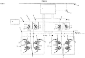
- FIG. 1 shows an anti-skid control 1 in the form of an electronic circuit, which are connected to speed sensors 2 for the wheel speed.
- the speed sensors 2 may be, for example, non-contact sensors which are directed to arranged on wheel axles 3 Poltate 4.
- the signals of the speed sensors 2 are transmitted by signal lines 5 to the anti-skid control 1.
- the anti-skid control 1 controls via control signal lines 6 antiskid valves 7, which are arranged in the brake pressure line 8 between a control or brake valve 9 and the brake cylinder, which is part of a brake 10.
- the brake pressure line 8 passes the brake pressure applied by the control or brake valve 9 to the brake cylinder of the brake 10.
- the brakes 10 are shown on two wheel axles 3 of two bogies 11.
- the anti-skid valve 7 is controlled by the anti-skid control 1 with control signals provided, for example, that during movement of the rail vehicle at applied brake pressure, which is given by the control or brake valve 9 to the brake pressure line 8, in a first switching state, the brake pressure line 8 to the brake cylinder the brake 10 is continuous and an outlet 12 is closed and in a second switching state, in the anti-skid valve 7 is controlled at or before the blocking of a wheel, the brake pressure line 8 is locked or disconnected from the brake cylinder of the brake 10 and an outlet 12 is opened, exits through the brake pressure from the portion of the brake pressure line 8, which the anti-skid valve 7 with the brake cylinder of the brake 10 connects.
- the anti-skid valve 7 is controlled by the anti-skid control 1 with unscheduled control signals, which prevent effective braking at applied brake pressure.
- Unintended control signals are e.g. those that control the anti-skid valve 7 so that the outlet 12 is opened longer than intended and / or the brake pressure line 8 is locked longer than intended, when the control valve 9, the brake pressure line 8 applied with brake pressure. Such unidentified control signals can prevent effective operation of the brake 10.
- the safety control 13 is set up to detect non-provided control signals of the antiskid control 1 and is connected to the control signal line 6 by means of an input for the control signals.
- the input can e.g. be an electrical connection for the control signal line 6.
- the safety controller 13 is arranged in a housing which is attached to the housing of an antiskid valve 7, or in a common housing with the antiskid valve 7.
- the anti-skid control 1 may be connected to a pressure switch 14 for transmitting a signal for the pressure in the main air duct 15 of a rail vehicle.
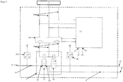
- FIG. 2 shows a safety controller 13 according to the invention, which is connected to the conductors of a control signal line 6.
- the safety controller 13 is set up for the evaluation of control signals and has a breaker 16 which is controlled to interrupt the control signal line 6 to the anti-skid valve 7 when detecting unidentified control signals.
- FIG. 2 the switching state is shown in which the breaker 16 interrupts the control signal line, so that the non-slip valve 7 connected thereto is electrically separated from the antiskid control 1 and is de-energized.
- the anti-skid valve 7 has, in the embodiment shown here, two simple valves, namely a first valve 17, which in the brake pressure line 8 between the control and brake valve 9 and the brake cylinder 18 of a brake 10 is arranged and makes the brake pressure line 8 in the switching position shown throughout and in the alternative switching position, the brake pressure line 8 blocks and thus separates the brake cylinder 18 from the control or brake valve 9.
- a connected to the brake pressure line 8 second valve 19 is connected to the outlet 12, in a first switching state in which the first valve 17 is opened and the brake pressure line 8 from the control or brake valve 9 to the brake cylinder 18 is continuous, the outlet 12th close.
- the second valve 19 connects the brake cylinder 18 to the outlet 12 to release the brake pressure.
- the antiskid valve 7 is controlled by the antiskid controller 1 in the second switching state to prevent or prevent the wheel from locking during braking.
- the anti-skid valve is preferably configured such that the second valve 19 is in the closed position when the first valve 17 is in the open position and the second valve 19 is in the open position when the first valve 17 is in the closed position.
- the FIG. 2 a first pressure sensor 20, which measures the pressure in the brake pressure line 8 between the control or brake valve 9 and the antiskid valve 7, in particular the connection of the first valve 17 and transmits its measuring signal U1 to a first signal input 21 of the safety controller 13.
- the control or brake valve 9 by means of the brake pressure line 8 with the first port 22 of the antiskid valve 7 and in particular its first valve 17 and the first port 22 opposite the second port 23 with the brake cylinder 18.
- a first pressure sensor 20 for example arranged to measure the pressure at the first terminal 22 and for generating a measurement signal U1.
- the FIG. 2 also shows the preferred second pressure sensor 24, which is connected to the second port 23 of the antiskid valve 7 and in particular its first valve 17 and generates a measurement signal U2 for the pressure applied in the brake cylinder 18.
- the second Pressure sensor 24 may be connected to the portion of the brake pressure line 8, which connects the anti-skid valve 7 to the brake cylinder 12.
- the safety controller 13 accordingly preferably has a second signal input 25 for the measurement signal U2 of the second pressure sensor 24.
- the safety controller 13 may be configured to control the breaker 16 to interrupt the control signal line 6 when a brake pressure is determined by the first pressure sensor 20 as an unscheduled control signal and a significantly lower pressure is determined by the second pressure sensor 24 for a period of time that is significantly longer is as a predetermined period of time.
- the predetermined period of time may be the time duration which is provided in the antiskid control 1 for the open position of the antiskid valve 7, in particular of its second valve 19, in which the brake cylinder 18 is connected to the outlet 12.
- a significantly lower pressure e.g. one having a critical pressure deviation, e.g. a pressure deviation of at least 10%, at least 20%, at least 30%, at least 40%, at least 50%, at least 60%, at least 70%, at least 80%, at least 90%, or e.g. up to 100% according to the lack of pressure.
- an unscheduled control signal can consist in that at the brake pressure line 9 by the control or brake valve 9 applied brake pressure and / or a control signal for opening outlet 12 and / or closing the brake pressure line 8 for a longer time than in the anti-skid control 1 is specified, in particular a permanent opening of the outlet 12 and / or a permanent closing of the brake pressure line 8 between the control valve 9 and the brake cylinder 18th
- the opening of the outlet 12 may be determined to be the pressure measured by the second pressure sensor 24 which is significantly less than the pressure measured at the first pressure sensor 20, particularly if this condition is determined for a longer than predetermined period of time.
- the predetermined period of time may be stored in an electronic memory of the safety controller 13, which is arranged to compare the duration of the measured state or signal with the predetermined time duration.
- the predetermined period of time may correspond to the predetermined period of time included in the anti-skid control for controlling the Anti-skid valve is deposited in a position for connecting the brake cylinder to the outlet 12 and, alternatively or additionally, the predetermined period of time may be a predetermined maximum period of time.
Landscapes
- Engineering & Computer Science (AREA)
- Transportation (AREA)
- Mechanical Engineering (AREA)
- Regulating Braking Force (AREA)
Abstract
Description
- Die vorliegende Erfindung betrifft eine Sicherheitssteuerung für eine Druckluftbremse, die eine Gleitschutzsteuerung aufweist, auch als Antiblockiersystem bezeichnet, insbesondere für Schienenfahrzeuge, sowie ein Verfahren zur Steuerung der Druckluftbremse mit Sicherheitssteuerung. Die Erfindung betrifft Druckluftbremsen, die in der Bremsdruckleitung, die durch ein Steuerventil gesteuert mit Druckluft beaufschlagt wird und mit einem Bremszylinder verbunden ist, ein Gleitschutzventil aufweisen, das einerseits die Bremsdruckleitung verschließen bzw. vom Bremszylinder trennen kann, und andererseits den Bremszylinder mit einem Auslass verbinden kann, z.B. über einen Abschnitt der Bremsdruckleitung, um den Bremsdruck aus dem Bremszylinder zu entspannen.
- Das Gleitschutzventil ist z.B. durch eine Gleitschutzsteuerung so gesteuert, dass Bremsdruck, mit dem die Bremsdruckleitung bis in den Bremszylinder durch das Steuerventil beaufschlagt wird, durch den Auslass aus dem Bremszylinder abgelassen wird, wenn in der Gleitschutzsteuerung Signale vorliegen, die ein Blockieren des gebremsten Rads anzeigen. Generell kann das Gleitschutzventil ein Dreiwegeventil oder zwei einfache Ventile aufweisen, die jeweils nur einen Eingang und einen Ausgang haben.
- Die
DE 10344540 B4 beschreibt eine gattungsgemäße, durch Druckluft angetriebene Bremse für Schienenfahrzeuge, bei der zum Verhindern des Blockierens abhängig von der Radgeschwindigkeit der beim Bremsen am Bremszylinder anliegende Bremsdruck durch ein Auslassventil abgesenkt wird, das in der Druckluftleitung zum Bremszylinder angeordnet ist. Das Auslassventil ist durch eine Gleitschutzsteuerung gesteuert, die Signale für die tatsächliche Radgeschwindigkeit von Impulsgebern erhält, um den am Bremszylinder anliegenden Bremsdruck abzusenken, wenn die tatsächliche Radgeschwindigkeit unter der für die Zuggeschwindigkeit proportionalen berechneten Radgeschwindigkeit liegt, um ein Blockieren des Rads zu vermeiden bzw. aufzuheben. - Die Bremse der
DE 10344540 B4 hat den Nachteil, dass bei einem Defekt der Gleitschutzsteuerung das Ablassventil möglicherweise in Offenstellung bleibt und eine Bremsung verhindert, wenn am Bremszylinder Bremsdruck anliegen sollte. - Der Erfindung stellt sich die Aufgabe, eine Schaltung bereitzustellen, mit der bei einer Fehlfunktion der Gleitschutzsteuerung eine wirksame Bremssteuerung ermöglicht wird. Die Schaltung soll insbesondere bei Fehlfunktion einer Gleitschutzsteuerung, die bei normaler Funktion ein Blockieren von Rädern beim Bremsen durch Ablassen von Bremsdruck aus dem Bremszylinder verhindert, die Bremse funktionsfähig machen.
- Die Erfindung löst die Aufgabe mit den Merkmalen der Ansprüche, insbesondere mit einer elektronischen Sicherheitssteuerung für eine Druckluftbremse für Schienenfahrzeuge, die ein Gleitschutzventil aufweist, das zum Verhindern des Blockierens der Räder bei anliegendem Bremsdruck von einer Gleitschutzsteuerung gesteuert ist. Bevorzugt ist das Gleitschutzventil generell eingerichtet und durch die Gleitschutzsteuerung gesteuert, die Bremsdruckleitung zu schließen, so dass der Bremszylinder nicht weiter mit Bremsdruck beaufschlagt wird, und einen Auslass zu öffnen, um den im Bremszylinder vorhandenen Druck entweichen zu lassen, um eine Blockierung des Rads zu beenden oder zu verhindern, und bei fortgesetzt geöffnetem Steuer- oder Bremsventil die weitere Bremsung durch Öffnen der Bremsdruckleitung und Schließen des Auslasses zuzulassen.
- Die Sicherheitssteuerung weist Signaleingänge für die Steuersignale auf, die von einer Gleitschutzsteuerung zum Steuern eines Gleitschutzventils erzeugt werden. Die Steuersignale werden erfindungsgemäß bevorzugt durch eine Steuersignalleitung von der Gleitschutzsteuerung an das Gleitschutzventil übermittelt, wobei die Sicherheitssteuerung Steuersignaleingänge für die Steuersignale aufweist, z.B. einen Anschluss für die Steuersignalleitung. Die Sicherheitssteuerung kann Anschlüsse für die Steuersignale aufweisen, an die das Gleitschutzventil angeschlossen ist. Z.B. kann die Sicherheitssteuerung die Steuersignale der Steuersignalleitung an das Gleitschutzventil weiterleiten oder die Steuersignale über eine Abzweigleitung aufnehmen. Die Sicherheitssteuerung zeichnet sich durch zumindest einen Unterbrecher aus, der an der Steuersignalleitung angeordnet und eingerichtet ist, die Steuersignalleitung zum Gleitschutzventil zu unterbrechen, wenn die Sicherheitssteuerung ein nicht vorgesehenes Steuersignal aufnimmt, das von der Gleitschutzsteuerung erzeugt wurde.
- Durch die Unterbrechung der Steuersignalleitung durch die Sicherheitssteuerung wird die Steuerung des Gleitschutzventils durch die Gleitschutzsteuerung unterbrochen und das Gleitschutzventil wird in einen Schaltzustand gesteuert, in dem die Bremsdruckleitung von einem Steuer- oder Bremsventil durchgehend mit dem Bremszylinder verbunden ist und ein Auslass an der Bremsdruckleitung geschlossen ist. In diesem Schaltzustand kann der Bremsdruck, der von einem Steuer- oder Bremsventil in die Bremsdruckleitung gelassen wird, ohne Beeinflussung durch das Gleitschutzventil auf den Bremszylinder wirken und die Bremsung antreiben. Durch die Unterbrechung der Steuersignalleitung wird ein nicht vorgesehenes Steuersignal der Gleitschutzsteuerung nicht an das Gleitschutzventil geleitet, so dass die Bremse funktionsfähig ist und Bremsdruck auf den Bremszylinder wirkt. Bevorzugt wird die Steuersignalleitung in diesem Schaltzustand durch den Unterbrecher stromlos geschaltet und das Gleitschutzventil ist eingerichtet, im stromlosen Zustand die Bremsdruckleitung durchgehend vom Steuer- oder Bremsventil mit dem Bremszylinder zu verbinden und einen Auslass, der mit der Bremsdruckleitung verbunden ist, zu schließen.
- Ein nicht vorgesehenes Steuersignal ist generell eines, das nicht wie vorgesehen bei anliegendem Bremsdruck das Blockieren des Rads verhindert und im nicht blockierten Zustand des Rads den vom Steuer- oder Bremsventil auf die Bremsdruckleitung aufgegebenen Bremsdruck durch das Gleitschutzventil auf den Bremszylinder leitet und den Auslass schließt. Ein nicht vorgesehenes Steuersignal ist z.B. eines, das bei Fehlfunktion der Gleitschutzsteuerung erzeugt wird, z.B. ein Öffnen des Auslasses und/oder ein Schließen der Bremsdruckleitung für eine längere Zeit, als in der Gleitschutzsteuerung vorgegeben ist, insbesondere ein dauerhaftes Öffnen des Auslasses und/oder ein dauerhaftes Schließen der Bremsdruckleitung. Die Sicherheitssteuerung kann z.B. einen elektronischen Speicher aufweisen, in dem die maximalen Zeiten gespeichert sind, für die die Gleitschutzsteuerung das Gleitschutzventil ansteuert, die Bremsdruckleitung zu unterbrechen bzw. zu sperren und/oder den Auslass zu öffnen. Die Sicherheitssteuerung ist dabei auch eingerichtet, die Zeiten zu bestimmen, für die ein Steuersignal von der Gleitschutzsteuerung erzeugt wird, um das Gleitschutzventil die Bremsdruckleitung unterbrechen bzw. sperren zu lassen und/oder den Auslass öffnen zu lassen, und ist eingerichtet, die für das Steuersignal bestimmten Zeiten mit den maximalen Zeiten zu vergleichen, die in seinem elektronischen Speicher gespeichert sind. Ein nicht vorgesehenes Steuersignal ist z.B. eines, das von der Gleitschutzsteuerung für die Unterbrechung der Bremsdruckleitung und/oder Öffnung des Auslasses für eine längere Zeit erzeugt wird, als die gespeicherte maximale Zeit dafür beträgt.
- Bevorzugt ist die Sicherheitssteuerung dabei eingerichtet, den Unterbrecher anzusteuern, um die Steuersignalleitung zu unterbrechen, wenn durch das Steuerventil Bremsdruck auf die Bremsdruckleitung aufgegeben wird. Alternativ oder zusätzlich zu einem elektronischen Speicher und einer Einrichtung zum Vergleichen gespeicherter maximaler Zeiten mit den für ein Steuersignal aufgenommenen Zeiten, für die das Gleitschutzventil angesteuert wird, um die Bremsdruckleitung zu unterbrechen bzw. sperren und/oder den Auslass zu öffnen, kann die Sicherheitssteuerung einen Signaleingang für ein Messsignal aufweisen, das den Bremsdruck in der Bremsdruckleitung anzeigt und/oder einen Signaleingang für ein Messsignal, das den Druck im Bremszylinder (Bremszylinderdruck) anzeigt. In dieser Ausführung hat die Sicherheitssteuerung den Vorteil, dass sie keine Signalleitung von sich zur Gleitschutzsteuerung aufweist, die zusätzlich zur Steuersignalleitung ist.
- Wenn die Sicherheitssteuerung Steuersignale aufnimmt, die vorgesehen sind, kann die Sicherheitssteuerung den Unterbrecher ansteuern, die Steuersignalleitung wieder herzustellen, bzw. die Unterbrechung zu beenden, so dass das Gleitschutzventil wieder unter die Steuerung durch die Gleitschutzsteuerung kommt.
- Bevorzugt ist die Sicherheitssteuerung an einem Gleitschutzventil angeordnet, das in der Bremsdruckleitung angeordnet ist und bei dem ein Drucksensor an seinem ersten Anschluss angeordnet ist, um ein Messsignal für den Druck in dem daran angeschlossenen Abschnitt der Bremsdruckleitung zu erzeugen, der das Steuer- oder Bremsventil mit dem Gleitschutzventil verbindet. Alternativ oder zusätzlich zu diesem Drucksensor für den Druck in der Bremsdruckleitung am ersten Anschluss des Gleitschutzventils kann das Gleitschutzventil optional einen Drucksensor an seinem dem ersten Anschluss gegenüberliegenden zweiten Anschluss aufweisen, um ein Messsignal für den Druck in dem daran angeschlossenen Abschnitt der Bremsdruckleitung zu erzeugen, der das Gleitschutzventil mit dem Bremszylinder verbindet. In dieser Ausführung ist die Sicherheitssteuerung insbesondere eingerichtet, bei einem Messsignal für den durch das Steuerventil anliegenden Bremsdruck und/oder bei einem Messsignal für die Drucklosigkeit des Bremszylinders den Unterbrecher anzusteuern, die Steuersignalleitung zu unterbrechen. In dieser Ausführung hat die Sicherheitssteuerung den Vorteil, dass sie keine zusätzliche Signalleitung von sich zur Gleitschutzsteuerung aufweist.
- Alternativ oder zusätzlich kann die Sicherheitssteuerung einen Signaleingang für ein Signal aufweisen, das die Betätigung der Bremse anzeigt, z.B. für ein Steuersignal, das das Steuer- bzw. Bremsventil steuert. In dieser Ausführungsform ist die Sicherheitssteuerung eingerichtet, den Unterbrecher zur Unterbrechung der Steuersignalleitung anzusteuern, wenn das Steuersignal für das Steuer- bzw. Bremsventil das Beaufschlagen der Bremsdruckleitung mit Bremsdruck anzeigt und das Gleitschutzventil für eine längere Zeit als vorgesehen von der Gleitschutzsteuerung angesteuert wird, um die Bremsdruckleitung zu unterbrechen bzw. sperren und/oder den Auslass zu öffnen, und/oder wenn das von einem Drucksensor aufgenommene Signal für den Druck im Bremszylinder für längere Zeit als vorgesehen einen Druck anzeigt, der signifikant unterhalb des Bremsdrucks liegt, der vom Steuer- bzw. Bremsventil auf die Bremsdruckleitung gegeben wird. Ein signifikant unterhalb des Bremsdrucks liegender Druck im Bremszylinder ist z.B. einer, der eine kritische Druckabweichung aufweist, z.B. eine Druckabweichung von zumindest 10%, zumindest 20%, zumindest 30%, zumindest 40%, zumindest 50%, zumindest 60%, zumindest 70%, zumindest 80%, zumindest 90%, oder z.B. bis 100% entsprechend der Drucklosigkeit.
- Bevorzugt ist die Gleitschutzsteuerung eingerichtet, das Gleitschutzventil bei anliegendem Bremsdruck abhängig von der Umdrehungsgeschwindigkeit des Rads bzw. der Radachse zu steuern, auf die der Bremszylinder wirkt.
- Die Sicherheitssteuerung ist bevorzugt in einem Gehäuse angeordnet, das als Steuersignaleingänge einen Anschluss für die Steuersignalleitung aufweist, die mit der Gleitschutzsteuerung verbunden ist, und Ausgänge, die mit dem Gleitschutzventil zu verbinden sind, so dass die Sicherheitssteuerung in dem Gehäuse zwischen die Steuersignalleitung und das Gleitschutzventil geschaltet werden kann. Dabei kann das Gehäuse einen Eingang für ein Messsignal des Bremsdrucks und/oder einen Eingang für ein Messsignal des Bremszylinderdrucks aufweisen. Bevorzugt kann die Sicherheitssteuerung in ihrem Gehäuse unmittelbar an einem Gehäuse angebracht sein, in dem das Gleitschutzventil angeordnet ist. Weiter bevorzugt kann die Sicherheitssteuerung mit dem Gleitschutzventil in einem gemeinsamen Gehäuse angeordnet sein.
- Die Erfindung wird nun mit Bezug auf die Figuren beschrieben, die schematisch in
-
Figur 1 eine Bremse mit Gleitschutzsteuerung und Sicherheitssteuerung und -
Figur 2 eine Sicherheitssteuerung zeigen. - In den Figuren bezeichnen gleiche Bezugsziffern funktionsgleiche Elemente.
-
Figur 1 zeigt eine Gleitschutzsteuerung 1 in Form einer elektronischen Schaltung, die mit Geschwindigkeitssensoren 2 für die Radgeschwindigkeit verbunden sind. Die Geschwindigkeitssensoren 2 können z.B. berührungsfreie Sensoren sein, die auf an Radachsen 3 angeordnete Polräder 4 gerichtet sind. Die Signale der Geschwindigkeitssensoren 2 werden durch Signalleitungen 5 an die Gleitschutzsteuerung 1 übermittelt. Die Gleitschutzsteuerung 1 steuert über Steuersignalleitungen 6 Gleitschutzventile 7, die in der Bremsdruckleitung 8 zwischen einem Steuer- bzw. Bremsventil 9 und dem Bremszylinder, der Bestandteil einer Bremse 10 ist, angeordnet sind. Die Bremsdruckleitung 8 leitet den vom Steuer- bzw. Bremsventil 9 aufgegebenen Bremsdruck an den Bremszylinder der Bremse 10. Vorliegend sind die Bremsen 10 an jeweils zwei Radachsen 3 zweier Drehgestelle 11 gezeigt. - Das Gleitschutzventil 7 wird von der Gleitschutzsteuerung 1 mit vorgesehenen Steuersignalen z.B. so gesteuert, dass bei Bewegung des Schienenfahrzeugs bei anliegendem Bremsdruck, der durch das Steuer- bzw. Bremsventil 9 auf die Bremsdruckleitung 8 gegeben wird, in einem ersten Schaltzustand die Bremsdruckleitung 8 bis zum Bremszylinder der Bremse 10 durchgängig ist und ein Auslass 12 verschlossen ist und in einem zweiten Schaltzustand, in den das Gleitschutzventil 7 bei oder vor dem Blockieren eines Rads gesteuert wird, die Bremsdruckleitung 8 gesperrt bzw. vom Bremszylinder der Bremse 10 getrennt wird und ein Auslass 12 geöffnet wird, durch den Bremsdruck aus dem Abschnitt der Bremsdruckleitung 8 austritt, der das Gleitschutzventil 7 mit dem Bremszylinder der Bremse 10 verbindet.
- Bei einer Störung der Gleitschutzsteuerung 1 wird das Gleitschutzventil 7 von der Gleitschutzsteuerung 1 mit nicht vorgesehenen Steuersignalen gesteuert, die eine wirksame Bremsung bei anliegendem Bremsdruck verhindern. Nicht vorgesehene Steuersignale sind z.B. solche, die das Gleitschutzventil 7 so steuern, dass der Auslass 12 länger als vorgesehen geöffnet ist und/oder die Bremsdruckleitung 8 länger als vorgesehen gesperrt wird, wenn das Steuerventil 9 die Bremsdruckleitung 8 mit Bremsdruck beaufschlagt. Solche nicht vorgesehenen Steuersignale können eine wirksame Betätigung der Bremse 10 verhindern.
- Die erfindungsgemäße Sicherheitssteuerung 13 ist eingerichtet, nicht vorgesehene Steuersignale der Gleitschutzsteuerung 1 zu erkennen und ist mittels eines Eingangs für die Steuersignale mit der Steuersignalleitung 6 verbunden. Der Eingang kann z.B. ein elektrischer Anschluss für die Steuersignalleitung 6 sein.
- Entsprechend einer bevorzugten Ausführungsform ist die Sicherheitssteuerung 13 in einem Gehäuse angeordnet, das an dem Gehäuse eines Gleitschutzventils 7 angebracht ist, oder in einem gemeinsamen Gehäuse mit dem Gleitschutzventil 7.
- Generell kann die Gleitschutzsteuerung 1 mit einem Druckschalter 14 zur Übermittlung eines Signals für den Druck in der Hauptluftleitung 15 eines Schienenfahrzeugs verbunden sein.
- Die
Figur 2 zeigt eine erfindungsgemäße Sicherheitssteuerung 13, die mit den Leitern einer Steuersignalleitung 6 verbunden ist. Die Sicherheitssteuerung 13 ist zur Auswertung von Steuersignalen eingerichtet und weist einen Unterbrecher 16 auf, der gesteuert ist, bei Feststellen von nicht vorgesehenen Steuersignalen die Steuersignalleitung 6 zum Gleitschutzventil 7 zu unterbrechen. InFigur 2 ist der Schaltzustand gezeigt, in dem der Unterbrecher 16 die Steuersignalleitung unterbricht, so dass das daran angeschlossene Gleitschutzventil 7 von der Gleitschutzsteuerung 1 elektrisch getrennt ist und stromlos geschaltet ist. Das Gleitschutzventil 7 weist in der hier gezeigten Ausführungsform zwei einfache Ventile auf, nämlich ein erstes Ventil 17, das in der Bremsdruckleitung 8 zwischen dem Steuer- bzw. Bremsventil 9 und dem Bremszylinder 18 einer Bremse 10 angeordnet ist und die Bremsdruckleitung 8 in der gezeigten Schaltstellung durchgängig macht und in der alternativen Schaltstellung die Bremsdruckleitung 8 sperrt und so den Bremszylinder 18 vom Steuer- bzw. Bremsventil 9 trennt. Ein an der Bremsdruckleitung 8 angeschlossenes zweites Ventil 19 ist mit dem Auslass 12 verbunden, um in einem ersten Schaltzustand, in dem das erste Ventil 17 geöffnet ist und die Bremsdruckleitung 8 vom Steuer- bzw. Bremsventil 9 zum Bremszylinder 18 durchgängig ist, den Auslass 12 zu schließen. In einem zweiten Schaltzustand, in dem das erste Ventil 17 den Bremszylinder 18 von dem Steuer- bzw. Bremsventil 9 trennt, verbindet das zweite Ventil 19 den Bremszylinder 18 mit dem Auslass 12, um den Bremsdruck abzulassen. Das Gleitschutzventil 7 wird von der Gleitschutzsteuerung 1 in den zweiten Schaltzustand gesteuert, um ein Blockieren des Rads beim Bremsen zu verhindern oder diesem vorzubeugen. - Generell ist das Gleitschutzventil bevorzugt eingerichtet, dass das zweite Ventil 19 in Geschlossenstellung ist, wenn das erste Ventil 17 in Offenstellung ist und das zweite Ventil 19 in Offenstellung ist, wenn das erste Ventil 17 in Geschlossenstellung ist.
- Entsprechend der bevorzugten Ausführungsform zeigt die
Figur 2 einen ersten Drucksensor 20, der den Druck in der Bremsdruckleitung 8 zwischen dem Steuer- bzw. Bremsventil 9 und dem Gleitschutzventil 7, insbesondere dem Anschluss des ersten Ventils 17 misst und sein Messsignal U1 an einen ersten Signaleingang 21 der Sicherheitssteuerung 13 übermittelt. - Insbesondere in der Ausführung des Gleitschutzventils 7 als ein einfaches erstes Ventil 17 in der Bremsdruckleitung 8 und ein einfaches zweites Ventil 19, das zwischen der Bremsdruckleitung 8 und dem Auslass 12 angeordnet ist, ist das Steuer- bzw. Bremsventil 9 mittels der Bremsdruckleitung 8 mit dem ersten Anschluss 22 des Gleitschutzventils 7 und insbesondere dessen ersten Ventils 17 verbunden und der dem ersten Anschluss 22 gegenüberliegende zweite Anschluss 23 mit dem Bremszylinder 18. Entsprechend ist ein erster Drucksensor 20 z.B. angeordnet, den Druck am ersten Anschluss 22 zu messen und dafür ein Messsignal U1 zu erzeugen.
- Die
Figur 2 zeigt auch den bevorzugten zweiten Drucksensor 24, der am zweiten Anschluss 23 des Gleitschutzventils 7 und insbesondere dessen ersten Ventils 17 angeschlossen ist und ein Messsignal U2 für den Druck erzeugt, der im Bremszylinder 18 anliegt. Der zweite Drucksensor 24 kann an dem Abschnitt der Bremsdruckleitung 8 angeschlossen sein, der das Gleitschutzventil 7 mit dem Bremszylinder 12 verbindet. Die Sicherheitssteuerung 13 weist entsprechend bevorzugt einen zweiten Signaleingang 25 für das Messsignal U2 des zweiten Drucksensors 24 auf. - Die Sicherheitssteuerung 13 kann eingerichtet sein, den Unterbrecher 16 zur Unterbrechung der Steuersignalleitung 6 anzusteuern, wenn als nicht vorgesehenes Steuersignal ein Bremsdruck durch den ersten Drucksensor 20 bestimmt wird und durch den zweiten Drucksensor 24 ein signifikant niedrigerer Druck für eine Zeitdauer bestimmt wird, die signifikant länger ist als eine vorbestimmte Zeitdauer. Dabei kann die vorbestimmte Zeitdauer die Zeitdauer sein, die in der Gleitschutzsteuerung 1 für die Offenstellung des Gleitschutzventils 7, insbesondere von dessen zweitem Ventil 19 vorgesehen ist, in der der Bremszylinder 18 mit dem Auslass 12 verbunden ist. Ein signifikant niedrigerer Druck z.B. einer, der eine kritische Druckabweichung aufweist, z.B. eine Druckabweichung von zumindest 10%, zumindest 20%, zumindest 30%, zumindest 40%, zumindest 50%, zumindest 60%, zumindest 70%, zumindest 80%, zumindest 90%, oder z.B. bis 100% entsprechend der Drucklosigkeit.
- Generell kann ein nicht vorgesehenes Steuersignal darin bestehen, dass bei an der Bremsdruckleitung 9 durch das Steuer- bzw. Bremsventil 9 anliegendem Bremsdruck und/oder einem Steuersignal für das Öffnen Auslasses 12 und/oder ein Schließen der Bremsdruckleitung 8 für eine längere Zeit, als in der Gleitschutzsteuerung 1 vorgegeben ist, insbesondere ein dauerhaftes Öffnen des Auslasses 12 und/oder ein dauerhaftes Schließen der Bremsdruckleitung 8 zwischen Steuerventil 9 und Bremszylinder 18.
- Das Öffnen des Auslasses 12 kann als Druck bestimmt sein, der durch den zweiten Drucksensor 24 gemessen wird und der signifikant unter dem am ersten Drucksensor 20 gemessenen Druck liegt, insbesondere wenn dieser Zustand für eine länger als vorbestimmte Zeitdauer bestimmt wird.
- Die vorbestimmte Zeitdauer kann in einem elektronischen Speicher der Sicherheitssteuerung 13 gespeichert sein, die eingerichtet ist, die Zeitdauer des gemessenen Zustands bzw. Signals mit der vorbestimmten Zeitdauer zu vergleichen. Die vorbestimmte Zeitdauer kann z.B. der vorbestimmten Zeitdauer entsprechen, die in der Gleitschutzsteuerung für das Steuern des Gleitschutzventils in eine Stellung zum Verbinden des Bremszylinders mit dem Auslass 12 hinterlegt ist und alternativ oder zusätzlich kann die vorbestimmte Zeitdauer eine vorgegebene maximale Zeitdauer sein.
-
- 1
- Gleitschutzsteuerung
- 2
- Geschwindigkeitssensoren
- 3
- Radachsen
- 4
- Polrad
- 5
- Signalleitung
- 6
- Steuersignalleitung
- 7
- Gleitschutzventil
- 8
- Bremsdruckleitung
- 9
- Steuer- oder Bremsventil
- 10
- Bremse
- 11
- Drehgestell
- 12
- Auslass
- 13
- Sicherheitssteuerung
- 14
- Druckschalter
- 15
- Hauptluftleitung
- 16
- Unterbrecher
- 17
- erstes Ventil
- 18
- Bremszylinder
- 19
- zweites Ventil
- 20
- erster Drucksensor
- 21
- erster Signaleingang
- 22
- erster Anschluss
- 23
- zweiter Anschluss
- 24
- zweiter Drucksensor
- 25
- zweiter Signaleingang
- U1
- Messsignal am ersten Anschluss
- U2
- Messsignal am zweiten Anschluss
Claims (12)
- Sicherheitssteuerung (13) für eine gesteuerte Druckluftbremse, insbesondere für Schienenfahrzeuge, mit Steuersignaleingängen für Steuersignale, die durch eine Steuersignalleitung (6) von einer Gleitschutzsteuerung (1) an ein in einer Bremsdruckleitung (8) angeordnetes Gleitschutzventil (7) geleitet werden, und mit zumindest einem Unterbrecher (16), der an der Steuersignalleitung (6) angeordnet ist, wobei die Sicherheitssteuerung (13) eingerichtet ist, die Steuersignale auszuwerten und bei nicht vorgesehenen Steuersignalen den Unterbrecher (16) zu steuern, um die Steuersignalleitung (6) zu unterbrechen.
- Sicherheitssteuerung (13) nach Anspruch 1, dadurch gekennzeichnet, dass sie einen Eingang für ein Steuersignal eines Steuerventils (9) für den Bremsdruck aufweist und zur Auswertung der Steuersignale eingerichtet ist, so dass sie ein Steuersignal für anliegenden Bremsdruck in Verbindung mit einem länger als vorbestimmt andauernden Steuersignal für eine Stellung des Gleitschutzventils (7), in der Bremsdruck abgelassen wird und/oder die Bremsdruckleitung (8) abgesperrt wird, als nicht vorgesehenes Steuersignal erkennt.
- Sicherheitssteuerung (13) nach einem der voranstehenden Ansprüche, dadurch gekennzeichnet, dass sie einen Signaleingang (21) für ein Messsignal (U1) eines Bremsdrucks aufweist, der in der Bremsdruckleitung (8) an einem ersten Anschluss (22) des Gleitschutzventils (7) anliegt, und einen Signaleingang (25) für ein Messsignal (U2) des Bremszylinderdrucks, der zwischen einem dem ersten Anschluss (22) gegenüberliegenden zweiten Anschluss (23) des Gleitschutzventils (7) und einem Bremszylinder (18) anliegt, wobei die Sicherheitssteuerung (13) zur Auswertung der Steuersignale eingerichtet ist, ein Messsignal (U1) für anliegenden Bremsdruck in Verbindung mit einem Messsignal (U2) für eine kritische Druckabweichung zwischen dem zweiten Anschluss (23) des Gleitschutzventils (7) und dem Bremszylinder (18) für länger als eine vorbestimmte Zeit als nicht vorgesehenes Steuersignal zu erkennen.
- Sicherheitssteuerung (13) nach einem der voranstehenden Ansprüche, dadurch gekennzeichnet, dass ein Bremsdruck der von einem Steuerventil (9) für den Bremsdruck auf die Bremsdruckleitung (8) gegebene Druck ist.
- Sicherheitssteuerung (13) nach einem der voranstehenden Ansprüche, dadurch gekennzeichnet, dass das Gleitschutzventil (7) eingerichtet ist, bei Stromlosigkeit durch Unterbrechung der Steuersignalleitung (6) eine Ventilstellung einzunehmen, in der die Bremsdruckleitung (8) zum Bremszylinder (18) durchgängig ist und ein Auslass (12) zum Ablassen des Bremsdrucks verschlossen ist.
- Sicherheitssteuerung (13) nach einem der voranstehenden Ansprüche, dadurch gekennzeichnet, dass das Gleitschutzventil (7) in einem ersten Schaltzustand die Bremsdruckleitung (8) bis zum Bremszylinder (18) durchgängig macht und einen Auslass (12) verschließt und in einem zweiten Schaltzustand die Bremsdruckleitung (8) zum Bremszylinder (18) verschließt und den Bremszylinder (18) mit einem Auslass (12) verbindet.
- Sicherheitssteuerung (13) nach einem der voranstehenden Ansprüche, dadurch gekennzeichnet, dass die Gleitschutzsteuerung (1) eingerichtet ist, bei anliegendem Bremsdruck in Abhängigkeit von der Umdrehungsgeschwindigkeit eines vom Bremszylinder (18) gebremsten Rads das Gleitschutzventil (7) zu steuern.
- Sicherheitssteuerung (13) nach einem der voranstehenden Ansprüche, dadurch gekennzeichnet, dass sie in einem Gehäuse angeordnet ist, das als Steuersignaleingänge für Steuersignale einen Anschluss für eine Steuersignalleitung (6) aufweist, die an einer Gleitschutzsteuerung (1) angeschlossen ist, und das mit einem Gleitschutzventil (7) verbindbare Ausgänge für Steuersignale aufweist, wobei der zumindest eine Unterbrecher (16) in dem Gehäuse zwischen dem Anschluss für die Steuersignalleitung (6) und den Ausgängen angeordnet ist.
- Sicherheitssteuerung (13) nach einem der Ansprüche 2 bis 8, dadurch gekennzeichnet, dass sie von einem Gehäuse eingefasst ist, das an einem Gehäuse befestigbar ist, das ein Gleitschutzventil (7) und einen Drucksensor (20) in der Bremsdruckleitung zur Erzeugung eines Messsignals (U1) des Bremsdrucks, der in der Bremsdruckleitung (8) an einem ersten Anschluss (22) des Gleitschutzventils (7) anliegt, enthält.
- Sicherheitssteuerung (13) nach einem der Ansprüche 2 bis 9, dadurch gekennzeichnet, dass sie von einem Gehäuse eingefasst ist, das an einem Gehäuse befestigbar ist, das ein Gleitschutzventil (7) und einen Drucksensor (24) an dem dem ersten Anschluss (22) gegenüberliegenden zweiten Anschluss (23) des Gleitschutzventils (7) zur Erzeugung eines Messsignals (U2) des Bremszylinderdrucks aufweist.
- Sicherheitssteuerung (13) nach einem der voranstehenden Ansprüche, dadurch gekennzeichnet, dass das Gleitschutzventil (7) ein in der Bremsdruckleitung (8) angeordnetes erstes Ventil (17) und ein zwischen dem erstem Ventil (17) und einem Bremszylinder (18) mit der Bremsdruckleitung (8) verbundenes zweites Ventil (19) enthält, das in einem ersten Schaltzustand die Bremsleitung (8) abdichtet und in einem zweiten Schaltzustand den Bremszylinder (18) mit dem Auslass (12) verbindet.
- Verfahren zur Sicherung der Funktion einer gesteuerten Druckluftbremse für Schienenfahrzeuge, bei dem eine Gleitschutzsteuerung (1) bei anliegendem Bremsdruck in Abhängigkeit von der Umdrehungsgeschwindigkeit eines vom Bremszylinder (18) gebremsten Rads ein Gleitschutzventil (7) mit Steuersignalen steuert, die durch eine Steuersignalleitung an das Gleitschutzventil (7) übermittelt werden, gekennzeichnet durch das Unterbrechen der Steuersignalleitung (6) durch eine Sicherheitssteuerung (13) nach einem der voranstehenden Ansprüche.
Priority Applications (1)
| Application Number | Priority Date | Filing Date | Title |
|---|---|---|---|
| PL17150580T PL3190018T3 (pl) | 2016-01-07 | 2017-01-06 | Sterownik bezpieczeństwa do hamulca pneumatycznego ze sterownikiem zabezpieczenia przed poślizgiem |
Applications Claiming Priority (1)
| Application Number | Priority Date | Filing Date | Title |
|---|---|---|---|
| DE102016200114.0A DE102016200114A1 (de) | 2016-01-07 | 2016-01-07 | Sicherheitssteuerung für eine Druckluftbremse mit Gleitschutzsteuerung |
Publications (2)
| Publication Number | Publication Date |
|---|---|
| EP3190018A1 true EP3190018A1 (de) | 2017-07-12 |
| EP3190018B1 EP3190018B1 (de) | 2018-01-17 |
Family
ID=57755213
Family Applications (1)
| Application Number | Title | Priority Date | Filing Date |
|---|---|---|---|
| EP17150580.3A Active EP3190018B1 (de) | 2016-01-07 | 2017-01-06 | Sicherheitssteuerung für eine druckluftbremse mit gleitschutzsteuerung |
Country Status (5)
| Country | Link |
|---|---|
| EP (1) | EP3190018B1 (de) |
| DE (1) | DE102016200114A1 (de) |
| ES (1) | ES2665806T3 (de) |
| HU (1) | HUE038616T2 (de) |
| PL (1) | PL3190018T3 (de) |
Citations (4)
| Publication number | Priority date | Publication date | Assignee | Title |
|---|---|---|---|---|
| DE4137546A1 (de) * | 1991-11-12 | 1993-05-13 | Mannesmann Ag | Verfahren und einrichtung zum bestimmen der tatsaechlichen fahrgeschwindigkeit, insbesondere bei schienenfahrzeugen |
| DE19512804C1 (de) * | 1995-04-05 | 1996-08-08 | Lucas Ind Plc | Hydraulikaggregat für eine blockiergeschützte Fahrzeugbremsanlage |
| DE10344540B4 (de) | 2003-09-25 | 2007-11-08 | Kes Keschwari Electronic Systems Gmbh & Co. Kg | Verfahren zum Bestimmen der tatsächlichen Fahrgeschwindigkeit von Schienenfahrzeugen |
| DE102012014885A1 (de) * | 2012-07-26 | 2014-01-30 | Knorr-Bremse Systeme für Schienenfahrzeuge GmbH | Bremssteuereinrichtung für ein Schienenfahrzeug |
-
2016
- 2016-01-07 DE DE102016200114.0A patent/DE102016200114A1/de not_active Withdrawn
-
2017
- 2017-01-06 EP EP17150580.3A patent/EP3190018B1/de active Active
- 2017-01-06 ES ES17150580.3T patent/ES2665806T3/es active Active
- 2017-01-06 PL PL17150580T patent/PL3190018T3/pl unknown
- 2017-01-06 HU HUE17150580A patent/HUE038616T2/hu unknown
Patent Citations (4)
| Publication number | Priority date | Publication date | Assignee | Title |
|---|---|---|---|---|
| DE4137546A1 (de) * | 1991-11-12 | 1993-05-13 | Mannesmann Ag | Verfahren und einrichtung zum bestimmen der tatsaechlichen fahrgeschwindigkeit, insbesondere bei schienenfahrzeugen |
| DE19512804C1 (de) * | 1995-04-05 | 1996-08-08 | Lucas Ind Plc | Hydraulikaggregat für eine blockiergeschützte Fahrzeugbremsanlage |
| DE10344540B4 (de) | 2003-09-25 | 2007-11-08 | Kes Keschwari Electronic Systems Gmbh & Co. Kg | Verfahren zum Bestimmen der tatsächlichen Fahrgeschwindigkeit von Schienenfahrzeugen |
| DE102012014885A1 (de) * | 2012-07-26 | 2014-01-30 | Knorr-Bremse Systeme für Schienenfahrzeuge GmbH | Bremssteuereinrichtung für ein Schienenfahrzeug |
Also Published As
| Publication number | Publication date |
|---|---|
| PL3190018T3 (pl) | 2018-07-31 |
| HUE038616T2 (hu) | 2018-10-29 |
| DE102016200114A1 (de) | 2017-07-13 |
| EP3190018B1 (de) | 2018-01-17 |
| ES2665806T3 (es) | 2018-04-27 |
Similar Documents
| Publication | Publication Date | Title |
|---|---|---|
| DE102008029310B4 (de) | Überwachungseinrichtung zur Überwachung von Systemen eines Fahrzeugs | |
| DE2840262C2 (de) | ||
| DE19510755C2 (de) | Bremsanordnung für ein mehrere Bremssysteme aufweisendes schienengebundenes Triebfahrzeug | |
| EP3172078B1 (de) | Stromübertragungssystem und verfahren zum betreiben eines stromübertragungssystems | |
| EP3371017B1 (de) | Pneumatische bremseinrichtung für ein nutzfahrzeug | |
| DE102008045712A1 (de) | Elektropneumatische Bremseinrichtung sowie Verfahren zum Betrieb derselben | |
| EP2753512B1 (de) | Bremssteuereinrichtung für eine bremsanlage, bremsanlage, schienenfahrzeug sowie verfahren zum betreiben einer bremsanlage | |
| DE19638377B4 (de) | Steuer/Regelsystem für das Verhalten eines Fahrzeugs | |
| EP3113993B1 (de) | Verfahren zur steuerung einer bremsanlage eines schienenfahrzeugs | |
| EP3371020B1 (de) | Pneumatische bremseinrichtung | |
| EP3650292A1 (de) | Verfahren zur funktionsüberprüfung eines druckmittelbetriebenen elektronischen bremssystems eines fahrzeugs | |
| WO2017093224A1 (de) | Druckluftbremseinrichtung für ein schienenfahrzeug mit einer direkten, elektropneumatischen bremse | |
| DE10004086A1 (de) | Bremsanlage für Fahrzeuge, insbesondere Nutzfahrzeuge | |
| DE102008032715B4 (de) | Elektropneumatische Bremseinrichtung eines Schienenfahrzeuges | |
| DE2723847B2 (de) | Überwachungseinrichtung für eine blockiergeschützte Fahrzeugbremsanlage | |
| EP0205928A1 (de) | Schaltungsaordnung zur Erkennung eines Leitungsbruches bei einer elektropneumatischen Fahrzeugbremsanlage mit vom Zugfahrzeug gesteuerter Anhängerbremse | |
| EP0442050B1 (de) | Elektronisch geregelte Druckmittel-Bremseinrichtung | |
| EP3190018B1 (de) | Sicherheitssteuerung für eine druckluftbremse mit gleitschutzsteuerung | |
| EP1646545A1 (de) | Bremsvorrichtung eines schienenfahrzeugs | |
| DE10209913C1 (de) | Notbremsüberbrückungseinrichtung zur Ansteuerung von elektropneumatischen Zugbremseinrichtungen in Triebfahrzeugen und Steuerwagen mit konventioneller Bremstechnik | |
| DE3146563C2 (de) | Anordnung zum Überwachen der Trennung zweier oder mehr zu einem Zug gekuppelter Fahrzeuge | |
| DE102010023565B4 (de) | Elektrisch betreibbare Bremse, elektrische Gleitschutzanordnung für eine solche Bremse und Verfahren zum Betätigen einer elektrisch betreibbaren Bremse | |
| DE10010221B4 (de) | Verfahren und Schienenfahrzeug zum Testen der Bremsen eines Schienenfahrzeuges | |
| EP1195286A2 (de) | Verfahren zum Überwachen einer Bremse und Verfahren zum Bremsen einer Lokomotive | |
| DE4136978A1 (de) | Druckluft-bremsanlage fuer fahrzeuge |
Legal Events
| Date | Code | Title | Description |
|---|---|---|---|
| PUAI | Public reference made under article 153(3) epc to a published international application that has entered the european phase |
Free format text: ORIGINAL CODE: 0009012 |
|
| STAA | Information on the status of an ep patent application or granted ep patent |
Free format text: STATUS: THE APPLICATION HAS BEEN PUBLISHED |
|
| AK | Designated contracting states |
Kind code of ref document: A1 Designated state(s): AL AT BE BG CH CY CZ DE DK EE ES FI FR GB GR HR HU IE IS IT LI LT LU LV MC MK MT NL NO PL PT RO RS SE SI SK SM TR |
|
| AX | Request for extension of the european patent |
Extension state: BA ME |
|
| STAA | Information on the status of an ep patent application or granted ep patent |
Free format text: STATUS: REQUEST FOR EXAMINATION WAS MADE |
|
| 17P | Request for examination filed |
Effective date: 20170803 |
|
| GRAP | Despatch of communication of intention to grant a patent |
Free format text: ORIGINAL CODE: EPIDOSNIGR1 |
|
| STAA | Information on the status of an ep patent application or granted ep patent |
Free format text: STATUS: GRANT OF PATENT IS INTENDED |
|
| INTG | Intention to grant announced |
Effective date: 20171020 |
|
| GRAS | Grant fee paid |
Free format text: ORIGINAL CODE: EPIDOSNIGR3 |
|
| GRAA | (expected) grant |
Free format text: ORIGINAL CODE: 0009210 |
|
| STAA | Information on the status of an ep patent application or granted ep patent |
Free format text: STATUS: THE PATENT HAS BEEN GRANTED |
|
| RBV | Designated contracting states (corrected) |
Designated state(s): AL AT BE BG CH CY CZ DE DK EE ES FI FR GB GR HR HU IE IS IT LI LT LU LV MC MK MT NL NO PL PT RO RS SE SI SK SM TR |
|
| AK | Designated contracting states |
Kind code of ref document: B1 Designated state(s): AL AT BE BG CH CY CZ DE DK EE ES FI FR GB GR HR HU IE IS IT LI LT LU LV MC MK MT NL NO PL PT RO RS SE SI SK SM TR |
|
| REG | Reference to a national code |
Ref country code: GB Ref legal event code: FG4D Free format text: NOT ENGLISH |
|
| REG | Reference to a national code |
Ref country code: CH Ref legal event code: EP |
|
| REG | Reference to a national code |
Ref country code: IE Ref legal event code: FG4D Free format text: LANGUAGE OF EP DOCUMENT: GERMAN |
|
| REG | Reference to a national code |
Ref country code: AT Ref legal event code: REF Ref document number: 964191 Country of ref document: AT Kind code of ref document: T Effective date: 20180215 |
|
| REG | Reference to a national code |
Ref country code: DE Ref legal event code: R096 Ref document number: 502017000002 Country of ref document: DE |
|
| REG | Reference to a national code |
Ref country code: ES Ref legal event code: FG2A Ref document number: 2665806 Country of ref document: ES Kind code of ref document: T3 Effective date: 20180427 |
|
| REG | Reference to a national code |
Ref country code: SE Ref legal event code: TRGR |
|
| REG | Reference to a national code |
Ref country code: NL Ref legal event code: MP Effective date: 20180117 |
|
| REG | Reference to a national code |
Ref country code: LT Ref legal event code: MG4D |
|
| PG25 | Lapsed in a contracting state [announced via postgrant information from national office to epo] |
Ref country code: NL Free format text: LAPSE BECAUSE OF FAILURE TO SUBMIT A TRANSLATION OF THE DESCRIPTION OR TO PAY THE FEE WITHIN THE PRESCRIBED TIME-LIMIT Effective date: 20180117 |
|
| PG25 | Lapsed in a contracting state [announced via postgrant information from national office to epo] |
Ref country code: FI Free format text: LAPSE BECAUSE OF FAILURE TO SUBMIT A TRANSLATION OF THE DESCRIPTION OR TO PAY THE FEE WITHIN THE PRESCRIBED TIME-LIMIT Effective date: 20180117 Ref country code: NO Free format text: LAPSE BECAUSE OF FAILURE TO SUBMIT A TRANSLATION OF THE DESCRIPTION OR TO PAY THE FEE WITHIN THE PRESCRIBED TIME-LIMIT Effective date: 20180417 Ref country code: CY Free format text: LAPSE BECAUSE OF FAILURE TO SUBMIT A TRANSLATION OF THE DESCRIPTION OR TO PAY THE FEE WITHIN THE PRESCRIBED TIME-LIMIT Effective date: 20180117 Ref country code: HR Free format text: LAPSE BECAUSE OF FAILURE TO SUBMIT A TRANSLATION OF THE DESCRIPTION OR TO PAY THE FEE WITHIN THE PRESCRIBED TIME-LIMIT Effective date: 20180117 Ref country code: LT Free format text: LAPSE BECAUSE OF FAILURE TO SUBMIT A TRANSLATION OF THE DESCRIPTION OR TO PAY THE FEE WITHIN THE PRESCRIBED TIME-LIMIT Effective date: 20180117 |
|
| PG25 | Lapsed in a contracting state [announced via postgrant information from national office to epo] |
Ref country code: BG Free format text: LAPSE BECAUSE OF FAILURE TO SUBMIT A TRANSLATION OF THE DESCRIPTION OR TO PAY THE FEE WITHIN THE PRESCRIBED TIME-LIMIT Effective date: 20180417 Ref country code: GR Free format text: LAPSE BECAUSE OF FAILURE TO SUBMIT A TRANSLATION OF THE DESCRIPTION OR TO PAY THE FEE WITHIN THE PRESCRIBED TIME-LIMIT Effective date: 20180418 Ref country code: RS Free format text: LAPSE BECAUSE OF FAILURE TO SUBMIT A TRANSLATION OF THE DESCRIPTION OR TO PAY THE FEE WITHIN THE PRESCRIBED TIME-LIMIT Effective date: 20180117 Ref country code: IS Free format text: LAPSE BECAUSE OF FAILURE TO SUBMIT A TRANSLATION OF THE DESCRIPTION OR TO PAY THE FEE WITHIN THE PRESCRIBED TIME-LIMIT Effective date: 20180517 Ref country code: LV Free format text: LAPSE BECAUSE OF FAILURE TO SUBMIT A TRANSLATION OF THE DESCRIPTION OR TO PAY THE FEE WITHIN THE PRESCRIBED TIME-LIMIT Effective date: 20180117 |
|
| PG25 | Lapsed in a contracting state [announced via postgrant information from national office to epo] |
Ref country code: MT Free format text: LAPSE BECAUSE OF FAILURE TO SUBMIT A TRANSLATION OF THE DESCRIPTION OR TO PAY THE FEE WITHIN THE PRESCRIBED TIME-LIMIT Effective date: 20180117 |
|
| REG | Reference to a national code |
Ref country code: DE Ref legal event code: R097 Ref document number: 502017000002 Country of ref document: DE |
|
| REG | Reference to a national code |
Ref country code: HU Ref legal event code: AG4A Ref document number: E038616 Country of ref document: HU |
|
| PG25 | Lapsed in a contracting state [announced via postgrant information from national office to epo] |
Ref country code: AL Free format text: LAPSE BECAUSE OF FAILURE TO SUBMIT A TRANSLATION OF THE DESCRIPTION OR TO PAY THE FEE WITHIN THE PRESCRIBED TIME-LIMIT Effective date: 20180117 Ref country code: RO Free format text: LAPSE BECAUSE OF FAILURE TO SUBMIT A TRANSLATION OF THE DESCRIPTION OR TO PAY THE FEE WITHIN THE PRESCRIBED TIME-LIMIT Effective date: 20180117 Ref country code: EE Free format text: LAPSE BECAUSE OF FAILURE TO SUBMIT A TRANSLATION OF THE DESCRIPTION OR TO PAY THE FEE WITHIN THE PRESCRIBED TIME-LIMIT Effective date: 20180117 |
|
| PLBE | No opposition filed within time limit |
Free format text: ORIGINAL CODE: 0009261 |
|
| STAA | Information on the status of an ep patent application or granted ep patent |
Free format text: STATUS: NO OPPOSITION FILED WITHIN TIME LIMIT |
|
| PG25 | Lapsed in a contracting state [announced via postgrant information from national office to epo] |
Ref country code: DK Free format text: LAPSE BECAUSE OF FAILURE TO SUBMIT A TRANSLATION OF THE DESCRIPTION OR TO PAY THE FEE WITHIN THE PRESCRIBED TIME-LIMIT Effective date: 20180117 Ref country code: SK Free format text: LAPSE BECAUSE OF FAILURE TO SUBMIT A TRANSLATION OF THE DESCRIPTION OR TO PAY THE FEE WITHIN THE PRESCRIBED TIME-LIMIT Effective date: 20180117 Ref country code: SM Free format text: LAPSE BECAUSE OF FAILURE TO SUBMIT A TRANSLATION OF THE DESCRIPTION OR TO PAY THE FEE WITHIN THE PRESCRIBED TIME-LIMIT Effective date: 20180117 |
|
| 26N | No opposition filed |
Effective date: 20181018 |
|
| PGFP | Annual fee paid to national office [announced via postgrant information from national office to epo] |
Ref country code: MK Payment date: 20190103 Year of fee payment: 3 |
|
| PG25 | Lapsed in a contracting state [announced via postgrant information from national office to epo] |
Ref country code: MC Free format text: LAPSE BECAUSE OF FAILURE TO SUBMIT A TRANSLATION OF THE DESCRIPTION OR TO PAY THE FEE WITHIN THE PRESCRIBED TIME-LIMIT Effective date: 20180117 |
|
| PG25 | Lapsed in a contracting state [announced via postgrant information from national office to epo] |
Ref country code: LU Free format text: LAPSE BECAUSE OF NON-PAYMENT OF DUE FEES Effective date: 20190106 |
|
| REG | Reference to a national code |
Ref country code: BE Ref legal event code: MM Effective date: 20190131 |
|
| REG | Reference to a national code |
Ref country code: IE Ref legal event code: MM4A |
|
| PG25 | Lapsed in a contracting state [announced via postgrant information from national office to epo] |
Ref country code: BE Free format text: LAPSE BECAUSE OF NON-PAYMENT OF DUE FEES Effective date: 20190131 |
|
| PG25 | Lapsed in a contracting state [announced via postgrant information from national office to epo] |
Ref country code: IE Free format text: LAPSE BECAUSE OF NON-PAYMENT OF DUE FEES Effective date: 20190106 |
|
| PG25 | Lapsed in a contracting state [announced via postgrant information from national office to epo] |
Ref country code: TR Free format text: LAPSE BECAUSE OF FAILURE TO SUBMIT A TRANSLATION OF THE DESCRIPTION OR TO PAY THE FEE WITHIN THE PRESCRIBED TIME-LIMIT Effective date: 20180117 |
|
| PG25 | Lapsed in a contracting state [announced via postgrant information from national office to epo] |
Ref country code: PT Free format text: LAPSE BECAUSE OF FAILURE TO SUBMIT A TRANSLATION OF THE DESCRIPTION OR TO PAY THE FEE WITHIN THE PRESCRIBED TIME-LIMIT Effective date: 20180517 |
|
| PG25 | Lapsed in a contracting state [announced via postgrant information from national office to epo] |
Ref country code: SI Free format text: LAPSE BECAUSE OF FAILURE TO SUBMIT A TRANSLATION OF THE DESCRIPTION OR TO PAY THE FEE WITHIN THE PRESCRIBED TIME-LIMIT Effective date: 20180117 |
|
| PGFP | Annual fee paid to national office [announced via postgrant information from national office to epo] |
Ref country code: HU Payment date: 20221210 Year of fee payment: 7 |
|
| PG25 | Lapsed in a contracting state [announced via postgrant information from national office to epo] |
Ref country code: HU Free format text: LAPSE BECAUSE OF NON-PAYMENT OF DUE FEES Effective date: 20240107 |
|
| PG25 | Lapsed in a contracting state [announced via postgrant information from national office to epo] |
Ref country code: HU Free format text: LAPSE BECAUSE OF NON-PAYMENT OF DUE FEES Effective date: 20240107 |
|
| PGFP | Annual fee paid to national office [announced via postgrant information from national office to epo] |
Ref country code: GB Payment date: 20251103 Year of fee payment: 10 |
|
| PGFP | Annual fee paid to national office [announced via postgrant information from national office to epo] |
Ref country code: FR Payment date: 20251103 Year of fee payment: 10 |
|
| PGFP | Annual fee paid to national office [announced via postgrant information from national office to epo] |
Ref country code: SE Payment date: 20251208 Year of fee payment: 10 |
|
| PGFP | Annual fee paid to national office [announced via postgrant information from national office to epo] |
Ref country code: CZ Payment date: 20251208 Year of fee payment: 10 |
|
| PGFP | Annual fee paid to national office [announced via postgrant information from national office to epo] |
Ref country code: PL Payment date: 20251208 Year of fee payment: 10 |
|
| REG | Reference to a national code |
Ref country code: CH Ref legal event code: U11 Free format text: ST27 STATUS EVENT CODE: U-0-0-U10-U11 (AS PROVIDED BY THE NATIONAL OFFICE) Effective date: 20260201 |
|
| PGFP | Annual fee paid to national office [announced via postgrant information from national office to epo] |
Ref country code: ES Payment date: 20260203 Year of fee payment: 10 |
|
| PGFP | Annual fee paid to national office [announced via postgrant information from national office to epo] |
Ref country code: DE Payment date: 20251201 Year of fee payment: 10 |
|
| PGFP | Annual fee paid to national office [announced via postgrant information from national office to epo] |
Ref country code: AT Payment date: 20251201 Year of fee payment: 10 |
|
| PGFP | Annual fee paid to national office [announced via postgrant information from national office to epo] |
Ref country code: IT Payment date: 20251201 Year of fee payment: 10 |
|
| PGFP | Annual fee paid to national office [announced via postgrant information from national office to epo] |
Ref country code: CH Payment date: 20260201 Year of fee payment: 10 |