EP3189019B1 - Wabenstrukturfilter mit mehrschichtigen verschlussstopfen und verfahren zu dessen herstellung - Google Patents
Wabenstrukturfilter mit mehrschichtigen verschlussstopfen und verfahren zu dessen herstellung Download PDFInfo
- Publication number
- EP3189019B1 EP3189019B1 EP15763734.9A EP15763734A EP3189019B1 EP 3189019 B1 EP3189019 B1 EP 3189019B1 EP 15763734 A EP15763734 A EP 15763734A EP 3189019 B1 EP3189019 B1 EP 3189019B1
- Authority
- EP
- European Patent Office
- Prior art keywords
- layer
- honeycomb body
- face
- composition
- patty
- Prior art date
- Legal status (The legal status is an assumption and is not a legal conclusion. Google has not performed a legal analysis and makes no representation as to the accuracy of the status listed.)
- Active
Links
- 238000004519 manufacturing process Methods 0.000 title description 5
- 239000000203 mixture Substances 0.000 claims description 114
- VYPSYNLAJGMNEJ-UHFFFAOYSA-N Silicium dioxide Chemical compound O=[Si]=O VYPSYNLAJGMNEJ-UHFFFAOYSA-N 0.000 claims description 51
- 239000008119 colloidal silica Substances 0.000 claims description 39
- 239000000919 ceramic Substances 0.000 claims description 35
- 239000002245 particle Substances 0.000 claims description 20
- 239000000843 powder Substances 0.000 claims description 20
- 238000000034 method Methods 0.000 claims description 16
- 239000011148 porous material Substances 0.000 claims description 9
- 239000004215 Carbon black (E152) Substances 0.000 claims description 8
- 229930195733 hydrocarbon Natural products 0.000 claims description 8
- 150000002430 hydrocarbons Chemical class 0.000 claims description 8
- 238000002161 passivation Methods 0.000 claims description 5
- 238000009826 distribution Methods 0.000 claims description 4
- 238000003825 pressing Methods 0.000 claims description 4
- 238000006722 reduction reaction Methods 0.000 claims description 3
- 238000006243 chemical reaction Methods 0.000 claims 1
- 230000008595 infiltration Effects 0.000 claims 1
- 238000001764 infiltration Methods 0.000 claims 1
- 238000007789 sealing Methods 0.000 claims 1
- 239000010410 layer Substances 0.000 description 140
- 241000264877 Hippospongia communis Species 0.000 description 72
- 239000000463 material Substances 0.000 description 65
- 239000011230 binding agent Substances 0.000 description 54
- 239000004568 cement Substances 0.000 description 17
- 239000011149 active material Substances 0.000 description 11
- 239000003349 gelling agent Substances 0.000 description 9
- 239000010408 film Substances 0.000 description 8
- 239000007789 gas Substances 0.000 description 8
- 239000007788 liquid Substances 0.000 description 8
- 229910021536 Zeolite Inorganic materials 0.000 description 6
- MCMNRKCIXSYSNV-UHFFFAOYSA-N Zirconium dioxide Chemical compound O=[Zr]=O MCMNRKCIXSYSNV-UHFFFAOYSA-N 0.000 description 6
- 230000008901 benefit Effects 0.000 description 6
- KRKNYBCHXYNGOX-UHFFFAOYSA-N citric acid Chemical compound OC(=O)CC(O)(C(O)=O)CC(O)=O KRKNYBCHXYNGOX-UHFFFAOYSA-N 0.000 description 6
- HNPSIPDUKPIQMN-UHFFFAOYSA-N dioxosilane;oxo(oxoalumanyloxy)alumane Chemical compound O=[Si]=O.O=[Al]O[Al]=O HNPSIPDUKPIQMN-UHFFFAOYSA-N 0.000 description 6
- -1 polyethylene Polymers 0.000 description 6
- 239000007787 solid Substances 0.000 description 6
- 239000003981 vehicle Substances 0.000 description 6
- 239000010457 zeolite Substances 0.000 description 6
- 239000003054 catalyst Substances 0.000 description 5
- 239000012792 core layer Substances 0.000 description 5
- 239000000945 filler Substances 0.000 description 5
- 239000000126 substance Substances 0.000 description 5
- 239000000758 substrate Substances 0.000 description 5
- XLYOFNOQVPJJNP-UHFFFAOYSA-N water Substances O XLYOFNOQVPJJNP-UHFFFAOYSA-N 0.000 description 5
- 239000010419 fine particle Substances 0.000 description 4
- 229920000609 methyl cellulose Polymers 0.000 description 4
- 239000001923 methylcellulose Substances 0.000 description 4
- 239000012044 organic layer Substances 0.000 description 4
- 239000004014 plasticizer Substances 0.000 description 4
- 229910000505 Al2TiO5 Inorganic materials 0.000 description 3
- 239000004698 Polyethylene Substances 0.000 description 3
- 229920002678 cellulose Polymers 0.000 description 3
- 239000001913 cellulose Substances 0.000 description 3
- CETPSERCERDGAM-UHFFFAOYSA-N ceric oxide Chemical compound O=[Ce]=O CETPSERCERDGAM-UHFFFAOYSA-N 0.000 description 3
- 229910000422 cerium(IV) oxide Inorganic materials 0.000 description 3
- 239000011362 coarse particle Substances 0.000 description 3
- 229910052878 cordierite Inorganic materials 0.000 description 3
- JSKIRARMQDRGJZ-UHFFFAOYSA-N dimagnesium dioxido-bis[(1-oxido-3-oxo-2,4,6,8,9-pentaoxa-1,3-disila-5,7-dialuminabicyclo[3.3.1]nonan-7-yl)oxy]silane Chemical compound [Mg++].[Mg++].[O-][Si]([O-])(O[Al]1O[Al]2O[Si](=O)O[Si]([O-])(O1)O2)O[Al]1O[Al]2O[Si](=O)O[Si]([O-])(O1)O2 JSKIRARMQDRGJZ-UHFFFAOYSA-N 0.000 description 3
- 239000012530 fluid Substances 0.000 description 3
- 239000011521 glass Substances 0.000 description 3
- 239000002241 glass-ceramic Substances 0.000 description 3
- 238000010438 heat treatment Methods 0.000 description 3
- 239000010954 inorganic particle Substances 0.000 description 3
- 150000002500 ions Chemical class 0.000 description 3
- 239000000314 lubricant Substances 0.000 description 3
- 239000011159 matrix material Substances 0.000 description 3
- 238000012986 modification Methods 0.000 description 3
- 230000004048 modification Effects 0.000 description 3
- 229920000573 polyethylene Polymers 0.000 description 3
- 230000008569 process Effects 0.000 description 3
- AABBHSMFGKYLKE-SNAWJCMRSA-N propan-2-yl (e)-but-2-enoate Chemical compound C\C=C\C(=O)OC(C)C AABBHSMFGKYLKE-SNAWJCMRSA-N 0.000 description 3
- VTYYLEPIZMXCLO-UHFFFAOYSA-L Calcium carbonate Chemical compound [Ca+2].[O-]C([O-])=O VTYYLEPIZMXCLO-UHFFFAOYSA-L 0.000 description 2
- OKTJSMMVPCPJKN-UHFFFAOYSA-N Carbon Chemical compound [C] OKTJSMMVPCPJKN-UHFFFAOYSA-N 0.000 description 2
- PEDCQBHIVMGVHV-UHFFFAOYSA-N Glycerine Chemical compound OCC(O)CO PEDCQBHIVMGVHV-UHFFFAOYSA-N 0.000 description 2
- 229920003091 Methocel™ Polymers 0.000 description 2
- 239000006057 Non-nutritive feed additive Substances 0.000 description 2
- 239000000853 adhesive Substances 0.000 description 2
- 230000001070 adhesive effect Effects 0.000 description 2
- 238000013459 approach Methods 0.000 description 2
- 230000004888 barrier function Effects 0.000 description 2
- 238000001246 colloidal dispersion Methods 0.000 description 2
- 238000002485 combustion reaction Methods 0.000 description 2
- 230000003247 decreasing effect Effects 0.000 description 2
- 239000002270 dispersing agent Substances 0.000 description 2
- 238000001035 drying Methods 0.000 description 2
- 238000001914 filtration Methods 0.000 description 2
- 230000009969 flowable effect Effects 0.000 description 2
- 239000001866 hydroxypropyl methyl cellulose Substances 0.000 description 2
- 229920003088 hydroxypropyl methyl cellulose Polymers 0.000 description 2
- 235000010979 hydroxypropyl methyl cellulose Nutrition 0.000 description 2
- UFVKGYZPFZQRLF-UHFFFAOYSA-N hydroxypropyl methyl cellulose Chemical compound OC1C(O)C(OC)OC(CO)C1OC1C(O)C(O)C(OC2C(C(O)C(OC3C(C(O)C(O)C(CO)O3)O)C(CO)O2)O)C(CO)O1 UFVKGYZPFZQRLF-UHFFFAOYSA-N 0.000 description 2
- 238000010348 incorporation Methods 0.000 description 2
- MRELNEQAGSRDBK-UHFFFAOYSA-N lanthanum(3+);oxygen(2-) Chemical compound [O-2].[O-2].[O-2].[La+3].[La+3] MRELNEQAGSRDBK-UHFFFAOYSA-N 0.000 description 2
- 230000001050 lubricating effect Effects 0.000 description 2
- 239000003921 oil Substances 0.000 description 2
- 230000035699 permeability Effects 0.000 description 2
- BWHMMNNQKKPAPP-UHFFFAOYSA-L potassium carbonate Chemical compound [K+].[K+].[O-]C([O-])=O BWHMMNNQKKPAPP-UHFFFAOYSA-L 0.000 description 2
- 239000002994 raw material Substances 0.000 description 2
- 230000009467 reduction Effects 0.000 description 2
- 239000006254 rheological additive Substances 0.000 description 2
- 230000035939 shock Effects 0.000 description 2
- 239000000377 silicon dioxide Substances 0.000 description 2
- 238000005245 sintering Methods 0.000 description 2
- 239000000243 solution Substances 0.000 description 2
- 239000010409 thin film Substances 0.000 description 2
- 239000013008 thixotropic agent Substances 0.000 description 2
- 239000004743 Polypropylene Substances 0.000 description 1
- 239000004372 Polyvinyl alcohol Substances 0.000 description 1
- 229910052581 Si3N4 Inorganic materials 0.000 description 1
- 229920002472 Starch Polymers 0.000 description 1
- 239000003522 acrylic cement Substances 0.000 description 1
- 239000002318 adhesion promoter Substances 0.000 description 1
- 229910000287 alkaline earth metal oxide Inorganic materials 0.000 description 1
- PNEYBMLMFCGWSK-UHFFFAOYSA-N aluminium oxide Inorganic materials [O-2].[O-2].[O-2].[Al+3].[Al+3] PNEYBMLMFCGWSK-UHFFFAOYSA-N 0.000 description 1
- CNLWCVNCHLKFHK-UHFFFAOYSA-N aluminum;lithium;dioxido(oxo)silane Chemical compound [Li+].[Al+3].[O-][Si]([O-])=O.[O-][Si]([O-])=O CNLWCVNCHLKFHK-UHFFFAOYSA-N 0.000 description 1
- 150000001450 anions Chemical class 0.000 description 1
- QVGXLLKOCUKJST-UHFFFAOYSA-N atomic oxygen Chemical compound [O] QVGXLLKOCUKJST-UHFFFAOYSA-N 0.000 description 1
- 239000011324 bead Substances 0.000 description 1
- 229910000019 calcium carbonate Inorganic materials 0.000 description 1
- XFWJKVMFIVXPKK-UHFFFAOYSA-N calcium;oxido(oxo)alumane Chemical compound [Ca+2].[O-][Al]=O.[O-][Al]=O XFWJKVMFIVXPKK-UHFFFAOYSA-N 0.000 description 1
- 229910052799 carbon Inorganic materials 0.000 description 1
- 238000010531 catalytic reduction reaction Methods 0.000 description 1
- 229920003086 cellulose ether Polymers 0.000 description 1
- 229910052676 chabazite Inorganic materials 0.000 description 1
- 230000008859 change Effects 0.000 description 1
- 238000000576 coating method Methods 0.000 description 1
- 229910000428 cobalt oxide Inorganic materials 0.000 description 1
- 230000008602 contraction Effects 0.000 description 1
- 230000002596 correlated effect Effects 0.000 description 1
- 230000000875 corresponding effect Effects 0.000 description 1
- 238000003745 diagnosis Methods 0.000 description 1
- KZHJGOXRZJKJNY-UHFFFAOYSA-N dioxosilane;oxo(oxoalumanyloxy)alumane Chemical compound O=[Si]=O.O=[Si]=O.O=[Al]O[Al]=O.O=[Al]O[Al]=O.O=[Al]O[Al]=O KZHJGOXRZJKJNY-UHFFFAOYSA-N 0.000 description 1
- 230000000694 effects Effects 0.000 description 1
- 239000003344 environmental pollutant Substances 0.000 description 1
- 229910000174 eucryptite Inorganic materials 0.000 description 1
- 238000010304 firing Methods 0.000 description 1
- 235000013312 flour Nutrition 0.000 description 1
- 239000000446 fuel Substances 0.000 description 1
- 238000001879 gelation Methods 0.000 description 1
- 235000011187 glycerol Nutrition 0.000 description 1
- 239000010439 graphite Substances 0.000 description 1
- 229910002804 graphite Inorganic materials 0.000 description 1
- 238000011065 in-situ storage Methods 0.000 description 1
- 230000003993 interaction Effects 0.000 description 1
- UEGPKNKPLBYCNK-UHFFFAOYSA-L magnesium acetate Chemical compound [Mg+2].CC([O-])=O.CC([O-])=O UEGPKNKPLBYCNK-UHFFFAOYSA-L 0.000 description 1
- 239000011654 magnesium acetate Substances 0.000 description 1
- 229940069446 magnesium acetate Drugs 0.000 description 1
- 235000011285 magnesium acetate Nutrition 0.000 description 1
- 239000000155 melt Substances 0.000 description 1
- 229910052751 metal Inorganic materials 0.000 description 1
- 239000002184 metal Substances 0.000 description 1
- 150000002739 metals Chemical class 0.000 description 1
- 230000005012 migration Effects 0.000 description 1
- 238000013508 migration Methods 0.000 description 1
- 238000002156 mixing Methods 0.000 description 1
- 229910052863 mullite Inorganic materials 0.000 description 1
- 229910000510 noble metal Inorganic materials 0.000 description 1
- 230000003287 optical effect Effects 0.000 description 1
- 239000011368 organic material Substances 0.000 description 1
- 229910052760 oxygen Inorganic materials 0.000 description 1
- 239000001301 oxygen Substances 0.000 description 1
- SOQBVABWOPYFQZ-UHFFFAOYSA-N oxygen(2-);titanium(4+) Chemical compound [O-2].[O-2].[Ti+4] SOQBVABWOPYFQZ-UHFFFAOYSA-N 0.000 description 1
- 238000012856 packing Methods 0.000 description 1
- 229910052763 palladium Inorganic materials 0.000 description 1
- 239000011087 paperboard Substances 0.000 description 1
- 230000002093 peripheral effect Effects 0.000 description 1
- 239000004033 plastic Substances 0.000 description 1
- 229920003023 plastic Polymers 0.000 description 1
- 229910052697 platinum Inorganic materials 0.000 description 1
- 231100000719 pollutant Toxicity 0.000 description 1
- 229920000728 polyester Polymers 0.000 description 1
- 229920001155 polypropylene Polymers 0.000 description 1
- 229920002635 polyurethane Polymers 0.000 description 1
- 239000004814 polyurethane Substances 0.000 description 1
- 229920002451 polyvinyl alcohol Polymers 0.000 description 1
- 229910000027 potassium carbonate Inorganic materials 0.000 description 1
- 239000010970 precious metal Substances 0.000 description 1
- 230000008929 regeneration Effects 0.000 description 1
- 238000011069 regeneration method Methods 0.000 description 1
- 238000000518 rheometry Methods 0.000 description 1
- 150000003839 salts Chemical class 0.000 description 1
- 239000003566 sealing material Substances 0.000 description 1
- HBMJWWWQQXIZIP-UHFFFAOYSA-N silicon carbide Chemical compound [Si+]#[C-] HBMJWWWQQXIZIP-UHFFFAOYSA-N 0.000 description 1
- 229910010271 silicon carbide Inorganic materials 0.000 description 1
- HQVNEWCFYHHQES-UHFFFAOYSA-N silicon nitride Chemical compound N12[Si]34N5[Si]62N3[Si]51N64 HQVNEWCFYHHQES-UHFFFAOYSA-N 0.000 description 1
- 229920002050 silicone resin Polymers 0.000 description 1
- 239000002356 single layer Substances 0.000 description 1
- 239000006104 solid solution Substances 0.000 description 1
- 239000004071 soot Substances 0.000 description 1
- 239000008107 starch Substances 0.000 description 1
- 235000019698 starch Nutrition 0.000 description 1
- 239000011232 storage material Substances 0.000 description 1
- 239000004094 surface-active agent Substances 0.000 description 1
- 239000003784 tall oil Substances 0.000 description 1
- 238000007669 thermal treatment Methods 0.000 description 1
- 239000012815 thermoplastic material Substances 0.000 description 1
- GWEVSGVZZGPLCZ-UHFFFAOYSA-N titanium dioxide Inorganic materials O=[Ti]=O GWEVSGVZZGPLCZ-UHFFFAOYSA-N 0.000 description 1
- 238000011144 upstream manufacturing Methods 0.000 description 1
- 229910052644 β-spodumene Inorganic materials 0.000 description 1
Images


Classifications
-
- F—MECHANICAL ENGINEERING; LIGHTING; HEATING; WEAPONS; BLASTING
- F01—MACHINES OR ENGINES IN GENERAL; ENGINE PLANTS IN GENERAL; STEAM ENGINES
- F01N—GAS-FLOW SILENCERS OR EXHAUST APPARATUS FOR MACHINES OR ENGINES IN GENERAL; GAS-FLOW SILENCERS OR EXHAUST APPARATUS FOR INTERNAL COMBUSTION ENGINES
- F01N3/00—Exhaust or silencing apparatus having means for purifying, rendering innocuous, or otherwise treating exhaust
- F01N3/02—Exhaust or silencing apparatus having means for purifying, rendering innocuous, or otherwise treating exhaust for cooling, or for removing solid constituents of, exhaust
- F01N3/021—Exhaust or silencing apparatus having means for purifying, rendering innocuous, or otherwise treating exhaust for cooling, or for removing solid constituents of, exhaust by means of filters
- F01N3/022—Exhaust or silencing apparatus having means for purifying, rendering innocuous, or otherwise treating exhaust for cooling, or for removing solid constituents of, exhaust by means of filters characterised by specially adapted filtering structure, e.g. honeycomb, mesh or fibrous
- F01N3/0222—Exhaust or silencing apparatus having means for purifying, rendering innocuous, or otherwise treating exhaust for cooling, or for removing solid constituents of, exhaust by means of filters characterised by specially adapted filtering structure, e.g. honeycomb, mesh or fibrous the structure being monolithic, e.g. honeycombs
-
- B—PERFORMING OPERATIONS; TRANSPORTING
- B01—PHYSICAL OR CHEMICAL PROCESSES OR APPARATUS IN GENERAL
- B01D—SEPARATION
- B01D46/00—Filters or filtering processes specially modified for separating dispersed particles from gases or vapours
- B01D46/24—Particle separators, e.g. dust precipitators, using rigid hollow filter bodies
- B01D46/2403—Particle separators, e.g. dust precipitators, using rigid hollow filter bodies characterised by the physical shape or structure of the filtering element
- B01D46/2418—Honeycomb filters
- B01D46/2425—Honeycomb filters characterized by parameters related to the physical properties of the honeycomb structure material
- B01D46/2429—Honeycomb filters characterized by parameters related to the physical properties of the honeycomb structure material of the honeycomb walls or cells
-
- B—PERFORMING OPERATIONS; TRANSPORTING
- B01—PHYSICAL OR CHEMICAL PROCESSES OR APPARATUS IN GENERAL
- B01D—SEPARATION
- B01D46/00—Filters or filtering processes specially modified for separating dispersed particles from gases or vapours
- B01D46/24—Particle separators, e.g. dust precipitators, using rigid hollow filter bodies
- B01D46/2403—Particle separators, e.g. dust precipitators, using rigid hollow filter bodies characterised by the physical shape or structure of the filtering element
- B01D46/2418—Honeycomb filters
- B01D46/2425—Honeycomb filters characterized by parameters related to the physical properties of the honeycomb structure material
- B01D46/24491—Porosity
-
- B—PERFORMING OPERATIONS; TRANSPORTING
- B01—PHYSICAL OR CHEMICAL PROCESSES OR APPARATUS IN GENERAL
- B01D—SEPARATION
- B01D46/00—Filters or filtering processes specially modified for separating dispersed particles from gases or vapours
- B01D46/24—Particle separators, e.g. dust precipitators, using rigid hollow filter bodies
- B01D46/2403—Particle separators, e.g. dust precipitators, using rigid hollow filter bodies characterised by the physical shape or structure of the filtering element
- B01D46/2418—Honeycomb filters
- B01D46/2425—Honeycomb filters characterized by parameters related to the physical properties of the honeycomb structure material
- B01D46/24494—Thermal expansion coefficient, heat capacity or thermal conductivity
-
- B—PERFORMING OPERATIONS; TRANSPORTING
- B01—PHYSICAL OR CHEMICAL PROCESSES OR APPARATUS IN GENERAL
- B01D—SEPARATION
- B01D46/00—Filters or filtering processes specially modified for separating dispersed particles from gases or vapours
- B01D46/24—Particle separators, e.g. dust precipitators, using rigid hollow filter bodies
- B01D46/2403—Particle separators, e.g. dust precipitators, using rigid hollow filter bodies characterised by the physical shape or structure of the filtering element
- B01D46/2418—Honeycomb filters
- B01D46/2451—Honeycomb filters characterized by the geometrical structure, shape, pattern or configuration or parameters related to the geometry of the structure
- B01D46/2459—Honeycomb filters characterized by the geometrical structure, shape, pattern or configuration or parameters related to the geometry of the structure of the plugs
-
- B—PERFORMING OPERATIONS; TRANSPORTING
- B01—PHYSICAL OR CHEMICAL PROCESSES OR APPARATUS IN GENERAL
- B01D—SEPARATION
- B01D46/00—Filters or filtering processes specially modified for separating dispersed particles from gases or vapours
- B01D46/24—Particle separators, e.g. dust precipitators, using rigid hollow filter bodies
- B01D46/2403—Particle separators, e.g. dust precipitators, using rigid hollow filter bodies characterised by the physical shape or structure of the filtering element
- B01D46/2418—Honeycomb filters
- B01D46/2451—Honeycomb filters characterized by the geometrical structure, shape, pattern or configuration or parameters related to the geometry of the structure
- B01D46/2474—Honeycomb filters characterized by the geometrical structure, shape, pattern or configuration or parameters related to the geometry of the structure of the walls along the length of the honeycomb
-
- B—PERFORMING OPERATIONS; TRANSPORTING
- B01—PHYSICAL OR CHEMICAL PROCESSES OR APPARATUS IN GENERAL
- B01D—SEPARATION
- B01D53/00—Separation of gases or vapours; Recovering vapours of volatile solvents from gases; Chemical or biological purification of waste gases, e.g. engine exhaust gases, smoke, fumes, flue gases, aerosols
- B01D53/34—Chemical or biological purification of waste gases
- B01D53/92—Chemical or biological purification of waste gases of engine exhaust gases
- B01D53/94—Chemical or biological purification of waste gases of engine exhaust gases by catalytic processes
- B01D53/9404—Removing only nitrogen compounds
- B01D53/9409—Nitrogen oxides
- B01D53/9413—Processes characterised by a specific catalyst
- B01D53/9418—Processes characterised by a specific catalyst for removing nitrogen oxides by selective catalytic reduction [SCR] using a reducing agent in a lean exhaust gas
-
- B—PERFORMING OPERATIONS; TRANSPORTING
- B01—PHYSICAL OR CHEMICAL PROCESSES OR APPARATUS IN GENERAL
- B01J—CHEMICAL OR PHYSICAL PROCESSES, e.g. CATALYSIS OR COLLOID CHEMISTRY; THEIR RELEVANT APPARATUS
- B01J35/00—Catalysts, in general, characterised by their form or physical properties
- B01J35/50—Catalysts, in general, characterised by their form or physical properties characterised by their shape or configuration
- B01J35/56—Foraminous structures having flow-through passages or channels, e.g. grids or three-dimensional monoliths
-
- B—PERFORMING OPERATIONS; TRANSPORTING
- B28—WORKING CEMENT, CLAY, OR STONE
- B28B—SHAPING CLAY OR OTHER CERAMIC COMPOSITIONS; SHAPING SLAG; SHAPING MIXTURES CONTAINING CEMENTITIOUS MATERIAL, e.g. PLASTER
- B28B11/00—Apparatus or processes for treating or working the shaped or preshaped articles
- B28B11/003—Apparatus or processes for treating or working the shaped or preshaped articles the shaping of preshaped articles, e.g. by bending
- B28B11/006—Making hollow articles or partly closed articles
- B28B11/007—Using a mask for plugging
-
- C—CHEMISTRY; METALLURGY
- C04—CEMENTS; CONCRETE; ARTIFICIAL STONE; CERAMICS; REFRACTORIES
- C04B—LIME, MAGNESIA; SLAG; CEMENTS; COMPOSITIONS THEREOF, e.g. MORTARS, CONCRETE OR LIKE BUILDING MATERIALS; ARTIFICIAL STONE; CERAMICS; REFRACTORIES; TREATMENT OF NATURAL STONE
- C04B28/00—Compositions of mortars, concrete or artificial stone, containing inorganic binders or the reaction product of an inorganic and an organic binder, e.g. polycarboxylate cements
- C04B28/24—Compositions of mortars, concrete or artificial stone, containing inorganic binders or the reaction product of an inorganic and an organic binder, e.g. polycarboxylate cements containing alkyl, ammonium or metal silicates; containing silica sols
-
- C—CHEMISTRY; METALLURGY
- C04—CEMENTS; CONCRETE; ARTIFICIAL STONE; CERAMICS; REFRACTORIES
- C04B—LIME, MAGNESIA; SLAG; CEMENTS; COMPOSITIONS THEREOF, e.g. MORTARS, CONCRETE OR LIKE BUILDING MATERIALS; ARTIFICIAL STONE; CERAMICS; REFRACTORIES; TREATMENT OF NATURAL STONE
- C04B35/00—Shaped ceramic products characterised by their composition; Ceramics compositions; Processing powders of inorganic compounds preparatory to the manufacturing of ceramic products
- C04B35/01—Shaped ceramic products characterised by their composition; Ceramics compositions; Processing powders of inorganic compounds preparatory to the manufacturing of ceramic products based on oxide ceramics
- C04B35/16—Shaped ceramic products characterised by their composition; Ceramics compositions; Processing powders of inorganic compounds preparatory to the manufacturing of ceramic products based on oxide ceramics based on silicates other than clay
- C04B35/18—Shaped ceramic products characterised by their composition; Ceramics compositions; Processing powders of inorganic compounds preparatory to the manufacturing of ceramic products based on oxide ceramics based on silicates other than clay rich in aluminium oxide
- C04B35/195—Alkaline earth aluminosilicates, e.g. cordierite or anorthite
-
- C—CHEMISTRY; METALLURGY
- C04—CEMENTS; CONCRETE; ARTIFICIAL STONE; CERAMICS; REFRACTORIES
- C04B—LIME, MAGNESIA; SLAG; CEMENTS; COMPOSITIONS THEREOF, e.g. MORTARS, CONCRETE OR LIKE BUILDING MATERIALS; ARTIFICIAL STONE; CERAMICS; REFRACTORIES; TREATMENT OF NATURAL STONE
- C04B35/00—Shaped ceramic products characterised by their composition; Ceramics compositions; Processing powders of inorganic compounds preparatory to the manufacturing of ceramic products
- C04B35/622—Forming processes; Processing powders of inorganic compounds preparatory to the manufacturing of ceramic products
- C04B35/626—Preparing or treating the powders individually or as batches ; preparing or treating macroscopic reinforcing agents for ceramic products, e.g. fibres; mechanical aspects section B
- C04B35/63—Preparing or treating the powders individually or as batches ; preparing or treating macroscopic reinforcing agents for ceramic products, e.g. fibres; mechanical aspects section B using additives specially adapted for forming the products, e.g.. binder binders
- C04B35/632—Organic additives
- C04B35/636—Polysaccharides or derivatives thereof
- C04B35/6365—Cellulose or derivatives thereof
-
- C—CHEMISTRY; METALLURGY
- C04—CEMENTS; CONCRETE; ARTIFICIAL STONE; CERAMICS; REFRACTORIES
- C04B—LIME, MAGNESIA; SLAG; CEMENTS; COMPOSITIONS THEREOF, e.g. MORTARS, CONCRETE OR LIKE BUILDING MATERIALS; ARTIFICIAL STONE; CERAMICS; REFRACTORIES; TREATMENT OF NATURAL STONE
- C04B38/00—Porous mortars, concrete, artificial stone or ceramic ware; Preparation thereof
- C04B38/0006—Honeycomb structures
-
- F—MECHANICAL ENGINEERING; LIGHTING; HEATING; WEAPONS; BLASTING
- F01—MACHINES OR ENGINES IN GENERAL; ENGINE PLANTS IN GENERAL; STEAM ENGINES
- F01N—GAS-FLOW SILENCERS OR EXHAUST APPARATUS FOR MACHINES OR ENGINES IN GENERAL; GAS-FLOW SILENCERS OR EXHAUST APPARATUS FOR INTERNAL COMBUSTION ENGINES
- F01N3/00—Exhaust or silencing apparatus having means for purifying, rendering innocuous, or otherwise treating exhaust
- F01N3/02—Exhaust or silencing apparatus having means for purifying, rendering innocuous, or otherwise treating exhaust for cooling, or for removing solid constituents of, exhaust
- F01N3/021—Exhaust or silencing apparatus having means for purifying, rendering innocuous, or otherwise treating exhaust for cooling, or for removing solid constituents of, exhaust by means of filters
- F01N3/033—Exhaust or silencing apparatus having means for purifying, rendering innocuous, or otherwise treating exhaust for cooling, or for removing solid constituents of, exhaust by means of filters in combination with other devices
- F01N3/035—Exhaust or silencing apparatus having means for purifying, rendering innocuous, or otherwise treating exhaust for cooling, or for removing solid constituents of, exhaust by means of filters in combination with other devices with catalytic reactors, e.g. catalysed diesel particulate filters
-
- B—PERFORMING OPERATIONS; TRANSPORTING
- B01—PHYSICAL OR CHEMICAL PROCESSES OR APPARATUS IN GENERAL
- B01D—SEPARATION
- B01D2255/00—Catalysts
- B01D2255/50—Zeolites
-
- B—PERFORMING OPERATIONS; TRANSPORTING
- B01—PHYSICAL OR CHEMICAL PROCESSES OR APPARATUS IN GENERAL
- B01D—SEPARATION
- B01D2255/00—Catalysts
- B01D2255/90—Physical characteristics of catalysts
- B01D2255/915—Catalyst supported on particulate filters
- B01D2255/9155—Wall flow filters
-
- B—PERFORMING OPERATIONS; TRANSPORTING
- B01—PHYSICAL OR CHEMICAL PROCESSES OR APPARATUS IN GENERAL
- B01D—SEPARATION
- B01D2279/00—Filters adapted for separating dispersed particles from gases or vapours specially modified for specific uses
- B01D2279/30—Filters adapted for separating dispersed particles from gases or vapours specially modified for specific uses for treatment of exhaust gases from IC Engines
-
- C—CHEMISTRY; METALLURGY
- C04—CEMENTS; CONCRETE; ARTIFICIAL STONE; CERAMICS; REFRACTORIES
- C04B—LIME, MAGNESIA; SLAG; CEMENTS; COMPOSITIONS THEREOF, e.g. MORTARS, CONCRETE OR LIKE BUILDING MATERIALS; ARTIFICIAL STONE; CERAMICS; REFRACTORIES; TREATMENT OF NATURAL STONE
- C04B2111/00—Mortars, concrete or artificial stone or mixtures to prepare them, characterised by specific function, property or use
- C04B2111/00474—Uses not provided for elsewhere in C04B2111/00
- C04B2111/00793—Uses not provided for elsewhere in C04B2111/00 as filters or diaphragms
-
- C—CHEMISTRY; METALLURGY
- C04—CEMENTS; CONCRETE; ARTIFICIAL STONE; CERAMICS; REFRACTORIES
- C04B—LIME, MAGNESIA; SLAG; CEMENTS; COMPOSITIONS THEREOF, e.g. MORTARS, CONCRETE OR LIKE BUILDING MATERIALS; ARTIFICIAL STONE; CERAMICS; REFRACTORIES; TREATMENT OF NATURAL STONE
- C04B2111/00—Mortars, concrete or artificial stone or mixtures to prepare them, characterised by specific function, property or use
- C04B2111/00474—Uses not provided for elsewhere in C04B2111/00
- C04B2111/0081—Uses not provided for elsewhere in C04B2111/00 as catalysts or catalyst carriers
-
- C—CHEMISTRY; METALLURGY
- C04—CEMENTS; CONCRETE; ARTIFICIAL STONE; CERAMICS; REFRACTORIES
- C04B—LIME, MAGNESIA; SLAG; CEMENTS; COMPOSITIONS THEREOF, e.g. MORTARS, CONCRETE OR LIKE BUILDING MATERIALS; ARTIFICIAL STONE; CERAMICS; REFRACTORIES; TREATMENT OF NATURAL STONE
- C04B2235/00—Aspects relating to ceramic starting mixtures or sintered ceramic products
- C04B2235/02—Composition of constituents of the starting material or of secondary phases of the final product
- C04B2235/30—Constituents and secondary phases not being of a fibrous nature
- C04B2235/32—Metal oxides, mixed metal oxides, or oxide-forming salts thereof, e.g. carbonates, nitrates, (oxy)hydroxides, chlorides
- C04B2235/3231—Refractory metal oxides, their mixed metal oxides, or oxide-forming salts thereof
- C04B2235/3232—Titanium oxides or titanates, e.g. rutile or anatase
- C04B2235/3234—Titanates, not containing zirconia
- C04B2235/3236—Alkaline earth titanates
-
- C—CHEMISTRY; METALLURGY
- C04—CEMENTS; CONCRETE; ARTIFICIAL STONE; CERAMICS; REFRACTORIES
- C04B—LIME, MAGNESIA; SLAG; CEMENTS; COMPOSITIONS THEREOF, e.g. MORTARS, CONCRETE OR LIKE BUILDING MATERIALS; ARTIFICIAL STONE; CERAMICS; REFRACTORIES; TREATMENT OF NATURAL STONE
- C04B2235/00—Aspects relating to ceramic starting mixtures or sintered ceramic products
- C04B2235/02—Composition of constituents of the starting material or of secondary phases of the final product
- C04B2235/30—Constituents and secondary phases not being of a fibrous nature
- C04B2235/34—Non-metal oxides, non-metal mixed oxides, or salts thereof that form the non-metal oxides upon heating, e.g. carbonates, nitrates, (oxy)hydroxides, chlorides
- C04B2235/3418—Silicon oxide, silicic acids or oxide forming salts thereof, e.g. silica sol, fused silica, silica fume, cristobalite, quartz or flint
-
- C—CHEMISTRY; METALLURGY
- C04—CEMENTS; CONCRETE; ARTIFICIAL STONE; CERAMICS; REFRACTORIES
- C04B—LIME, MAGNESIA; SLAG; CEMENTS; COMPOSITIONS THEREOF, e.g. MORTARS, CONCRETE OR LIKE BUILDING MATERIALS; ARTIFICIAL STONE; CERAMICS; REFRACTORIES; TREATMENT OF NATURAL STONE
- C04B2235/00—Aspects relating to ceramic starting mixtures or sintered ceramic products
- C04B2235/02—Composition of constituents of the starting material or of secondary phases of the final product
- C04B2235/30—Constituents and secondary phases not being of a fibrous nature
- C04B2235/34—Non-metal oxides, non-metal mixed oxides, or salts thereof that form the non-metal oxides upon heating, e.g. carbonates, nitrates, (oxy)hydroxides, chlorides
- C04B2235/3427—Silicates other than clay, e.g. water glass
- C04B2235/3463—Alumino-silicates other than clay, e.g. mullite
- C04B2235/3472—Alkali metal alumino-silicates other than clay, e.g. spodumene, alkali feldspars such as albite or orthoclase, micas such as muscovite, zeolites such as natrolite
-
- C—CHEMISTRY; METALLURGY
- C04—CEMENTS; CONCRETE; ARTIFICIAL STONE; CERAMICS; REFRACTORIES
- C04B—LIME, MAGNESIA; SLAG; CEMENTS; COMPOSITIONS THEREOF, e.g. MORTARS, CONCRETE OR LIKE BUILDING MATERIALS; ARTIFICIAL STONE; CERAMICS; REFRACTORIES; TREATMENT OF NATURAL STONE
- C04B2235/00—Aspects relating to ceramic starting mixtures or sintered ceramic products
- C04B2235/02—Composition of constituents of the starting material or of secondary phases of the final product
- C04B2235/30—Constituents and secondary phases not being of a fibrous nature
- C04B2235/34—Non-metal oxides, non-metal mixed oxides, or salts thereof that form the non-metal oxides upon heating, e.g. carbonates, nitrates, (oxy)hydroxides, chlorides
- C04B2235/3427—Silicates other than clay, e.g. water glass
- C04B2235/3463—Alumino-silicates other than clay, e.g. mullite
- C04B2235/3481—Alkaline earth metal alumino-silicates other than clay, e.g. cordierite, beryl, micas such as margarite, plagioclase feldspars such as anorthite, zeolites such as chabazite
-
- C—CHEMISTRY; METALLURGY
- C04—CEMENTS; CONCRETE; ARTIFICIAL STONE; CERAMICS; REFRACTORIES
- C04B—LIME, MAGNESIA; SLAG; CEMENTS; COMPOSITIONS THEREOF, e.g. MORTARS, CONCRETE OR LIKE BUILDING MATERIALS; ARTIFICIAL STONE; CERAMICS; REFRACTORIES; TREATMENT OF NATURAL STONE
- C04B2235/00—Aspects relating to ceramic starting mixtures or sintered ceramic products
- C04B2235/02—Composition of constituents of the starting material or of secondary phases of the final product
- C04B2235/30—Constituents and secondary phases not being of a fibrous nature
- C04B2235/38—Non-oxide ceramic constituents or additives
- C04B2235/3817—Carbides
- C04B2235/3826—Silicon carbides
-
- C—CHEMISTRY; METALLURGY
- C04—CEMENTS; CONCRETE; ARTIFICIAL STONE; CERAMICS; REFRACTORIES
- C04B—LIME, MAGNESIA; SLAG; CEMENTS; COMPOSITIONS THEREOF, e.g. MORTARS, CONCRETE OR LIKE BUILDING MATERIALS; ARTIFICIAL STONE; CERAMICS; REFRACTORIES; TREATMENT OF NATURAL STONE
- C04B2235/00—Aspects relating to ceramic starting mixtures or sintered ceramic products
- C04B2235/02—Composition of constituents of the starting material or of secondary phases of the final product
- C04B2235/30—Constituents and secondary phases not being of a fibrous nature
- C04B2235/38—Non-oxide ceramic constituents or additives
- C04B2235/3852—Nitrides, e.g. oxynitrides, carbonitrides, oxycarbonitrides, lithium nitride, magnesium nitride
- C04B2235/3873—Silicon nitrides, e.g. silicon carbonitride, silicon oxynitride
-
- C—CHEMISTRY; METALLURGY
- C04—CEMENTS; CONCRETE; ARTIFICIAL STONE; CERAMICS; REFRACTORIES
- C04B—LIME, MAGNESIA; SLAG; CEMENTS; COMPOSITIONS THEREOF, e.g. MORTARS, CONCRETE OR LIKE BUILDING MATERIALS; ARTIFICIAL STONE; CERAMICS; REFRACTORIES; TREATMENT OF NATURAL STONE
- C04B38/00—Porous mortars, concrete, artificial stone or ceramic ware; Preparation thereof
- C04B38/0006—Honeycomb structures
- C04B38/0012—Honeycomb structures characterised by the material used for sealing or plugging (some of) the channels of the honeycombs
-
- F—MECHANICAL ENGINEERING; LIGHTING; HEATING; WEAPONS; BLASTING
- F01—MACHINES OR ENGINES IN GENERAL; ENGINE PLANTS IN GENERAL; STEAM ENGINES
- F01N—GAS-FLOW SILENCERS OR EXHAUST APPARATUS FOR MACHINES OR ENGINES IN GENERAL; GAS-FLOW SILENCERS OR EXHAUST APPARATUS FOR INTERNAL COMBUSTION ENGINES
- F01N2330/00—Structure of catalyst support or particle filter
- F01N2330/06—Ceramic, e.g. monoliths
-
- Y—GENERAL TAGGING OF NEW TECHNOLOGICAL DEVELOPMENTS; GENERAL TAGGING OF CROSS-SECTIONAL TECHNOLOGIES SPANNING OVER SEVERAL SECTIONS OF THE IPC; TECHNICAL SUBJECTS COVERED BY FORMER USPC CROSS-REFERENCE ART COLLECTIONS [XRACs] AND DIGESTS
- Y02—TECHNOLOGIES OR APPLICATIONS FOR MITIGATION OR ADAPTATION AGAINST CLIMATE CHANGE
- Y02T—CLIMATE CHANGE MITIGATION TECHNOLOGIES RELATED TO TRANSPORTATION
- Y02T10/00—Road transport of goods or passengers
- Y02T10/10—Internal combustion engine [ICE] based vehicles
- Y02T10/12—Improving ICE efficiencies
Definitions
- Exemplary embodiments of the present disclosure relate to honeycomb bodies having layered plugs and method of making the same.
- Ceramic wall flow filters can be used for the removal of particulate pollutants from diesel, gasoline, or other combustion engine exhaust streams.
- one approach is to position cured plugs of sealing material at the ends of alternate channels of such structures, which can block direct fluid flow through the channels and force the fluid stream through the porous channel walls of the honeycombs before exiting the filter.
- the after-treatment of exhaust gas from internal combustion engines may use catalysts supported on high-surface area substrates and a catalyzed filter for the removal of carbon soot particles.
- Catalyst supports may be refractory, thermal shock resistant, stable under a range of pO 2 conditions, non-reactive with the catalyst system, and offer low resistance to exhaust gas flow.
- Porous ceramic flow-through honeycomb substrates and wall-flow honeycomb filters (generically referred to herein as honeycomb bodies) may be used in these applications.
- Plug quality is often correlated to the presence of voids in the plugs.
- the presence of voids can be reduced by reducing the amount of water in the plugging composition and/or increasing the particle size of certain batch components in the plugging composition.
- such modifications can lead to plugs with insufficient depth and, hence, insufficient mechanical (or “push out”) strength.
- shorter plugs can provide less back pressure and higher filter volume for the same external geometry, thus reducing the frequency of regenerations and improving fuel economy. Moreover, shorter plugs provide better material utilization, thereby reducing filter manufacturing costs. Accordingly, it may be desirable to provide plugs that are as short as possible while still having the requisite depth to provide sufficient mechanical (or "push out") strength.
- Ceramic cement may be used to form an exterior skin of a honeycomb body which has been machined or "contoured" to a desired dimension, or an exterior skin may be co-extruded with the honeycomb body.
- honeycomb body includes single honeycomb monoliths and honeycomb bodies formed by multiple honeycomb segments that are secured together, such as by using a ceramic cement to form a segmented monolith.
- US 2008/307760 A1 discloses a honeycomb body according the preamble of claim 1.
- Exemplary embodiments of the present disclosure provide a honeycomb body comprising layered plugs.
- Exemplary embodiments of the present disclosure also provide a method of making a honeycomb body comprising layered plugs.
- An exemplary embodiment discloses a porous ceramic honeycomb body, including intersecting walls that form channels extending axially from a first end face to a second end face and plugs to seal at least one of a first portion of the channels at the first end face and a second portion of the channels at the second end face.
- the plugs include a first layer disposed on the walls of respective channels, and a second layer disposed inward toward an axial center of each respective channel on the first layer.
- An exemplary embodiment also discloses a method of plugging a porous ceramic honeycomb body comprising intersecting walls that form channels extending axially from a first end face to a second end face.
- the method includes disposing a first layer patty on a second layer patty, disposing the second layer patty on a support, and pressing the support and the porous ceramic honeycomb body together in an axial direction a predetermined distance to inject the first layer and the second layer in at least one of a first portion of the channels at the first end face and a second portion of the channels at the second end face to form plugs to seal the at least one of the first portion of the channels at the first end face and the second portion of the channels at the second end face.
- the plugs include a first layer of the first layer patty composition disposed on the walls of respective channels, and a second layer of the second layer patty composition disposed inward toward an axial center of each respective channel on the first layer.
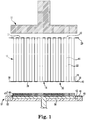
- Honeycomb bodies for solid particulate filters such as the filter body 10 ( FIG. 1 ), and other applications may be formed of a variety of materials including ceramics, glass-ceramics, glasses, metals, and by a variety of methods depending upon the material selected.
- Honeycomb bodies having uniform thin, porous, and interconnected walls for solid particulate filtering applications can be fabricated from plastically formable and sinterable finely divided particles of substances that yield a porous, sintered material after being fired to affect their sintering. Suitable materials include metallics, ceramics, glass-ceramics, and other ceramic based mixtures.
- a method of forming such a ceramic honeycomb monolith from an extruded cordierite material for solid particulate filtering applications is described and claimed, for example, in U.S. Patent No. 5,258,150 co-assigned to the present assignee.
- the covering step can comprise forming the masks 28, 29 according to the processes as described in U.S. Patent Nos. 4,557,773 and 6,673,300 , both co-assigned to the present assignee.
- the first end face 18 is covered by the mask 28 that includes an adhesive backed, pressure-sensitive thin transparent or translucent film formed from a thermoplastic material, for example, a polyester or PET material.
- a thermoplastic material for example, a polyester or PET material.
- other materials such as polyethylene, polypropylene, or polyurethane may be employed.
- Openings are created through the mask corresponding to a selected first subset 26 of cell channels 22 by means of an opening forming tool (for example, a laser) controlled by an optical image analyzer, as described in the references noted above.
- An exemplary mask 28 includes openings 30 positioned so as to coincide with the ends of the first subset 26 of cell channels 22 which are to be charged with plugging material.
- the openings 30 can be suitably sized to expose the open ends of the first subset 26 of the cell channels 22 but not so large as to expose adjacent cell channels 22. It should be noted that larger openings can be provided to expose several adjacent cell channels 22 if desired.
- the mask 28 includes an outer edge 38 and an outer periphery 40 that extends radially outwardly from the outer edge 16 of the first end face 18.
- the body of the mask 28 is adhered to intersecting matrix of walls 14 of the honeycomb structure 10 to hold the mask 28 in position.
- the mask can be adhered with acrylic adhesive or any similar adhesive substance, and, in one embodiment, is applied to the mask 28 before placing the mask on the substrate 10.
- the next step involves forming plugs within the selected subset of cell channels 22.
- a thin film material 42 for example, comprising a PET, polyethylene (plastic) coated paperboard, or the like, is covered by a layered patty 43.
- the layered patty 43 can comprise, for example, a first flat patty of a plugging material 44, comprising a ceramic raw material with an aqueous binder, such as methylcellulose, plasticizer and water, the first flat patty disposed on a second flat patty of a plugging material 45, comprising a ceramic raw material with an aqueous polymeric binder, such as methylcellulose, plasticizer and water.
- Composition of the first and second flat patty materials 44, 45 are described in greater detail below.
- the film material 42 includes an outer periphery 46 and an outer edge 48 each extending outwardly from the outer edge 16 of the substrate body 10, as described below.
- the layered patty 43 of first and second flat patty plugging material 44, 45 is located with respect to the film material 42 such that the outer periphery 46 of the film material 42 is free from the layered plug material 43.
- the first and second flat patty material 44, 45 of the layered patty 43 are provided in the form of a flat patty of a uniform thickness; however, varying thicknesses may also be used.
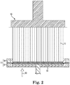
- the film material 42 with the layered plug material 43 thereon is situated upon a servo-driven piston based plugging machine that includes a planar, piston 50 that is surrounded by a clamping assembly 51 having a first clamping portion 52 and a second clamping portion 54 as shown in FIGS. 2 , 3 , and 4 .
- Piston 50 can be shaped to correspond to the honeycomb structure being plugged and can be roughly of a comparable size to the part.
- the first and second clamping portions 52, 54 of the clamping assembly 51 are used to seal the outer periphery 40 of the mask 28 with the outer periphery 46 of the film material 42.
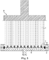
- a force in a direction and as represented by directional arrow 60 is exerted on the film material 42 by the piston 50, thereby forcing the layered plugging material 43 through the openings 30 of the mask 28 and charging the first subset 26 of the cell channels 22 of the honeycomb structure 10 ( FIG. 3 ) and forming the plurality of layered plugs 62.
- a backup plate 55 can be used to anchor the honeycomb body 10.
- the piston 50 is then retracted away from the first end face 18 of the honeycomb structure 10 and the mask 28 and the film material 42 are removed from the end of the filter body 10.
- the filter body 10 may then be removed from within the associated plugging machine.
- the honeycomb structure 10 may be positioned in any orientation during the plugging process, including vertically and horizontally, and further that the second subset 27 of the cell channels 22 located at the second end face 20 may be plugged simultaneously with the first subset 26 of the cell channels 22, thereby significantly decreasing the overall cycle time of the plugging process.
- FIG. 4 the honeycomb body 10 is shown in the plugging machine of FIG. 1 with clamping ring assembly 51 open.
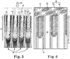
- FIG. 5 is a photograph of a sectioned honeycomb body at an end face showing layered plugs that seal select channels, wherein the channels are sectioned on the 45° angle of square channels according to exemplary embodiments of the present disclosure.
- the channels 22 extent in the axial direction "A" of the honeycomb body 10.
- the shown cross section of an example of multilayer plugs was made using a 2 mm patty of a first cement composition shown as black in the photograph with a 2 mm patty of a second cement composition shown as white in the photograph on top (relative to a plugging direction 60).
- FIG. 6 is a schematic of a sectioned honeycomb body at an end face showing layered plugs that seal select channels, wherein the channels are sectioned on the 90° angle of square channels according to exemplary embodiments of the present disclosure.
- FIG. 6 shows a first layer 64 of first layer patty material 44 disposed on the walls 14 of respective channels 22, and a second layer 66 of second layer patty material 45 disposed inward toward an axial center of each respective channel 22 on the first layer 64. While the illustrated embodiments have described layered plugs 62 seal the select channels 26 at the first end face 18 according to exemplary embodiments of the present disclosure, a second portion of channels 27 are sealed at the second end face 20 in a like manner, the further details of which are omitted here.
- compositions of the first and second flat patty materials 44, 45 that form the first and second plug layers 64, 66 are now described in greater detail.
- the compositions can include a refractory filler having a particle size distribution, an organic binder, an inorganic binder, and a liquid vehicle.
- the refractory filler, the particle size distribution of the refractory filler, the organic binder, and the inorganic binder are selected such that, when the composition including the active material is applied to plug a plurality of channels of the honeycomb body, a plurality of plugs formed therefrom have the desired properties, such as plug depth variability, plug depth, push-out strength, coefficient of thermal expansion (CTE), porosity, permeability, etc.
- the refractory filler can include at least one inorganic powder.
- the inorganic powder may, for example, include a ceramic, i.e., pre-reacted or ceramed, refractory powder.
- the powders can be refractory glass powders, or glass-ceramic powders.
- the inorganic powder batch mixture can comprise any combination of two or more of the aforementioned refractory powders.
- Exemplary refractory powders may include cordierite, mullite, aluminum titanate, silicon carbide, silicon nitride, calcium aluminate, beta-eucryptite, and beta-spodumene.
- the refractory filler can include an active material.
- the active material becomes incorporated in to form the structure of the respective plug layer.
- the active material can be at least one of catalytically active and chemically active and material that is at least one of catalytically active and chemically active is referred to herein as active material.
- the active plug layer is more than simply inactive or non-active material (inert) coated with an active material.
- a batch cement composition that forms a plug layer includes the active material.
- the active material is incorporated in and forms the structure of the active plugs.
- the active material in the active layer can, for example, be a zeolite.
- the active material can be small pore zeolite such as copper-chabazite zeolite (CuCHA), present as catalyst for the selective catalytic reduction of NOx, Cu-exchanged zeolite, Fe-exchanged zeolite, a hydrocarbon-adsorbing zeolite, a high-surface-area material such as alumina, ceria, or zirconia with dispersed precious-metal such as Pt, Pd, or Rh, high surface area titania with vanadia, rhodium-titania, calcium carbonate, HC traps, high surface area material plus a noble metal, high surface area material, on board diagnosis oxygen storage material, ceria:zirconia solid solution material, ceria and zirconia multi-phase material, a three way catalyst (TWC), an alkali earth metal oxide such as potassium carbonate:cobalt oxide:lanthanum oxide, and the like, or
- compositions further comprise a binder component comprised of an inorganic binder.
- the inorganic binder is a gelled inorganic binder such as gelled colloidal silica.
- Other embodiments of an inorganic binder could include a non-gelled colloidal silica, a powdered silica, or a low-temperature glass.
- the incorporation of a gelled inorganic binder may minimize or even prevent the migration of the inorganic binder particles into microcracks of a honeycomb body on which the composition is applied.
- gelled inorganic binder refers to a colloidal dispersion of solid inorganic particles in which the solid inorganic particles form an interconnected network or matrix in combination with a continuous fluid phase, resulting in a viscous semi-rigid material. Further, it should be understood that there can be relative levels or degrees of gelation.
- a gelled inorganic binder as used herein comprises an interconnected network of the dispersed inorganic particles that is sufficient to prevent at least a portion of the inorganic binder particles from migrating into microcracks of a honeycomb structure upon which the composition containing the gelled inorganic binder has been applied.
- the non-gelled colloidal silica can subsequently be gelled by the addition of one or more gelling agents to the composition.
- colloidal silica may be gelled by increasing the ion concentration of the composition.
- colloidal silica can be gelled by altering the pH of the composition.
- Still further embodiments can comprise both increasing the ion concentration and altering the pH of the composition.
- the gelling agent can be used in any amount effective to provide a gelled inorganic binder as described herein.
- Exemplary colloidal silicas can include the Ludox® HS, AS, SK, PW50, and PZ50 available from W.R. Grace & Company, and can be gelled by increasing the ion concentration by addition of salts and/or by changing the pH.
- Ludox® PW50EC a polydisperse colloidal silica
- Ludox® PW50EC has a much broader particle size range than the small silica particle size of Ludox® HS-40.
- Ludox® PW50EC has a particle size range D 50 of approximately 10-100 nm particle size distribution (PSD) as compared to about 12 nm D 50 in Ludox® HS-40.
- PSD particle size distribution
- the larger particles of Ludox® PW50EC do not migrate as easily leaving them dispersed and in the bulk cement mixture.
- the smallest of the particles in the Ludox® PW50EC are still able to migrate and migrate into the substrate.
- Exemplary compositions disclosed herein may further comprise an organic binder.
- the addition of the organic binder component can further contribute to the cohesion and plasticity of the composition prior to firing. This improved cohesion and plasticity can, for example, improve the ability to shape the composition. This can be advantageous when utilizing the composition to form skin coatings or when plugging selected portions (such as the ends) of a honeycomb structural body.
- Exemplary organic binders include cellulose materials.
- Exemplary cellulose materials include cellulose ether binders such as methylcellulose, hydroxypropyl methylcellulose, methylcellulose derivatives, and/or any combinations thereof.
- cellulose materials include combination of methylcellulose and hydroxypropyl methylcellulose.
- the organic binder can be present in the composition as a super addition in an amount in the range of from 0.1 weight percent to 5.0 weight percent of the inorganic powder batch composition, or even in an amount in the range of from 0.5 weight percent to 2.0 weight percent of the inorganic powder batch composition.
- An exemplary liquid vehicle for providing a flowable or paste-like consistency to the disclosed compositions is water, although other liquid vehicles can be used.
- the amount of the liquid vehicle component can vary in order to provide optimum handling properties and compatibility with the other components in the batch mixture.
- the liquid vehicle content is present as a super addition in an amount in the range of from 15% to 60% by weight of the inorganic powder batch composition, or even according to some embodiments can be in the range of from 20% to 50% by weight of the inorganic powder batch mixture. Minimization of liquid components in the compositions can also lead to further reductions in the drying shrinkage of the compositions during the drying process.
- Exemplary compositions disclosed herein can optionally comprise one or more processing aids such as a plasticizer, lubricant, surfactant, sintering aid, rheology modifier, thixotropic agent, dispersing agents, or pore former.
- a plasticizer for use in preparing the plugging composition is glycerine.
- An exemplary lubricant can be a hydrocarbon oil or tall oil.
- Exemplary commercially available lubricants include Liga GS, available from Peter Greven Fett-Chemie and Durasyn® 162 hydrocarbon oil available from Innovene.
- a commercially available thixotropic agent is Benaqua 1000 available from Rheox, Inc.
- a pore former may also be optionally used to produce a desired porosity of the resulting ceramed composition.
- exemplary and non-limiting pore formers can include graphite, starch, polyethylene beads, and/or flour.
- Exemplary dispersing agents that can be used include the NuoSperse® 2000 from Elementis and ZetaSperse® 1200, available from Air Products and Chemicals, Inc.
- the inactive and active components as described above can be mixed together, the inorganic powder batch mixture as described above can be mixed together with the organic binder, followed by the incorporation of the liquid vehicle and inorganic binder components.
- the inorganic binder can be non-gelled or gelled either before or after having been introduced into the composition. If the inorganic binder is to be gelled prior to addition to the composition, the one or more gelling agents can be added to the inorganic binder, such as for example, a colloidal silica. Alternatively, if the inorganic binder is to be gelled after addition to the powder composition, the one or more gelling agents can be introduced directly into the composition.
- any optional processing aids can also be introduced into the composition during or after the liquid addition.
- a rheology modifier such as polyvinyl alcohol can first be mixed with the inorganic binder and, optionally the refractory powder. Once the desired components are combined, the composition can be thoroughly mixed to provide a flowable paste-like consistency to the composition.
- the mixing as described above can be done using a Littleford mixer or a Turbula mixer.
- compositions disclosed herein can be applied to a honeycomb body or structure defining a plurality of cell channels bounded by cell channel walls as described above.
- the compositions disclosed herein can be used as plugging material to plug selected channels of a honeycomb body in order to form a wall flow filter.
- a first portion of the plurality of cell channels can comprise layered plugs sealed to the respective channel walls at or near the upstream inlet end to form outlet cell channels.
- a second portion of the plurality of cell channels can also comprise layered plugs sealed to the respective channel walls at or near the downstream outlet end to form inlet cell channels.
- Other configurations having only one end plugged, as well as partially plugged configurations (having some unplugged channels) are also contemplated.
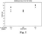
- FIG. 7 is a graphical plot of data showing a comparison of plug strength among a plug composition of gelled colloidal inorganic binder (A), a plug composition of a non-gelled colloidal inorganic binder (P), and a layered plug 62 including a first layer 64 having the composition of gelled colloidal inorganic binder in contact with the channel wall 14 and a second layer 66 having the composition of non-gelled colloidal inorganic binder in the interior according to exemplary embodiments of the present disclosure.
- the exemplary layered plug 62 combination shown in FIG. 7 does not significantly change plug strength from either single layer composition plug on its own.
- FIG. 8 is a graphical plot of data showing a comparison of plug depth among a plug composition of gelled colloidal inorganic binder (A), a plug composition of a non-gelled colloidal inorganic binder (P), and a layered plug 62 including a first layer 64 having the composition of gelled colloidal inorganic binder in contact with the channel wall 14 and a second layer 66 having the composition of non-gelled colloidal inorganic binder in the interior according to exemplary embodiments of the present disclosure.
- the exemplary layered plug 62 combination shown in FIG. 8 results in enhanced plug depth capability compared to either composition separately.
- FIG. 9 is a graphical plot of data showing a comparison of coefficient of thermal expansion (CTE) in an aluminum-titanate honeycomb body among a plug composition of gelled colloidal inorganic binder (A), a plug composition of a non-gelled colloidal inorganic binder (P), and a layered plug 62 including a first layer 64 having the composition of gelled colloidal inorganic binder in contact with the channel wall 14 and a second layer 66 having the composition of non-gelled colloidal inorganic binder in the interior according to exemplary embodiments of the present disclosure.
- the exemplary layered plug 62 combination shown in FIG. 9 results in maintaining the CTE of the gelled cement with a mostly non-gelled interior.
- the composition of the first flat patty material 44 can comprise a passivation material such that when the first plug layer 64 is formed, the passivation material can prevent components of the composition of the second flat patty material 46 from infiltrating into fine pore and microcrack structures of the honeycomb body wall 14.
- the composition of the first flat patty material 44 can comprise a transitory component capable of removal through at least one of thermal treatment and chemical treatment.
- compositions of the first and second flat patty materials 44, 45 that form the first and second plug layers 64, 66 can be any combination of compositions described in Tables 1 and 2.
- Table 1 P A Total Batch Weight (g) 1500 1500 Cordierite 958 864 A4M Methocel® 14.4 F240 Methocel ® 8.6 Ludox® PW-50EC 288 Ludox® HS-40 328 Citric Acid 8.8 Triethanoamine 85% 54.6 Water 240 236 Table 2
- multi-layered plugs exhibited advantages over homogeneous or single-composition plugs.
- Example 1 according to these exemplary embodiments has fine particles of refractory in the wall layer (first layer 64) and coarse refractory particles in the plug core layer (second layer 66).
- Example 1 exhibits an advantage of having low overall packing density, which is good for light-off, while the coarse particles prevent voids and the fine particles provide adhesion by entering wall 14 matrix voids.
- Example 2 exhibited coefficient of thermal expansion (CTE) protection similar to that shown in FIG. 9 .
- Examples 3, 4, 5, and 6 also exhibited CTE protection, but further exhibited good flow in the plug core layer.
- Examples 3, 4, 5, and 6 having different gellants demonstrated that the gellant did not significantly affect these results.
- Example 7 demonstrated that in situ gelling enabled stable rheology during transport and CTE protection upon plugging.
- Example 8 demonstrated a good barrier layer in the wall layer, CTE protection, and the core layer having good flow.
- Example 9 demonstrated a good adhesion layer in the wall layer, CTE protection, and the core layer having good flow.
- An adhesion layer may include silicone resin, colloidal silica, and a material that melts in heat treatment such as a glassy phase.
- Example 10 provided low mass and high bond strength layered plug.
- Examples 11 and 12 provided increased plug depth.
- Examples 13 and 14 provided CTE protection as well as improved chip resistance and improved face gouge resistance.
- Example 15 enables use of high pore former level in the core layer that contacts exhaust gas first in order to provide fast light-off while allowing reduction in overall organic levels by having the wall layer comprised of standard plug cement.
- Examples 16 and 17 provide a plug countersunk into the channel after heat treatment.
- the organic layer for example, can be a wax.
- the organic layer may burn off and leave offset plugs, that is, plugs offset axially into the channels spaced apart from the end face.
- Example 18 provides increased plug depth and CTE protection.
- Example 19 provides a combination of advantages, for example, as described with respect to Examples 1, 3, 15, and 18.
- the first layer 64 of the layered plug 62 can comprise a first property and the second layer 66 can comprise a second property different from the first property.
- the first property may be a first porosity (%P1) and the second property may be a second porosity (%P2).
- the first property may be a first coefficient of thermal expansion (CTE1) and the second property may be a second coefficient of thermal expansion (CTE2).
- the first and second properties are not particularly limited and may include density, permeability, elastic modulus (EMOD), thermal shock parameter (TSP), or any other property that may be desirable to control across the layered plug 62.
- the coefficient of thermal expansion (CTE) of the layered plug 62 may be advantageous to control the coefficient of thermal expansion (CTE) of the layered plug 62 such that the first layer 64 CTE1 more closely matches that of the honeycomb body channel walls 14 (CTE3) than the CTE of the second layer 66 (CTE2).
- the first layer 64 can comprise a first coefficient of thermal expansion (CTE1) and the second layer 66 can comprise a second coefficient of thermal expansion (CTE2) different from the first coefficient of thermal expansion (CTE1), and the walls 14 can comprise a third coefficient of thermal expansion (CTE3).
- the coefficient of thermal expansion relationship may be expressed as CTE3 ⁇ CTE1 ⁇ CTE2. In this way face cracks can be reduced or eliminated while providing faster light-off and increased plug strength and durability.
- CTE protection refers to not pinning microcracks. Expansion and contraction of microcracks in the wall 14 can provide a low CTE3. Pinning of microcracks can raise CTE3.
- the first layer 64 can comprise a first composition that does not pin microcracks in the wall 14 and the second layer 66 can comprise a second composition that may pin microcracks in the wall 14, but because the second layer 66 does not contact the wall 14, CTE3 is not increased.
- the first layer 64 can comprise a first composition that pins microcracks in the wall 14 less than the second layer 66 composition, but because the second layer 66 does not contact the wall 14, CTE3 is increased less than if the second layer 66 does contact the wall 14.
- the first layer 64 can provide a first coefficient of thermal expansion protection (CP1) and the second layer can provide a second coefficient of thermal expansion protection (CP2) different from the first coefficient of thermal expansion (CP1), such that an increase in CTE3 due to localized interaction with the plugging cement composition is reduced or eliminated.
- CP1 first coefficient of thermal expansion protection
- CP2 second coefficient of thermal expansion protection
- the coefficient of thermal expansion protection relationship may be expressed as CP2 ⁇ CP1, where greater coefficient of thermal expansion protection refers to a smaller increase in the wall CTE3. In this way face cracks can be reduced or eliminated while providing faster light-off and increased plug strength and durability.
- the first layer 64 may be a different thickness than the second layer 66.
- the first layer 64 may be between 0% and 10% of the thickness of the second layer 66.
- CTE protection refers to not pinning microcracks.
- the first layer 64 may be greater than or equal to 10% of the thickness of the second layer 66.
- the first layer 64 thickness may be between 10% and 90% of the thickness of the second layer 66.
- the first layer 64 thickness may be between 30% and 70%, or even between 40% and 60% of the thickness of the second layer 66.
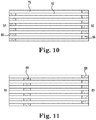
- FIG. 10 is a cross-sectional side view schematic of a honeycomb body 10 having inlet channels 78 plugged at an outlet face 80 and outlet channels 82 plugged at an inlet face 84 according to exemplary embodiments of the present disclosure. At least a portion of the plugs 86 at the inlet face 84 and the plugs 88 at the outlet face 80 may be layered plugs 62.
- FIG. 11 is a cross-sectional side view schematic of a honeycomb body 10 having inlet channels 78 plugged at the outlet face 80 and outlet channel plugs 86 offset from the inlet face 84 according to exemplary embodiments of the present disclosure. At least a portion of the outlet channel plugs 86 countersunk axially (offset) from the inlet face 84 and the inlet channel plugs 88 at the outlet face 80 may be layered plugs 62. The plugs can be countersunk from a few millimeters to a few inches (about 100 mm).
- FIG. 12 is a graphical plot of data showing amount of hydrocarbon accumulated at the outlet of a gas particulate filter (GPF) honeycomb body using the plugging configuration of the exemplary embodiment of FIG. 10 compared to hydrocarbon accumulated at the outlet of a gas particulate filter (GPF) honeycomb body using the plugging configuration of the exemplary embodiment of FIG. 11 with the plugs offset from the inlet face by one inch (2.54 cm).
- GPF gas particulate filter
- FIGS. 13A-13C show a cross-sectional side view of a method of plugging a honeycomb body with offset layered plugs.
- FIG. 13A shows a cross-sectional side view of the honeycomb body 10 having a first end face 84 covered by a mask 28, and a first sacrificial layer disposed on a first layer patty 90 disposed on a second layer patty 92 disposed on a second sacrificial layer patty 94 supported on a piston assembly 50 of a plugging machine according to exemplary embodiments of the present disclosure.
- FIG. 13A shows a cross-sectional side view of the honeycomb body 10 having a first end face 84 covered by a mask 28, and a first sacrificial layer disposed on a first layer patty 90 disposed on a second layer patty 92 disposed on a second sacrificial layer patty 94 supported on a piston assembly 50 of a plugging machine according to exemplary embodiments of the present disclosure.
- FIG. 13B shows the first layer patty 90 material on the channel walls within select channels 26 of the honeycomb body 10 and the second layer patty 92 material inward toward an axial center of each respective channel 82 on the first layer according to exemplary embodiments of the present disclosure.
- the first sacrificial layer 89 material deposits on the walls 14 of the respective channels 82.
- the first layer patty 90 material slides along the first sacrificial layer 89 as piston assembly 50 advances in direction of arrow 60.
- the first layer patty 90 material deposits on the walls 14 after the first sacrificial layer 89 and the second layer patty 92 material deposits on the first layer patty 90 material urged by a second optional sacrificial layer 94 as piston assembly 50 advances in direction of arrow 60.
- the layered plug 62 of each respective channel 82 is shown spaced apart from the first end face 84 by the first and second sacrificial layers 89, 94 according to exemplary embodiments of the present disclosure.
- FIG. 13C shows the layered plug 62 of each respective channel 82 spaced apart from the first end face 84 according to exemplary embodiments of the present disclosure.
- a heat treatment or chemical treatment can be used to remove the material of the first and optional second sacrificial layers 89, 94.
- the material of the first and second sacrificial layers 89, 94 can be an organic material.
- the honeycomb body 10 of FIG. 13C shows a first portion 26 of the channels 22 at the first end face 84 sealed by layered plugs 62 spaced apart from the first end face 84.
- the disclosure is not so limited and can include, for example, a second portion 27 of the channels 22 at the second end face 80 sealed by layered plugs 62 spaced apart from the second end face 80.
- FIG. 14 is a schematic cross-sectional side view showing a honeycomb body 10, a first layer patty 90 disposed on a second layer patty 92 disposed on a third layer patty 96 to be pushed into select channels 26 of honeycomb body 10 at an end face 18 according to exemplary embodiments of the present disclosure.
- the second layer 66 can include more than one layer.
- the more than one layers can be disposed inwardly toward the axial center of the respective channels from the preceding layer as the second layer 66 is disposed inwardly toward the axial center of the respective channels from the first layer 64 in the preceding illustrated embodiments.
- Advantages of exemplary embodiments of the disclosure include control over axially and radially varying plug properties, CTE protection, decreased light-off temperature, low mass to high bond strength, increased plug length, plug depth uniformity, and a combination thereof.
Landscapes
- Chemical & Material Sciences (AREA)
- Engineering & Computer Science (AREA)
- Ceramic Engineering (AREA)
- Chemical Kinetics & Catalysis (AREA)
- Physics & Mathematics (AREA)
- Geometry (AREA)
- Structural Engineering (AREA)
- Materials Engineering (AREA)
- Organic Chemistry (AREA)
- Mechanical Engineering (AREA)
- Manufacturing & Machinery (AREA)
- Combustion & Propulsion (AREA)
- General Engineering & Computer Science (AREA)
- Inorganic Chemistry (AREA)
- Thermal Sciences (AREA)
- Environmental & Geological Engineering (AREA)
- Oil, Petroleum & Natural Gas (AREA)
- Analytical Chemistry (AREA)
- Biomedical Technology (AREA)
- Health & Medical Sciences (AREA)
- General Chemical & Material Sciences (AREA)
- Filtering Materials (AREA)
- Civil Engineering (AREA)
- Catalysts (AREA)
- Porous Artificial Stone Or Porous Ceramic Products (AREA)
- Devices For Post-Treatments, Processing, Supply, Discharge, And Other Processes (AREA)
- Processes For Solid Components From Exhaust (AREA)
- Dispersion Chemistry (AREA)
- Filtering Of Dispersed Particles In Gases (AREA)
Claims (15)
- Poröser keramischer Wabenstrukturkörper (10), umfassend:sich überschneidende Wände (14), die Kanäle (22, 26, 27, 78, 82) bilden, die sich axial von einer ersten Endfläche (18, 84) zu einer zweiten Endfläche (20, 80) erstrecken; undVerschlussstopfen (62, 86, 88) zum Abdichten von mindestens einem von einem ersten Abschnitt der Kanäle (22, 26, 27, 78, 82) an der ersten Endfläche (18, 84) und einem zweiten Abschnitt der Kanäle (22, 26, 27, 78, 82) an der zweiten Endfläche (20, 80),dadurch gekennzeichnet, dass die Verschlussstopfen umfassen:
eine erste Schicht (64), die an den Wänden (14) der jeweiligen Kanäle (22, 26, 27, 78, 82) angeordnet ist, und eine zweite Schicht (66), die nach innen in Richtung einer axialen Mitte jedes jeweiligen Kanals (22, 26, 27, 78, 82) auf der ersten Schicht (64) angeordnet ist. - Poröser keramischer Wabenstrukturkörper nach Anspruch 1, wobei die erste Schicht (64) eine erste Zusammensetzung umfasst und die zweite Schicht (66) eine zweite Zusammensetzung umfasst.
- Poröser keramischer Wabenstrukturkörper nach einem der Ansprüche 1 bis 2, wobei
die erste Zusammensetzung eine erste kolloidale Siliciumdioxidzusammensetzung und eine erste anorganische Pulverkomponente umfasst,
die zweite Zusammensetzung eine zweite kolloidale Siliciumdioxidzusammensetzung und eine zweite anorganische Pulverkomponente umfasst,
wobei die erste anorganische Pulverkomponente eine durchschnittliche Teilchengröße umfasst, die kleiner als die der zweiten anorganischen Pulverkomponente ist, und
wobei die erste kolloidale Siliciumdioxidzusammensetzung eine durchschnittliche Teilchengröße umfasst, die größer als eine durchschnittliche Teilchengröße der zweiten kolloidalen Siliciumdioxidzusammensetzung ist. - Poröser keramischer Wabenstrukturkörper nach einem der Ansprüche 1 bis 3, wobei die erste kolloidale Siliciumdioxidzusammensetzung eine multimodale Teilchengrößenverteilung umfasst und/oder die erste Zusammensetzung eine erste kolloidale Siliciumdioxidzusammensetzung umfasst, die geliert ist, und die zweite Zusammensetzung eine zweite kolloidale Siliciumdioxidzusammensetzung umfasst, die nicht geliert ist.
- Poröser keramischer Wabenstrukturkörper nach einem der Ansprüche 1 bis 4, wobei die erste Zusammensetzung eine Passivierungsschicht umfasst, die in die Wabenstrukturkörperwand (14) absorbiert ist, die zum Verhindern der Infiltration von Komponenten der zweiten Zusammensetzung in feinporige und Mikrorissstrukturen der Wabenstrukturkörperwand (14) konfiguriert ist.
- Poröser keramischer Wabenstrukturkörper nach einem der Ansprüche 1 bis 5, wobei mindestens eine der ersten Schicht (64) und der zweiten Schicht (66) eine katalytisch aktive Komponente oder eine chemisch aktive Komponente der Verschlussstopfenstruktur umfasst.
- Poröser keramischer Wabenstrukturkörper nach einem der Ansprüche 1 bis 6, wobei die katalytisch aktive Komponente in einer NOx-Reduktionsreaktion katalytisch aktiv ist und die chemisch aktive Komponente in der Kohlenwasserstoffreduktionsreaktion chemisch aktiv ist.
- Poröser keramischer Wabenstrukturkörper nach einem der Ansprüche 1 bis 7, wobei die erste Schicht (64) eine erste Porosität umfasst und die zweite Schicht (66) eine zweite Porosität umfasst, die anders als die erste Porosität ist.
- Poröser keramischer Wabenstrukturkörper nach einem der Ansprüche 1 bis 8,
wobei die erste Schicht (64) einen ersten Wärmeausdehnungskoeffizienten-Schutz (CP1) umfasst und die zweite Schicht (66) einen zweiten Wärmeausdehnungskoeffizienten-Schutz(CP2) umfasst, der anders als der erste Wärmeausdehnungskoeffizienten-Schutz (CP1) ist,
wobei die Wände (14) einen Wärmeausdehnungskoeffizienten (CTE3) umfassen, der lokal zunimmt, wenn mindestens eine von erster Schicht (64) und zweiter Schicht (66) darauf angeordnet sind, und
wobei CP2 < CP1, wobei sich ein größerer Wärmeausdehnungskoeffizienten-Schutz auf eine kleinere Zunahme in der Wand CTE3 bezieht. - Poröser keramischer Wabenstrukturkörper nach einem der Ansprüche 1 bis 9, wobei die Verschlussstopfen (62, 86, 88) zum Abdichten mindestens eines der ersten Abschnitte der Kanäle (22, 26, 27, 78, 82) an der ersten Endfläche (18, 84) und des zweiten Abschnitts der Kanäle (22, 26, 27, 78, 82) an der zweiten Endfläche (20, 80) in den jeweiligen Kanälen (22, 26, 27, 78, 82) beabstandet von der jeweiligen Endfläche (18, 20, 80, 84) angeordnet sind.
- Verfahren zum Einstecken eines porösen keramischen Wabenstrukturkörpers (10), umfassend sich überschneidende Wände (14), die Kanäle (22, 26, 27, 78, 82) bilden, die sich axial von einer ersten Endfläche (18, 84) zu einer zweiten Endfläche (20, 80) erstrecken,
wobei das Verfahren durch Folgendes gekennzeichnet ist:Anordnen einer ersten Schichtfläche (90) auf einer zweiten Schichtfläche (92);Anordnen der zweiten Schichtfläche (92) auf einem Träger;Zusammenpressen des Trägers und des porösen keramischen Wabenstrukturkörpers (10) in einer axialen Richtung in einem vorbestimmten Abstand, um die erste Schicht und die zweite Schicht in mindestens einen von einem ersten Abschnitt der Kanäle (22, 26, 27, 78, 82) an der ersten Endfläche und einen zweiten Abschnitt der Kanäle (22, 26, 27, 78, 82) an der zweiten Endfläche einzuspritzen, um Verschlussstopfen zum Abdichten des mindestens einen von dem ersten Abschnitt der Kanäle (22, 26, 27, 78, 82) an der ersten Endfläche und dem zweiten Abschnitt der Kanäle (22, 26, 27, 78, 82) an der zweiten Endfläche zu bilden, wobei die Verschlussstopfen eine erste Schicht (62) der ersten Schichtflächenzusammensetzung (90), die an den Wänden (14) der jeweiligen Kanäle (22, 26, 27, 78, 82) angeordnet ist, und eine zweite Schicht (64) der zweiten Schichtflächenzusammensetzung (92), die einwärts in Richtung einer axialen Mitte des jeweiligen Kanals (22, 26, 27, 78, 82) auf der ersten Schicht (62) angeordnet ist, umfassen. - Verfahren zum Verstopfen eines porösen keramischen Wabenstrukturkörpers (10) nach Anspruch 11, ferner umfassend:Anordnen einer Maske (28) auf mindestens einer der ersten Endfläche (18, 84) und der zweiten Endfläche (20, 80) vor dem Zusammenpressen des Trägers und des porösen keramischen Wabenstrukturkörpers, undAbdichten des Trägers und der Maske (28), wodurch ein Reservoir gebildet wird, das die erste Schichtfläche (90) auf der zweiten Schichtfläche (92) vor dem Zusammenpressen des Trägers und des porösen keramischen Wabenstrukturkörpers (10) enthält.
- Verfahren zum Verstopfen eines porösen keramischen Wabenstrukturkörpers (10) nach Anspruch 11 oder 12, ferner umfassend:Zurückziehen des Trägers und des porösen keramischen Wabenstrukturkörpers (10); undFühren eines Trennelements zwischen den Träger und die mindestens eine von erster Endfläche (18, 84) und zweiter Endfläche (20, 80).
- Verfahren zum Verstopfen eines porösen keramischen Wabenstrukturkörpers (10) nach einem der Ansprüche 11 bis 13, wobei
das Anordnen einer ersten Schichtfläche (90) auf einer zweiten Schichtfläche (92) ferner das Bilden der zweiten Schichtfläche (92) durch Anordnen mindestens einer zusätzlichen Schichtfläche auf einer dritten Schichtfläche (96) umfasst. - Verfahren zum Verstopfen eines porösen keramischen Wabenstrukturkörpers (10) nach einem der Ansprüche 11 bis 14, wobei die erste Schicht (90) eine erste Zusammensetzung umfasst und die zweite Schicht (92) eine zweite Zusammensetzung umfasst.
Priority Applications (1)
| Application Number | Priority Date | Filing Date | Title |
|---|---|---|---|
| PL15763734T PL3189019T3 (pl) | 2014-09-03 | 2015-09-02 | Korpus o strukturze plastra miodu z warstwowymi zatyczkami i sposób jego produkcji |
Applications Claiming Priority (2)
| Application Number | Priority Date | Filing Date | Title |
|---|---|---|---|
| US201462045233P | 2014-09-03 | 2014-09-03 | |
| PCT/US2015/048009 WO2016036779A1 (en) | 2014-09-03 | 2015-09-02 | Honeycomb body having layered plugs and method of making the same |
Publications (2)
| Publication Number | Publication Date |
|---|---|
| EP3189019A1 EP3189019A1 (de) | 2017-07-12 |
| EP3189019B1 true EP3189019B1 (de) | 2018-06-13 |
Family
ID=54140686
Family Applications (1)
| Application Number | Title | Priority Date | Filing Date |
|---|---|---|---|
| EP15763734.9A Active EP3189019B1 (de) | 2014-09-03 | 2015-09-02 | Wabenstrukturfilter mit mehrschichtigen verschlussstopfen und verfahren zu dessen herstellung |
Country Status (8)
| Country | Link |
|---|---|
| US (1) | US11459924B2 (de) |
| EP (1) | EP3189019B1 (de) |
| JP (1) | JP6443706B2 (de) |
| CN (1) | CN107075995B (de) |
| MX (1) | MX2017002812A (de) |
| PL (1) | PL3189019T3 (de) |
| WO (1) | WO2016036779A1 (de) |
| ZA (1) | ZA201701579B (de) |
Families Citing this family (2)
| Publication number | Priority date | Publication date | Assignee | Title |
|---|---|---|---|---|
| CN113382798B (zh) * | 2018-11-30 | 2022-12-02 | 康宁股份有限公司 | 用胶合饼制造堵塞的蜂窝体的方法 |
| WO2024072783A1 (en) * | 2022-09-30 | 2024-04-04 | Corning Incorporated | Methods of surface treating honeycomb bodies with sacrificial particles |
Family Cites Families (38)
| Publication number | Priority date | Publication date | Assignee | Title |
|---|---|---|---|---|
| US4557773A (en) * | 1981-07-15 | 1985-12-10 | Corning Glass Works | Method for selectively manifolding honeycomb structures |
| WO1985004408A1 (en) | 1984-03-29 | 1985-10-10 | Takeda Chemical Industries, Ltd. | Antibiotic tan-588, process for its preparation, and novel strainbelonging to genus empedobacter |
| US5258150A (en) | 1991-12-06 | 1993-11-02 | Corning Incorporated | Fabrication of low thermal expansion, high porosity cordierite body |
| CA2146903C (en) | 1993-12-22 | 2000-01-25 | Stephen Wayne King | Reductive amination catalysts for the selective production of aminoethylethanolamine |
| EP0677498A3 (de) | 1994-04-12 | 1996-09-04 | Corning Inc | Verfahren zum Abdichten von selektierten offenen Enden von einem keramischen Wabenkörper. |
| KR100879751B1 (ko) | 2001-04-23 | 2009-01-21 | 다우 글로벌 테크놀로지스 인크. | 세라믹 허니컴 속의 채널을 플러깅하는 방법 |
| US6673300B2 (en) | 2002-02-28 | 2004-01-06 | Corning Incorporated | Method for plugging selected cells in a honeycomb |
| JP3971215B2 (ja) | 2002-03-13 | 2007-09-05 | 日本碍子株式会社 | 排ガス浄化用フィルター |
| US7090714B2 (en) * | 2002-06-17 | 2006-08-15 | Hitachi Metals, Ltd. | Ceramic honeycomb filter |
| DE10250050A1 (de) | 2002-10-25 | 2004-05-06 | Purem Abgassysteme Gmbh & Co. Kg | Abgasnachbehandlungssystem, insbesondere für einen Dieselmotor |
| JP4369141B2 (ja) | 2003-02-18 | 2009-11-18 | 日本碍子株式会社 | ハニカムフィルタ及び排ガス浄化システム |
| KR101123173B1 (ko) | 2003-09-29 | 2012-03-19 | 히타치 긴조쿠 가부시키가이샤 | 세라믹 허니컴 필터 및 그 제조 방법 |
| JP4767491B2 (ja) * | 2003-12-11 | 2011-09-07 | 日本碍子株式会社 | ハニカム構造体 |
| JP2005270755A (ja) | 2004-03-24 | 2005-10-06 | Ngk Insulators Ltd | ハニカム構造体及びその製造方法 |
| JP5088953B2 (ja) | 2004-12-21 | 2012-12-05 | コーニング インコーポレイテッド | 粒子状物質フィルタの閉塞方法および装置 |
| US7682578B2 (en) * | 2005-11-07 | 2010-03-23 | Geo2 Technologies, Inc. | Device for catalytically reducing exhaust |
| WO2007086567A1 (ja) | 2006-01-27 | 2007-08-02 | Hitachi Metals, Ltd. | セラミックハニカムフィルタの製造方法 |
| US7744669B2 (en) | 2006-07-14 | 2010-06-29 | Corning Incorporated | Plugging material for aluminum titanate ceramic wall flow filter manufacture |
| KR101480811B1 (ko) | 2006-08-30 | 2015-01-09 | 히타치 긴조쿠 가부시키가이샤 | 세라믹 허니컴 필터 |
| KR101354543B1 (ko) | 2006-09-28 | 2014-01-22 | 히타치 긴조쿠 가부시키가이샤 | 세라믹 허니컴 필터의 제조 방법 |
| JP5338317B2 (ja) | 2006-09-29 | 2013-11-13 | 日立金属株式会社 | コージェライト質セラミックハニカムフィルタの製造方法 |
| JP5082398B2 (ja) | 2006-11-15 | 2012-11-28 | 株式会社デンソー | 排ガス浄化フィルタの製造方法 |
| US8092568B2 (en) | 2006-12-27 | 2012-01-10 | Hitachi Metals, Ltd. | Ceramic honeycomb filter and its production method |
| EP2125667A1 (de) | 2007-03-20 | 2009-12-02 | Corning Incorporated | Schrumpfarme dichtungsmischung für keramikfilter, abgedichtetes wabenfilter und herstellungsverfahren dafür |
| EP2176188B1 (de) | 2007-07-31 | 2020-09-02 | Corning Incorporated | Verfahren zur herstellung von porösen keramischen filtern und zusammensetzungen zum auftragen auf keramische wabenkörper |
| US8182603B2 (en) | 2007-11-30 | 2012-05-22 | Corning Incorporated | Cement compositions for applying to ceramic honeycomb bodies |
| KR101028548B1 (ko) | 2008-09-05 | 2011-04-11 | 기아자동차주식회사 | 배기가스 정화장치 |
| JP5219741B2 (ja) | 2008-10-31 | 2013-06-26 | 日本碍子株式会社 | ハニカム構造体、並びにハニカム触媒体 |
| JP5188434B2 (ja) * | 2009-03-25 | 2013-04-24 | 日本碍子株式会社 | ハニカムフィルタ及びハニカムフィルタの製造方法 |
| JP5349108B2 (ja) | 2009-03-26 | 2013-11-20 | 日本碍子株式会社 | ハニカムフィルタ |
| JP5249108B2 (ja) | 2009-03-31 | 2013-07-31 | 三菱電機株式会社 | 燃料供給装置 |
| EP2539302A1 (de) | 2010-02-28 | 2013-01-02 | Corning Incorporated | Verbessertes dichtungsverfahren für wabenkörperreaktor |
| US8591820B2 (en) | 2011-03-11 | 2013-11-26 | Corning Incorporated | Honeycomb filters for reducing NOx and particulate matter in diesel engine exhaust |
| JP5632318B2 (ja) | 2011-03-24 | 2014-11-26 | 日本碍子株式会社 | ハニカムフィルタ及びその製造方法 |
| CN104411658A (zh) | 2012-06-27 | 2015-03-11 | 陶氏环球技术有限责任公司 | 制备陶瓷蜂窝过滤器中的多孔填塞体的改进方法 |
| US9359262B2 (en) * | 2012-08-30 | 2016-06-07 | Corning Incorporated | Compositions and methods for plugging honeycomb bodies with reduced plug depth variability |
| US8999484B2 (en) * | 2012-08-30 | 2015-04-07 | Corning Incorporated | Compositions and methods for plugging honeycomb bodies with reduced plug depth variability |
| JP2014094354A (ja) * | 2012-11-09 | 2014-05-22 | Kubota Corp | ハニカムフィルタ |
-
2015
- 2015-09-02 EP EP15763734.9A patent/EP3189019B1/de active Active
- 2015-09-02 WO PCT/US2015/048009 patent/WO2016036779A1/en active Application Filing
- 2015-09-02 JP JP2017512792A patent/JP6443706B2/ja not_active Expired - Fee Related
- 2015-09-02 CN CN201580059740.5A patent/CN107075995B/zh active Active
- 2015-09-02 US US15/508,791 patent/US11459924B2/en active Active
- 2015-09-02 MX MX2017002812A patent/MX2017002812A/es unknown
- 2015-09-02 PL PL15763734T patent/PL3189019T3/pl unknown
-
2017
- 2017-03-03 ZA ZA201701579A patent/ZA201701579B/en unknown
Non-Patent Citations (1)
| Title |
|---|
| None * |
Also Published As
| Publication number | Publication date |
|---|---|
| PL3189019T3 (pl) | 2018-11-30 |
| JP6443706B2 (ja) | 2018-12-26 |
| EP3189019A1 (de) | 2017-07-12 |
| US20170276042A1 (en) | 2017-09-28 |
| CN107075995B (zh) | 2019-09-10 |
| US11459924B2 (en) | 2022-10-04 |
| MX2017002812A (es) | 2017-11-28 |
| WO2016036779A1 (en) | 2016-03-10 |
| ZA201701579B (en) | 2020-11-25 |
| CN107075995A (zh) | 2017-08-18 |
| JP2017534480A (ja) | 2017-11-24 |
Similar Documents
| Publication | Publication Date | Title |
|---|---|---|
| US7449427B2 (en) | Honeycomb structured body | |
| EP1808217B1 (de) | Keramische wabenstruktur | |
| EP1787969B1 (de) | Wabenkörper | |
| EP2737945B1 (de) | Wabenförmiger Katalysatorkörper | |
| EP2090351B1 (de) | Körper mit wabenförmiger Struktur, Abgasreinigungsvorrichtung und Herstellungsverfahren eines solchen wabenförmigen Körpers | |
| EP2090414B1 (de) | Verfahren zur Herstellung eines Körpers mit Wabenstruktur | |
| EP3189020B1 (de) | Abgasfilter mit aktiven stopfen | |
| EP2312133B1 (de) | Appareil de purification de gaz d'échappement et procédé de purification de gaz d'échappement | |
| EP2380649B1 (de) | Abgasreinigungsvorrichtung | |
| EP2937143B1 (de) | Keramikwabenstruktur und verfahren zur herstellung davon | |
| EP1479881A1 (de) | Wabenfilter für abgasreinigung, klebstoff, beschichtungsmaterial und verfahren zur herstellung eines wabenfilters zur abgasreinigung | |
| EP2105183B1 (de) | Wabenfilter | |
| EP2364764B1 (de) | Abgasreinigungsvorrichtung und Abgasreinigungsverfahren | |
| US20090239028A1 (en) | Honeycomb structure | |
| EP1816323B1 (de) | Verschlossene Wabenstruktur | |
| JP2009233582A (ja) | ハニカム触媒体 | |
| EP3189019B1 (de) | Wabenstrukturfilter mit mehrschichtigen verschlussstopfen und verfahren zu dessen herstellung | |
| EP2105181B1 (de) | Wabenstrukturkörper | |
| CN106458772A (zh) | 陶瓷蜂窝体的表皮化 | |
| EP2221099B1 (de) | Wabenstruktur | |
| EP2083001B1 (de) | Verfahren zur herstellung eines wabenstrukturkörpers | |
| EP2174698A1 (de) | Wabenstruktur | |
| JP2013166121A (ja) | ハニカム構造体および排ガス処理装置 |
Legal Events
| Date | Code | Title | Description |
|---|---|---|---|
| PUAI | Public reference made under article 153(3) epc to a published international application that has entered the european phase |
Free format text: ORIGINAL CODE: 0009012 |
|
| 17P | Request for examination filed |
Effective date: 20170328 |
|
| AK | Designated contracting states |
Kind code of ref document: A1 Designated state(s): AL AT BE BG CH CY CZ DE DK EE ES FI FR GB GR HR HU IE IS IT LI LT LU LV MC MK MT NL NO PL PT RO RS SE SI SK SM TR |
|
| AX | Request for extension of the european patent |
Extension state: BA ME |
|
| DAV | Request for validation of the european patent (deleted) | ||
| DAX | Request for extension of the european patent (deleted) | ||
| REG | Reference to a national code |
Ref country code: DE Ref legal event code: R079 Ref document number: 602015012339 Country of ref document: DE Free format text: PREVIOUS MAIN CLASS: C04B0038000000 Ipc: F01N0003035000 |
|
| GRAP | Despatch of communication of intention to grant a patent |
Free format text: ORIGINAL CODE: EPIDOSNIGR1 |
|
| RIC1 | Information provided on ipc code assigned before grant |
Ipc: F01N 3/035 20060101AFI20171218BHEP Ipc: C04B 38/00 20060101ALI20171218BHEP Ipc: B01J 35/04 20060101ALI20171218BHEP Ipc: F01N 3/022 20060101ALI20171218BHEP Ipc: B01D 53/94 20060101ALI20171218BHEP Ipc: B01D 46/24 20060101ALI20171218BHEP Ipc: B01D 46/00 20060101ALI20171218BHEP Ipc: B28B 11/00 20060101ALI20171218BHEP |
|
| INTG | Intention to grant announced |
Effective date: 20180122 |
|
| GRAS | Grant fee paid |
Free format text: ORIGINAL CODE: EPIDOSNIGR3 |
|
| GRAA | (expected) grant |
Free format text: ORIGINAL CODE: 0009210 |
|
| AK | Designated contracting states |
Kind code of ref document: B1 Designated state(s): AL AT BE BG CH CY CZ DE DK EE ES FI FR GB GR HR HU IE IS IT LI LT LU LV MC MK MT NL NO PL PT RO RS SE SI SK SM TR |
|
| REG | Reference to a national code |
Ref country code: GB Ref legal event code: FG4D |
|
| REG | Reference to a national code |
Ref country code: CH Ref legal event code: EP Ref country code: AT Ref legal event code: REF Ref document number: 1008724 Country of ref document: AT Kind code of ref document: T Effective date: 20180615 |
|
| REG | Reference to a national code |
Ref country code: IE Ref legal event code: FG4D |
|
| REG | Reference to a national code |
Ref country code: DE Ref legal event code: R096 Ref document number: 602015012339 Country of ref document: DE |
|
| REG | Reference to a national code |
Ref country code: FR Ref legal event code: PLFP Year of fee payment: 4 |
|
| REG | Reference to a national code |
Ref country code: NL Ref legal event code: MP Effective date: 20180613 |
|
| REG | Reference to a national code |
Ref country code: LT Ref legal event code: MG4D |
|
| PG25 | Lapsed in a contracting state [announced via postgrant information from national office to epo] |
Ref country code: SE Free format text: LAPSE BECAUSE OF FAILURE TO SUBMIT A TRANSLATION OF THE DESCRIPTION OR TO PAY THE FEE WITHIN THE PRESCRIBED TIME-LIMIT Effective date: 20180613 Ref country code: LT Free format text: LAPSE BECAUSE OF FAILURE TO SUBMIT A TRANSLATION OF THE DESCRIPTION OR TO PAY THE FEE WITHIN THE PRESCRIBED TIME-LIMIT Effective date: 20180613 Ref country code: CY Free format text: LAPSE BECAUSE OF FAILURE TO SUBMIT A TRANSLATION OF THE DESCRIPTION OR TO PAY THE FEE WITHIN THE PRESCRIBED TIME-LIMIT Effective date: 20180613 Ref country code: BG Free format text: LAPSE BECAUSE OF FAILURE TO SUBMIT A TRANSLATION OF THE DESCRIPTION OR TO PAY THE FEE WITHIN THE PRESCRIBED TIME-LIMIT Effective date: 20180913 Ref country code: FI Free format text: LAPSE BECAUSE OF FAILURE TO SUBMIT A TRANSLATION OF THE DESCRIPTION OR TO PAY THE FEE WITHIN THE PRESCRIBED TIME-LIMIT Effective date: 20180613 Ref country code: NO Free format text: LAPSE BECAUSE OF FAILURE TO SUBMIT A TRANSLATION OF THE DESCRIPTION OR TO PAY THE FEE WITHIN THE PRESCRIBED TIME-LIMIT Effective date: 20180913 |
|
| PG25 | Lapsed in a contracting state [announced via postgrant information from national office to epo] |
Ref country code: GR Free format text: LAPSE BECAUSE OF FAILURE TO SUBMIT A TRANSLATION OF THE DESCRIPTION OR TO PAY THE FEE WITHIN THE PRESCRIBED TIME-LIMIT Effective date: 20180914 Ref country code: HR Free format text: LAPSE BECAUSE OF FAILURE TO SUBMIT A TRANSLATION OF THE DESCRIPTION OR TO PAY THE FEE WITHIN THE PRESCRIBED TIME-LIMIT Effective date: 20180613 Ref country code: RS Free format text: LAPSE BECAUSE OF FAILURE TO SUBMIT A TRANSLATION OF THE DESCRIPTION OR TO PAY THE FEE WITHIN THE PRESCRIBED TIME-LIMIT Effective date: 20180613 Ref country code: LV Free format text: LAPSE BECAUSE OF FAILURE TO SUBMIT A TRANSLATION OF THE DESCRIPTION OR TO PAY THE FEE WITHIN THE PRESCRIBED TIME-LIMIT Effective date: 20180613 |
|
| REG | Reference to a national code |
Ref country code: AT Ref legal event code: MK05 Ref document number: 1008724 Country of ref document: AT Kind code of ref document: T Effective date: 20180613 |
|
| PG25 | Lapsed in a contracting state [announced via postgrant information from national office to epo] |
Ref country code: NL Free format text: LAPSE BECAUSE OF FAILURE TO SUBMIT A TRANSLATION OF THE DESCRIPTION OR TO PAY THE FEE WITHIN THE PRESCRIBED TIME-LIMIT Effective date: 20180613 |
|
| PG25 | Lapsed in a contracting state [announced via postgrant information from national office to epo] |
Ref country code: CZ Free format text: LAPSE BECAUSE OF FAILURE TO SUBMIT A TRANSLATION OF THE DESCRIPTION OR TO PAY THE FEE WITHIN THE PRESCRIBED TIME-LIMIT Effective date: 20180613 Ref country code: RO Free format text: LAPSE BECAUSE OF FAILURE TO SUBMIT A TRANSLATION OF THE DESCRIPTION OR TO PAY THE FEE WITHIN THE PRESCRIBED TIME-LIMIT Effective date: 20180613 Ref country code: SK Free format text: LAPSE BECAUSE OF FAILURE TO SUBMIT A TRANSLATION OF THE DESCRIPTION OR TO PAY THE FEE WITHIN THE PRESCRIBED TIME-LIMIT Effective date: 20180613 Ref country code: EE Free format text: LAPSE BECAUSE OF FAILURE TO SUBMIT A TRANSLATION OF THE DESCRIPTION OR TO PAY THE FEE WITHIN THE PRESCRIBED TIME-LIMIT Effective date: 20180613 Ref country code: AT Free format text: LAPSE BECAUSE OF FAILURE TO SUBMIT A TRANSLATION OF THE DESCRIPTION OR TO PAY THE FEE WITHIN THE PRESCRIBED TIME-LIMIT Effective date: 20180613 Ref country code: IS Free format text: LAPSE BECAUSE OF FAILURE TO SUBMIT A TRANSLATION OF THE DESCRIPTION OR TO PAY THE FEE WITHIN THE PRESCRIBED TIME-LIMIT Effective date: 20181013 |
|
| PG25 | Lapsed in a contracting state [announced via postgrant information from national office to epo] |
Ref country code: ES Free format text: LAPSE BECAUSE OF FAILURE TO SUBMIT A TRANSLATION OF THE DESCRIPTION OR TO PAY THE FEE WITHIN THE PRESCRIBED TIME-LIMIT Effective date: 20180613 Ref country code: IT Free format text: LAPSE BECAUSE OF FAILURE TO SUBMIT A TRANSLATION OF THE DESCRIPTION OR TO PAY THE FEE WITHIN THE PRESCRIBED TIME-LIMIT Effective date: 20180613 Ref country code: SM Free format text: LAPSE BECAUSE OF FAILURE TO SUBMIT A TRANSLATION OF THE DESCRIPTION OR TO PAY THE FEE WITHIN THE PRESCRIBED TIME-LIMIT Effective date: 20180613 |
|
| REG | Reference to a national code |
Ref country code: DE Ref legal event code: R097 Ref document number: 602015012339 Country of ref document: DE |
|
| PLBE | No opposition filed within time limit |
Free format text: ORIGINAL CODE: 0009261 |
|
| STAA | Information on the status of an ep patent application or granted ep patent |
Free format text: STATUS: NO OPPOSITION FILED WITHIN TIME LIMIT |
|
| PG25 | Lapsed in a contracting state [announced via postgrant information from national office to epo] |
Ref country code: MC Free format text: LAPSE BECAUSE OF FAILURE TO SUBMIT A TRANSLATION OF THE DESCRIPTION OR TO PAY THE FEE WITHIN THE PRESCRIBED TIME-LIMIT Effective date: 20180613 |
|
| REG | Reference to a national code |
Ref country code: CH Ref legal event code: PL |
|
| 26N | No opposition filed |
Effective date: 20190314 |
|
| PG25 | Lapsed in a contracting state [announced via postgrant information from national office to epo] |
Ref country code: DK Free format text: LAPSE BECAUSE OF FAILURE TO SUBMIT A TRANSLATION OF THE DESCRIPTION OR TO PAY THE FEE WITHIN THE PRESCRIBED TIME-LIMIT Effective date: 20180613 |
|
| REG | Reference to a national code |
Ref country code: IE Ref legal event code: MM4A |
|
| PG25 | Lapsed in a contracting state [announced via postgrant information from national office to epo] |
Ref country code: LU Free format text: LAPSE BECAUSE OF NON-PAYMENT OF DUE FEES Effective date: 20180902 |
|
| PG25 | Lapsed in a contracting state [announced via postgrant information from national office to epo] |
Ref country code: IE Free format text: LAPSE BECAUSE OF NON-PAYMENT OF DUE FEES Effective date: 20180902 |
|
| PG25 | Lapsed in a contracting state [announced via postgrant information from national office to epo] |
Ref country code: LI Free format text: LAPSE BECAUSE OF NON-PAYMENT OF DUE FEES Effective date: 20180930 Ref country code: CH Free format text: LAPSE BECAUSE OF NON-PAYMENT OF DUE FEES Effective date: 20180930 |
|
| PG25 | Lapsed in a contracting state [announced via postgrant information from national office to epo] |
Ref country code: AL Free format text: LAPSE BECAUSE OF FAILURE TO SUBMIT A TRANSLATION OF THE DESCRIPTION OR TO PAY THE FEE WITHIN THE PRESCRIBED TIME-LIMIT Effective date: 20180613 |
|
| PG25 | Lapsed in a contracting state [announced via postgrant information from national office to epo] |
Ref country code: MT Free format text: LAPSE BECAUSE OF NON-PAYMENT OF DUE FEES Effective date: 20180902 |
|
| PG25 | Lapsed in a contracting state [announced via postgrant information from national office to epo] |
Ref country code: TR Free format text: LAPSE BECAUSE OF FAILURE TO SUBMIT A TRANSLATION OF THE DESCRIPTION OR TO PAY THE FEE WITHIN THE PRESCRIBED TIME-LIMIT Effective date: 20180613 |
|
| PG25 | Lapsed in a contracting state [announced via postgrant information from national office to epo] |
Ref country code: PT Free format text: LAPSE BECAUSE OF FAILURE TO SUBMIT A TRANSLATION OF THE DESCRIPTION OR TO PAY THE FEE WITHIN THE PRESCRIBED TIME-LIMIT Effective date: 20180613 |
|
| PG25 | Lapsed in a contracting state [announced via postgrant information from national office to epo] |
Ref country code: HU Free format text: LAPSE BECAUSE OF FAILURE TO SUBMIT A TRANSLATION OF THE DESCRIPTION OR TO PAY THE FEE WITHIN THE PRESCRIBED TIME-LIMIT; INVALID AB INITIO Effective date: 20150902 Ref country code: MK Free format text: LAPSE BECAUSE OF NON-PAYMENT OF DUE FEES Effective date: 20180613 |
|
| GBPC | Gb: european patent ceased through non-payment of renewal fee |
Effective date: 20190902 |
|
| PG25 | Lapsed in a contracting state [announced via postgrant information from national office to epo] |
Ref country code: GB Free format text: LAPSE BECAUSE OF NON-PAYMENT OF DUE FEES Effective date: 20190902 |
|
| PG25 | Lapsed in a contracting state [announced via postgrant information from national office to epo] |
Ref country code: SI Free format text: LAPSE BECAUSE OF NON-PAYMENT OF DUE FEES Effective date: 20180902 |
|
| P01 | Opt-out of the competence of the unified patent court (upc) registered |
Effective date: 20230527 |
|
| PGFP | Annual fee paid to national office [announced via postgrant information from national office to epo] |
Ref country code: PL Payment date: 20230616 Year of fee payment: 9 |
|
| PGFP | Annual fee paid to national office [announced via postgrant information from national office to epo] |
Ref country code: FR Payment date: 20230808 Year of fee payment: 9 Ref country code: DE Payment date: 20230808 Year of fee payment: 9 Ref country code: BE Payment date: 20230809 Year of fee payment: 9 |