EP3187247A1 - Filterverfahren zum filtern einer flüssigkeit und filtervorrichtung zum filtern einer flüssigkeit - Google Patents
Filterverfahren zum filtern einer flüssigkeit und filtervorrichtung zum filtern einer flüssigkeit Download PDFInfo
- Publication number
- EP3187247A1 EP3187247A1 EP15202983.1A EP15202983A EP3187247A1 EP 3187247 A1 EP3187247 A1 EP 3187247A1 EP 15202983 A EP15202983 A EP 15202983A EP 3187247 A1 EP3187247 A1 EP 3187247A1
- Authority
- EP
- European Patent Office
- Prior art keywords
- filter
- filtering
- dosing
- process variable
- amount
- Prior art date
- Legal status (The legal status is an assumption and is not a legal conclusion. Google has not performed a legal analysis and makes no representation as to the accuracy of the status listed.)
- Granted
Links
Images



Classifications
-
- B—PERFORMING OPERATIONS; TRANSPORTING
- B01—PHYSICAL OR CHEMICAL PROCESSES OR APPARATUS IN GENERAL
- B01D—SEPARATION
- B01D37/00—Processes of filtration
- B01D37/04—Controlling the filtration
- B01D37/043—Controlling the filtration by flow measuring
-
- B—PERFORMING OPERATIONS; TRANSPORTING
- B01—PHYSICAL OR CHEMICAL PROCESSES OR APPARATUS IN GENERAL
- B01D—SEPARATION
- B01D61/00—Processes of separation using semi-permeable membranes, e.g. dialysis, osmosis or ultrafiltration; Apparatus, accessories or auxiliary operations specially adapted therefor
- B01D61/14—Ultrafiltration; Microfiltration
- B01D61/16—Feed pretreatment
-
- B—PERFORMING OPERATIONS; TRANSPORTING
- B01—PHYSICAL OR CHEMICAL PROCESSES OR APPARATUS IN GENERAL
- B01D—SEPARATION
- B01D37/00—Processes of filtration
- B01D37/04—Controlling the filtration
-
- B—PERFORMING OPERATIONS; TRANSPORTING
- B01—PHYSICAL OR CHEMICAL PROCESSES OR APPARATUS IN GENERAL
- B01D—SEPARATION
- B01D29/00—Filters with filtering elements stationary during filtration, e.g. pressure or suction filters, not covered by groups B01D24/00 - B01D27/00; Filtering elements therefor
- B01D29/62—Regenerating the filter material in the filter
- B01D29/66—Regenerating the filter material in the filter by flushing, e.g. counter-current air-bumps
-
- B—PERFORMING OPERATIONS; TRANSPORTING
- B01—PHYSICAL OR CHEMICAL PROCESSES OR APPARATUS IN GENERAL
- B01D—SEPARATION
- B01D35/00—Filtering devices having features not specifically covered by groups B01D24/00 - B01D33/00, or for applications not specifically covered by groups B01D24/00 - B01D33/00; Auxiliary devices for filtration; Filter housing constructions
-
- B—PERFORMING OPERATIONS; TRANSPORTING
- B01—PHYSICAL OR CHEMICAL PROCESSES OR APPARATUS IN GENERAL
- B01D—SEPARATION
- B01D35/00—Filtering devices having features not specifically covered by groups B01D24/00 - B01D33/00, or for applications not specifically covered by groups B01D24/00 - B01D33/00; Auxiliary devices for filtration; Filter housing constructions
- B01D35/16—Cleaning-out devices, e.g. for removing the cake from the filter casing or for evacuating the last remnants of liquid
-
- B—PERFORMING OPERATIONS; TRANSPORTING
- B01—PHYSICAL OR CHEMICAL PROCESSES OR APPARATUS IN GENERAL
- B01D—SEPARATION
- B01D37/00—Processes of filtration
- B01D37/03—Processes of filtration using flocculating agents
-
- B—PERFORMING OPERATIONS; TRANSPORTING
- B01—PHYSICAL OR CHEMICAL PROCESSES OR APPARATUS IN GENERAL
- B01D—SEPARATION
- B01D61/00—Processes of separation using semi-permeable membranes, e.g. dialysis, osmosis or ultrafiltration; Apparatus, accessories or auxiliary operations specially adapted therefor
-
- B—PERFORMING OPERATIONS; TRANSPORTING
- B01—PHYSICAL OR CHEMICAL PROCESSES OR APPARATUS IN GENERAL
- B01D—SEPARATION
- B01D65/00—Accessories or auxiliary operations, in general, for separation processes or apparatus using semi-permeable membranes
- B01D65/02—Membrane cleaning or sterilisation ; Membrane regeneration
-
- B—PERFORMING OPERATIONS; TRANSPORTING
- B01—PHYSICAL OR CHEMICAL PROCESSES OR APPARATUS IN GENERAL
- B01D—SEPARATION
- B01D2311/00—Details relating to membrane separation process operations and control
- B01D2311/04—Specific process operations in the feed stream; Feed pretreatment
-
- B—PERFORMING OPERATIONS; TRANSPORTING
- B01—PHYSICAL OR CHEMICAL PROCESSES OR APPARATUS IN GENERAL
- B01D—SEPARATION
- B01D2311/00—Details relating to membrane separation process operations and control
- B01D2311/26—Further operations combined with membrane separation processes
- B01D2311/2642—Aggregation, sedimentation, flocculation, precipitation or coagulation
-
- B—PERFORMING OPERATIONS; TRANSPORTING
- B01—PHYSICAL OR CHEMICAL PROCESSES OR APPARATUS IN GENERAL
- B01D—SEPARATION
- B01D2321/00—Details relating to membrane cleaning, regeneration, sterilization or to the prevention of fouling
- B01D2321/04—Backflushing
-
- B—PERFORMING OPERATIONS; TRANSPORTING
- B01—PHYSICAL OR CHEMICAL PROCESSES OR APPARATUS IN GENERAL
- B01D—SEPARATION
- B01D2321/00—Details relating to membrane cleaning, regeneration, sterilization or to the prevention of fouling
- B01D2321/20—By influencing the flow
Definitions
- the invention relates to a filter method for filtering a liquid and a filter device for filtering a liquid.
- filter residues When filtering liquids, filter residues usually deposit on the input side of the filter used for filtering and thus continuously reduce the filtering capability of the filter. In this respect, it is necessary, in particular during a prolonged filtering process, to free the filter used from the filter residues at certain intervals.
- the filters are usually backwashed with liquid. These backwashes typically reduce the efficiency of the filtering process, which is particularly true when a portion of the permeate produced in the filtering is used to backflush the filter.
- One known method is to provide the liquid to be filtered with a constant pretreatment stream to mix.
- the liquid to be filtered is added to the pretreatment agent in such a way that its concentration in the liquid to be filtered is kept constant throughout the filtering process.
- both methods have the disadvantage that they prove to be ineffective when the degree of contamination of the liquid to be filtered changes during the filtering process.
- Another approach to dosing the pre-treatment agent is to provide some kind of closed-loop control and to detect certain parameters related to the quality of the liquid to be filtered by means of sensors. Although this procedure represents a certain improvement over the provision of a constant amount or concentration of the pretreatment agent, this measure may prove to be ineffective, as it generally can not be fully captured before and during the filtering process.
- the object of the invention is to provide a filter method and a filter device for filtering a liquid with which a significantly more efficient filter process can be realized.
- a membrane filter is preferably used as a filter.
- the liquid to be filtered is passed to and through the filter.
- filter residues on the input side of the filter which at least partially adhere to the input side of the filter, generally remain behind.
- the filter is backwashed at predetermined intervals with a liquid and preferably with a part of the permeate produced during the filtering.
- intervals at which the filter is backwashed may be regular time intervals or may be predetermined by a maximum differential pressure at the filter.
- the liquid to be filtered on the input side of the filter is preferably supplied via a metering a pre-treatment agent.
- pretreatment means it is possible to use those agents which cause precipitation or flocculation of substances contained in the liquid on the input side of the filter and / or, above all, reduce the binding of the filter residues to the inlet side of the filter.
- the filter method according to the invention is distinguished by a new type of metering of the pretreatment agent, which causes a significant increase in the efficiency of the filter process.
- a process variable describing the efficiency of the filtering is continuously calculated and a metered quantity of the pretreatment agent is adjusted at predetermined intervals on the basis of the values for the process variable or a characteristic value derived therefrom.
- any process variable that changes during the filtering process can be used as the process variable. which reflects the filtering capability of the entire filter device used to filter the liquid during the process, and is substantially proportional to a degree of deposition on the input side of the filter.
- the values of the process variable or value derived therefrom during the filtering process continuously provide information about how successfully a particular dose of pretreatment agent in conjunction with the backwash of the filter will affect the filtering process as a whole.
- knowing the process variables makes it possible to adjust the metered quantity of pretreatment agent at certain intervals to the development of the process variable or of the characteristic value derived therefrom and to adjust the metered quantity in such a way that an optimally possible efficiency of the filter process results.
- the process variables continuously describing the process variable describing the efficiency of the filter process are divided into a plurality of successive filter cycles, each beginning with a backwash of the filter and ending before the next backwashing, and a process variable to be stored each filter cycle is stored at a given time of the filter cycle. That is, for each filter cycle, a value is calculated for the process variable resulting from multiple process variable calculations performed continuously during the filter cycle and reflecting the size of the process variable at the end of a filter cycle, just prior to the backwash of the next cycle , From these stored end values of the process variables of several successive filter cycles, a trend can be derived which provides information about how successfully the supply of the pretreatment agent has had an effect on the efficiency of the filtering process.
- the re-adjustment of the metered amount of the pretreatment agent is preferably carried out in metering steps, each comprising a certain number of filter cycles. Accordingly, the metering steps in which the metered quantity of the pretreatment agent is respectively adjusted are consecutive intervals, which each include one or more filter cycles.
- the number of filter cycles per dosing step can generally be selected as a function of the boundary conditions of the filter process, but it has been shown that in a large number of cases, three filter cycles per dosing step represent a suitable value.
- any process variable that reflects the filtering capability of the filter device that changes during the filtering process and that is proportional to the degree of deposition on the filter can be used as a process variable to readjust the dosing amount of the pretreatment agent.
- a differential pressure at the filter ie the difference between an inlet pressure and an outlet pressure at the filter. This differential pressure increases continuously with increasing degree of deposition on the filter. However, this differential pressure is subject to certain micro-fluctuations during the filter cycle, which makes it comparatively expensive to calculate a meaningful end value for the differential pressure for each filter cycle.
- the process variable is a relative energy consumption per filter cycle, which is calculated by dividing a total energy consumption per filter cycle with a net permeate volume generated per filter cycle.
- the consumption of pretreatment agent also influences the efficiency of the filtering process.
- the relative energy consumption per cycle as a process variable, it is therefore appropriate to include in this value, the per filter cycle incurred pre-treatment agent consumption. This is expediently done via the total energy consumption per filter cycle.
- the total energy consumption per filter cycle is the sum of the energy required per filtering cycle for the filtering, the backwashing and the metering of the pretreatment agent and an energy value representing an equivalent to the pretreatment agent consumption.
- the calculation of the total energy consumption per cycle is thus such that per filter cycle, the energy required for filtering, ie the energy required to pump the liquid to and through the filter pump or pumps, with the energy required for backwashing, ie the energy needs of the Pumping the backwash used, and with the energy requirements for the dosage of the pretreatment agent, ie the energy consumption of a dosing pump used for dosing, as well as with the equivalent of the pretreatment means consumption representing energy value can be added.
- the latter energy value results comparatively simply from the fact that the costs for the spent pretreatment agent are equated with corresponding energy costs, whereby a corresponding energy value can be calculated at known energy prices.
- the net permeate volume used to calculate the relative energy consumption per filter cycle as a divisor preferably corresponds to the permeate volume produced per filter cycle minus the permeate volume which is used per filter cycle for backwashing the filter. Thus, it is considered that for a backwash part of the generated permeate is needed, which is then no longer available for the actual use of the permeate.
- the absolute permeate volume generated per filter cycle is summed up and the permeate volume used for backwashing at the beginning of the filter cycle is deducted from this, so that the net permeate volume generated up to this point can ideally be determined at any time and used for the continuous calculation of the relative energy consumption per filter cycle can be.
- the process variable to be stored is stored at the end of the filter cycle and a function curve is determined from two or more stored process variables.
- a slope value of this function curve is determined for each dosing step.
- This procedure is advantageous in that the slope values of the determined function curve contain a particularly good statement content with regard to the effectiveness of a previously set amount of pretreatment agent.
- increasing the slope value from the slope value of the previous dosing step indicates a deterioration in the efficiency of filtering, while increasing the slope value from the slope value of the previous dosing step results in improved filtration efficiency.
- the slope value is negative, which is an indication of optimal filtration efficiency and an optimally adjusted amount of pretreatment agent.
- the filter process is preferably divided into at least two general phases.
- a coarse adjustment of the dosing is made and the dosing is optimized in a fine adjustment in a second phase of the filtering process, starting from a determined during coarse dosing.
- the coarse adjustment is sought to approach the dosage in as few dosing steps, so as quickly as possible to an optimal in terms of efficiency of the dosing.
- the changes in the dosage are relatively large.
- the metering quantity determined during the coarse adjustment now forms the starting value for the fine metering, in which the metering quantity, expediently for smaller changes in the metered quantity than in the coarse adjustment, is further approximated to the optimum metering amount and is subsequently maintained at such values as the one mean maximum efficiency of filtering.
- a slope value of the function curve is determined in which the values calculated during the dosing step for the stored relative energy consumption are shown.
- a directly following dosing step is the to be filtered Liquid added a certain dosage amount of pretreatment agent and calculated the slope value for this second dosing step. If the value of the slope value has decreased from the first dosing step to the second dosing step, the dosing amount is increased in further dosing steps by the same amount as from the first to the second dosing step until the value of the slope value increases.
- This increase in the slope value is an indication that a comparatively optimal dosing amount has a value that lies between the dosing amounts of the last two dosing steps. It can thus be selected as the starting point of the fine adjustment between a dosing of the last two metering dosing.
- the dosage amount is advantageously readjusted in successive metering steps, wherein it is changed or maintained in dependence on the development of the slope value.
- the length of the metering steps during the fine adjustment is expediently equal to the length during the coarse adjustment of the metering and therefore also preferably comprises three filter cycles.
- the metered amount is either increased or decreased, depending on which change in the metered amount is expected to cause a change in the slope value in the direction of a value representing an optimum process state of the filter process. If the slope value reaches this value, which represents an optimum process state of the filter process, the dosage amount is expediently retained, ie. H. not changed.
- the metering amount is appropriately varied variably in the metering steps of the fine adjustment, wherein the amount by which the metering amount is changed based on the tendency of the slope values of the function curve for the relative Energy consumption is determined in the directly preceding dosing steps.
- the slope values of the function curve for the relative energy consumption of the individual dosing steps are expediently stored in a FIFO buffer (First IN-First Out buffer).
- the amount of dosing amount of a subsequent dosing step is then changed based on the tendency (decreasing or increasing) of the stored slope values of the preceding dosing steps, preferably by means of a computation algorithm specially provided therefor.
- the process dynamics are taken into account in such a way that the next dosing quantity is reduced in a case in which the slope values in the preceding dosing steps fluctuate by a specific value, ie lie below and above a certain value.
- the next dosing quantity is increased. It has been found that this procedure is particularly suitable for compensating for quality changes in the liquid to be filtered, ie a changing solids loading or contamination of the liquid to be filtered.
- Serious changes in the process conditions during filtering can result in an abrupt change in the process variables that form the basis for adjusting the dosing amount. If such a sudden change in the process variables occurs in the phase of the fine adjustment of the metered quantity, it is advantageously provided that the fine adjustment of the metered quantity is terminated and a new coarse adjustment of the metered quantity is carried out.
- the aim of this measure is to obtain as quickly as possible again with respect to the changed process conditions optimized dosage of the pretreatment agent.
- the pretreatment agent of the liquid to be filtered is added with a delay after a backwashing of the filter.
- the filter is preferably first flowed directly after its backwashing of the still no pretreatment agent-containing liquid and comes after a certain period of time with the then containing the pretreatment liquid in contact.
- This measure is based on the finding that the pretreatment agents usually bind more strongly to the filter than the solids contained in the liquid to be filtered. In this respect, it is more advantageous if initially only these solids are deposited on the filter and only subsequently the pretreatment agent, since the filter can be easily freed from all deposits in this way in the backwashing of the filter.
- the beginning and the end of a filter cycle are determined by monitoring the continuously calculated process variables or a process variable measured in the filter device.
- a process variable such as the energy consumption of a feed pump or a pressure difference across the filter, changes rapidly if the filter cycle ends or begins.
- This rapid change is preferably used as an indication of a beginning or end of the filter cycle, where a rapid decrease in the process variable and / or the measured process size indicates an end of a filter cycle and a rapid increase in the process variable and / or the measured process quantity indicates the beginning of a filter cycle displays.
- a filter device designed for carrying out the filter method is also the subject of the invention.
- This filter device for filtering a liquid has at least one filter, through which a liquid is passed, wherein the liquid is freed by the filter of solids contained in the liquid to be filtered.
- the filter is preferably a membrane filter.
- the filter device is equipped with at least one pump.
- the filter device has a metering pump.
- This metering pump which is typically designed as a positive displacement pump, has, in a known manner, a metering chamber with a displacer body adjoining it or arranged in the latter.
- the displacer is by a displacement drive, for. B. a drive motor, movable.
- the dosing pump serves to add a pretreatment agent to the liquid upstream of the filter.
- the filter device has a control.
- This control is preferably an electronic control.
- the controller is designed such that it continuously calculates a process variable describing the efficiency of the filtering during the filtering and controls the dosing pump on the basis of the values for the process variables or a characteristic value derived therefrom.
- this configuration of the control causes the filter device according to the invention to allow a significant increase in the efficiency of the filter process compared to the known filter devices of the type in question.
- the control may be a separate control device, which is signal-connected to the metering pump, but may be arranged spatially separated from the metering pump. According to the invention, however, it is provided that the control is an integral part of the metering pump. The control is thus preferably arranged in or directly on a housing of the metering pump.
- Filter device shown has a filter unit 2, which is designed with a filter 4 in the form of a membrane filter.
- a line 6 opens at the filter unit 2.
- a liquid to be filtered is directed to the filter unit 2.
- the liquid to be filtered is conveyed by means of a pump 8 to the filter unit 2 and there through the filter 4.
- the filter unit 2 connects to this one line 10.
- the filtered liquid, ie the generated during filtering passes Permeate, in a collection tank 12.
- an output line 14 is formed, via which the permeate produced is passed to an end user or to its final destination.
- the filter 4 is freed from the deposits at predetermined intervals by backwashing.
- a part of the permeate produced in the filtering which is stored in the collection tank 12, passed through a connected both to the collection tank 12 and the filter unit 2 line 16 in the filter unit 2 and there through the filter 4 of the Output side directed to the inside.
- a pump 18 arranged in the line 16 conveys the permeate used for backwashing from the collection tank 12 through the filter 4.
- the deposits on the input side of the filter 4 are released from the filter 4 and are used together with the permeate used for backwashing from the filter unit 2 via an outlet 20 from the filter unit 2.
- the liquid to be filtered on the input side of the filter unit 2 is admixed with a pretreatment agent.
- a metering pump 20 which has a pump part 22, a drive 24 for the pump part 22 and a controller 26, the meaning of which will be explained in more detail later.
- the metering pump 20 Via a line 28, the metering pump 20 is connected upstream of the pump 8 to the line 6.
- the metering pump 20 receives a power signal from the pumps 8 and 18.
- the pump 8 is connected via a signal line 30 to the controller 26 of the metering pump 20 while the pump 18 via a signal line 32 is connected to the controller 26 of the metering pump 20.
- the signal lines 30 and 32 may communicate information regarding the flow rate of the pumps 8 and 18 to the controller 26, this information being provided by the pumps 8 and 18 or by external flow sensors incorporated in FIG Fig. 1 are not shown.
- the controller 26 of the metering pump 20 is provided primarily for controlling or for adjusting the output of the metering pump 20 amount of pretreatment agent.
- the controller 26 is designed such that it causes the method steps described below.
- the controller 26 uses a control program provided for this purpose to define a coarse adjustment A (FIG. Fig. 2 ) causes the dispensed by the metering pump 20 dosage amount of the pretreatment agent.
- a coarse adjustment A (FIG. Fig. 2 ) causes the dispensed by the metering pump 20 dosage amount of the pretreatment agent.
- the operation in this control program for coarse adjustment A corresponds to that in Fig. 3 illustrated flowchart and is based on the FIGS. 2 and 3 explained.
- the coarse adjustment control program A starts at a start ST1.
- a program step S1 following the start ST1 a first amount for the metered quantity DM is determined in a first metering step D1.
- This metering step D1 comprises, as well as all subsequent metering steps, M filter cycles, wherein the filter cycles each begin with a backwash of the filter 4 and end immediately before the next backwashing of the filter 4.
- Fig. 2 becomes clear, in which the doses DM (right vertical axis) are shown for the dosing steps as horizontal lines, the dosing amount DM for the first dosing D1 is zero.
- a query R1 follows, in which it is clarified whether a backwashing of the filter 4 has already taken place. If the result of this query R1 is N (no), the query R1 is repeated. If Y (yes), a program step S2 is executed.
- the relative energy consumption during the filter cycle is continuously calculated. This is obtained by dividing a total energy consumption per filter cycle with a net permeate volume generated per filter cycle.
- the energy consumption for filtering ie the energy consumption of the pump 8
- the energy consumption for backwashing ie the energy consumption of the pump 18
- the energy consumption for dosing the pretreatment agent ie the energy consumption of the metering pump 20 and an energy value, which is an equivalent to the pretreatment agent consumption
- this total energy consumption is divided by the net permeate volume, which is the difference between the absolute permeate amount produced and the permeate amount used for backwashing.
- the values for the relative energy consumption which are continuously calculated during the filter cycle are combined to form a final value for the relative energy consumption and this final value is stored.
- the program step S3 is followed by a program step S4.
- a count variable for the filter cycle is increased by a value of 1.
- the program step S4 is followed by a query R3.
- this query R3 it is checked whether the incremented in program step S4 counter variable for the Filter cycle with the total number M of filter cycles per dosing step. If the result of this query is N (no), the process described above begins again with query R1. If the result of the query R3 is Y (yes), the program step S5 is performed.
- a virtual function curve of the relative energy consumption and a slope value of this function curve for the current dosing step are determined from the stored values for the relative energy consumption of the M filter cycles. These slope values, on the basis of which the dosage amount DM of the pretreatment agent is adjusted.
- the program step S5 is followed by a query R4.
- the query R4 is checked whether the ascertained in program step S5 slope value or the process variable has a value less than zero.
- a result Y (yes) of this query R4 a program end PE1 is reached, which means that the instantaneous metering amount DM is an optimum metering amount of the pretreatment agent. If there is a result N (no) of the query R4, another query R5 is made.
- a query is made as to whether the slope value determined in program step S5 or the process variable of the current metering step is greater than the slope value of the preceding metering step. If the result of this query is R5 Y (yes), a program end PE2 has been reached, which means that the metering quantity of the preceding metering step is the optimum metering of the coarse adjustment. This is in Fig. 2 at the dosage DM3 the case. If the result of the query R5 is N (no), a program step S6 is performed.
- the metered amount DM of the pretreatment agent is increased by a fixed amount.
- a query R6 is performed, in which it is checked whether the dosage after the program step S6 exceeds a maximum allowable value for the dosing amount DM.
- the program end PE2 is also reached, which means that the metering quantity of the preceding metering step is the maximum metering of the coarse adjustment. If the result of the query R6 is N (no), the program sequence begins anew with the query R1.
- a program for fine adjustment B of the metered quantity of the pretreatment agent is called in the control 26, which is described below with reference to FIG Fig. 2 and 4 is explained.
- the fine adjustment control program B starts at a start ST2.
- a program step S7 following the start ST2 on the basis of the coarse adjustment A, a first metering quantity DM5 (approx. Fig. 2 ) for a first dosing step D5 ( Fig. 2 ) of the fine adjustment B is set.
- the program step S7 is followed by a query R7.
- the query R7 is queried whether a backwashing of the filter 4 has already taken place. If the result of this query R7 is N (no), the query R7 is repeated until the result of the query R7 is Y (yes). In the result Y of the query R7, the program step S8 is executed.
- program step S8 the relative energy consumption during the filter cycle is calculated.
- the procedure here is identical to that in program step S2 of the coarse adjustment A.
- the calculation of the relative energy consumption takes place continuously during the entire filter cycle, wherein in a query R8 asked if the end of the filter cycle is reached. If the result of this query R8 is N (no), program step S8 is executed again.
- a program step S9 and then a program step S10 follow on the query R8.
- program steps S9 and S10 are identical to the program steps S3 and S4 in the coarse adjustment A.
- program step S9 the values for the relative energy consumption continuously calculated during the filter cycle are combined to form a final value and this final value is stored, while in program step S10 a counter variable for the filter cycle is increased by a value of 1.
- the program step S10 is followed by a query R9 in which it is checked whether the counter variable raised in program step S10 for the filter cycle coincides with the total number M of filter cycles per dosing step.
- a result N (no) of this query R9 the procedure described above begins again with the query R7, to which the program step S8, the query R8, the program steps S9 and S10 and the query R9 follow. Otherwise, i. if Y (yes) of the query R9, the program step S11 is executed.
- the program step S11 coincides with the program step S5 in the coarse adjustment A. Accordingly, in program step S11, a virtual function curve of the relative energy consumption is determined from the stored values for the relative energy consumption of the M filter cycles, and a slope value DIR is determined for the current dosing step.
- a query R10 a query is made as to whether the gradient value DIR of the virtual function curve of the relative energy consumption determined in program step S11 for the current dosing step is less than zero. If the result of the query R10 is Y (yes), no change is made to the dosing amount DM and the program step S13 is executed.
- a counter for the dosing step is incremented by the value 1 and the fine adjustment B begins again at the query R7 for the next dosing step, whereupon the program step S8, the query R8, the program steps S9 and S10, the query R9, the Program steps S11 and S12 and the query R10 follow. If the result of the query R10 is N (no), the query R11 takes place.
- a new dosing amount DM for the next dosing step is set and the counter for the dosing step is increased by the value 1. Then the fine adjustment B begins for this next dosing step again at the query R7.
- the determination of the metered amount DM in program step S16 results here from the sum of the current metered amount DM and the Product of the slope value DIR and of a dosage amount change value DMA, which is determined in a program used in conjunction with the FIFO buffer. This will be discussed in more detail below.
- the program sequence for determining the dosing quantity change value DMA is aborted Fig. 5 out.
- the program starts with a start ST3.
- the start ST3 is followed by a program step S17.
- program step 17 a three-element FIFO buffer is created.
- the program step S17 is followed by a program step S18, in which the limits are determined within which the metered quantity DM can be changed, ie, a metered amount DM min and a metered amount DM max are set.
- program step S19 a Dosiermengen selectedungs tint DMF is set.
- the metering quantity change factor DMF 2 is preferred.
- a subsequent query R13 it is queried whether the metering amount DM of the last three metering steps in the program step S18 has reached specified limits of the dosing.
- the dosing amount DM is set to the value DM min in a program step S20. Subsequently, a query R14 is performed.
- the gradient value DIR ascertained in the program step S11 of the fine adjustment B is used and it is queried whether the gradient value DIR is negative.
- This query R14 is also made immediately after the query R13 if the result of the query R13 is N (no), i. if the metering amount DM of the last three metering steps has not reached the limits of the metered amount DM defined in program step S18. If Y (yes) of query R14 is returned to query R13, otherwise, i. if N (no) of the query R14, the program step S21 is executed in which the tendency of the slope values DIR (0 for a decreasing slope value and 1 for a rising slope value) are stored in the FIFO buffer.
- the program step S21 is followed by a query R15, in which it is queried whether the FIFO buffer is full, that contains three values. If the result of query R15 is N (no), the program is resumed with inquiry R13. A result Y (yes) of the query R15 is followed by a program step S22.
- step S22 it is counted how many times the tendency of the three slope values DIR (0 for a decreasing slope value and 1 for a rising slope value) stored in the FIFO buffer has changed.
- the program step S22 is followed by a query R16, in which it is queried whether the tendency of the slope value DIR changed once (result 0), once (result 1) or twice (result 2) Has. If the result of the query R16 is 0, the program step S23 is executed, while in a result 1 of the query R16 the program step S24 and in a result 2 of the query R16 the program step S25 are performed.
- the dosing amount change value DMA used in the program step S16 of the fine adjustment B is determined.
- the dosing amount change value DMA results in the program step S23 by multiplying the preceding dosing amount DM by the dosing amount change factor DMF.
- the dosing amount change value DMA is maintained, and in the program step S25, the dosing amount change value DMA is obtained by dividing the preceding dosing amount DM by the dosing amount change factor DMF.
- program step S26 the program for determining the dosing amount change value DMA is ended.
Landscapes
- Chemical & Material Sciences (AREA)
- Chemical Kinetics & Catalysis (AREA)
- Engineering & Computer Science (AREA)
- Water Supply & Treatment (AREA)
- Separation Using Semi-Permeable Membranes (AREA)
- External Artificial Organs (AREA)
Abstract
Description
- Die Erfindung betrifft ein Filterverfahren zum Filtern einer Flüssigkeit und eine Filtervorrichtung zum Filtern einer Flüssigkeit.
- Bei der Filterung von Flüssigkeiten setzen sich eingangsseitig des zur Filterung verwendeten Filters üblicherweise Filterrückstände ab und verringern so kontinuierlich die Filterfähigkeit des Filters. Insofern ist es insbesondere während eines länger andauernden Filterprozesses erforderlich, den verwendeten Filter in gewissen Abständen von den Filterrückständen zu befreien. Zu diesem Zweck werden die Filter üblicherweise mit Flüssigkeit rückgespült. Diese Rückspülungen verringern typischerweise die Effizienz des Filterprozesses, was in besonderem Maße dann gilt, wenn zur Rückspülung des Filters ein Teil des bei der Filterung erzeugten Permeats verwendet wird.
- Um die Entfernung von an dem Filter anhaftenden Ablagerungen bei der Rückspülung erleichtern zu können, ist es bekannt, der zu filternden Flüssigkeit eingangsseitig des Filters spezielle Vorbehandlungsmittel beizumengen, die in der Flüssigkeit eine Fällung von in der Flüssigkeit gelösten Stoffen und/oder eine Flockung kolloidaler Bestandteile der Flüssigkeit bewirken bzw. die Bindung der Filterrückstände an dem Filter verringern.
- Zur Dosierung solcher Vorbehandlungsmittel sind unterschiedliche Vorgehensweisen gebräuchlich. Eine bekannte Methode besteht darin, die zu filternde Flüssigkeit mit einem konstanten Vorbehandlungsmittelstrom zu vermengen. Bei einer anderen vorbekannten Methode wird der zu filternden Flüssigkeit das Vorbehandlungsmittel in solcher Weise zugefügt, dass dessen Konzentration in der zu filternden Flüssigkeit während des gesamten Filterprozesses konstant gehalten wird. Beide Methoden haben aber den Nachteil, dass sie sich dann als ineffektiv erweisen, wenn sich der Verunreinigungsgrad der zu filternden Flüssigkeit während des Filterprozesses ändert.
- Ein weiterer Ansatz zur Dosierung des Vorbehandlungsmittels besteht darin, eine Art geschlossenen Regelkreis zur Verfügung zu stellen und bestimmte, die Qualität der zu filternden Flüssigkeit betreffende Parameter mittels Sensoren zu erfassen. Diese Vorgehensweise stellt zwar gegenüber der Bereitstellung einer konstanten Menge oder Konzentration des Vorbehandlungsmittels eine gewisse Verbesserung dar, allerdings kann sich auch diese Maßnahme als ineffektiv erweisen, da bei ihr die Rahmenbedingungen vor und bei der Filterung in der Regel nicht in ihrer Gänze erfasst werden können.
- Vor diesem Hintergrund besteht die Aufgabe der Erfindung darin, ein Filterverfahren und eine Filtervorrichtung zum Filtern einer Flüssigkeit zur Verfügung zu stellen, mit welchen ein deutlich effizienterer Filterprozess realisierbar ist.
- Der verfahrensmäßige Teil dieser Aufgabe wird durch ein Filterverfahren mit den in Anspruch 1 angegebenen Merkmalen gelöst, während zur Lösung des vorrichtungsmäßigen Teils dieser Aufgabe eine Filtervorrichtung mit den in Anspruch 17 angegebenen Merkmalen vorgeschlagen wird. Vorteilhafte Weiterbildungen des Filterverfahrens nach Anspruch 1 und der Filtervorrichtung nach Anspruch 17 ergeben sich aus den entsprechenden Unteransprüchen, der nachfolgenden Beschreibung sowie aus den beigefügten Zeichnungen.
- Bei dem erfindungsgemäßen Filterverfahren, welches beispielsweise zur Wiederaufbereitung von Abwässern oder zur Trinkwasseraufbereitung dienen kann, wird bevorzugt ein Membranfilter als Filter verwendet. Vorzugsweise mittels mindestens einer Pumpe wird die zu filternde Flüssigkeit zu und durch den Filter geleitet. Hierbei bleiben im Regelfall Filterrückstände eingangsseitig des Filters zurück, die zumindest teilweise an der Eingangsseite des Filters anhaften. Um zumindest einen Großteil dieser Filterrückstände von dem Filter zu entfernen, wird der Filter in vorgegebenen Abständen mit einer Flüssigkeit und vorzugsweise mit einem Teil des bei der Filterung erzeugten Permeats rückgespült. Hinsichtlich der Abstände, in denen der Filter rückgespült wird, ist anzumerken, dass diese Abstände regelmäßige Zeitabstände sein können oder von einem maximalen Differenzdruck am Filter vorgegeben sein können. Zudem wird der zu filternden Flüssigkeit eingangsseitig des Filters vorzugsweise über eine Dosierpumpe ein Vorbehandlungsmittel zugeführt. Als Vorbehandlungsmittel können solche Mittel verwendet werden, die eingangsseitig des Filters eine Fällung oder Ausflockung von in der Flüssigkeit enthaltenen Stoffen bewirken und/oder vor allem die Bindung der Filterrückstände an der Eingangsseite des Filters verringern.
- Gegenüber den bislang zur Filterung von Flüssigkeiten bekannten Filterverfahren zeichnet sich das erfindungsgemäße Filterverfahren durch eine neue Art der Dosierung des Vorbehandlungsmittels aus, die eine deutliche Steigerung der Effizienz des Filterprozesses bewirkt. In diesem Zusammenhang ist es erfindungswesentlich, dass während der Filterung kontinuierlich eine die Effizienz der Filterung beschreibende Prozessvariable berechnet wird und eine Dosiermenge des Vorbehandlungsmittels auf der Grundlage der Werte für die Prozessvariable oder eines hiervon abgeleiteten Kennwertes in vorgegebenen Abständen angepasst wird. Hierbei kann als Prozessvariable grundsätzlich jede, sich während des Filterprozesses ändernde Prozessgröße verwendet werden, welche die sich während des Prozesses ändernde Filterfähigkeit der gesamten, zur Filterung der Flüssigkeit verwendeten Filtervorrichtung wiederspiegelt und sich im Wesentlichen proportional zu einem Ablagerungsgrad an der Eingangsseite des Filters verhält. Somit liefern die während des Filterprozesses berechneten Werte der Prozessvariablen bzw. eines hiervon abgeleiteten Kennwertes fortwährend Informationen darüber, wie erfolgreich sich eine bestimmte Dosiermenge an Vorbehandlungsmittel in Verbindung mit der Rückspülung des Filters auf den Filterprozess als Ganzes auswirken. Insofern ist es bei Kenntnis der Prozessvariablen möglich, die Dosiermenge an Vorbehandlungsmittel in bestimmten Abständen an die Entwicklung der Prozessvariablen bzw. des davon abgeleiteten Kennwerts anzupassen und die Dosiermenge derart einzustellen, dass sich eine optimal mögliche Effizienz des Filterprozesses ergibt.
- Die kontinuierlich während des gesamten Filterprozesses durchgeführte Berechnung der die Effizienz des Filterprozesses beschreibenden Prozessvariablen erfolgt erfindungsgemäß bevorzugt derart, dass der Filterprozess in mehrere aufeinanderfolgende, jeweils mit einer Rückspülung des Filters beginnende und vor Beginn der nächsten Rückspülung endende Filterzyklen aufgeteilt wird und eine zu speichernde Prozessvariable für jeden Filterzyklus an einem vorgegebenen Zeitpunkt des Filterzyklus gespeichert wird. D. h., es wird für jeden Filterzyklus ein Wert für die Prozessvariable berechnet, der sich aus mehreren kontinuierlich während des Filterzyklus durchgeführten Berechnungen der Prozessvariablen ergibt und die Größe der Prozessvariablen am Ende eines Filterzyklus, also unmittelbar vor der Rückspülung des nächstfolgenden Zyklus, wiederspiegelt. Aus diesen gespeicherten Endwerten der Prozessvariablen mehrerer aufeinanderfolgender Filterzyklen lässt sich ein Trend ableiten, der Auskunft darüber gibt, wie erfolgreich sich die Zuführung des Vorbehandlungsmittels auf die Effizienz des Filterprozesses ausgewirkt hat.
- Die Neueinstellung der Dosiermenge des Vorbehandlungsmittels erfolgt vorzugsweise in Dosierschritten, welche jeweils eine bestimmte Anzahl von Filterzyklen umfassen. Demzufolge handelt es sich bei den Dosierschritten, in denen die Dosiermenge des Vorbehandlungsmittels jeweils angepasst wird, um aufeinander folgende Intervalle, welche jeweils einen oder mehrere Filterzyklen beinhalten. Die Anzahl der Filterzyklen pro Dosierschritt kann hierbei generell in Abhängigkeit von den Rahmenbedingungen des Filterprozesses gewählt werden, es hat sich aber gezeigt, dass bei einer Vielzahl von Fällen drei Filterzyklen pro Dosierschritt einen geeigneten Wert darstellen.
- Wie bereits angemerkt, kann generell jede Prozessgröße, welche die sich während des Filterprozesses ändernde Filterfähigkeit der Filtervorrichtung wiedergibt und sich proportional zu dem Ablagerungsgrad an dem Filter verhält, als Prozessvariable zur Neueinstellung der Dosiermenge des Vorbehandlungsmittels verwendet werden. Als Beispiel für eine in dieser Hinsicht prinzipiell geeignete Prozessgröße sei ein Differenzdruck an dem Filter, d. h. die Differenz zwischen einem Eingangsdruck und einem Ausgangsdruck an dem Filter genannt. Dieser Differenzdruck steigt mit zunehmendem Ablagerungsgrad an dem Filter kontinuierlich an. Allerdings unterliegt dieser Differenzdruck während des Filterzyklus gewissen Mikroschwankungen, was es vergleichsweise aufwändig macht, für jeden Filterzyklus einen aussagekräftigen Endwert für den Differenzdruck zu berechnen. Daher ist es eigentlich günstiger, als Prozessvariable für die Neueinstellung der Dosiermenge des Vorbehandlungsmittels eine solche Prozessgröße zu verwenden, die über den Filterzyklus keinen derartigen Mikroschwankungen unterliegt. Eine solche Prozessgröße ist der pro Filterzyklus anfallende relative Energieverbrauch, der sich auch proportional zu der Filterfähigkeit des Filters verändert, d. h. mit zunehmenden Ablagerungen an der Eingangsseite des Filters zunimmt und auch Änderungen des Verunreinigungsgrads der zu filternden Flüssigkeit berücksichtigt. Deshalb ist erfindungsgemäß bevorzugt vorgesehen, dass die Prozessvariable ein relativer Energieverbrauch pro Filterzyklus ist, welcher durch Division eines Gesamtenergieverbrauchs pro Filterzyklus mit einem pro Filterzyklus erzeugten Netto-Permeatvolumen berechnet wird.
- Zumindest im Hinblick auf die anfallenden Kosten beeinflusst neben dem Energieverbrauch auch der Verbrauch an Vorbehandlungsmittel die Effizienz des Filterprozesses. Bei der bevorzugten Verwendung des relativen Energieverbrauches pro Zyklus als Prozessvariable ist es daher zweckmäßig, in diesen Wert auch den pro Filterzyklus anfallenden Vorbehandlungsmittelverbrauch einfließen zu lassen. Dies geschieht zweckmäßigerweise über den Gesamtenergieverbrauch pro Filterzyklus. Insofern ist erfindungsgemäß bevorzugt vorgesehen, dass der Gesamtenergieverbrauch pro Filterzyklus die Summe der pro Filterzyklus für die Filterung, die Rückspülung und die Dosierung des Vorbehandlungsmittels erforderliche Energie sowie eines ein Äquivalent zu dem Vorbehandlungsmittelverbrauch darstellenden Energiewertes ist. Die Berechnung des Gesamtenergieverbrauchs pro Zyklus erfolgt demnach derart, dass pro Filterzyklus der Energiebedarf für die Filterung, d.h. der Energiebedarf der zur Förderung der Flüssigkeit zu und durch den Filter verwendeten Pumpe bzw. Pumpen, mit dem Energiebedarf für die Rückspülung, d.h. dem Energiebedarf einer zum Fördern der Rückspülflüssigkeit verwendeten Pumpe, und mit dem Energiebedarf für die Dosierung des Vorbehandlungsmittels, d.h. dem Energiebedarf einer zur Dosierung verwendeten Dosierpumpe, sowie mit dem ein Äquivalent zu dem Vorbehandlungsmittelverbrauch darstellenden Energiewert addiert werden. Letztgenannter Energiewert ergibt sich vergleichsweise einfach daraus, dass die Kosten für das verbrauchte Vorbehandlungsmittel entsprechenden Energiekosten gleichgesetzt werden, wobei bei bekannten Energiepreisen ein entsprechender Energiewert berechnet werden kann.
- Das zur Berechnung des relativen Energieverbrauches pro Filterzyklus als Divisor verwendete Netto-Permeatvolumen entspricht bevorzugt dem pro Filterzyklus erzeugten Permeatvolumen abzüglich des Permeatvolumens, welches pro Filterzyklus zur Rückspülung des Filters verwendet wird. Somit wird berücksichtigt, dass für eine Rückspülung ein Teil des erzeugten Permeats benötigt wird, der dann nicht mehr zur eigentlichen Nutzung des Permeats zur Verfügung steht. Dabei wird pro Filterzyklus das absolute erzeugte Permeatvolumen aufsummiert und von diesem das bei Beginn des Filterzyklus zur Rückspülung verwendete Permeatvolumen abgezogen, sodass idealerweise zu jedem Zeitpunkt das bis zu diesem Zeitpunkt erzeugte Netto-Permeatvolumen bestimmt werden kann und zur fortwährenden Berechnung des relativen Energieverbrauches pro Filterzyklus verwendet werden kann.
- Nach einer weiteren bevorzugten Weiterbildung des erfindungsgemäßen Filterverfahrens wird die zu speichernde Prozessvariable zum Ende des Filterzyklus gespeichert und aus zwei oder mehr gespeicherten Prozessvariablen eine Funktionskurve ermittelt. Hierbei wird ein Steigungswert dieser Funktionskurve für jeden Dosierschritt ermittelt. Diese Vorgehensweise ist insofern vorteilhaft, als die Steigungswerte der ermittelten Funktionskurve einen besonders guten Aussagegehalt bezüglich der Wirksamkeit einer vorangehend eingestellten Menge an Vorbehandlungsmittel beinhalten. So zeigt eine Vergrößerung des Steigungswertes gegenüber dem Steigungswert des vorangehenden Dosierschrittes eine Verschlechterung der Effizienz der Filterung an, während ein sich gegenüber dem Steigungswert des vorangehenden Dosierschrittes verringernder Steigungswert eine verbesserte Effizienz der Filterung bedeutet. Im günstigsten Fall ist der Steigungswert negativ, was ein Anzeichen für eine optimale Effizienz der Filterung und eine optimal eingestellte Menge an Vorbehandlungsmittel ist.
- Bezüglich der Einstellung der Dosiermenge des Vorbehandlungsmittels wird der Filterprozess bevorzugt in zumindest zwei generelle Phasen aufgeteilt. In diesem Zusammenhang ist vorteilhaft vorgesehen, dass in einer ersten Phase des Filterprozesses eine Grobeinstellung der Dosiermenge vorgenommen wird und die Dosiermenge in einer zweiten Phase des Filterprozesses ausgehend von einer bei der Grobeinstellung ermittelten Dosiermenge in einer Feineinstellung optimiert wird. Mit der Grobeinstellung wird angestrebt, die Dosiermenge in möglichst wenigen Dosierschritten, also möglichst schnell an eine hinsichtlich der Effizienz der Filterung optimale Dosiermenge anzunähern. Hierbei sind die Änderungen der Dosiermenge verhältnismäßig groß. Die bei der Grobeinstellung ermittelte Dosiermenge bildet nun den Startwert bei der Feindosierung, in welcher die Dosiermenge, zweckmäßigerweise bei kleineren Änderungen der Dosiermenge als bei der Grobeinstellung, noch weiter an die optimale Dosiermenge angenähert wird und im weiteren Verlauf auf solchen Werten gehalten wird, die eine größtmögliche Effizienz der Filterung bedeuten.
- Im Rahmen der Grobeinstellung ist vorzugsweise vorgesehen, dass die Dosiermenge in aufeinanderfolgenden Dosierschritten solange um den gleichen Betrag erhöht wird, solange sich die gespeicherte Prozessvariable in eine gleiche Richtung zu einem einen optimalen Prozesszustand des Filterprozesses darstellenden Wert verändert, wobei die Grobeinstellung dann beendet wird, wenn sich die gespeicherte Prozessvariable in entgegengesetzte Richtung von dem den optimalen Prozesszustand darstellenden Wert wegbewegt. Hierbei startet die Grobeinstellung bevorzugt mit einem Schritt, bei dem der zu filternden Flüssigkeit kein Vorbehandlungsmittel beigemengt wird, also bei einer Dosiermenge = 0. Für diesen Dosierschritt wird ein Steigungswert der Funktionskurve ermittelt, in welcher die während des Dosierschrittes berechneten Werte für den gespeicherten relativen Energieverbrauch dargestellt sind. In einem daraus direkt folgenden Dosierschritt wird der zu filternden Flüssigkeit eine bestimmte Dosiermenge an Vorbehandlungsmittel beigemengt und der Steigungswert für diesen zweiten Dosierschritt berechnet. Hat sich der Wert des Steigungswerts von dem ersten Dosierschritt zu dem zweiten Dosierschritt verringert, wird die Dosiermenge in weiteren Dosierschritten so lange jeweils um den gleichen Betrag wie von dem ersten zu dem zweiten Dosierschritt erhöht, bis der Wert des Steigungswerts ansteigt. Dieses Ansteigen des Steigungswerts ist ein Anzeichen dafür, dass eine vergleichsweise optimale Dosiermenge einen Wert hat, der zwischen den Dosiermengen der beiden letzten Dosierschritte liegt. Es kann somit eine zwischen den Dosiermengen der beiden letzten Dosierschritte liegende Dosiermenge als Startpunkt der Feineinstellung gewählt werden.
- Bei der Feineinstellung der Dosierung wird die Dosiermenge vorteilhafterweise in aufeinanderfolgenden Dosierschritten jeweils neu eingestellt, wobei sie in Abhängigkeit von der Entwicklung des Steigungswerts verändert oder beibehalten wird. Die Länge der Dosierschritte bei der Feineinstellung ist zweckmäßigerweise gleich der Länge bei der Grobeinstellung der Dosierung und umfasst somit auch vorzugsweise drei Filterzyklen. In den Dosierschritten wird die Dosiermenge entweder vergrößert oder verkleinert, je nachdem, welche Veränderung der Dosiermenge eine Veränderung des Steigungswerts in Richtung zu einem einen optimalen Prozesszustand des Filterprozesses darstellenden Wert erwarten lässt. Erreicht der Steigungswert diesen, einen optimalen Prozesszustand des Filterprozesses darstellenden Wert, wird die Dosiermenge zweckmäßigerweise beibehalten, d. h. nicht geändert.
- Anders als bei der Grobeinstellung der Dosierung des Vorbehandlungsmittels wird die Dosiermenge bei den Dosierschritten der Feineinstellung zweckmäßigerweise variabel geändert, wobei der Betrag, um welchen die Dosiermenge geändert wird, auf der Grundlage der Tendenz der Steigungswerte der Funktionskurve für den relativen Energieverbrauch in den direkt vorangehenden Dosierschritten festgelegt wird. Hierzu werden die Steigungswerte der Funktionskurve für den relativen Energieverbrauch der einzelnen Dosierschritte zweckmäßigerweise in einem FIFO-Puffer (First IN-First Out-Puffer) gespeichert. Der Betrag der Dosiermenge eines nun folgenden Dosierschrittes wird dann auf der Grundlage der Tendenz (abnehmend oder ansteigend) der gespeicherten Steigungswerte der vorangehenden Dosierschritte vorzugsweise mittels eines speziell hierfür vorgesehenen Rechenalgorithmus verändert. Hierbei wird die Prozessdynamik derart berücksichtigt, dass die nächste Dosiermenge in einem Fall, in dem die Steigungswerte in den vorangehenden Dosierschritten um einen bestimmten Wert schwanken, d. h. unterhalb und oberhalb eines bestimmten Wertes liegen, verringert wird. Bei einer Entwicklung in den vorangehenden Dosierschritten, bei der sich die Steigungswerte stetig vergrößern oder stetig verkleinern, wird die nächste Dosiermenge vergrößert. Es hat sich gezeigt, dass diese Vorgehensweise besonders geeignet ist, Qualitätsänderungen der zu filternden Flüssigkeit, d. h. eine sich ändernde Feststoffbeladung bzw. Verunreinigung der zu filternden Flüssigkeit auszugleichen.
- Gravierende Änderungen der Prozessbedingungen während der Filterung, wie beispielsweise eine deutliche Änderung der Feststoffbeladung der zu filternden Flüssigkeit, können zu einer sprunghaften Änderung der die Grundlage für die Einstellung der Dosiermenge bildenden Prozessvariablen führen. Tritt eine solche sprunghafte Änderung der Prozessvariablen in der Phase der Feineinstellung der Dosiermenge auf, ist vorteilhafterweise vorgesehen, dass die Feineinstellung der Dosiermenge beendet wird und eine erneute Grobeinstellung der Dosiermenge vorgenommen wird. Das Ziel dieser Maßnahme besteht darin, möglichst schnell wieder eine bezüglich der geänderten Prozessbedingungen optimierte Dosiermenge des Vorbehandlungsmittels zu erlangen.
- Gemäß einer weiteren vorteilhaften Weiterbildung des erfindungsgemäßen Filterverfahrens wird das Vorbehandlungsmittel der zu filternden Flüssigkeit mit einer Verzögerung nach einer Rückspülung des Filters beigefügt. Demzufolge wird der Filter bevorzugt unmittelbar nach seiner Rückspülung zunächst von der noch kein Vorbehandlungsmittel enthaltenden Flüssigkeit angeströmt und kommt erst nach einer gewissen Zeitspanne mit der dann das Vorbehandlungsmittel enthaltenden Flüssigkeit in Kontakt. Diese Maßnahme basiert auf der Erkenntnis, dass sich die Vorbehandlungsmittel im Regelfall stärker an dem Filter binden als die in der zu filternden Flüssigkeit enthaltenen Feststoffe. Insofern ist es vorteilhafter, wenn sich zunächst nur diese Feststoffe an dem Filter ablagern und erst nachfolgend das Vorbehandlungsmittel, da der Filter auf diese Weise bei der Rückspülung des Filters leichter von allen Ablagerungen befreit werden kann.
- Bevorzugt werden der Beginn und das Ende eines Filterzyklus durch Überwachung der kontinuierlich berechneten Prozessvariablen oder einer in der Filtervorrichtung gemessenen Prozessgröße ermittelt. Diese Vorgehensweise basiert auf der Tatsache, dass sich eine Prozessgröße, wie der Energieverbrauch einer Förderpumpe oder eine Druckdifferenz an dem Filter, rapide ändert, falls der Filterzyklus endet oder beginnt. Diese rapide Änderung wird vorzugsweise als Anzeichen für einen Beginn oder ein Ende des Filterzyklus verwendet, wobei eine rapide Abnahme der Prozessvariablen und/oder der gemessenen Prozessgröße ein Ende eines Filterzyklus anzeigt und ein rapider Anstieg der Prozessvariablen und/oder der gemessenen Prozessgröße den Beginn eines Filterzyklus anzeigt.
- Neben dem vorab beschriebenen Filterverfahren ist auch eine zur Durchführung des Filterverfahrens ausgebildete Filtervorrichtung Gegenstand der Erfindung. Diese Filtervorrichtung zum Filtern einer Flüssigkeit weist mindestens einen Filter auf, durch welchen eine Flüssigkeit geleitet wird, wobei die Flüssigkeit mittels des Filters von Feststoffen befreit wird, die in der zu filternden Flüssigkeit enthalten sind. Bei dem Filter handelt es sich vorzugsweise um einen Membranfilter. Zum Fördern der Flüssigkeit zu und durch den Filter ist die Filtervorrichtung mit mindestens einer Pumpe ausgestattet. Darüber hinaus verfügt die Filtervorrichtung über eine Dosierpumpe. Diese Dosierpumpe, welche typischerweise als Verdrängerpumpe ausgebildet ist, weist in bekannter Weise einen Dosierraum mit einem an diesen angrenzenden bzw. in diesem angeordneten Verdrängerkörper auf. Der Verdrängerkörper ist durch einen Verdrängerantrieb, z. B. einen Antriebsmotor, bewegbar. Die Dosierpumpe dient dazu, der Flüssigkeit anströmseitig des Filters ein Vorbehandlungsmittel beizumengen. Zum Steuern dieser Dosierpumpe, d. h. zum Steuern deren Abgabe von Vorbehandlungsmittel in die zu filternde Flüssigkeit bzw. zum Steuern deren Verdrängerantriebs, weist die Filtervorrichtung eine Steuerung auf. Diese Steuerung ist bevorzugt eine elektronische Steuerung. Erfindungsgemäß ist die Steuerung derart ausgebildet, dass sie während der Filterung kontinuierlich eine die Effizienz der Filterung beschreibende Prozessvariable berechnet und die Dosierpumpe auf der Grundlage der Werte für die Prozessvariablen oder eines hiervon abgeleiteten Kennwertes steuert. Wie bereits anhand des erfindungsgemäßen Filterverfahrens beschrieben, bewirkt diese Ausgestaltung der Steuerung, dass die erfindungsgemäße Filtervorrichtung gegenüber den bekannten Filtervorrichtungen der in Rede stehenden Art eine deutliche Steigerung der Effizienz des Filterprozesses ermöglicht.
- Bei der Steuerung kann es sich um eine separate Steuereinrichtung handeln, die mit der Dosierpumpe signalverbunden ist, aber unter Umständen räumlich getrennt von der Dosierpumpe angeordnet ist. Erfindungsgemäß bevorzugt ist allerdings vorgesehen, dass die Steuerung integraler Bestandteil der Dosierpumpe ist. Die Steuerung ist somit vorzugsweise im oder unmittelbar an einem Gehäuse der Dosierpumpe angeordnet.
- Nachfolgend ist die Erfindung anhand eines in der Zeichnung dargestellten Ausführungsbeispiels näher erläutert. In der Zeichnung zeigt:
- Fig. 1:
- eine Filtervorrichtung in einer schematisch stark vereinfachten Prinzipskizze,
- Fig. 2:
- ein Funktionsdiagramm, in welchem die zeitliche Entwicklung eines Zusammenhangs zwischen einer Prozessvariablen eines Filterprozesses in Verbindung mit einer auf der Grundlage der Werte für die Prozessvariable eingestellten Dosiermenge eines der zu filternden Flüssigkeit zugefügten Vorbehandlungsmittels dargestellt ist,
- Fig. 3:
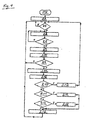
- einen Ablaufplan für eine Grobeinstellung der Dosiermenge des Vorbehandlungsmittels,
- Fig. 4:
- einen Ablaufplan für eine Feineinstellung der Dosiermenge des Vorbehandlungsmittels und
- Fig. 5:
- einen Ablaufplan für die Festlegung einer Änderung der Dosiermenge des Vorbehandlungsmittels während der Feineinstellung.
- Die in
Fig. 1 dargestellte Filtervorrichtung weist eine Filtereinheit 2 auf, welche mit einem Filter 4 in Form eines Membranfilters ausgestaltet ist. Eingangsseitig mündet an der Filtereinheit 2 eine Leitung 6. Über diese Leitung 6 wird eine zu filternde Flüssigkeit zu der Filtereinheit 2 geleitet. Hierbei wird die zu filternde Flüssigkeit mittels einer Pumpe 8 zu der Filtereinheit 2 und dort durch den Filter 4 gefördert. Ausgangsseitig der Filtereinheit 2 schließt sich an diese eine Leitung 10 an. Über diese Leitung 10 gelangt die gefilterte Flüssigkeit, d. h. das bei der Filterung erzeugte Permeat, in einen Sammeltank 12. An dem Sammeltank 12 ist eine Ausgangsleitung 14 ausgebildet, über welche das erzeugte Permeat zu einem Endverbraucher bzw. zu seiner endgültigen Bestimmung geleitet wird. - Während des Filterprozesses setzen sich in der zu filternden Flüssigkeit enthaltene Feststoffe an der Eingangsseite des Filters 4 ab. Diese Ablagerungen verringern während des Filterprozesses kontinuierlich die Filterfähigkeit des Filters 4. Daher wird der Filter 4 in vorgegebenen Abständen durch eine Rückspülung von den Ablagerungen befreit. Zu diesem Zweck wird ein Teil des bei der Filterung erzeugten Permeats, welches in dem Sammeltank 12 gespeichert ist, über eine sowohl mit dem Sammeltank 12 als auch mit der Filtereinheit 2 verbundene Leitung 16 in die Filtereinheit 2 geleitet und dort durch den Filter 4 von dessen Ausgangsseite zu dessen Innenseite geleitet. Hierbei fördert eine in der Leitung 16 angeordnete Pumpe 18 das zur Rückspülung verwendete Permeat von dem Sammeltank 12 durch den Filter 4. Infolge der Rückspülung lösen sich die Ablagerungen an der Eingangsseite des Filters 4 von dem Filter 4 und werden zusammen mit dem zur Rückspülung verwendeten Permeat aus der Filtereinheit 2 über einen Auslass 20 aus der Filtereinheit 2 entfernt.
- Zur Verbesserung der Reinigung des Filters 4 bei dessen Rückspülung wird der zu filternden Flüssigkeit eingangsseitig der Filtereinheit 2 ein Vorbehandlungsmittel beigemengt. Hierzu dient eine Dosierpumpe 20, die ein Pumpenteil 22, einen Antrieb 24 für das Pumpenteil 22 sowie eine Steuerung 26 aufweist, deren Bedeutung im weiteren Verlauf noch ausführlich dargelegt wird. Über eine Leitung 28 ist die Dosierpumpe 20 anströmseitig der Pumpe 8 mit der Leitung 6 verbunden. Die Dosierpumpe 20 empfängt ein Leistungssignal von den Pumpen 8 und 18. Zu diesem Zweck ist die Pumpe 8 über eine Signalleitung 30 mit der Steuerung 26 der Dosierpumpe 20 verbunden, während die Pumpe 18 über eine Signalleitung 32 mit der Steuerung 26 der Dosierpumpe 20 verbunden ist. Darüber hinaus können die Signalleitungen 30 und 32 Informationen bezüglich des Durchflusses der Pumpen 8 und 18 zu der Steuerung 26 übermitteln, wobei diese Informationen von den Pumpen 8 und 18 oder von externen Durchflusssensoren bereitgestellt werden, die in
Fig. 1 nicht dargestellt sind. - Die Steuerung 26 der Dosierpumpe 20 ist vorrangig zur Steuerung bzw. zur Einstellung der von der Dosierpumpe 20 abgegebenen Menge an Vorbehandlungsmittel vorgesehen. Hierbei ist die Steuerung 26 derart ausgebildet, dass von ihr die nachfolgend beschriebenen Verfahrensschritte veranlasst werden.
- Zu Beginn eines Filterprozesses wird von der Steuerung 26 mittels eines zu diesem Zweck vorgesehenen Steuerungsprogramms eine Grobeinstellung A (
Fig. 2 ) der von der Dosierpumpe 20 abgegebenen Dosiermenge des Vorbehandlungsmittels veranlasst. Die Arbeitsweise in diesem Steuerprogramm zur Grobeinstellung A entspricht dem inFig. 3 dargestellten Ablaufplan und wird anhand derFig. 2 und 3 erläutert. - Das Steuerungsprogramm zur Grobeinstellung A beginnt bei einem Start ST1. In einem auf den Start ST1 folgenden Programmschritt S1 wird ein erster Betrag für die Dosiermenge DM in einem ersten Dosierschritt D1 festgelegt. Dieser Dosierschritt D1 umfasst, wie auch alle nachfolgenden Dosierschritte, M Filterzyklen, wobei die Filterzyklen jeweils mit einer Rückspülung des Filters 4 beginnen und unmittelbar vor der nächsten Rückspülung des Filters 4 enden. Wie aus
Fig. 2 deutlich wird, in welcher die Dosiermengen DM (rechte vertikale Achse) für die Dosierschritte als waagerechte Linien dargestellt sind, beträgt die Dosiermenge DM für den ersten Dosierschritt D1 Null. - Nach dem Programschritt S1 folgt eine Abfrage R1, in welcher geklärt wird, ob bereits eine Rückspülung des Filters 4 erfolgt ist. Ist das Ergebnis dieser Abfrage R1 N (nein), so wird die Abfrage R1 wiederholt. Bei einem Ergebnis Y (ja), wird ein Programmschritt S2 ausgeführt.
- In dem Programmschritt S2 wird kontinuierlich der relative Energieverbrauch während des Filterzyklus berechnet. Dieser ergibt sich durch Division eines Gesamtenergieverbrauchs pro Filterzyklus mit einem pro Filterzyklus erzeugten Netto-Permeatvolumen. Hierbei werden zur Ermittlung des Gesamtenergieverbrauchs der Energieverbrauch zur Filterung, also der Energieverbrauch der Pumpe 8, der Energieverbrauch zur Rückspülung, also der Energieverbrauch der Pumpe 18, der Energieverbrauch zur Dosierung des Vorbehandlungsmittels, also der Energieverbrauch der Dosierpumpe 20 und ein Energiewert, welcher ein Äquivalent zu dem Vorbehandlungsmittelverbrauch darstellt, miteinander addiert und dieser Gesamtenergieverbrauch durch das Netto-Permeatvolumen, welches die Differenz zwischen der absolut erzeugten Permeatmenge und der zur Rückspülung verwendeten Permeatmenge ist, dividiert. Diese Berechnung wird während des gesamten Filterzyklus kontinierlich durchgeführt, wobei in einer Abfrage R2 jeweils geprüft wird, ob das Ende des Filterzyklus erreicht ist. Ist das Ergebnis dieser Abfrage N (nein), wird der Programmschritt S2 erneut ausgeführt. Bei einem Ergebnis Y (ja) der Abfrage R2 erfolgt ein Programmschritt S3.
- In dem Programmschritt S3 werden die während des Filterzyklus kontinuierlich berechneten Werte für den relativen Energieverbrauch zu einem Endwert für den relativen Energieverbrauch zusammengeführt und dieser Endwert gespeichert. Auf den Programmschritt S3 folgt ein Programmschritt S4. In diesem Programmschritt S4 wird eine Zählvariable für den Filterzyklus um einen Wert von 1 hochgesetzt. Auf den Programmschritt S4 folgt eine Abfrage R3. In dieser Abfrage R3 wird geprüft, ob die in Programmschritt S4 hochgesetzte Zählervariable für den Filterzyklus mit der Gesamtanzahl M der Filterzyklen pro Dosierschritt übereinstimmt. Ist das Ergebnis dieser Abfrage N (nein), beginnt der vorab beschriebene Vorgang wieder bei der Abfrage R1. Ist das Ergebnis der Abfrage R3 Y (ja), wird der Programmschritt S5 durchgeführt.
- In dem Programmschritt S5 werden aus den gespeicherten Werten für den relativen Energieverbrauch der M Filterzyklen eine virtuelle Funktionskurve des relativen Energieverbrauchs und ein Steigungswert dieser Funktionskurve für den derzeitigen Dosierschritt ermittelt. Diese Steigungswerte, auf deren Grundlage die Dosiermenge DM des Vorbehandlungsmittels eingestellt wird.
- Auf den Programmschritt S5 folgt eine Abfrage R4. In der Abfrage R4 wird geprüft, ob der in Programmschritt S5 ermittelte Steigungswert bzw. die Prozessvariable einen Wert kleiner als Null aufweist. Bei einem Ergebnis Y (ja) dieser Abfrage R4 ist ein Programmende PE1 erreicht, welches bedeutet, dass die augenblickliche Dosiermenge DM eine optimale Dosiermenge des Vorbehandlungsmittels ist. Bei einem Ergebnis N (nein) der Abfrage R4 wird eine weitere Abfrage R5 vorgenommen.
- In der Abfrage R5 wird abgefragt, ob der in Programmschritt S5 ermittelte Steigungswert bzw. die Prozessvariable des derzeitigen Dosierschritts größer als der Steigungswert des vorangehenden Dosierschritts ist. Ist das Ergebnis dieser Abfrage R5 Y (ja) ist ein Programmende PE2 erreicht, welches bedeutet, dass die Dosiermenge des vorangehenden Dosierschritts die optimale Dosierung der Grobeinstellung ist. Dies ist in
Fig. 2 bei der Dosiermenge DM3 der Fall. Ist das Ergebnis der Abfrage R5 N (nein), wird ein Programmschritt S6 durchgeführt. - In dem Programmschritt S6 wird die Dosiermenge DM des Vorbehandlungsmittels um einen feststehenden Betrag erhöht. Anschließend wird eine Abfrage R6 durchgeführt, in welcher geprüft wird, ob die Dosiermenge nach dem Programmschritt S6 einen maximal zulässigen Wert für die Dosiermenge DM überschreitet. Bei einem Ergebnis Y (ja) dieser Abfrage R6 ist auch das Programmende PE2 erreicht, was bedeutet, dass die Dosiermenge des vorangehenden Dosierschritts die maximale Dosierung der Grobeinstellung ist. Ist das Ergebnis der Abfrage R6 N (nein), beginnt der Prorammablauf aufs Neue mit der Abfrage R1.
- Wenn bei der Grobeinstellung A der Dosierung des Vorbehandlungsmittels eines der Programmenden PE1 oder PE2 erreicht worden ist, wird in der Steuerung 26 ein Programm zur Feineinstellung B der Dosiermenge des Vorbehandlungsmittels aufgerufen, das nachfolgend anhand der
Fig. 2 und4 erläutert wird. - Das Steuerprogramm zur Feineinstellung B beginnt bei einem Start ST2. In einem auf den Start ST2 folgenden Programmschritt S7 wird auf der Grundlage der Grobeinstellung A eine erste als näherungsweise optimal angesehene Dosiermenge DM5 (
Fig. 2 ) für einen ersten Dosierschritt D5 (Fig. 2 ) der Feineinstellung B eingestellt. - Auf den Programmschritt S7 folgt eine Abfrage R7. In der Abfrage R7 wird abgefragt, ob bereits eine Rückspülung des Filters 4 erfolgt ist. Ist das Ergebnis dieser Abfrage R7 N (nein), so wird die Abfrage R7 solange wiederholt, bis das Ergebnis der Abfrage R7 Y (ja) ist. Bei dem Ergebnis Y der Abfrage R7 wird der Programmschritt S8 ausgeführt.
- In dem Programmschritt S8 wird der relative Energieverbrauch während des Filterzyklus berechnet. Die Vorgehensweise ist hierbei identisch zu derjenigen bei dem Programmschritt S2 der Grobeinstellung A. Die Berechnung des relativen Energieverbrauchs erfolgt kontinuierlich während des gesamten Filterzyklus, wobei in einer Abfrage R8 nachgefragt wird, ob das Ende des Filterzyklus erreicht ist. Ist das Ergebnis dieser Abfrage R8 N (nein), so wird der Programmschritt S8 erneut ausgeführt. Bei einem Ergebnis Y (ja) der Abfrage R8 folgen auf die Abfrage R8 ein Programmschritt S9 und darauf ein Programmschritt S10.
- Die Programmschritte S9 und S10 sind identisch mit den Programmschritten S3 und S4 bei der Grobeinstellung A. So werden in Programmschritt S9 die während des Filterzyklus kontinuierlich berechneten Werte für den relativen Energieverbrauch zu einem Endwert zusammengeführt und dieser Endwert gespeichert, während in Programmschritt S10 eine Zählervariable für den Filterzyklus um einen Wert von 1 hochgesetzt wird.
- Auf den Programmschritt S10 folgt eine Abfrage R9, in welcher geprüft wird, ob die in Programmschritt S10 hochgesetzte Zählervariable für den Filterzyklus mit der Gesamtanzahl M der Filterzyklen pro Dosierschritt übereinstimmt. Bei einem Ergebnis N (nein) dieser Abfrage R9 beginnt der vorab beschriebene Vorgang wieder mit der Abfrage R7, auf welche der Programmschritt S8, die Abfrage R8, die Programmschritte S9 und S10 sowie die Abfrage R9 folgen. Ansonsten, d.h. bei einem Ergebnis Y (ja) der Abfrage R9, wird der Programmschritt S11 ausgeführt.
- Der Programmschritt S11 stimmt mit dem Programmschritt S5 bei der Grobeinstellung A überein. Demzufolge werden in dem Programmschritt S11 aus den gespeicherten Werten für den relativen Energieverbrauch der M Filterzyklen eine virtuelle Funktionskurve des relativen Energieverbrauchs ermittelt und ein Steigungswert DIR für den derzeitigen Dosierschritt ermittelt.
- In dem auf Programmschritt S11 folgenden Programmschritt S12 werden die Richtungen der in Programmschritt S11 ermittelten Steigungswerte (+ oder -) zu einem FIFO-Puffer (First IN-First OUT-Puffer) weitergeleitet und dort abgespeichert.
- Anschließend erfolgt eine Abfrage R10. In der Abfrage R10 wird abgefragt, ob der in Programmschritt S11 ermittelte Steigungswert DIR der virtuellen Funktionskurve des relativen Energieverbrauchs für den gegenwärtigen Dosierschritt kleiner als Null also negativ ist. Ist das Ergebnis der Abfrage R10 Y (ja), wird keine Änderung der Dosiermenge DM vorgenommen und der Programmschritt S13 ausgeführt.
- In dem Programmschritt S13 wird ein Zähler für den Dosierschritt um den Wert 1 hochgesetzt und die Feineinstellung B beginnt wieder bei der Abfrage R7 für den nächsten Dosierschritt, woraufhin der Programmschritt S8, die Abfrage R8, die Programmschritte S9 und S10, die Abfrage R9, die Programmschritte S11 und S12 sowie die Abfrage R10 folgen. Ist das Ergebnis der Abfrage R10 N (nein), erfolgt die Abfrage R11.
- In der Abfrage R11 wird abgefragt, ob der in Programmschritt S11 ermittelte Steigungswert DIR der virtuellen Funktionskurve des relativen Energieverbrauchs für den vorangehenden Dosierschritt kleiner als Null also negativ gewesen ist. Bei einem Ergebnis Y (ja) dieser Abfrage R11 wird der Programmschritt S14 ausgeführt, in dem der Wert für den Steigungswert DIR auf einen Wert von - 1 gesetzt wird, also DIR = -1. Anschließend wird der Programmschritt S16 ausgeführt.
- In dem Programmschritt S16 wird eine neue Dosiermenge DM für den nächsten Dosierschritt festgelegt und der Zähler für den Dosierschritt um den Wert 1 heraufgesetzt. Daraufhin beginnt die Feineinstellung B für diesen nächsten Dosierschritt wieder bei der Abfrage R7. Die Festlegung der Dosiermenge DM in Programmschritt S16 ergibt sich hierbei aus der Summe der gegenwärtigen Dosiermenge DM und dem Produkt aus dem Steigungswert DIR und aus einem Dosiermengenänderungswert DMA, welcher in einem in Verbindung mit dem FIFO-Puffer verwendeten Programm ermittelt wird. Hierauf wird nachfolgend noch eingehender eingegangen. Nach der Ausführung des Programmschritts S16 beginnt die Feineinstellung B für den nächsten Dosierschritt wieder bei der Abfrage R7.
- Bei einem Ergebnis N (nein) der Abfrage R11 folgt eine Abfrage R 12, in welcher abgefragt wird, ob der in Programmschritt S11 ermittelte Steigungswert DIR der virtuellen Funktionskurve des gespeicherten relativen Energieverbrauchs für den gegenwärtigen Dosierschritt größer als der Steigungswert DIR des vorangehenden Dosierschritts ist. Ist das Ergebnis dieser Abfrage Y (ja), wird der Programmschritt S15 durchgeführt, in dem das Vorzeichen des Steigungswerts DIR umgekehrt wird also DIR = DIR * (-1). Darauf folgend wird der Programmschritt S16 durchgeführt. Bei einem Ergebnis N (nein) der Abfrage R12 wird direkt der Programmschritt S16 durchgeführt.
- Der Programmablauf zur Ermittlung des Dosiermengenänderungswerts DMA geht aus
Fig. 5 hervor. Das Programm beginnt bei einem Start ST3. Dem Start ST3 folgt ein Programmschritt S17. In dem Programmschritt 17 wird ein drei Elemente umfassender FIFO-Puffer geschaffen. Auf den Programmschritt S17 erfolgt ein Programmschritt S18, in welchem die Grenzen festgelegt werden, innerhalb derer die Dosiermenge DM geändert werden kann, d.h., es werden eine Dosiermenge DMmin und eine Dosiermenge DMmax festgelegt. In einem auf den Dosierschritt S18 folgenden Programmschritt S19 wird ein Dosiermengenänderungsfaktor DMF festgelegt. Erfindungsgemäß bevorzugt ist der Dosiermengenänderungsfaktor DMF = 2. - In einer nachfolgenden Abfrage R13 wird abgefragt, ob die Dosiermenge DM der letzten drei Dosierschritte die in Programmschritt S18 festgelegten Grenzen der Dosiermenge erreicht hat. Bei einem Ergebnis Y (ja) der Abfrage R13, wird die Dosiermenge DM in einem Programmschritt S20 auf den Wert DMmin gesetzt. Anschließend wird eine Abfrage R14 durchgeführt.
- In der Abfrage R14 wird auf den im Programmschritt S11 der Feineinstellung B ermittelten Steigungswert DIR zurückgegriffen und abgefragt, ob der Steigungswert DIR negativ ist. Diese Abfrage R14 wird auch unmittelbar nach der Abfrage R13 vorgenommen, wenn das Ergebnis der Abfrage R13 N (nein) ist, d.h. wenn die Dosiermenge DM der letzten drei Dosierschritte die in Programmschritt S18 festgelegten Grenzen der Dosiermenge DM nicht erreicht hat. Bei einem Ergebnis Y (ja) der Abfrage R14 wird wieder zu der Abfrage R13 zurückgegangen, ansonsten, d.h. bei einem Ergebnis N (nein) der Abfrage R14 wird der Programmschritt S21 ausgeführt, in welchem die Tendenz der Steigungswerte DIR (0 für einen abnehmenden Steigungswert und 1 für einen ansteigenden Steigungswert) in dem FIFO-Puffer abgelegt werden.
- Dem Programmschritt S21 folgt eine Abfrage R15, in welcher abgefragt wird, ob der FIFO-Puffer voll ist, also drei Werte enthält. Ist das Ergebnis der Abfrage R15 N (nein), wird das Programm erneut mit der Anfrage R13 aufgenommen. Bei einem Ergebnis Y (ja) der Abfrage R15 folgt ein Programmschritt S22.
- In dem Programmschritt S22 wird gezählt, wie häufig sich die Tendenz der in dem FIFO-Puffer abgelegten drei Steigungswerte DIR (0 für einen abnehmenden Steigungswert und 1 für einen ansteigenden Steigungswert) geändert hat.
- Auf den Programmschritt S22 folgt eine Abfrage R16, in welcher abgefragt wird, ob sich die Tendenz des Steigungswerts DIR keinmal (Ergebnis 0), einmal (Ergebnis 1) oder zweimal (Ergebnis 2) geändert hat. Ist das Ergebnis der Abfrage R16 0, so wird der Programmschritt S23 ausgeführt, während bei einem Ergebnis 1 der Abfrage R16 der Programmschritt S24 und bei einem Ergebnis 2 der Abfrage R16 der Programmschritt S25 durchgeführt werden.
- In den Programmschritt S23, S24 und S25 wird der im Programmschritt S16 der Feineinstellung B verwendete Dosiermengenänderungswert DMA ermittelt. Hierbei ergibt sich der Dosiermengenänderungswert DMA bei dem Programmschritt S23 durch Multiplikation der vorangehenden Dosiermenge DM mit dem Dosiermengenänderungsfaktor DMF. Bei dem Programmschritt wird der Dosiermengenänderungswert DMA beibehalten und bei dem Programmschritt S25 ergibt sich der Dosiermengenänderungswert DMA durch Division der vorangehenden Dosiermenge DM durch den Dosiermengenänderungsfaktor DMF. In Programmschritt S26 wird das Programm zur Ermittlung des Dosiermengenänderungswerts DMA beendet.
- Aus der
Fig. 2 wird deutlich, dass dann, wenn sich bei der Feineinstellung die Größe der Prozessvariablen in großem Maße ändert (siehe Prozessvariablen PV19, PV20, PV21 inFig. 2 ), die Feineinstellung B der Dosiermenge DM abgebrochen wird und erneut eine Grobeinstellung A der Dosiermenge DM, wie anhand der Beschreibung vonFig. 3 beschrieben, durchgeführt wird. -
- 2
- Filtereinheit
- 4
- Filter
- 6
- Leitung
- 8
- Pumpe
- 10
- Leitung
- 12
- Sammeltank
- 14
- Ausgangsleitung
- 16
- Leitung
- 18
- Pumpe
- 20
- Dosierpumpe
- 22
- Pumpenteil
- 24
- Antrieb
- 26
- Steuerung
- 28
- Leitung
- 30
- Signalleitung
- 32
- Signalleitung
- A
- Grobeinstellung
- B
- Feineinstellung
- D1
- erster Dosierschritt
- DIR
- Steigungswert
- DM
- Dosiermenge
- DMA
- Dosiermengenänderungswert
- DMF
- Dosiermengenänderungsfaktor
- DMmax
- Maximale Dosiermenge
- DMmin
- Minimale Dosiermenge
- DM3
- Dosiermenge
- DM5
- Dosiermenge
- M
- Anzahl der Filterzyklen pro Dosierschritt
- N
- Ergebnis
- PE1
- Programmende
- PE2
- Programmende
- PV1
- Prozessvariable für den ersten Dosierschritt
- R1
- Abfrage
- R2
- Abfrage
- R3
- Abfrage
- R4
- Abfrage
- R5
- Abfrage
- R6
- Abfrage
- R7
- Abfrage
- R8
- Abfrage
- R9
- Abfrage
- R10
- Abfrage
- R11
- Abfrage
- R12
- Abfrage
- R13
- Abfrage
- R14
- Abfrage
- R15
- Abfrage
- R16
- Abfrage
- S1
- Programmschritt
- S2
- Programmschritt
- S3
- Programmschritt
- S4
- Programmschritt
- S5
- Programmschritt
- S6
- Programmschritt
- S7
- Programmschritt
- S8
- Programmschritt
- S9
- Programmschritt
- S10
- Programmschritt
- S11
- Programmschritt
- S12
- Programmschritt
- S13
- Programmschritt
- S14
- Programmschritt
- S15
- Programmschritt
- S16
- Programmschritt
- S17
- Programmschritt
- S18
- Programmschritt
- S19
- Programmschritt
- S20
- Programmschritt
- S21
- Programmschritt
- S22
- Programmschritt
- S23
- Programmschritt
- S24
- Programmschritt
- S25
- Programmschritt
- ST1
- Start
- ST2
- Start
- ST3
- Start
- Y
- Ergebnis
Claims (18)
- Filterverfahren, bei welchem eine zu filternde Flüssigkeit durch einen Filter (4) geleitet wird, der Filter (4) in vorgegebenen Abständen rückgespült wird und der Flüssigkeit eingangsseitig des Filters (4) ein Vorbehandlungsmittel beigefügt wird, dadurch gekennzeichnet, dass während der Filterung kontinuierlich eine die Effizienz der Filterung beschreibende Prozessvariable berechnet wird und eine Dosiermenge (DM) des Vorbehandlungsmittels auf der Grundlage der Werte für die Prozessvariable oder eines hiervon abgeleiteten Kennwerts in vorgegebenen Abständen angepasst wird.
- Filterverfahren nach Anspruch 1, dadurch gekennzeichnet, dass der Filterprozess in mehrere aufeinander folgende, jeweils mit einer Rückspülung des Filters (4) beginnende und vor Beginn der nächsten Rückspülung endende Filterzyklen aufgeteilt wird, wobei eine zu speichernde Prozessvariable für jeden Filterzyklus an einem vorgegebenen Zeitpunkt des Filterzyklus gespeichert wird.
- Filterverfahren nach Anspruch 2, dadurch gekennzeichnet, dass die Dosiermenge (DM) in Dosierschritten, welche jeweils eine bestimmte Anzahl von Filterzyklen umfassen, angepasst wird.
- Filterverfahren nach einem der vorangehenden Ansprüche, dadurch gekennzeichnet, dass die Prozessvariable ein relativer Energieverbrauch pro Filterzyklus ist, welcher durch Division eines Gesamtenergieverbrauchs pro Filterzyklus mit einem pro Filterzyklus erzeugten Netto-Permeatvolumen berechnet wird.
- Filterverfahren nach Anspruch 4, dadurch gekennzeichnet, dass der Gesamtenergieverbrauch pro Filterzyklus die Summe der pro Filterzyklus für die Filterung, die Rückspülung und die Dosierung des Vorbehandlungsmittels erforderliche Energie sowie eines ein Äquivalent zu dem Vorbehandlungsmittelverbrauch darstellenden Energiewerts ist.
- Filterverfahren nach einem der Ansprüche 4 oder 5, dadurch gekennzeichnet, dass das pro Filterzyklus erzeugte Netto-Permeatvolumen das pro Filterzylus erzeugte Permeatvolumen abzüglich eines pro Filterzyklus zur Rückspülung des Filters (4) verwendeten Permeatvolumens ist.
- Filterverfahren nach einem der Ansprüche 4 bis 6, dadurch gekennzeichnet, dass die zu speichernde Prozessvariable am Ende des Filterzyklus gespeichert wird und aus zwei oder mehr gespeicherten Prozessvariablen eine Funktionskurve ermittelt wird, wobei ein Steigungswert (DIR) dieser Funktionskurve für jeden Dosierschritt ermittelt wird.
- Filterverfahren nach einem der vorangehenden Ansprüche, dadurch gekennzeichnet, dass in einer ersten Phase des Filterprozesses eine Grobeinstellung (A) der Dosiermenge (DM) vorgenommen wird und die Dosiermenge (DM) in einer zweiten Phase des Filterprozesses ausgehend von einem bei der Grobeinstellung (A) ermittelten Dosiermenge (DM) in einer Feineinstellung (B) optimiert wird.
- Filterverfahren nach Anspruch 8, dadurch gekennzeichnet, dass die Dosiermenge (DM) bei der Grobeinstellung (A) in aufeinander folgenden Dosierschritten solange um den gleichen Betrag erhöht wird, solange sich die gespeicherte Prozessvariable in eine gleiche Richtung zu einem einen optimalen Prozesszustand des Filterprozesses darstellenden Wert verändert, wobei die Grobeinstellung (A) dann beendet wird, wenn sich die gespeicherte Prozessvariable in entgegengesetzte Richtung von dem den optimalen Prozesszustand darstellenden Wert wegbewegt.
- Filterverfahren nach einem der Ansprüche 8 oder 9, dadurch gekennzeichnet, dass die Dosiermenge (DM) bei der Feineinstellung (B) der Dosierung in aufeinanderfolgenden Dosierschritten jeweils angepasst wird, wobei sie in Abhängigkeit von der Entwicklung des Steigungswerts (DIR) verändert oder beibehalten wird.
- Filterverfahren nach Anspruch 10, dadurch gekennzeichnet, dass die Dosiermenge (DM) bei den Dosierschritten der Feineinstellung (B) variabel geändert wird, wobei der Betrag, um welchen die Dosiermenge (DM) geändert wird, auf der Grundlage der Tendenz der Steigungswerte (DIR) in den direkt vorangehenden Dosierschritten festgelegt wird.
- Filterverfahren nach Anspruch 10, dadurch gekennzeichnet, dass die Dosiermenge (DM) bei einem negativen Wert der Prozessvariablen beibehalten wird.
- Filterverfahren nach einem der Ansprüche 8 bis 12, dadurch gekennzeichnet, dass die Feineinstellung (B) der Dosiermenge (DM) bei einer sprunghaften Änderung der Prozessvariablen beendet wird und eine erneute Grobeinstellung (A) der Dosiermenge (DM) vorgenommen wird.
- Filterverfahren nach einem der vorangehenden Ansprüche, dadurch gekennzeichnet, dass das Vorbehandlungsmittel der zu filternden Flüssigkeit mit einer Verzögerung nach einer Rückspülung des Filters (4) beigefügt wird.
- Filterverfahren nach einem der vorangehenden Ansprüche, dadurch gekennzeichnet, dass der Beginn und das Ende eines Filterzyklus durch Überwachung der kontinuierlich berechneten Prozessvariablen oder einer in der Filtervorrichtung gemessenen Prozessgröße ermittelt werden.
- Filterverfahren nach Anspruch 15, dadurch gekennzeichnet, dass ein Beginn des Filterzyklus ermittelt wird, wenn die kontinuierlich berechnete Prozessvariable oder die gemessene Prozessgröße rapide abnimmt und ein Ende des Filterzyklus ermittelt wird, wenn die kontinuierlich berechnete Prozessvariable oder die gemessene Prozessgröße rapide ansteigt.
- Filtervorrichtung zum Filtern einer Flüssigkeit, mit mindestens einem Filter (4), mit mindestens einer Pumpe (8) zum Fördern der Flüssigkeit zu und durch den Filter (4) und mit einer Dosierpumpe (20) zum Beimengen eines Vorbehandlungsmittels zu der Flüssigkeit anströmseitig des Filters (4), dadurch gekennzeichnet, dass die Filtervorrichtung eine Steuerung (26) zum Steuern der Dosierpumpe (20) aufweist, welche derart ausgebildet ist, dass sie während der Filterung kontinuierlich eine die Effizienz der Filterung beschreibende Prozessvariable berechnet und die Dosierpumpe (20) auf der Grundlage der Werte für die Prozessvariable oder eines hiervon abgeleiteten Kennwerts steuert.
- Filtervorrichtung nach Anspruch 17, dadurch gekennzeichnet, dass die Steuerung (26) integraler Bestandteil der Dosierpumpe (20) ist.
Priority Applications (4)
| Application Number | Priority Date | Filing Date | Title |
|---|---|---|---|
| EP15202983.1A EP3187247B1 (de) | 2015-12-29 | 2015-12-29 | Filterverfahren zum filtern einer flüssigkeit |
| SG10201610513UA SG10201610513UA (en) | 2015-12-29 | 2016-12-15 | A filtering method for filtering a fluid and to a filter device for filtering a fluid |
| US15/392,371 US10668415B2 (en) | 2015-12-29 | 2016-12-28 | Filter method for filtering a fluid and adjusting a pre-treatment agent based on a process variable |
| CN201611240751.6A CN106943798B (zh) | 2015-12-29 | 2016-12-29 | 用于过滤液体的过滤方法和用于过滤液体的过滤装置 |
Applications Claiming Priority (1)
| Application Number | Priority Date | Filing Date | Title |
|---|---|---|---|
| EP15202983.1A EP3187247B1 (de) | 2015-12-29 | 2015-12-29 | Filterverfahren zum filtern einer flüssigkeit |
Publications (2)
| Publication Number | Publication Date |
|---|---|
| EP3187247A1 true EP3187247A1 (de) | 2017-07-05 |
| EP3187247B1 EP3187247B1 (de) | 2020-08-05 |
Family
ID=55077368
Family Applications (1)
| Application Number | Title | Priority Date | Filing Date |
|---|---|---|---|
| EP15202983.1A Active EP3187247B1 (de) | 2015-12-29 | 2015-12-29 | Filterverfahren zum filtern einer flüssigkeit |
Country Status (4)
| Country | Link |
|---|---|
| US (1) | US10668415B2 (de) |
| EP (1) | EP3187247B1 (de) |
| CN (1) | CN106943798B (de) |
| SG (1) | SG10201610513UA (de) |
Citations (4)
| Publication number | Priority date | Publication date | Assignee | Title |
|---|---|---|---|---|
| US20080314833A1 (en) * | 2007-06-22 | 2008-12-25 | Mosqueda-Jimenez Daniella Bere | Coagulant dosing process for membrane filtration |
| US20090308745A1 (en) * | 2007-10-23 | 2009-12-17 | Mcleod Gregg A | Process for enhanced total organic carbon removal while maintaining optimum membrane filter performance |
| US20100032373A1 (en) * | 2006-12-19 | 2010-02-11 | Degremont | Method for the optimised management of a membrane filtration unit and equipment for realising the same |
| US20130056412A1 (en) * | 2010-05-05 | 2013-03-07 | Sheng Chang | Mixed liquor filterability treatment in a membrane bioreactor |
Family Cites Families (3)
| Publication number | Priority date | Publication date | Assignee | Title |
|---|---|---|---|---|
| JP4094584B2 (ja) | 2004-07-07 | 2008-06-04 | 株式会社日立製作所 | 膜ろ過処理装置の運転支援装置 |
| FR2922466B1 (fr) * | 2007-10-19 | 2010-06-25 | Degremont | Procede de gestion avancee d'une unite de filtration sur membrane, et installation pour la mise en oeuvre du procede |
| KR100949658B1 (ko) | 2009-07-29 | 2010-03-26 | 주식회사 코오롱 | 여과막을 이용한 유체 처리 장치 |
-
2015
- 2015-12-29 EP EP15202983.1A patent/EP3187247B1/de active Active
-
2016
- 2016-12-15 SG SG10201610513UA patent/SG10201610513UA/en unknown
- 2016-12-28 US US15/392,371 patent/US10668415B2/en not_active Expired - Fee Related
- 2016-12-29 CN CN201611240751.6A patent/CN106943798B/zh not_active Expired - Fee Related
Patent Citations (4)
| Publication number | Priority date | Publication date | Assignee | Title |
|---|---|---|---|---|
| US20100032373A1 (en) * | 2006-12-19 | 2010-02-11 | Degremont | Method for the optimised management of a membrane filtration unit and equipment for realising the same |
| US20080314833A1 (en) * | 2007-06-22 | 2008-12-25 | Mosqueda-Jimenez Daniella Bere | Coagulant dosing process for membrane filtration |
| US20090308745A1 (en) * | 2007-10-23 | 2009-12-17 | Mcleod Gregg A | Process for enhanced total organic carbon removal while maintaining optimum membrane filter performance |
| US20130056412A1 (en) * | 2010-05-05 | 2013-03-07 | Sheng Chang | Mixed liquor filterability treatment in a membrane bioreactor |
Also Published As
| Publication number | Publication date |
|---|---|
| US20170182439A1 (en) | 2017-06-29 |
| CN106943798A (zh) | 2017-07-14 |
| CN106943798B (zh) | 2020-08-14 |
| SG10201610513UA (en) | 2017-07-28 |
| EP3187247B1 (de) | 2020-08-05 |
| US10668415B2 (en) | 2020-06-02 |
Similar Documents
| Publication | Publication Date | Title |
|---|---|---|
| EP0013334A2 (de) | Vorrichtung zur Infusion von Lösungen aus mehreren Infusionsflaschen | |
| EP0355632B1 (de) | Verfahren zum Aufbereiten der Bearbeitungsflüssigkeit einer Elektroerosionsmaschine | |
| DE102013113641A1 (de) | Vorrichtung und Verfahren zur Wasseraufbereitung | |
| EP2626120B1 (de) | Verfahren zur Steuerung und/oder Regelung eines Reinigungsprozesses eines Medienfilters | |
| DE3023463A1 (de) | Verfahren zur regelung von umwaelzpumpen fuer filteranlagen | |
| DE202016103007U1 (de) | Ölkreislauf mit Filtern insbesondere für Schiffsmotoren | |
| EP0085878B1 (de) | Verfahren zum Regeln eines kontinuierlich arbeitenden Druckfilters | |
| DE2730404A1 (de) | Verfahren zur steuerung der einem anschwemmfilter waehrend des filtrierbetriebes pro zeiteinheit zugefuehrten filterhilfsstoffmenge und vorrichtung zur durchfuehrung des verfahrens | |
| EP2465553A1 (de) | Extrakorporale Blutbehandlungsvorrichtung | |
| DE3828238C2 (de) | ||
| EP3187247B1 (de) | Filterverfahren zum filtern einer flüssigkeit | |
| DE60123562T2 (de) | Verfahren und Einrichtung zur Steuerung einer Flüssigkeitspumpe | |
| DE19607740A1 (de) | Verfahren zur Steuerung von Filtrationsanlagen | |
| DE2805204C3 (de) | Verfahren und Vorrichtung zum Filtrieren von Schlamm o.dgl. Filtergut in einer Filterpresse | |
| DE19905817A1 (de) | Verfahren für die Aufbereitung und die Konditionierung von im Kreislauf gefahrenem Walzöl | |
| DE2457844C3 (de) | Steuervorrichtung für periodisch arbeitende Filter | |
| DE2244917A1 (de) | Verfahren und einrichtung zum beschicken einer filtervorrichtung | |
| DE10322404B4 (de) | Dosierpumpe und Verfahren zu deren Steuerung | |
| DE3700804A1 (de) | Verfahren zur konzentration von geloesten substanzen sowie anlage fuer die konzentration | |
| DE3022679C2 (de) | ||
| DE4110158A1 (de) | Reinigungsvorrichtung | |
| DE3237251A1 (de) | Verfahren zur steuerung des betriebs eines verdichters | |
| DE3116610A1 (de) | Verfahren zur steuerung eines filters | |
| DE19546387C2 (de) | Verfahren und Vorrichtung zur Druckfiltration | |
| DE2525445A1 (de) | Verfahren zum klaeren von bierausschlagwuerze und klaerstrecke fuer brauereianlagen zum durchfuehren des verfahrens |
Legal Events
| Date | Code | Title | Description |
|---|---|---|---|
| PUAI | Public reference made under article 153(3) epc to a published international application that has entered the european phase |
Free format text: ORIGINAL CODE: 0009012 |
|
| STAA | Information on the status of an ep patent application or granted ep patent |
Free format text: STATUS: THE APPLICATION HAS BEEN PUBLISHED |
|
| AK | Designated contracting states |
Kind code of ref document: A1 Designated state(s): AL AT BE BG CH CY CZ DE DK EE ES FI FR GB GR HR HU IE IS IT LI LT LU LV MC MK MT NL NO PL PT RO RS SE SI SK SM TR |
|
| AX | Request for extension of the european patent |
Extension state: BA ME |
|
| STAA | Information on the status of an ep patent application or granted ep patent |
Free format text: STATUS: REQUEST FOR EXAMINATION WAS MADE |
|
| 17P | Request for examination filed |
Effective date: 20171221 |
|
| RBV | Designated contracting states (corrected) |
Designated state(s): AL AT BE BG CH CY CZ DE DK EE ES FI FR GB GR HR HU IE IS IT LI LT LU LV MC MK MT NL NO PL PT RO RS SE SI SK SM TR |
|
| STAA | Information on the status of an ep patent application or granted ep patent |
Free format text: STATUS: EXAMINATION IS IN PROGRESS |
|
| 17Q | First examination report despatched |
Effective date: 20190708 |
|
| GRAP | Despatch of communication of intention to grant a patent |
Free format text: ORIGINAL CODE: EPIDOSNIGR1 |
|
| STAA | Information on the status of an ep patent application or granted ep patent |
Free format text: STATUS: GRANT OF PATENT IS INTENDED |
|
| INTG | Intention to grant announced |
Effective date: 20200226 |
|
| GRAS | Grant fee paid |
Free format text: ORIGINAL CODE: EPIDOSNIGR3 |
|
| GRAA | (expected) grant |
Free format text: ORIGINAL CODE: 0009210 |
|
| STAA | Information on the status of an ep patent application or granted ep patent |
Free format text: STATUS: THE PATENT HAS BEEN GRANTED |
|
| AK | Designated contracting states |
Kind code of ref document: B1 Designated state(s): AL AT BE BG CH CY CZ DE DK EE ES FI FR GB GR HR HU IE IS IT LI LT LU LV MC MK MT NL NO PL PT RO RS SE SI SK SM TR |
|
| REG | Reference to a national code |
Ref country code: GB Ref legal event code: FG4D Free format text: NOT ENGLISH |
|
| REG | Reference to a national code |
Ref country code: CH Ref legal event code: EP |
|
| REG | Reference to a national code |
Ref country code: AT Ref legal event code: REF Ref document number: 1297912 Country of ref document: AT Kind code of ref document: T Effective date: 20200815 |
|
| REG | Reference to a national code |
Ref country code: DE Ref legal event code: R096 Ref document number: 502015013164 Country of ref document: DE |
|
| REG | Reference to a national code |
Ref country code: IE Ref legal event code: FG4D Free format text: LANGUAGE OF EP DOCUMENT: GERMAN |
|
| REG | Reference to a national code |
Ref country code: NL Ref legal event code: FP |
|
| REG | Reference to a national code |
Ref country code: LT Ref legal event code: MG4D |
|
| PG25 | Lapsed in a contracting state [announced via postgrant information from national office to epo] |
Ref country code: NO Free format text: LAPSE BECAUSE OF FAILURE TO SUBMIT A TRANSLATION OF THE DESCRIPTION OR TO PAY THE FEE WITHIN THE PRESCRIBED TIME-LIMIT Effective date: 20201105 Ref country code: GR Free format text: LAPSE BECAUSE OF FAILURE TO SUBMIT A TRANSLATION OF THE DESCRIPTION OR TO PAY THE FEE WITHIN THE PRESCRIBED TIME-LIMIT Effective date: 20201106 Ref country code: BG Free format text: LAPSE BECAUSE OF FAILURE TO SUBMIT A TRANSLATION OF THE DESCRIPTION OR TO PAY THE FEE WITHIN THE PRESCRIBED TIME-LIMIT Effective date: 20201105 Ref country code: SE Free format text: LAPSE BECAUSE OF FAILURE TO SUBMIT A TRANSLATION OF THE DESCRIPTION OR TO PAY THE FEE WITHIN THE PRESCRIBED TIME-LIMIT Effective date: 20200805 Ref country code: ES Free format text: LAPSE BECAUSE OF FAILURE TO SUBMIT A TRANSLATION OF THE DESCRIPTION OR TO PAY THE FEE WITHIN THE PRESCRIBED TIME-LIMIT Effective date: 20200805 Ref country code: PT Free format text: LAPSE BECAUSE OF FAILURE TO SUBMIT A TRANSLATION OF THE DESCRIPTION OR TO PAY THE FEE WITHIN THE PRESCRIBED TIME-LIMIT Effective date: 20201207 Ref country code: LT Free format text: LAPSE BECAUSE OF FAILURE TO SUBMIT A TRANSLATION OF THE DESCRIPTION OR TO PAY THE FEE WITHIN THE PRESCRIBED TIME-LIMIT Effective date: 20200805 Ref country code: HR Free format text: LAPSE BECAUSE OF FAILURE TO SUBMIT A TRANSLATION OF THE DESCRIPTION OR TO PAY THE FEE WITHIN THE PRESCRIBED TIME-LIMIT Effective date: 20200805 Ref country code: FI Free format text: LAPSE BECAUSE OF FAILURE TO SUBMIT A TRANSLATION OF THE DESCRIPTION OR TO PAY THE FEE WITHIN THE PRESCRIBED TIME-LIMIT Effective date: 20200805 |
|
| PG25 | Lapsed in a contracting state [announced via postgrant information from national office to epo] |
Ref country code: IS Free format text: LAPSE BECAUSE OF FAILURE TO SUBMIT A TRANSLATION OF THE DESCRIPTION OR TO PAY THE FEE WITHIN THE PRESCRIBED TIME-LIMIT Effective date: 20201205 Ref country code: LV Free format text: LAPSE BECAUSE OF FAILURE TO SUBMIT A TRANSLATION OF THE DESCRIPTION OR TO PAY THE FEE WITHIN THE PRESCRIBED TIME-LIMIT Effective date: 20200805 Ref country code: RS Free format text: LAPSE BECAUSE OF FAILURE TO SUBMIT A TRANSLATION OF THE DESCRIPTION OR TO PAY THE FEE WITHIN THE PRESCRIBED TIME-LIMIT Effective date: 20200805 Ref country code: PL Free format text: LAPSE BECAUSE OF FAILURE TO SUBMIT A TRANSLATION OF THE DESCRIPTION OR TO PAY THE FEE WITHIN THE PRESCRIBED TIME-LIMIT Effective date: 20200805 |
|
| PG25 | Lapsed in a contracting state [announced via postgrant information from national office to epo] |
Ref country code: EE Free format text: LAPSE BECAUSE OF FAILURE TO SUBMIT A TRANSLATION OF THE DESCRIPTION OR TO PAY THE FEE WITHIN THE PRESCRIBED TIME-LIMIT Effective date: 20200805 Ref country code: RO Free format text: LAPSE BECAUSE OF FAILURE TO SUBMIT A TRANSLATION OF THE DESCRIPTION OR TO PAY THE FEE WITHIN THE PRESCRIBED TIME-LIMIT Effective date: 20200805 Ref country code: SM Free format text: LAPSE BECAUSE OF FAILURE TO SUBMIT A TRANSLATION OF THE DESCRIPTION OR TO PAY THE FEE WITHIN THE PRESCRIBED TIME-LIMIT Effective date: 20200805 Ref country code: CZ Free format text: LAPSE BECAUSE OF FAILURE TO SUBMIT A TRANSLATION OF THE DESCRIPTION OR TO PAY THE FEE WITHIN THE PRESCRIBED TIME-LIMIT Effective date: 20200805 Ref country code: DK Free format text: LAPSE BECAUSE OF FAILURE TO SUBMIT A TRANSLATION OF THE DESCRIPTION OR TO PAY THE FEE WITHIN THE PRESCRIBED TIME-LIMIT Effective date: 20200805 |
|
| REG | Reference to a national code |
Ref country code: DE Ref legal event code: R097 Ref document number: 502015013164 Country of ref document: DE |
|
| PG25 | Lapsed in a contracting state [announced via postgrant information from national office to epo] |
Ref country code: AL Free format text: LAPSE BECAUSE OF FAILURE TO SUBMIT A TRANSLATION OF THE DESCRIPTION OR TO PAY THE FEE WITHIN THE PRESCRIBED TIME-LIMIT Effective date: 20200805 |
|
| PLBE | No opposition filed within time limit |
Free format text: ORIGINAL CODE: 0009261 |
|
| STAA | Information on the status of an ep patent application or granted ep patent |
Free format text: STATUS: NO OPPOSITION FILED WITHIN TIME LIMIT |
|
| PG25 | Lapsed in a contracting state [announced via postgrant information from national office to epo] |
Ref country code: SK Free format text: LAPSE BECAUSE OF FAILURE TO SUBMIT A TRANSLATION OF THE DESCRIPTION OR TO PAY THE FEE WITHIN THE PRESCRIBED TIME-LIMIT Effective date: 20200805 |
|
| 26N | No opposition filed |
Effective date: 20210507 |
|
| REG | Reference to a national code |
Ref country code: CH Ref legal event code: PL |
|
| PG25 | Lapsed in a contracting state [announced via postgrant information from national office to epo] |
Ref country code: SI Free format text: LAPSE BECAUSE OF FAILURE TO SUBMIT A TRANSLATION OF THE DESCRIPTION OR TO PAY THE FEE WITHIN THE PRESCRIBED TIME-LIMIT Effective date: 20200805 Ref country code: MC Free format text: LAPSE BECAUSE OF FAILURE TO SUBMIT A TRANSLATION OF THE DESCRIPTION OR TO PAY THE FEE WITHIN THE PRESCRIBED TIME-LIMIT Effective date: 20200805 |
|
| REG | Reference to a national code |
Ref country code: BE Ref legal event code: MM Effective date: 20201231 |
|
| PG25 | Lapsed in a contracting state [announced via postgrant information from national office to epo] |
Ref country code: LU Free format text: LAPSE BECAUSE OF NON-PAYMENT OF DUE FEES Effective date: 20201229 Ref country code: IE Free format text: LAPSE BECAUSE OF NON-PAYMENT OF DUE FEES Effective date: 20201229 |
|
| PG25 | Lapsed in a contracting state [announced via postgrant information from national office to epo] |
Ref country code: LI Free format text: LAPSE BECAUSE OF NON-PAYMENT OF DUE FEES Effective date: 20201231 Ref country code: CH Free format text: LAPSE BECAUSE OF NON-PAYMENT OF DUE FEES Effective date: 20201231 |
|
| REG | Reference to a national code |
Ref country code: AT Ref legal event code: MM01 Ref document number: 1297912 Country of ref document: AT Kind code of ref document: T Effective date: 20201229 |
|
| PG25 | Lapsed in a contracting state [announced via postgrant information from national office to epo] |
Ref country code: AT Free format text: LAPSE BECAUSE OF NON-PAYMENT OF DUE FEES Effective date: 20201229 |
|
| PG25 | Lapsed in a contracting state [announced via postgrant information from national office to epo] |
Ref country code: TR Free format text: LAPSE BECAUSE OF FAILURE TO SUBMIT A TRANSLATION OF THE DESCRIPTION OR TO PAY THE FEE WITHIN THE PRESCRIBED TIME-LIMIT Effective date: 20200805 Ref country code: MT Free format text: LAPSE BECAUSE OF FAILURE TO SUBMIT A TRANSLATION OF THE DESCRIPTION OR TO PAY THE FEE WITHIN THE PRESCRIBED TIME-LIMIT Effective date: 20200805 Ref country code: CY Free format text: LAPSE BECAUSE OF FAILURE TO SUBMIT A TRANSLATION OF THE DESCRIPTION OR TO PAY THE FEE WITHIN THE PRESCRIBED TIME-LIMIT Effective date: 20200805 |
|
| PG25 | Lapsed in a contracting state [announced via postgrant information from national office to epo] |
Ref country code: MK Free format text: LAPSE BECAUSE OF FAILURE TO SUBMIT A TRANSLATION OF THE DESCRIPTION OR TO PAY THE FEE WITHIN THE PRESCRIBED TIME-LIMIT Effective date: 20200805 |
|
| PG25 | Lapsed in a contracting state [announced via postgrant information from national office to epo] |
Ref country code: BE Free format text: LAPSE BECAUSE OF NON-PAYMENT OF DUE FEES Effective date: 20201231 |
|
| REG | Reference to a national code |
Ref country code: DE Ref legal event code: R082 Ref document number: 502015013164 Country of ref document: DE |
|
| PGFP | Annual fee paid to national office [announced via postgrant information from national office to epo] |
Ref country code: NL Payment date: 20221222 Year of fee payment: 8 Ref country code: GB Payment date: 20221223 Year of fee payment: 8 Ref country code: FR Payment date: 20221222 Year of fee payment: 8 Ref country code: DE Payment date: 20221213 Year of fee payment: 8 |
|
| PGFP | Annual fee paid to national office [announced via postgrant information from national office to epo] |
Ref country code: IT Payment date: 20221228 Year of fee payment: 8 |
|
| REG | Reference to a national code |
Ref country code: DE Ref legal event code: R119 Ref document number: 502015013164 Country of ref document: DE |
|
| REG | Reference to a national code |
Ref country code: NL Ref legal event code: MM Effective date: 20240101 |
|
| GBPC | Gb: european patent ceased through non-payment of renewal fee |
Effective date: 20231229 |
|
| PG25 | Lapsed in a contracting state [announced via postgrant information from national office to epo] |
Ref country code: NL Free format text: LAPSE BECAUSE OF NON-PAYMENT OF DUE FEES Effective date: 20240101 |
|
| PG25 | Lapsed in a contracting state [announced via postgrant information from national office to epo] |
Ref country code: NL Free format text: LAPSE BECAUSE OF NON-PAYMENT OF DUE FEES Effective date: 20240101 |
|
| PG25 | Lapsed in a contracting state [announced via postgrant information from national office to epo] |
Ref country code: DE Free format text: LAPSE BECAUSE OF NON-PAYMENT OF DUE FEES Effective date: 20240702 |
|
| PG25 | Lapsed in a contracting state [announced via postgrant information from national office to epo] |
Ref country code: GB Free format text: LAPSE BECAUSE OF NON-PAYMENT OF DUE FEES Effective date: 20231229 |
|
| PG25 | Lapsed in a contracting state [announced via postgrant information from national office to epo] |
Ref country code: FR Free format text: LAPSE BECAUSE OF NON-PAYMENT OF DUE FEES Effective date: 20231231 |
|
| PG25 | Lapsed in a contracting state [announced via postgrant information from national office to epo] |
Ref country code: GB Free format text: LAPSE BECAUSE OF NON-PAYMENT OF DUE FEES Effective date: 20231229 Ref country code: FR Free format text: LAPSE BECAUSE OF NON-PAYMENT OF DUE FEES Effective date: 20231231 Ref country code: DE Free format text: LAPSE BECAUSE OF NON-PAYMENT OF DUE FEES Effective date: 20240702 |
|
| PG25 | Lapsed in a contracting state [announced via postgrant information from national office to epo] |
Ref country code: IT Free format text: LAPSE BECAUSE OF NON-PAYMENT OF DUE FEES Effective date: 20231229 |