EP3183999A1 - Funktionsleiste fuer ein moebel sowie moebel mit einer funktionsleiste - Google Patents
Funktionsleiste fuer ein moebel sowie moebel mit einer funktionsleiste Download PDFInfo
- Publication number
- EP3183999A1 EP3183999A1 EP16205462.1A EP16205462A EP3183999A1 EP 3183999 A1 EP3183999 A1 EP 3183999A1 EP 16205462 A EP16205462 A EP 16205462A EP 3183999 A1 EP3183999 A1 EP 3183999A1
- Authority
- EP
- European Patent Office
- Prior art keywords
- furniture
- toolbar
- hinge
- flap
- mounting
- Prior art date
- Legal status (The legal status is an assumption and is not a legal conclusion. Google has not performed a legal analysis and makes no representation as to the accuracy of the status listed.)
- Withdrawn
Links
Images

Classifications
-
- A—HUMAN NECESSITIES
- A47—FURNITURE; DOMESTIC ARTICLES OR APPLIANCES; COFFEE MILLS; SPICE MILLS; SUCTION CLEANERS IN GENERAL
- A47B—TABLES; DESKS; OFFICE FURNITURE; CABINETS; DRAWERS; GENERAL DETAILS OF FURNITURE
- A47B96/00—Details of cabinets, racks or shelf units not covered by a single one of groups A47B43/00 - A47B95/00; General details of furniture
- A47B96/20—Furniture panels or like furniture elements
-
- E—FIXED CONSTRUCTIONS
- E05—LOCKS; KEYS; WINDOW OR DOOR FITTINGS; SAFES
- E05F—DEVICES FOR MOVING WINGS INTO OPEN OR CLOSED POSITION; CHECKS FOR WINGS; WING FITTINGS NOT OTHERWISE PROVIDED FOR, CONCERNED WITH THE FUNCTIONING OF THE WING
- E05F15/00—Power-operated mechanisms for wings
- E05F15/60—Power-operated mechanisms for wings using electrical actuators
- E05F15/603—Power-operated mechanisms for wings using electrical actuators using rotary electromotors
- E05F15/611—Power-operated mechanisms for wings using electrical actuators using rotary electromotors for swinging wings
- E05F15/616—Power-operated mechanisms for wings using electrical actuators using rotary electromotors for swinging wings operated by push-pull mechanisms
-
- E—FIXED CONSTRUCTIONS
- E05—LOCKS; KEYS; WINDOW OR DOOR FITTINGS; SAFES
- E05D—HINGES OR SUSPENSION DEVICES FOR DOORS, WINDOWS OR WINGS
- E05D3/00—Hinges with pins
- E05D3/06—Hinges with pins with two or more pins
- E05D3/14—Hinges with pins with two or more pins with four parallel pins and two arms
- E05D3/142—Hinges with pins with two or more pins with four parallel pins and two arms with at least one of the hinge parts having a cup-shaped fixing part, e.g. for attachment to cabinets or furniture
-
- E—FIXED CONSTRUCTIONS
- E05—LOCKS; KEYS; WINDOW OR DOOR FITTINGS; SAFES
- E05Y—INDEXING SCHEME ASSOCIATED WITH SUBCLASSES E05D AND E05F, RELATING TO CONSTRUCTION ELEMENTS, ELECTRIC CONTROL, POWER SUPPLY, POWER SIGNAL OR TRANSMISSION, USER INTERFACES, MOUNTING OR COUPLING, DETAILS, ACCESSORIES, AUXILIARY OPERATIONS NOT OTHERWISE PROVIDED FOR, APPLICATION THEREOF
- E05Y2201/00—Constructional elements; Accessories therefor
- E05Y2201/60—Suspension or transmission members; Accessories therefor
- E05Y2201/606—Accessories therefor
- E05Y2201/62—Synchronisation of suspension or transmission members
-
- E—FIXED CONSTRUCTIONS
- E05—LOCKS; KEYS; WINDOW OR DOOR FITTINGS; SAFES
- E05Y—INDEXING SCHEME ASSOCIATED WITH SUBCLASSES E05D AND E05F, RELATING TO CONSTRUCTION ELEMENTS, ELECTRIC CONTROL, POWER SUPPLY, POWER SIGNAL OR TRANSMISSION, USER INTERFACES, MOUNTING OR COUPLING, DETAILS, ACCESSORIES, AUXILIARY OPERATIONS NOT OTHERWISE PROVIDED FOR, APPLICATION THEREOF
- E05Y2201/00—Constructional elements; Accessories therefor
- E05Y2201/60—Suspension or transmission members; Accessories therefor
- E05Y2201/622—Suspension or transmission members elements
- E05Y2201/686—Rods, links
-
- E—FIXED CONSTRUCTIONS
- E05—LOCKS; KEYS; WINDOW OR DOOR FITTINGS; SAFES
- E05Y—INDEXING SCHEME ASSOCIATED WITH SUBCLASSES E05D AND E05F, RELATING TO CONSTRUCTION ELEMENTS, ELECTRIC CONTROL, POWER SUPPLY, POWER SIGNAL OR TRANSMISSION, USER INTERFACES, MOUNTING OR COUPLING, DETAILS, ACCESSORIES, AUXILIARY OPERATIONS NOT OTHERWISE PROVIDED FOR, APPLICATION THEREOF
- E05Y2900/00—Application of doors, windows, wings or fittings thereof
- E05Y2900/20—Application of doors, windows, wings or fittings thereof for furniture, e.g. cabinets
Definitions
- the invention relates to a toolbar for a furniture and a piece of furniture with such a toolbar.
- hinges of any kind are regularly mounted for pivoting a movable furniture part on a furniture body regularly on the furniture body on the one hand and on movable furniture parts on the other.
- the invention is based on the object to improve the reliability of a connection of a movable furniture part to a furniture body.
- the invention relates to a toolbar for a furniture for attachment to a furniture body or on a furniture body movable to the furniture part, which extends along the furniture part or the movable furniture part in the assembled state, said function bar mounting positions for attaching a hinge and at least a portion of a drive unit for includes a movement of the movable furniture part.
- the hinge may be a four-bar hinge, a single-axis hinge or a flap fitting fixedly mounted between a furniture body and a movable furniture part.
- the toolbar in a furniture body or the movable furniture part different, especially much more stable material, for example made of aluminum or a high-strength plastic or a composite material, which opens up the possibility of using the toolbar in comparison to conventional furniture materials To realize a significantly increased force application.
- mounting locations for a hinge or multiple hinges for guided movement of the movable furniture part can already be provided on the furniture body.
- the toolbar has first mounting means for a hinge.
- the first mounting means may, for example, comprise a recess into which a hinge cup of a hinge may be inserted.
- the function strip has second mounting means for attaching force introduction means of a drive unit.
- a force introduction means for example a force transmission element for, for example, a rotary shaft and / or a displacement element of a drive unit.
- the force introduction means may be a bearing block in which, for example, the end of a rotary shaft, possibly a propeller shaft is anchored, so that rotation of the rotary shaft entrains the bearing block and thus, for example.
- the movable furniture part is pivoted, in particular, in addition, the movable furniture part is hinged to hinges on the furniture body.
- the toolbar is designed for integration in a furniture carcass of a cabinet.
- the toolbar preferably forms a wall portion of the furniture part, for example, in the top floor of a cabinet body.
- the toolbar can be inserted in particular flush in a wall portion of the furniture and optionally extends over the entire width of, for example, an upper floor in a predetermined depth of for example 4 cm to 10 cm at a thickness in the range of several millimeters.
- the toolbar is designed for integration in a furniture door or furniture flap.
- the function bar can be attached to the movable furniture part.
- the toolbar may have as for the furniture body corresponding dimensions, that is, run over the entire width of the furniture flap or furniture door. It is preferred if the toolbar is flush with surface portions of the remaining movable furniture part is used.
- the functional strip can be screwed, glued, clipped in or fastened with other anchoring means for anchoring in the furniture.
- the toolbar has a mounting location for a damper.
- a damping element can be mounted on the toolbar at a predetermined mounting position, which allows a damped movement especially when closing.
- holes, tapped holes, etc. may be provided, possibly also at different positions of the toolbar, so that alternative mounting options on the toolbar.
- the function strip for mounting a hinge, a drive part or a damper can prepare several alternative positions prepared.
- the function bar comprises a mounting space for an electric drive.
- the toolbar is equipped with a hinge and at least part of a drive unit.
- the part of the drive unit may comprise, for example, force introduction means and a rotary shaft.
- the rest of the drive unit can be arranged on another toolbar or the remaining furniture.
- a rotary element with universal joint of a drive unit can be mounted on the function strip, the force being able to be introduced onto the function strip via the end of the rotary element which can be set in motion via a rotary drive of the drive unit, for example via a corresponding force introduction element, such as, for example Bearing or clamping block.
- the drive unit for example, a rotary drive is arranged on the toolbar or on another toolbar and a power transmission via power transmission means, optionally the hinge takes place on the other furniture part.
- a linear drive which is constructed according to a drill bit principle according to a ball screw to convert a linear motion into a rotary motion, which is then used for moving, in particular pivoting the movable furniture part.
- the rotary spindle is driven by a rotary drive, wherein the nut on the spindle provides the force for the movement of the movable furniture part in the form of a linear movement, with which, for example, the hinge is driven.
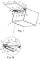
- FIG. 1 is a top cabinet 1 comprising a cabinet body 2 and a flap 3 is shown, which is articulated via two hinges 4, 5, for example, four-bar hinges on the cabinet body 2.
- FIG. 1a shows a hinge arm 5a and a hinge lever 5b of the four-joint of the hinge 5 is increased.
- the flap 3 can be opened and closed on the cabinet body 2 via a shaft drive 6.
- the cardan drive 6 comprises a cardan shaft 7 with two universal joints 7 a and 7 b with an intermediate rotary shaft 7 c and a gear 8 and a motor. 9
- the universal joint 7a is fixed to the side facing away from the rotary shaft 7c on a mounting block 10, so that a movement of the universal joint shaft 7 directly has a movement of the mounting block 10 result.
- the universal joint 7b is connected to an output shaft of the transmission 8, which can be driven by the motor 9.
- cardan drive 6 is also another type of rotary drive conceivable, for example, via a flexible shaft or gear means, for example, act directly on at least one hinge.
- the hinge cups 4c and 5c sit in the flap 3 in one Function bar 11 in preferably prepared there receiving openings (not shown).
- Threaded holes are provided for mounting flanges laterally on the hinge cups 4c, 5c, for example, to secure the mounting flanges with screws in the toolbar 11 can.
- the functional strip 11 is preferably made of material remaining relatively stable flap, for example, as an aluminum strip or a composite material with comparatively high stability.
- this allows a secure attachment of the mounting block 10 with a force on the flap 3, which readily withstand the forces that are introduced via the shaft drive 6 on the flap 3.
- threaded holes are preferably also already provided in the toolbar 11 to secure the mounting block 10 securely on the toolbar 11 can.
- the function strip 11 extends, for example, over the entire width b of the flap 3 and a depth h, so that at least the hinge pots can be accommodated in the function strip 11.
- the thickness d of the toolbar is preferably such that it has a smaller dimension than the thickness of the flap 3, so that on the visible front, the toolbar is covered by the material of the remaining flap.
- the remaining flap preferably has a cross-sectionally L-shaped recess into which the functional strip 11 is inserted, advantageously such that the inner surfaces and the lateral end faces are aligned.
- the toolbar 11 can be connected by a variety of methods with the remaining flap, for example by screws, rivets, glue.
- the transmission 8 with motor 9 is at the top bottom 2a (see in particular FIG. 2 ) fixed. Likewise, the hinge arms 4 a, 5 a are fixed there.
- a functional strip is also arranged on the upper floor 2a, in order to be able to attach the hinge arms 4a, 5a of the hinges 4, 5 as well as the gear 8 with motor 9.
- hinges instead of the illustrated four-bar hinges other embodiments of hinges are possible. Likewise, instead of a shaft drive another type of drive can be used.
- FIG. 2 is a sectional view of the upper cabinet 1 in the open state of the flap 3 is shown.
- the cardan shaft 7 is pivoted out of the axis of a transmission shaft of the transmission 8 in order to follow the movement of the mounting block 10 on the toolbar 11 of the flap 3.
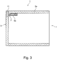
- FIG. 3 The closed state of the flap 3 is in FIG. 3 illustrated, also in a sectional view from the side.
- the cardan shaft 7 is pivoted back into its "closed” position.
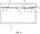
- FIG. 4 an alternative embodiment of an upper cabinet 1a with drive system 12 for moving the upper flap 3 on the furniture body 2 is illustrated.
- the upper cabinet 1 a has between the flap 3 and body 2 For example, the same hinges 4, 5, as the upper cabinet 1 according to the FIGS. 1 to 3 ,
- the drive system 12 is constructed as follows:
- a linear movement is provided, which is transmitted via a coupling piece 14 to a nut 15 which runs on a spindle 16, so that in a linear movement of the nut 15th the spindle 16 is rotated.
- the rotational movement of the spindle 16 may, for example, as in FIG. 4 represented by a gear 17 on a universal joint shaft 7 according to the embodiment according to the FIGS. 1 to 3 be transferred, wherein the hinge 5 facing the universal joint 7a is fixed to a mounting block 10a, which in turn, as the hinge cups of the hinges 4, 5 is fixed to a toolbar 18 which sits in the flap 3.
- a linear movement of the unit 13 via the nut 15 and the spindle 16 is converted into a rotational movement, optionally reduced to a desired speed with the gear 17, with which then the universal joint 7, the flap 3 on the furniture body 2 upon actuation of the unit 3 pivots.
- the unit 13 and the gear 17 and the hinge arms of the hinges 4, 5 are arranged on a toolbar, which sits on or in the upper bottom 2a of the cabinet body 2.
- the toolbar 11 and also other toolbars may be placed on the flap 3 or a surface of the cabinet body or partially or completely embedded.
Landscapes
- Hinges (AREA)
Abstract
Description
- Die Erfindung betrifft eine Funktionsleiste für ein Möbel sowie ein Möbel mit einer solchen Funktionsleiste.
- Bei bekannten Ausführungsformen werden Scharniere gleich jedweder Art regelmäßig zum Verschwenken eines beweglichen Möbelteils an einem Möbelkorpus regelmäßig am Möbelkorpus einerseits und an beweglichen Möbelteilen andererseits montiert.
- Der Erfindung liegt die Aufgabe zu Grunde, die Zuverlässigkeit einer Anbindung eines beweglichen Möbelteils an einem Möbelkorpus zu verbessern.
- Diese Aufgabe wird durch die Merkmale des Anspruchs 1 und 9 gelöst.
- In den anhängigen Ansprüchen sind vorteilhafte und zweckmäßige Weiterbildungen der Erfindung angegeben.
- Die Erfindung betrifft eine Funktionsleiste für ein Möbel zur Anbringung an einem Möbelkorpus oder an einem zum Möbelkorpus beweglichen Möbelteil, die sich entlang des Möbelteils oder des beweglichen Möbelteils im montierten Zustand erstreckt, wobei die Funktionsleiste Montageplätze zur Anbringung eines Scharniers sowie zumindest eines Teils einer Antriebseinheit für eine Bewegung des beweglichen Möbelteils umfasst.
- Grundsätzlich geht es um das Schwenken eines beweglichen Möbelteils zu einem Möbelkorpus bei ortsfest positioniertem Scharnier am Möbelkorpus einerseits und am beweglichen Möbelteil andererseits.
- Das Scharnier kann ein Viergelenk, ein Einachs-Scharnier oder ein Klappenbeschlag sein, der fest zwischen Möbelkorpus und einem beweglichen Möbelteil montiert ist.
- Durch die erfindungsgemäße Vorgehensweise kann beispielsweise die Funktionsleiste in einem zum Möbelkorpus oder dem beweglichen Möbelteil verschieden, insbesondere deutlich stabilerem Material, beispielsweise aus Aluminium oder einem hochfesten Kunststoff bzw. einem Verbundwerkstoff ausgebildet werden, was die Möglichkeit eröffnet, über die Funktionsleiste im Vergleich zu herkömmlichen Möbelmaterialien eine deutlich erhöhte Krafteinleitung zu realisieren. Zudem können bereits Montagestellen für ein Scharnier bzw. mehrere Scharniere zum geführten Bewegen des beweglichen Möbelteils am Möbelkorpus vorgesehen werden.
- Im Weiteren ist es bevorzugt, dass die Funktionsleiste erste Montagemittel für ein Scharnier aufweist. Die ersten Montagemittel können zum Beispiel eine Ausnehmung umfassen, in welche ein Scharniertopf eines Scharniers eingesetzt werden kann. Vorzugsweise sind darüber hinaus oder alternativ bereits Bohrungen, insbesondere Gewindebohrungen zum Befestigen des Scharniers, zum Beispiel über Montageflansche am Scharniertopf vorhanden.
- In einer überdies bevorzugten Ausführungsform besitzt die Funktionsleiste zweite Montagemittel zur Anbringung von Krafteinleitungsmittel einer Antriebseinheit.
- Beispielsweise sind Ausnehmungen, Gewindebohrungen und/oder Bohrungen vorgesehen, um ein Krafteinleitungsmittel, zum Beispiel ein Kraftübertragungselement für zum Beispiel eine Drehwelle und/oder ein Verschiebeelement einer Antriebseinheit anbringen zu können. Die Krafteinleitungsmittel können ein Lagerblock sein, in welchem zum Beispiel das Ende einer Drehwelle, gegebenenfalls einer Kardanwelle verankert ist, sodass eine Drehung der Drehwelle den Lagerblock mitnimmt und damit z.B. das bewegliche Möbelteil verschwenkt wird, wobei insbesondere zusätzlich das bewegliche Möbelteil an Scharnieren am Möbelkorpus angeschlagen ist.
- Überdies bevorzugt ist es, wenn die Funktionsleiste zur Integration in einem Möbelkorpus eines Schranks ausgestaltet ist. Die Funktionsleiste bildet vorzugsweise einen Wandabschnitt des Möbelteils, zum Beispiel im Oberboden eines Schrankkorpus. Die Funktionsleiste lässt sich insbesondere bündig in einen Wandabschnitt des Möbels einfügen und verläuft gegebenenfalls über die komplette Breite zum Beispiel eines Oberbodens in einer vorgegebenen Tiefe von beispielsweise 4 cm bis 10 cm bei einer Dicke im Bereich von mehreren Millimetern.
- Außerdem vorteilhaft ist es, wenn die Funktionsleiste zur Integration in einer Möbeltür oder Möbelklappe ausgebildet ist.
- Zusätzlich oder alternativ zu einer Anbringung im Möbelkorpus lässt sich die Funktionsleiste am beweglichen Möbelteil anbringen. Die Funktionsleiste kann dabei wie für den Möbelkorpus entsprechende Dimensionierungen aufweisen, das heißt, über die komplette Breite der Möbelklappe oder Möbeltür verlaufen. Es ist bevorzugt, wenn die Funktionsleiste bündig zu Flächenabschnitten des verbleibenden beweglichen Möbelteils eingesetzt ist.
- Die Funktionsleiste kann zur Verankerung im Möbel zum Beispiel eingeschraubt, eingeklebt, eingeclipst oder mit anderen Verankerungsmitteln ausgestattet sein.
- In einer weiterhin vorteilhaften Ausgestaltung der Erfindung weist die Funktionsleiste ein Montageplatz für einen Dämpfer auf.
- Um ein kontrolliertes Schließen eines beweglichen Möbelteils an einem Möbelkorpus zu gewährleisten, kann an der Funktionsleiste an einem vorgegebenen Montageplatz ein Dämpfelement montierbar sein, das insbesondere beim Schließen einen gedämpften Bewegungsablauf ermöglicht.
- Für die Verankerung des Dämpfelements können Ausnehmungen, Bohrungen, Gewindebohrungen, usw. vorgesehen sein, gegebenenfalls auch an verschiedenen Positionen der Funktionsleiste, sodass alternative Montagemöglichkeiten an der Funktionsleiste bestehen.
- Grundsätzlich kann die Funktionsleiste zur Anbringung von einem Scharnier, einem Antriebsteil oder einem Dämpfer mehrere alternative Positionen vorbereitet ermöglichen.
- Um einfach ein Bewegungssystem zur Bewegung eines beweglichen Möbelteils an einem Möbel integrieren zu können, wird über dies vorgeschlagen, dass die Funktionsleiste einen Montageplatz für einen elektrischen Antrieb umfasst.
- Vorzugsweise ist die Funktionsleiste mit einem Scharnier und mindestens einem Teil einer Antriebseinheit ausgestattet. Das Teil der Antriebseinheit kann zum Beispiel Krafteinleitungsmittel sowie eine Drehwelle umfassen. Die übrige Antriebseinheit kann an einer weiteren Funktionsleiste oder am verbleibenden Möbel angeordnet sein.
- An der Funktionsleiste kann ein Drehelement mit Kardangelenk einer Antriebseinheit gelagert sein, wobei über das Ende des Drehelements, das über einen Drehantrieb der Antriebseinheit in Bewegung setzbar ist, die Kraft auf die Funktionsleiste eingeleitet werden kann, beispielsweise über ein entsprechendes Krafteinleitungselement, wie zum Beispiel ein Lager- bzw. Klemmblock.
- Ebenso ist es denkbar, dass die Antriebseinheit, zum Beispiel ein Drehantrieb auf der Funktionsleiste bzw. auf einer anderen Funktionsleiste angeordnet ist und eine Kraftübertragung über Kraftübertragungsmittel, gegebenenfalls das Scharnier auf das andere Möbelteil stattfindet.
- Es sind verschiedene Antriebssysteme denkbar, zum Beispiel auch ein Linearantrieb, der nach einem Drillbohrerprinzip entsprechend einer Kugelumlaufspindel aufgebaut ist, um eine Linearbewegung in eine Drehbewegung umzuwandeln, die dann für das Bewegen, insbesondere Schwenken des beweglichen Möbelteils einsetzbar ist.
- Es ist jedoch auch ein entgegengesetztes Prinzip möglich, bei welchem die Drehspindel von einem Drehantrieb angetrieben wird, wobei die Mutter auf der Spindel die Kraft für die Bewegung des beweglichen Möbelteils in Form einer Linearbewegung bereitstellt, mit welcher zum Beispiel das Scharnier angetrieben wird.
- Zwei Ausführungsbeispiele der Erfindung sind in den Figuren unter Angabe weiterer Vorteile und Einzelheiten näher erläutert. Es zeigen
- Figur 1
- in einer perspektivischen Darstellung einen Oberschrank mit geöffneter Klappe und Kardanantrieb,
- Figur 1a:
- den Ausschnitt A aus
Figur 1 vergrößert dargestellt, - Figur 2:
- eine seitliche Schnittansicht des Oberschranks aus
Figur 1 , - Figur 3:
- eine seitliche Schnittansicht des Oberschranks gemäß
Figur 1 mit geschlossener Klappe und - Figur 4:
- eine weitere Ausführungsform eines Oberschranks mit geöffneter Oberklappe und Antriebseinheit zum Öffnen der Oberklappe in Frontansicht,
- In
Figur 1 ist ein Oberschrank 1 umfassend einen Schrankkorpus 2 sowie eine Klappe 3 dargestellt, die über zwei Scharniere 4, 5, zum Beispiel Viergelenkscharniere am Schrankkorpus 2 angelenkt ist. - In
Figur 1a zeigt einen Scharnierarm 5a sowie einen Gelenkhebel 5b des Viergelenks des Scharniers 5 vergrößert. Die Klappe 3 kann am Schrankkorpus 2 über einen Kardanantrieb 6 geöffnet und geschlossen werden. Der Kardanantrieb 6 umfasst eine Kardangelenkwelle 7 mit zwei Kardangelenken 7a und 7b mit einer dazwischenliegenden Drehwelle 7c sowie ein Getriebe 8 und ein Motor 9. - Das Kardangelenk 7a ist mit der zur Drehwelle 7c abgewandten Seite an einem Montageblock 10 fixiert, sodass eine Bewegung der Kardangelenkwelle 7 unmittelbar eine Bewegung des Montageblocks 10 zur Folge hat.
- Das Kardangelenk 7b ist mit einer Ausgangswelle des Getriebes 8 verbunden, das vom Motor 9 angetrieben werden kann.
- Anstelle eines Kardanantriebs 6 ist auch eine andere Art eines Drehantriebs denkbar zum Beispiel auch über eine biegsame Welle oder Getriebemittel, die beispielsweise unmittelbar auf zumindest ein Scharnier wirken.
- Die Scharniertöpfe 4c bzw. 5c sitzen in der Klappe 3 in einer Funktionsleiste 11 in vorzugsweise dort vorbereiteten Aufnahmeöffnungen (nicht dargestellt). In der Funktionsleiste 11 sind für Montageflansche seitlich an den Scharniertöpfen 4c, 5c zum Beispiel Gewindebohrungen vorgesehen, um die Montageflansche mit Schrauben in der Funktionsleiste 11 befestigen zu können.
- Die Funktionsleiste 11 ist vorzugsweise aus zu verbleibender Klappe vergleichsweise stabilerem Material ausgebildet, zum Beispiel als Aluminiumleiste oder aus einem Werkstoffverbund mit vergleichsweisen hoher Stabilität.
- Insbesondere dies ermöglicht ein sicheres Anbringen des Montageblocks 10 mit einer Krafteinleitung auf die Klappe 3, die den auftretenden Kräften, welche über den Kardanantrieb 6 auf die Klappe 3 eingeleitet werden, ohne Weiteres standhält.
- Für den Montageblock 10 sind vorzugsweise ebenfalls bereits Gewindebohrungen in der Funktionsleiste 11 vorgesehen, um den Montageblock 10 sicher an der Funktionsleiste 11 befestigen zu können.
- Die Funktionsleiste 11 verläuft zum Beispiel über die komplette Breite b der Klappe 3 und einer Tiefe h, sodass zumindest die Scharniertöpfe in der Funktionsleiste 11 Platz finden. Die Dicke d der Funktionsleiste ist vorzugsweise so bemessen, dass sie ein geringeres Maß hat, als die Dicke der Klappe 3, sodass an der sichtbaren Front die Funktionsleiste vom Material der verbleibenden Klappe überdeckt ist. Die verbleibende Klappe hat dazu vorzugsweise eine in Querschnitt L-Förmige Ausnehmung, in welche die Funktionsleiste 11 eingesetzt ist, vorteilhafter Weise so, dass die inneren Oberflächen als auch die seitlichen Stirnflächen fluchten.
- Die Funktionsleiste 11 kann mit verschiedensten Verfahren mit der verbleibenden Klappe verbunden sein, zum Beispiel durch Schrauben, Nieten, kleben.
- Das Getriebe 8 mit Motor 9 ist am Oberboden 2a (siehe insbesondere
Figur 2 ) fixiert. Ebenso sind die Scharnierarme 4 a, 5 a dort befestigt. - Denkbar ist, dass am Oberboden 2a ebenfalls eine Funktionsleiste angeordnet ist, um daran die Scharnierarme 4a, 5a der Scharniere 4, 5 als auch das Getriebe 8 mit Motor 9 anbringen zu können.
- Auf diese Weise ist es möglich, eine vollständige Bewegungseinheit aus Funktionsleisten, Scharnieren, Kardanantrieb sowie Getriebe und Motor als System vormontiert an Funktionsleisten an der gegebenenfalls vorbereiteten Klappe 3 bzw. dem gegebenenfalls vorbereiteten Korpus 3 anbringen zu können.
- An Stelle der dargestellten Viergelenkscharniere sind andere Ausführungsformen von Scharnieren möglich. Ebenso kann anstatt eines Kardanantriebs eine andere Art eines Antriebs eingesetzt werden.
- In
Figur 2 ist eine Schnittdarstellung des Oberschranks 1 in geöffnetem Zustand der Klappe 3 gezeigt. Hier ist ersichtlich, dass die Kardangelenkwelle 7 aus der Achse einer Getriebewelle des Getriebes 8 herausschwenkt ist, um der Bewegung des Montageblocks 10 an der Funktionsleiste 11 der Klappe 3 zu folgen. - Der geschlossene Zustand der Klappe 3 ist in
Figur 3 veranschaulicht, ebenfalls in einem Schnittbild von der Seite. Die Kardangelenkwelle 7 ist dabei in ihre "geschlossen"-Position zurückgeschwenkt. - In
Figur 4 ist eine alternative Ausgestaltung eines Oberschranks 1a mit Antriebssystem 12 für das Bewegen der Oberklappe 3 am Möbelkorpus 2 veranschaulicht. - Der Oberschrank 1 a weist zwischen Klappe 3 und Korpus 2 beispielsweise die gleichen Scharniere 4, 5 auf, wie der Oberschrank 1 entsprechend der
Figuren 1 bis 3 . - An einer Einheit 13, die zum Beispiel am Oberboden 2a des Schrankkorpus 3 montiert ist, wird zum Beispiel eine Linearbewegung bereitgestellt, die über ein Kopplungsstück 14 auf eine Mutter 15 übertragen wird, welche auf einer Spindel 16 läuft, sodass bei einer Linearbewegung der Mutter 15 die Spindel 16 in Drehung versetzt wird. Die Drehbewegung der Spindel 16 kann zum Beispiel wie in
Figur 4 dargestellt über ein Getriebe 17 auf eine Kardangelenkwelle 7 entsprechend der Ausführungsform gemäß derFiguren 1 bis 3 übertragen werden, wobei das zum Scharnier 5 weisende Kardangelenk 7a an einem Montageblock 10a fixiert ist, der seinerseits, so wie die Scharniertöpfe der Scharniere 4, 5 an einer Funktionsleiste 18, die in der Klappe 3 sitzt, fixiert ist. Somit wird eine Linearbewegung der Einheit 13 über die Mutter 15 und die Spindel 16 in eine Drehbewegung umgesetzt, mit dem Getriebe 17 gegebenenfalls auf eine gewünschte Drehzahl reduziert, mit welcher dann die Kardangelenkwelle 7 die Klappe 3 am Möbelkorpus 2 bei Betätigung der Einheit 3 schwenkt. - Auch hier ist es denkbar, dass die Einheit 13 sowie das Getriebe 17 als auch die Scharnierarme der Scharniere 4, 5 an einer Funktionsleiste angeordnet sind, die am oder im Oberboden 2a des Schrankkorpus 2 sitzt.
- Die Funktionsleiste 11 und auch weitere Funktionsleisten können auf die Klappe 3 bzw. eine Oberfläche des Schrankkorpus aufgesetzt sein oder teilweise bzw. ganz eingelassen sein.
- Um bestehende Möbel nachzurüsten, ist eine Variante denkbar, bei welcher insbesondere an der Klappe 3 eine Funktionsleiste auf die Innenseite der Klappe aufgesetzt wird.
-
- 1
- Oberschrank
- 1a
- Oberschrank
- 2
- Schrankkorpus
- 2a
- Oberboden
- 3
- Klappe
- 4
- Scharnier
- 4a
- Scharnierarm
- 4c
- Scharniertopf
- 5
- Scharnier
- 5a
- Scharnierarm
- 5b
- Gelenkarm
- 5c
- Scharniertopf
- 6
- Kardanantrieb
- 7
- Kardangelenkwelle
- 7a
- Kardangelenk
- 7b
- Kardangelenk
- 7c
- Drehwelle
- 8
- Getriebe
- 9
- Motor
- 10
- Montageblock
- 10a
- Montageblock
- 11
- Funktionsleiste
- 12
- Antriebssystem
- 13
- Einheit
- 14
- Kopplungsteil
- 15
- Mutter
- 16
- Spindel
- 17
- Getriebe
- 18
- Funktionsleiste
Claims (10)
- Funktionsleiste (11, 18) für ein Möbel (1, 1a) zur Anbringung an einem Möbelkorpus (2) oder an einem zum Möbelkorpus beweglichen Möbelteil (3), die sich entlang des Möbelkorpus (2) oder des beweglichen Möbelteils (3) im montierten Zustand erstreckt, wobei die Funktionsleiste (11, 18) Montageplätze zur Anbringung eines Scharniers (4, 5) sowie zumindest eines Teils einer Antriebseinheit (6, 12) für eine Bewegung des beweglichen Möbelteils (3) umfasst.
- Funktionsleiste nach Anspruch 1, dadurch gekennzeichnet, dass die Funktionsleiste (11, 18) erste Montagemittel für ein Scharnier (5, 4) aufweist.
- Funktionsleiste nach Anspruch 1 oder 2, dadurch gekennzeichnet, dass die Funktionsleiste (11, 18) zweite Montagemittel zur Anbringung eines Kraftübertragungselements (10, 10a) einer Antriebseinheit (6, 12) besitzt.
- Funktionsleiste nach einem der vorhergehenden Ansprüche, dadurch gekennzeichnet, dass die Funktionsleiste zur Integration in einem Möbelkorpus (2) eines Schranks (1, 1a) ausgestaltet ist.
- Funktionsleiste nach einem der vorhergehenden Ansprüche, dadurch gekennzeichnet, dass die Funktionsleiste (11, 18) zur Integration in einer Möbeltür oder -klappe (3) ausgebildet ist.
- Funktionsleiste nach einem der vorhergehenden Ansprüche, dadurch gekennzeichnet, dass die Funktionsleiste (11, 18) einen Montageplatz für einen Dämpfer aufweist.
- Funktionsleiste nach einem der vorhergehenden Ansprüche, dadurch gekennzeichnet, dass die Funktionsleiste einen Montageplatz für einen elektrischen Antrieb umfasst.
- Funktionsleiste nach einem der vorhergehenden Ansprüche, mit einem Scharnier (4, 5) und mindestens einem Teil einer Antriebseinheit (6, 12).
- Möbel mit einer Funktionsleiste nach einem der vorhergehenden Ansprüche.
- Möbel nach Anspruch 9, dadurch gekennzeichnet, dass ein Scharnier (4, 5) und eine Antriebseinheit (6, 12) zur Bewegung des beweglichen Möbelteils vorgesehen ist.
Applications Claiming Priority (1)
| Application Number | Priority Date | Filing Date | Title |
|---|---|---|---|
| DE202015107076.4U DE202015107076U1 (de) | 2015-12-23 | 2015-12-23 | Funktionsleiste für ein Möbel sowie Möbel mit einer Funktionsleiste |
Publications (1)
| Publication Number | Publication Date |
|---|---|
| EP3183999A1 true EP3183999A1 (de) | 2017-06-28 |
Family
ID=57570847
Family Applications (1)
| Application Number | Title | Priority Date | Filing Date |
|---|---|---|---|
| EP16205462.1A Withdrawn EP3183999A1 (de) | 2015-12-23 | 2016-12-20 | Funktionsleiste fuer ein moebel sowie moebel mit einer funktionsleiste |
Country Status (2)
| Country | Link |
|---|---|
| EP (1) | EP3183999A1 (de) |
| DE (1) | DE202015107076U1 (de) |
Cited By (1)
| Publication number | Priority date | Publication date | Assignee | Title |
|---|---|---|---|---|
| CN108887873A (zh) * | 2018-06-20 | 2018-11-27 | 王峰 | 一种简易健康学习桌 |
Families Citing this family (1)
| Publication number | Priority date | Publication date | Assignee | Title |
|---|---|---|---|---|
| AT18049U1 (de) * | 2020-01-22 | 2023-11-15 | Blum Gmbh Julius | Möbelantrieb zum Bewegen eines bewegbaren Möbelteiles |
Citations (5)
| Publication number | Priority date | Publication date | Assignee | Title |
|---|---|---|---|---|
| DE6908951U (de) * | 1969-03-05 | 1969-11-06 | Robert Krause K G Zweigniederl | Versenkbeschlag |
| DE7704475U1 (de) * | 1977-02-15 | 1977-05-26 | Lieberknecht, Arthur, 6803 Edingen | Springaufbeschlag |
| DE3249809C2 (de) * | 1982-10-28 | 1987-03-26 | Hetal-Werke Franz Hettich Gmbh & Co, 7297 Alpirsbach | Beschlag zum schwenkbaren Befestigen einer Klappe an einem Schrank |
| DE8703104U1 (de) * | 1987-02-28 | 1987-04-16 | Heeg, Otto, 6450 Hanau | Möbelfrontelement |
| US20070256229A1 (en) * | 2003-07-18 | 2007-11-08 | Carlos Duarte | Upright hinge for spa cover |
Family Cites Families (5)
| Publication number | Priority date | Publication date | Assignee | Title |
|---|---|---|---|---|
| DE2919876A1 (de) * | 1979-05-17 | 1980-11-27 | Schock Metallwerk | Fuehrungsanordnung zum linearen verstellen mindestens eines an einem traeger angeordneten gegenstandes, insbesondere zur parallelverstellung von moebeleinschueben |
| DE4329739A1 (de) * | 1993-09-03 | 1995-03-09 | Holzaepfel Christian Gmbh | Türanordnung, insbesondere für Möbel, mit Faltschiebetür |
| DE212007000006U1 (de) * | 2006-04-04 | 2007-12-13 | Grass Gmbh | Vorrichtung für die Bewegungsbeeinflussung von zueinander bewegbaren Möbelteilen und Möbel |
| DE102007036747A1 (de) * | 2007-08-03 | 2009-02-05 | Dorma Gmbh + Co. Kg | Automatisierung von Möbeln, Haushaltsgeräten und dergleichen |
| AT509417B1 (de) * | 2010-02-05 | 2013-01-15 | Blum Gmbh Julius | Vorrichtung zum befestigen einer funktionseinheit in einem möbelkorpus |
-
2015
- 2015-12-23 DE DE202015107076.4U patent/DE202015107076U1/de not_active Expired - Lifetime
-
2016
- 2016-12-20 EP EP16205462.1A patent/EP3183999A1/de not_active Withdrawn
Patent Citations (5)
| Publication number | Priority date | Publication date | Assignee | Title |
|---|---|---|---|---|
| DE6908951U (de) * | 1969-03-05 | 1969-11-06 | Robert Krause K G Zweigniederl | Versenkbeschlag |
| DE7704475U1 (de) * | 1977-02-15 | 1977-05-26 | Lieberknecht, Arthur, 6803 Edingen | Springaufbeschlag |
| DE3249809C2 (de) * | 1982-10-28 | 1987-03-26 | Hetal-Werke Franz Hettich Gmbh & Co, 7297 Alpirsbach | Beschlag zum schwenkbaren Befestigen einer Klappe an einem Schrank |
| DE8703104U1 (de) * | 1987-02-28 | 1987-04-16 | Heeg, Otto, 6450 Hanau | Möbelfrontelement |
| US20070256229A1 (en) * | 2003-07-18 | 2007-11-08 | Carlos Duarte | Upright hinge for spa cover |
Cited By (1)
| Publication number | Priority date | Publication date | Assignee | Title |
|---|---|---|---|---|
| CN108887873A (zh) * | 2018-06-20 | 2018-11-27 | 王峰 | 一种简易健康学习桌 |
Also Published As
| Publication number | Publication date |
|---|---|
| DE202015107076U1 (de) | 2017-03-27 |
Similar Documents
| Publication | Publication Date | Title |
|---|---|---|
| AT502937B1 (de) | Schrankförmiges möbel | |
| EP2527576B1 (de) | Scharnier insbesondere für eine Verschiebevorrichtung | |
| EP3818226B1 (de) | Möbelbeschlag | |
| DE102011080795B3 (de) | Befestigungsanordnung zur Befestigung eines Bauteils an einer Nut eines Fensters, einer Tür oder dergleichen | |
| DE112016005075T5 (de) | Scharnier für ein Dachfenster und ein Dachfenster umfassend einen Satz von Scharnieren | |
| AT505126A1 (de) | Klappenantriebssystem | |
| AT15271U1 (de) | Möbelscharnier | |
| EP2021151A1 (de) | Spannvorrichtung | |
| EP2669458A2 (de) | Betätigbare Klappenanordnung | |
| EP2492427B1 (de) | Beschlagvorrichtung für ein bewegliches Möbelteil | |
| DE202015107076U1 (de) | Funktionsleiste für ein Möbel sowie Möbel mit einer Funktionsleiste | |
| EP2009215B1 (de) | Sensorvorrichtung für einen Antrieb einer Tür oder eines Fensters | |
| DE19958746B4 (de) | Schwenktür für ein Fahrzeug | |
| DE10222290B4 (de) | Antrieb | |
| DE102006032700B3 (de) | Anbindungsvorrichtung für eine Halteeinrichtung eines Deckels eines öffnungsfähigen Fahrzeugdaches | |
| EP1908892B1 (de) | Dachfenster | |
| DE20316561U1 (de) | Fenster oder Tür | |
| EP2568103B1 (de) | Stufenloses Scharnier | |
| EP2085551A2 (de) | Führungsvorrichtung für einen Schiebeflügel | |
| EP2425077B1 (de) | Dämpfereinsatz für dämpfungseinrichtungen an möbeln | |
| DE102017119871B4 (de) | Türantriebsvorrichtung sowie betreffendes Betriebsverfahren sowie Schott | |
| EP3871575A1 (de) | Scharnier | |
| DE10035569B4 (de) | Beschlagsteil für ein Fenster, eine Tür oder dergleichen | |
| DE102005029623B4 (de) | Antrieb für einen Flügel einer Tür oder eines Fensters | |
| EP2801687B1 (de) | Halteanordnung für einen schrank mit einem korpus und einem an diesem bewegbar angelenkten faltdeckel |
Legal Events
| Date | Code | Title | Description |
|---|---|---|---|
| PUAI | Public reference made under article 153(3) epc to a published international application that has entered the european phase |
Free format text: ORIGINAL CODE: 0009012 |
|
| STAA | Information on the status of an ep patent application or granted ep patent |
Free format text: STATUS: THE APPLICATION HAS BEEN PUBLISHED |
|
| AK | Designated contracting states |
Kind code of ref document: A1 Designated state(s): AL AT BE BG CH CY CZ DE DK EE ES FI FR GB GR HR HU IE IS IT LI LT LU LV MC MK MT NL NO PL PT RO RS SE SI SK SM TR |
|
| AX | Request for extension of the european patent |
Extension state: BA ME |
|
| STAA | Information on the status of an ep patent application or granted ep patent |
Free format text: STATUS: REQUEST FOR EXAMINATION WAS MADE |
|
| 17P | Request for examination filed |
Effective date: 20171130 |
|
| RBV | Designated contracting states (corrected) |
Designated state(s): AL AT BE BG CH CY CZ DE DK EE ES FI FR GB GR HR HU IE IS IT LI LT LU LV MC MK MT NL NO PL PT RO RS SE SI SK SM TR |
|
| STAA | Information on the status of an ep patent application or granted ep patent |
Free format text: STATUS: EXAMINATION IS IN PROGRESS |
|
| 17Q | First examination report despatched |
Effective date: 20180502 |
|
| RAP1 | Party data changed (applicant data changed or rights of an application transferred) |
Owner name: GRASS GMBH |
|
| GRAP | Despatch of communication of intention to grant a patent |
Free format text: ORIGINAL CODE: EPIDOSNIGR1 |
|
| STAA | Information on the status of an ep patent application or granted ep patent |
Free format text: STATUS: GRANT OF PATENT IS INTENDED |
|
| INTG | Intention to grant announced |
Effective date: 20200811 |
|
| STAA | Information on the status of an ep patent application or granted ep patent |
Free format text: STATUS: THE APPLICATION IS DEEMED TO BE WITHDRAWN |
|
| 18D | Application deemed to be withdrawn |
Effective date: 20201222 |