EP3183102B1 - A method of manufacturing a mould for a wind turbine blade shell - Google Patents
A method of manufacturing a mould for a wind turbine blade shell Download PDFInfo
- Publication number
- EP3183102B1 EP3183102B1 EP15750766.6A EP15750766A EP3183102B1 EP 3183102 B1 EP3183102 B1 EP 3183102B1 EP 15750766 A EP15750766 A EP 15750766A EP 3183102 B1 EP3183102 B1 EP 3183102B1
- Authority
- EP
- European Patent Office
- Prior art keywords
- mould
- wind turbine
- turbine blade
- geometry
- cut
- Prior art date
- Legal status (The legal status is an assumption and is not a legal conclusion. Google has not performed a legal analysis and makes no representation as to the accuracy of the status listed.)
- Active
Links
- 238000004519 manufacturing process Methods 0.000 title claims description 46
- 238000005520 cutting process Methods 0.000 claims description 93
- 238000000034 method Methods 0.000 claims description 52
- 239000011248 coating agent Substances 0.000 claims description 24
- 238000000576 coating method Methods 0.000 claims description 24
- 239000000463 material Substances 0.000 claims description 17
- 238000009499 grossing Methods 0.000 claims description 8
- 239000006261 foam material Substances 0.000 claims description 7
- 229920001971 elastomer Polymers 0.000 claims description 6
- 239000000806 elastomer Substances 0.000 claims description 5
- 239000004793 Polystyrene Substances 0.000 claims description 3
- 229920002396 Polyurea Polymers 0.000 claims description 3
- 239000004794 expanded polystyrene Substances 0.000 claims description 3
- 229920002223 polystyrene Polymers 0.000 claims description 3
- 239000012528 membrane Substances 0.000 description 12
- 238000003491 array Methods 0.000 description 6
- 239000011247 coating layer Substances 0.000 description 4
- 238000010586 diagram Methods 0.000 description 4
- 230000007704 transition Effects 0.000 description 4
- 238000010276 construction Methods 0.000 description 3
- 238000000465 moulding Methods 0.000 description 3
- 238000007493 shaping process Methods 0.000 description 3
- 229920002430 Fibre-reinforced plastic Polymers 0.000 description 2
- 239000000853 adhesive Substances 0.000 description 2
- 230000001070 adhesive effect Effects 0.000 description 2
- 238000013461 design Methods 0.000 description 2
- 239000011151 fibre-reinforced plastic Substances 0.000 description 2
- 238000000227 grinding Methods 0.000 description 2
- 239000003562 lightweight material Substances 0.000 description 2
- 238000005498 polishing Methods 0.000 description 2
- 238000012545 processing Methods 0.000 description 2
- 239000000126 substance Substances 0.000 description 2
- 238000010408 sweeping Methods 0.000 description 2
- OKTJSMMVPCPJKN-UHFFFAOYSA-N Carbon Chemical compound [C] OKTJSMMVPCPJKN-UHFFFAOYSA-N 0.000 description 1
- 208000004880 Polyuria Diseases 0.000 description 1
- 229920006329 Styropor Polymers 0.000 description 1
- 238000013459 approach Methods 0.000 description 1
- 238000000429 assembly Methods 0.000 description 1
- 238000005452 bending Methods 0.000 description 1
- 229910052799 carbon Inorganic materials 0.000 description 1
- 239000007795 chemical reaction product Substances 0.000 description 1
- 230000007423 decrease Effects 0.000 description 1
- 230000001419 dependent effect Effects 0.000 description 1
- 238000012938 design process Methods 0.000 description 1
- 238000005516 engineering process Methods 0.000 description 1
- 239000003365 glass fiber Substances 0.000 description 1
- 238000009434 installation Methods 0.000 description 1
- 238000013507 mapping Methods 0.000 description 1
- 239000002184 metal Substances 0.000 description 1
- 239000007769 metal material Substances 0.000 description 1
- 229910001120 nichrome Inorganic materials 0.000 description 1
- 229920000642 polymer Polymers 0.000 description 1
- 239000002861 polymer material Substances 0.000 description 1
- 238000010248 power generation Methods 0.000 description 1
- 238000003825 pressing Methods 0.000 description 1
- 229920005989 resin Polymers 0.000 description 1
- 239000011347 resin Substances 0.000 description 1
- 238000005070 sampling Methods 0.000 description 1
- 239000007787 solid Substances 0.000 description 1
- 229910001220 stainless steel Inorganic materials 0.000 description 1
- 239000010935 stainless steel Substances 0.000 description 1
- 238000003860 storage Methods 0.000 description 1
- 238000009834 vaporization Methods 0.000 description 1
Images


Classifications
-
- B—PERFORMING OPERATIONS; TRANSPORTING
- B29—WORKING OF PLASTICS; WORKING OF SUBSTANCES IN A PLASTIC STATE IN GENERAL
- B29C—SHAPING OR JOINING OF PLASTICS; SHAPING OF MATERIAL IN A PLASTIC STATE, NOT OTHERWISE PROVIDED FOR; AFTER-TREATMENT OF THE SHAPED PRODUCTS, e.g. REPAIRING
- B29C33/00—Moulds or cores; Details thereof or accessories therefor
- B29C33/30—Mounting, exchanging or centering
- B29C33/301—Modular mould systems [MMS], i.e. moulds built up by stacking mould elements, e.g. plates, blocks, rods
-
- B—PERFORMING OPERATIONS; TRANSPORTING
- B29—WORKING OF PLASTICS; WORKING OF SUBSTANCES IN A PLASTIC STATE IN GENERAL
- B29C—SHAPING OR JOINING OF PLASTICS; SHAPING OF MATERIAL IN A PLASTIC STATE, NOT OTHERWISE PROVIDED FOR; AFTER-TREATMENT OF THE SHAPED PRODUCTS, e.g. REPAIRING
- B29C33/00—Moulds or cores; Details thereof or accessories therefor
- B29C33/38—Moulds or cores; Details thereof or accessories therefor characterised by the material or the manufacturing process
- B29C33/3842—Manufacturing moulds, e.g. shaping the mould surface by machining
-
- B—PERFORMING OPERATIONS; TRANSPORTING
- B29—WORKING OF PLASTICS; WORKING OF SUBSTANCES IN A PLASTIC STATE IN GENERAL
- B29C—SHAPING OR JOINING OF PLASTICS; SHAPING OF MATERIAL IN A PLASTIC STATE, NOT OTHERWISE PROVIDED FOR; AFTER-TREATMENT OF THE SHAPED PRODUCTS, e.g. REPAIRING
- B29C33/00—Moulds or cores; Details thereof or accessories therefor
- B29C33/30—Mounting, exchanging or centering
- B29C33/301—Modular mould systems [MMS], i.e. moulds built up by stacking mould elements, e.g. plates, blocks, rods
- B29C33/302—Assembling a large number of mould elements to constitute one cavity
-
- B—PERFORMING OPERATIONS; TRANSPORTING
- B29—WORKING OF PLASTICS; WORKING OF SUBSTANCES IN A PLASTIC STATE IN GENERAL
- B29C—SHAPING OR JOINING OF PLASTICS; SHAPING OF MATERIAL IN A PLASTIC STATE, NOT OTHERWISE PROVIDED FOR; AFTER-TREATMENT OF THE SHAPED PRODUCTS, e.g. REPAIRING
- B29C33/00—Moulds or cores; Details thereof or accessories therefor
- B29C33/30—Mounting, exchanging or centering
- B29C33/306—Exchangeable mould parts, e.g. cassette moulds, mould inserts
-
- B—PERFORMING OPERATIONS; TRANSPORTING
- B29—WORKING OF PLASTICS; WORKING OF SUBSTANCES IN A PLASTIC STATE IN GENERAL
- B29C—SHAPING OR JOINING OF PLASTICS; SHAPING OF MATERIAL IN A PLASTIC STATE, NOT OTHERWISE PROVIDED FOR; AFTER-TREATMENT OF THE SHAPED PRODUCTS, e.g. REPAIRING
- B29C33/00—Moulds or cores; Details thereof or accessories therefor
- B29C33/38—Moulds or cores; Details thereof or accessories therefor characterised by the material or the manufacturing process
- B29C33/3835—Designing moulds, e.g. using CAD-CAM
-
- B—PERFORMING OPERATIONS; TRANSPORTING
- B29—WORKING OF PLASTICS; WORKING OF SUBSTANCES IN A PLASTIC STATE IN GENERAL
- B29C—SHAPING OR JOINING OF PLASTICS; SHAPING OF MATERIAL IN A PLASTIC STATE, NOT OTHERWISE PROVIDED FOR; AFTER-TREATMENT OF THE SHAPED PRODUCTS, e.g. REPAIRING
- B29C33/00—Moulds or cores; Details thereof or accessories therefor
- B29C33/38—Moulds or cores; Details thereof or accessories therefor characterised by the material or the manufacturing process
- B29C33/40—Plastics, e.g. foam or rubber
-
- B—PERFORMING OPERATIONS; TRANSPORTING
- B29—WORKING OF PLASTICS; WORKING OF SUBSTANCES IN A PLASTIC STATE IN GENERAL
- B29C—SHAPING OR JOINING OF PLASTICS; SHAPING OF MATERIAL IN A PLASTIC STATE, NOT OTHERWISE PROVIDED FOR; AFTER-TREATMENT OF THE SHAPED PRODUCTS, e.g. REPAIRING
- B29C33/00—Moulds or cores; Details thereof or accessories therefor
- B29C33/38—Moulds or cores; Details thereof or accessories therefor characterised by the material or the manufacturing process
- B29C33/3842—Manufacturing moulds, e.g. shaping the mould surface by machining
- B29C2033/385—Manufacturing moulds, e.g. shaping the mould surface by machining by laminating a plurality of layers
-
- B—PERFORMING OPERATIONS; TRANSPORTING
- B29—WORKING OF PLASTICS; WORKING OF SUBSTANCES IN A PLASTIC STATE IN GENERAL
- B29K—INDEXING SCHEME ASSOCIATED WITH SUBCLASSES B29B, B29C OR B29D, RELATING TO MOULDING MATERIALS OR TO MATERIALS FOR MOULDS, REINFORCEMENTS, FILLERS OR PREFORMED PARTS, e.g. INSERTS
- B29K2105/00—Condition, form or state of moulded material or of the material to be shaped
- B29K2105/04—Condition, form or state of moulded material or of the material to be shaped cellular or porous
-
- B—PERFORMING OPERATIONS; TRANSPORTING
- B29—WORKING OF PLASTICS; WORKING OF SUBSTANCES IN A PLASTIC STATE IN GENERAL
- B29K—INDEXING SCHEME ASSOCIATED WITH SUBCLASSES B29B, B29C OR B29D, RELATING TO MOULDING MATERIALS OR TO MATERIALS FOR MOULDS, REINFORCEMENTS, FILLERS OR PREFORMED PARTS, e.g. INSERTS
- B29K2825/00—Use of polymers of vinyl-aromatic compounds or derivatives thereof as mould material
- B29K2825/04—Polymers of styrene
- B29K2825/06—PS, i.e. polystyrene
-
- B—PERFORMING OPERATIONS; TRANSPORTING
- B29—WORKING OF PLASTICS; WORKING OF SUBSTANCES IN A PLASTIC STATE IN GENERAL
- B29L—INDEXING SCHEME ASSOCIATED WITH SUBCLASS B29C, RELATING TO PARTICULAR ARTICLES
- B29L2031/00—Other particular articles
- B29L2031/08—Blades for rotors, stators, fans, turbines or the like, e.g. screw propellers
- B29L2031/082—Blades, e.g. for helicopters
- B29L2031/085—Wind turbine blades
-
- B—PERFORMING OPERATIONS; TRANSPORTING
- B29—WORKING OF PLASTICS; WORKING OF SUBSTANCES IN A PLASTIC STATE IN GENERAL
- B29L—INDEXING SCHEME ASSOCIATED WITH SUBCLASS B29C, RELATING TO PARTICULAR ARTICLES
- B29L2031/00—Other particular articles
- B29L2031/757—Moulds, cores, dies
-
- Y—GENERAL TAGGING OF NEW TECHNOLOGICAL DEVELOPMENTS; GENERAL TAGGING OF CROSS-SECTIONAL TECHNOLOGIES SPANNING OVER SEVERAL SECTIONS OF THE IPC; TECHNICAL SUBJECTS COVERED BY FORMER USPC CROSS-REFERENCE ART COLLECTIONS [XRACs] AND DIGESTS
- Y02—TECHNOLOGIES OR APPLICATIONS FOR MITIGATION OR ADAPTATION AGAINST CLIMATE CHANGE
- Y02E—REDUCTION OF GREENHOUSE GAS [GHG] EMISSIONS, RELATED TO ENERGY GENERATION, TRANSMISSION OR DISTRIBUTION
- Y02E10/00—Energy generation through renewable energy sources
- Y02E10/70—Wind energy
- Y02E10/72—Wind turbines with rotation axis in wind direction
-
- Y—GENERAL TAGGING OF NEW TECHNOLOGICAL DEVELOPMENTS; GENERAL TAGGING OF CROSS-SECTIONAL TECHNOLOGIES SPANNING OVER SEVERAL SECTIONS OF THE IPC; TECHNICAL SUBJECTS COVERED BY FORMER USPC CROSS-REFERENCE ART COLLECTIONS [XRACs] AND DIGESTS
- Y02—TECHNOLOGIES OR APPLICATIONS FOR MITIGATION OR ADAPTATION AGAINST CLIMATE CHANGE
- Y02P—CLIMATE CHANGE MITIGATION TECHNOLOGIES IN THE PRODUCTION OR PROCESSING OF GOODS
- Y02P70/00—Climate change mitigation technologies in the production process for final industrial or consumer products
- Y02P70/50—Manufacturing or production processes characterised by the final manufactured product
Definitions
- the present invention relates to a system and method for the manufacture of equipment for use in the manufacture of wind turbine blades, in particular a wind turbine blade mould or a plug for a wind turbine blade mould.
- Wind turbines are the prime example of renewable power generation technology which is in a state of continuous global deployment. Due to increased difficulties in transport and/or increased local content requirements, wind turbine manufacture continues to experience a drive towards localised manufacture and assembly.
- One such trend is in the area of "pop-up" factories, characterised by a relatively quick, low-cost ramp-up from zero to full-scale production. Such factories rely on the use of low-cost equipment, which can be deployed in a short timeframe to facilitate the fast start-up time of such a facility.
- DE 20 2014 000999 U1 discloses a mould for manufacturing wind turbine blade shells of different sizes and shaped.
- the mould comprises an upwardly facing recess in which interchangeable mould sections may be arranged to as to form a negative mould for manufacturing a wind turbine blade shell.
- a wind turbine blade mould By cutting a mould geometry from a plurality of blanks, a wind turbine blade mould can be manufactured in a relatively quick and efficient manner, allowing for ease of automation of the cutting and/or assembly processes.
- the manufacturing process can be relatively easily adapted for differences in mould scale or geometry, with relatively minor adjustment of supply chain dynamics.
- the use of such a low-cost, high-speed manufacturing technique can result in a manufacturing time of the order of 2-3 weeks for the construction of a new blade mould, compared to prior art systems requiring several months' construction time.
- spanwise direction will be understood to refer to the longitudinal direction extending between the tip end and the root end of a wind turbine blade or a wind turbine blade mould, or an associated geometry.
- chordwise direction will be understood to refer to the lateral or transverse direction of such a wind turbine blade or wind turbine blade mould or an associated geometry, the chordwise direction extending between a leading edge and a trailing edge of a wind turbine blade or mould.
- the method further comprises the step of applying a coating to said plurality of cut surfaces.
- said step of applying a coating is performed after said step of assembling.
- said step of applying a coating acts to provide a resilient mould surface.
- said step of applying a coating acts to substantially adhere said plurality of cut mould elements to each other.
- the step of applying a coating may act to smoothen or mask relatively minor imperfections or discontinuities in the consolidated wind turbine blade mould surface.
- said step of cutting is performed using a robotic cutting member, preferably a CNC cutting apparatus and/or a robotic articulated manipulator arm.
- said step of cutting is performed using a hot-wire cutting member.
- the method further comprises the steps of smoothing said consolidated wind turbine blade mould surface.
- the smoothing may comprise a further cutting, grinding, or polishing operation. It will be understood that said step of smoothing may be performed on the cut surfaces of the cut mould elements before and/or after a step of applying a coating to the cut surfaces.
- the blanks are formed from a light-weight material which can be easily processed, it may be suitable to perform a smoothing operation directly on the cut surfaces. Additionally or alternatively, the coating material may be formed of a substance allowing for ease of smoothing, e.g. during the application process and/or before curing or hardening of the coating.
- said step of applying a coating comprises applying an elastomer coating, preferably a polyurea coating.
- said mould blank element is formed from a low-weight material, preferably a foam material.
- said mould blank element is formed from a polymer material which can include, but is not limited to, polystryrene or expanded polystyrene (EPS). Examples of suitable materials may include StyrofoamTM, from The Dow Chemical Company, or Styropor®, from BASF SE.
- said step of dividing said wind turbine blade mould geometry comprises dividing said geometry into a plurality of spanwise and/or chordwise segments.
- said plurality of spanwise and/or chordwise segments may comprise segments of varying length and/or width.
- Breaking the mould geometry into a number of different segments allows for increased ease of processing of the mould blanks, as the relatively complex curve geometry of the mould surface can be broken into separate, relatively smaller, geometrically simpler, segments.
- said step of dividing comprises: approximating a curved surface profile of said wind turbine blade mould geometry into a plurality of spanwise surface sections, said plurality of spanwise surface sections arranged in series along the spanwise direction of said wind turbine blade mould geometry.
- At least some of said plurality of spanwise surface sections comprise a substantially straight-line profile shape in the spanwise direction of the spanwise surface sections.
- said step of dividing comprises: approximating a curved surface profile of said wind turbine blade mould geometry into a plurality of chordwise surface sections, said plurality of chordwise surface sections arranged in series along the chordwise direction of said wind turbine blade mould geometry.
- At least some of said plurality of chordwise surface sections comprise a substantially straight-line profile shape in the chordwise direction of the chordwise surface sections.
- the division of the surface geometry into segments having a straight-line shape in one direction of the segments provides for an approximation of the desired surface geometry which can be re-created using straight-line cutting devices.
- a hot wire cutter is typically arranged to perform a straight-line cut of a material, which would be suitable for the above process.
- the step of dividing may comprise a combination of spanwise and chordwise surface sections.
- At least some of said plurality of spanwise surface sections comprise a curved profile in the chordwise direction of the spanwise surface sections.
- at least some of said plurality of chordwise surface sections may comprise a curved profile in the spanwise direction of the chordwise surface sections
- While the segments may be substantially straight in a first spanwise or chordwise direction, the second chordwise or spanwise direction of the segments may be curved, wherein the curve may be recreated by controlling the depth of the cut made by a straight-line cutting device.
- said step of dividing comprises:
- each of said plurality of spanwise and/or chordwise segments may comprise a single one of said plurality of planar surfaces. In an alternative aspect, each of said plurality of spanwise and/or chordwise segments may comprise a number of said plurality of planar surfaces.
- cut surfaces of said cut mould elements may comprise a single, substantially planar surface
- cut surfaces of each of said cut mould elements may comprise a number of differently-oriented planar surfaces, to form an approximated geometrical slice of the wind turbine blade mould geometry.
- cut surfaces may be provided as straight-line or planar in one or both of the spanwise and chordwise directions of a segment, it will be understood that the cut surfaces may comprise a degree of twist around a spanwise or chordwise axis of the segment.
- the cut surface may comprise a degree of twist to more accurately comply with the desired mould geometry.
- said step of approximating is performed wherein said plurality of surfaces or surface sections follow the curved surface profile within a tolerance margin.
- said tolerance margin is within approximately 10 mm, preferably within approximately 5 mm, further preferably within approximately 1 mm.
- the mould blank elements may comprise a plane lower surface, and an upper surface corresponding to a part of the consolidated wind turbine blade mould surface.
- the mould blank elements may in a top view have a rectangular outline.
- the plug blank elements are also made of a low-weight material, such as a foamed polymer, and are further coated with a resilient coating, such as an elastomer coating, e.g. a polyuria coating.
- a low-weight material such as a foamed polymer
- a resilient coating such as an elastomer coating, e.g. a polyuria coating.
- a plurality of mould blank elements may be provided, wherein each of said mould blank elements may be cut to have cut surfaces with different surface profiles.
- the different surface profiles may correspond to different portions of the template geometry.
- the template geometry may comprise a series of curved surface portions, wherein said reshaping is performed such that the flexible cutting device is shaped to substantially correspond with the curved surface portions of the template geometry.
- said step of reshaping is performed prior to said cutting step. This may be performed by bending the cutting device to assume the desired profile. In an additional or alternative aspect, said step of reshaping may be performed dynamically during said step of cutting.
- the cutting device may be provided with adjustable components, e.g. piezoelectric actuator devices, to adjust the profile of the cutting device before or during a cutting operation.
- said flexible cutting device comprises a hot wire cutting device.
- a hot wire cutting device is generally provided as a relatively thin, taut metal wire, formed from a metallic material, e.g. nichrome or stainless steel.
- the wire is heated via electrical resistance to approximately 200°C, wherein the heat of the wire acts to cut through the material by burning or vaporisation of the material.
- Such a cutting device is suitable for cutting of polystyrene and similar foam materials.
- said step of reshaping comprises:
- the step of reshaping comprises:
- the method comprises providing first and second opposed flexible bearing surfaces, wherein the first and second opposed flexible bearing surfaces form a flexible clamping apparatus used to reshape the flexible cutting device.
- the different sections or slices of the cutting are not as limited with regards to a tolerance margin of the planar surface approximation to the actual curved geometry.
- the entire mould geometry may be approximated using a smaller number of geometrical slices.
- an apparatus for shaping a flexible cutting device comprising:
- the apparatus comprises an array of actuators acting on a first side of said at least one flexible bearing surface, said array of actuators operable to shape said at least one flexible bearing surface.
- the apparatus comprises an array of linear actuators.
- the apparatus comprises first and second flexible bearing surfaces arranged opposite each other, such that said first and second bearing surfaces are operable to form complimentarily-shaped bearing surfaces, the flexible cutting device to be received between said first and second bearing surfaces.
- the at least one flexible bearing surface is formed from a flexible material, e.g. a rubber material.
- a receiving channel may be defined in said at least one flexible bearing surface, wherein the receiving channel is arranged to receive at least a portion of a flexible cutting device.
- the apparatus further comprises a controller operable to adjust said at least one flexible bearing surface, wherein said controller is arranged to receive a template geometry, said controller arranged to adjust said at least one flexible bearing surface to correspond to at least a portion of the received template geometry.
- the template geometry comprises at least a portion of a template geometry for a wind turbine blade mould or a wind turbine blade mould plug.
- mould plug for a wind turbine blade mould manufactured according to any aspect of the above method.
- Fig. 1 illustrates a conventional modern upwind wind turbine 2 according to the so-called "Danish concept" with a tower 4, a nacelle 6 and a rotor with a substantially horizontal rotor shaft.
- the rotor includes a hub 8 and three blades 10 extending radially from the hub 8, each having a blade root 16 nearest the hub and a blade tip 14 furthest from the hub 8.
- the rotor has a radius denoted R.
- Fig. 2 shows a schematic view of a wind turbine blade 10.
- the wind turbine blade 10 has the shape of a conventional wind turbine blade and comprises a root region 30 closest to the hub, a profiled or an airfoil region 34 furthest away from the hub and a transition region 32 between the root region 30 and the airfoil region 34.
- the blade 10 comprises a leading edge 18 facing the direction of rotation of the blade 10, when the blade is mounted on the hub, and a trailing edge 20 facing the opposite direction of the leading edge 18.
- the airfoil region 34 (also called the profiled region) has an ideal or almost ideal blade shape with respect to generating lift, whereas the root region 30 due to structural considerations has a substantially circular or elliptical cross-section, which for instance makes it easier and safer to mount the blade 10 to the hub.
- the diameter (or the chord) of the root region 30 is typically constant along the entire root area 30.
- the transition region 32 has a transitional profile 42 gradually changing from the circular or elliptical shape 40 of the root region 30 to the airfoil profile 50 of the airfoil region 34.
- the chord length of the transition region 32 typically increases substantially linearly with increasing distance r from the hub.
- the airfoil region 34 has an airfoil profile 50 with a chord extending between the leading edge 18 and the trailing edge 20 of the blade 10. The width of the chord decreases with increasing distance r from the hub.
- chords of different sections of the blade normally do not lie in a common plane, since the blade may be twisted and/or curved (i.e. pre-bent), thus providing the chord plane with a correspondingly twisted and/or curved course, this being most often the case in order to compensate for the local velocity of the blade being dependent on the radius from the hub.
- Fig. 3 shows a schematic view of an airfoil profile 50 of a typical blade of a wind turbine depicted with the various parameters, which are typically used to define the geometrical shape of an airfoil.
- the airfoil profile 50 has a pressure side 52 and a suction side 54, which during use - i.e. during rotation of the rotor - normally face towards the windward (or upwind) side and the leeward (or downwind) side, respectively.
- the airfoil 50 has a chord 60 with a chord length c extending between a leading edge 56 and a trailing edge 58 of the blade.
- the airfoil 50 has a thickness t, which is defined as the distance between the pressure side 52 and the suction side 54.
- the thickness t of the airfoil varies along the chord 60.
- the deviation from a symmetrical profile is given by a camber line 62, which is a median line through the airfoil profile 50.
- the median line can be found by drawing inscribed circles from the leading edge 56 to the trailing edge 58.
- the median line follows the centres of these inscribed circles and the deviation or distance from the chord 60 is called the camber f .
- the asymmetry can also be defined by use of parameters called the upper camber (or suction side camber) and lower camber (or pressure side camber), which are defined as the distances from the chord 60 and the suction side 54 and pressure side 52, respectively.
- Airfoil profiles are often characterised by the following parameters: the chord length c, the maximum camber f, the position d f of the maximum camber f, the maximum airfoil thickness t, which is the largest diameter of the inscribed circles along the median camber line 62, the position d t of the maximum thickness t, and a nose radius (not shown). These parameters are typically defined as ratios to the chord length c. Thus, a local relative blade thickness t / c is given as the ratio between the local maximum thickness t and the local chord length c. Further, the position d p of the maximum pressure side camber may be used as a design parameter, and of course also the position of the maximum suction side camber.
- Fig. 4 shows some other geometric parameters of the blade.
- the blade has a total blade length L.
- the diameter of the root is defined as D.
- the blade is provided with a prebend, which is defined as ⁇ y , which corresponds to the out of plane deflection from a pitch axis 22 of the blade.
- the wind turbine blade 10 generally comprises a shell made of fibre-reinforced polymer, and is typically made as a pressure side or upwind shell part 24 and a suction side or downwind shell part 26 that are glued together along bond lines 28 extending along the trailing edge 20 and the leading edge 18 of the blade 10.
- Wind turbine blades are generally formed from fibre-reinforced plastics material, e.g. glass fibres and/or carbon fibres which are arranged in a mould and cured with a resin to form a solid structure.
- Wind turbine blades are generally formed as two half-shells in separate blade shell moulds which are subsequently joined together to form a consolidated wind turbine blade. It will be understood that the terms “blade mould” and “blade shell mould” may be used interchangeably in this specification.
- Wind turbine blades can often be in excess of 30 or 40 metres in length, having blade root diameters of several metres. Wind turbine blades are generally designed for relatively long lifetimes and to withstand considerable structural and dynamic loading.
- the wind turbine blade may preferably be manufactured using a two-stage manufacturing system, wherein wind turbine blade shells can be formed in a simple blade mould before being transferred to a post-moulding cradle for closing and finishing.
- a two-stage manufacturing system wherein wind turbine blade shells can be formed in a simple blade mould before being transferred to a post-moulding cradle for closing and finishing.
- the invention provides for a system wherein a wind turbine blade mould is manufactured from a plurality of blank elements which can be cut to form portions of the blade mould.
- a process diagram for an embodiment of the invention is illustrated in Fig. 5 .
- a desired wind turbine blade mould geometry is provided in step 100.
- the geometry may define a plurality of different characterising features for the desired wind turbine blade mould, e.g. spanwise length, chordwise length, depth, bolt circle diameter, desired airfoil profile, etc.
- An example desired mould geometry is illustrated at 70, Fig. 6 .
- the mould geometry may comprise a plurality of mould surface cross-sections, defining the shape of the mould for a plurality of transverse cross-sections of the mould.
- the consolidated mould geometry may be interpolated by a smoothing function applied between said plurality of mould surface cross-sections.
- the mould geometry may comprise a point cloud of a number of points defined in a three-dimensional space, wherein the point cloud defines the surface profile geometry of the blade mould.
- the mould geometry may be provided as a software file or computer code which may be stored on a computer-readable storage medium.
- the mould geometry may be generated as part of the method of the invention, or the system may be arranged to receive a mould geometry, e.g. in the form of a computer-readable file or set of instructions.
- the mould geometry may be produced based on a newly-designed wind turbine blade geometry, wherein the wind turbine blade mould is a new mould design.
- the mould geometry may be produced based on an appropriate scanning or other sampling of an existing wind turbine blade mould, wherein it is desired to replicate the existing wind turbine blade mould.
- step 102 further processing of the mould geometry data is performed, to provide a plurality of cutting templates, step 102, which may be used as an input for a cutting apparatus.
- the mould geometry is divided into a plurality of separate geometrical slices.
- the provided mould geometry 70 is divided into a plurality of sequential spanwise segments, indicated as segments S1-S8 in Fig. 7 .
- the dimensions of the segments S1-S8 are selected such that each of the segments have a substantially straight-line profile shape in the spanwise direction of the segments, while providing a relatively accurate approximation of the surface geometry of the mould 70.
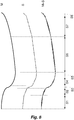
- a cross-sectional profile of the segments of Fig. 7 is shown, taken along the longitudinal or spanwise axis of the mould geometry 70.
- the mould geometry 70 is illustrated at the plot M, the segments are indicated at the plot S showing the substantially planar or straight-line spanwise projection of the segments, with the mould geometry and the segments superimposed in the plot M+S.
- the segments S1-S8 are selected to follow the curvature of the mould surface, such that the error margin between the substantially planar spanwise direction of the segments S1-S8 and the actual mould geometry surface for that section of the segment is maintained below a threshold value, e.g. using a bet-fit algorithm.
- the segments are selected such that the spanwise planar or straight-line surface defined by the sections follows the curved surface profile within a tolerance margin.
- said tolerance margin is within approximately 10 mm, preferably within approximately 5 mm, further preferably within approximately 1 mm.
- the particular dimensions of the spanwise segments S1-S8 may vary based on the particular mould geometry used. For example, if the mould geometry is relatively straight and unchanging in the spanwise direction, the length of the individual spanwise segments may be relatively long in the spanwise direction while still satisfying best-fit conditions. By contrast, for a pre-bent wind turbine blade, the mould geometry may have a large pre-bend in the spanwise direction, which may require a relatively large number of spanwise segments to accurately follow the pre-bend curvature of the mould geometry. In the example shown in Fig. 8 , it can be seen that a relatively large number of segments may be used to approximate a relatively small spanwise distance in regions of relatively high spanwise curvature.
- a mould geometry having relatively shallow camber or curvature may require a lower number of spanwise segments, as the mould geometry may be approximated within acceptable best-fit threshold margins using a smaller number of segments or sections than a mould geometry having a relatively more complex curvature or mould shape.
- the spanwise segments define cutting templates for a cutting apparatus, such that an approximation of a mould surface geometry profile may be cut or machined from a cutting blank element, step 104.
- the spanwise segments are preferably formed by a cut made in a surface of a blank element, the cut performed in a direction corresponding to a chordwise direction.
- a robotic or computer-controlled cutting apparatus in the form of a hot wire cutter is indicated at 74.
- the hot wire cutter 74 is provided on an articulated arm 76, to allow for the adjustment of the cutting angle provided by the cutter 74.
- a mould blank element 78 is provided, the mould blank element 78 preferably formed from a light-weight material such as a foam material, preferably formed from a polystyrene or expanded polystyrene (EPS) material.
- the hot wire cutter 74 is arranged to be passed through the mould blank element 78 to cut a surface into the blank.
- the orientation of the hot wire cutter 74 is controlled using the cutting templates provided from the approximation of the mould surface geometry profile, such that the surfaces cut into the blanks 78 correspond to the best-fit segments and/or sections of the approximation of the mould surface geometry profile.
- the cutting apparatus is passed through the mould blank element 78 to form cut mould elements 80 having a cut surface 82 defined thereon, Fig. 10 . While the example of Fig. 10 illustrates a substantially planar cut surface 82, it will be understood that the cutting apparatus may be arranged to provide curved surfaces, such as in the chordwise direction of the spanwise segments S1-S8.
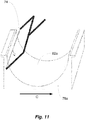
- a hot wire cutter 74 is shown forming a curved cut surface 82a from a mould blank element 78a.
- the hot wire cutter 74 performs a substantially straight-line cut across the length of the cutter itself, which corresponds with the spanwise direction of the mould geometry.
- the depth of the cut performed by the hot wire cutter 74 into the mould blank element 78a can be varied during cutting, resulting in a curved surface profile in the direction of the cut C, which corresponds with the chordwise direction of the mould geometry.
- separate cut mould elements 80 which have been cut using chordwise cuts based on different spanwise segments can be arranged in sequence such that the cut surfaces 82 of the cut mould elements 80 together define a consolidated wind turbine blade mould surface 84, wherein the consolidated wind turbine blade mould surface substantially corresponds to the desired mould geometry 70.
- each spanwise segment S1-S8 may define a cutting template having a plurality of separate cutting orientations and/or cutting depths within the cutting template in the chordwise direction, based on a best-fit orientation calculated for the area within that spanwise segment.
- a single cutting operation may be performed for each spanwise segment of the mould profile, the cutting apparatus making a pass through the blank 78 in a direction corresponding to the chordwise direction of the mould profile.
- the mould blank elements 78 may be initially provided to match with the number and outline dimensions of the separate spanwise segments S1-S8.
- separate cutting templates may be defined by a plurality of chordwise or transverse sections, wherein separate cutting operations are performed for each of the chordwise sections.
- the provided mould geometry 70 may be divided into a plurality of sequential spanwise segments, indicated as segments S1'-S7' in Fig. 13 .
- each of the segments may be further divided into a plurality of chordwise sections, indicated generally at C.
- the orientation and dimensions of the chordwise sections are selected to closely follow the surface profile of the desired mould geometry 70 for that segment of the mould.
- the chordwise sections may be arranged as substantially planar sections, but it will be understood that the section may define a degree of curvature or twist in the spanwise and/or chordwise directions.
- the cutting direction of the mould blank elements may be performed in a direction corresponding to the spanwise direction of the mould geometry 70, and/or in a direction corresponding to the chordwise direction of the mould geometry 70.
- a spanwise cutting direction may be more effective method of cutting for areas of the blade geometry having relatively complex curvature, e.g. around the areas of max chord and/or in the area of the tip region, where the spanwise profile of the mould geometry varies considerably along the chordwise direction.
- a chordwise straight line cut e.g. as illustrated in Fig. 11
- a number of different segments may be required along the chordwise direction of the spanwise segment, to account for changes in the cross-sectional spanwise profile of the segment.
- Fig. 14 the cross-sectional profile of a sample segment is shown, taken in the chordwise direction across a portion of a mould geometry.
- a plurality of chordwise sections D1-D4 are selected to follow the curvature of the mould surface along the chordwise direction, such that the error margin between the substantially planar chordwise section and the actual mould surface for that section of the segment is maintained below a threshold value, e.g. using a bet-fit algorithm.
- each cut mould element 80 may define a single chordwise section of the divided mould geometry, as indicated in the cut mould element 80 shown in Fig. 10 . Accordingly, the consolidated mould surface can be formed from a patchwork assembly of each of the individual cut mould elements 80.
- separate cut mould elements 80 which have been cut based on different spanwise and chordwise segments can be arranged in sequence such that the cut surfaces 82 of the cut mould elements 80 together define a consolidated wind turbine blade mould surface 84', wherein the consolidated wind turbine blade mould surface substantially corresponds to the desired mould geometry 70.
- the cuts may be made in any suitable direction on the mould blank elements relative to the desired mould geometry, e.g. (a) in a spanwise or longitudinal direction, substantially parallel to the longitudinal axis of a wind turbine blade mould between a root end and a tip end of such a mould; (b) in a chordwise or transverse direction, extending between the leading edge and trailing edge of a wind turbine blade mould; or (c) a combination of cuts in both spanwise and chordwise directions.
- FIG. 16 and 17 A further embodiment of the method of the invention is illustrated in Figs. 16 and 17 .
- Fig. 16 an alternative approach to the division of the mould geometry 70 is shown.
- the division results in the provision of a plurality of sequential spanwise segments S1"-S7".
- the segments are preferably formed from a mould blank element using a chordwise cut, as shown in Fig. 11 .
- Such segments may be arranged to use a single mould blank element between the leading edge and the trailing edge of the mould, and/or to have a relatively long length in the spanwise direction.
- the spanwise segments may be further divided into a plurality of sequential chordwise segments, indicated generally as C2", C3", C7".
- the surface profile may be formed by the cutting of mould blank elements in a spanwise and/or a chordwise cutting direction.
- Fig. 17 illustrates a sample wind turbine blade mould 84" formed from a division of mould geometry similar to Fig. 16 .
- those areas of the mould having a steady or relatively constant curvature, such as at the root end of the mould and the mainboard sections of the mould may be formed from single cut mould elements formed using chordwise cuts of mould blank elements.
- areas of the mould having a relatively complex or changing curvature such as in the transition region, at the area of max chord and at the tip end of the mould, may be formed from a plurality of different chordwise cut mould elements formed using chordwise and/or spanwise cuts of mould blank elements.
- cut directions are described in the above embodiments as made in a chordwise and/or spanwise direction, it will be understood that the cut direction may be made in a direction generally in line with a chordwise and/or spanwise direction, e.g. within +/- 20 degrees of a spanwise or a chordwise axis at the location of the cut.
- the cut may be performed along a sweeping or curved direction, e.g. from a substantially chordwise direction to a substantially spanwise direction, or vice versa. Such cuts may be appropriate in areas of relatively high curvature, e.g. in the region of the tip end of the mould geometry.
- start and/or end locations of the cuts may be arranged to define the profile of the leading and/or the trailing edges of that segment of the mould geometry. Such an adjustment of the start and/or end locations may be accomplished through appropriate sweeping or variation of the cut direction for that segment of the mould geometry.
- the assembly of the individual cut mould elements 80 may be secured together using any suitable attachment means, e.g. bolting, adhesive, snap-fit connections, etc.
- the consolidated profile presented by the assembled cut surfaces 82 may be within tolerance limits and sufficiently accurate to present a finished mould surface.
- a coating layer is applied to the consolidated profile, step 108, to present a finished mould surface suitable to receive material for the moulding of a wind turbine blade shell.
- the coating layer may also act as an adhesive, to bond the separate cut mould elements 80 together to form a consolidated wind turbine blade mould.
- the coating layer comprises an elastomer coating material, preferably a polyurea coating, which can provide a resilient coating resistant to operational wear-and-tear.
- a finishing operation may be performed on the assembled cut surfaces of the cut mould elements, and/or on the coating layer applied to the consolidated mould surface.
- the finishing operation may comprise a further cutting, grinding, and/or polishing operation, to provide for a smooth surface of the finished mould, and to resolve any surface discontinuities between the edges of the assembled cut surfaces.
- FIG. 18 A further aspect of the invention is illustrated in the process diagram of Fig. 18 .
- the method may comprise a process wherein a flexible cutting device is reshaped to provide a non-planar cutting profile. The reshaping may be performed based on the desired cut geometry, to ensure that the end product accurately corresponds to the desired equipment profile.
- a desired element geometry is provided, which may define the profile shape of, for example, a wind turbine blade mould surface or a wind turbine blade mould plug geometry.
- a geometry may be received by a suitable controller for the equipment manufacturing process, and may be provided from any suitable system, for example as a result of the equipment design process, and/or through appropriate scanning and mapping of an existing equipment profile.
- a reshaping apparatus is indicated at 86.
- the reshaping apparatus 86 comprises upper and lower arrays of linear actuators 88a,88b.
- the actuator arrays 88a,88b are arranged in parallel series, and are moveably along parallel axes, e.g. along the horizontal axis indicated at X in Fig. 19 .
- a first flexible membrane 90a is provided adjacent the lower side of the upper array of actuators 88a and a second flexible membrane 90b is provided adjacent the upper side of the lower array of actuators 88b.
- the flexible membranes 90a,90b may be loosely connected to the actuators, or simply held in position adjacent the respective sides of the arrays 88a,88b.
- the respective flexible membranes 90a,90b may be deformed to assume a profile shape. Such adjustment is performed based on the desired element geometry of the wind turbine blade mould or mould plug, at step 202. As a result, the shaped flexible membranes 90a,90b form a pair of opposed bearing or clamping surfaces for the re-shaping of a flexible cutting device.
- the actuator arrays 88a,88b are preferably adjusted to form complementarily-shaped bearing surfaces of the reshaping apparatus 86. While the apparatus 86 shown utilises a pair of opposed bearing surfaces, in an alternative configuration the apparatus may be provided with a single adjustable bearing surface, wherein a flexible cutting device may be applied against the single surface and/or the single surface may be pressed against the cutting device.
- the actuator arrays 88a,88b and the respective flexible membranes 90a,90b are provided as separate sub-assemblies of the reshaping apparatus 86, such that the upper array 88a and membrane 90a may be moved relative to the lower array 88b and membrane 90b, preferably in a clamping action, following the arrows indicated at Y in Fig. 19 .
- a flexible cutting device in the form of a hot wire cutter 74a is positioned between the opposed shaped flexible membranes 90a,90b.
- a receiving channel may be provided in the surface of at least one of the flexible membranes 90a,90b, to provide for accurate positioning of the wire between the opposed surfaces.
- Fig. 19 illustrates the reshaping of a wire cutter device, it will be understood that alternative types of cutting devices may be shaped in the apparatus.
- step 206 the opposed clamping surfaces are brought together in a clamping action, as indicated by the arrows Y in Fig. 19 .
- the action of clamping the surfaces defined by the flexible membranes 90a,90b against the wire cutter 74a acts to reshape and deform the wire cutter 74a to assume the profile defined by the flexible membranes 90a,90b and the adjusted actuators 88a,88b.
- the clamping surfaces are applied against the wire cutter 74a for a time period and a clamping pressure suitable to ensure that the wire cutter 74a will retain the profile of the clamping surfaces.
- the clamping surfaces are then opened, step 208, and the reshaped wire cutter removed from the apparatus 86.
- the reshaped wire cutter may then be used in the manufacturing method as shown in Figs. 9 and 10 to provide for cut mould elements having a relatively complex or curved cut profile geometry.
- the ability to reshape the wire cutter to form mould elements with curved surfaces means that the provision of the mould geometry into separate geometrical slices is not as limited compared to the method utilising substantially flat planar cut surfaces with limited tolerance ranges. Accordingly, the mould geometry can be recreated using a smaller number of relatively larger slices, thereby reducing the number of different mould blank elements which are required, and the number of boundaries between adjacent mould elements which may require smoothing, etc.
- FIG. 20 An example of the advantages presented by the use of the reshaped wire cutter is illustrated in Fig. 20 , wherein a cross-sectional profile taken along the longitudinal or spanwise axis of a mould geometry 70 is shown.
- the mould geometry 70 is illustrated at the plot M, the segments are indicated at the plot S showing the substantially planar or straight-line spanwise projection of the segments, with the mould geometry and the segments superimposed in the plot M+S.
Landscapes
- Engineering & Computer Science (AREA)
- Mechanical Engineering (AREA)
- Manufacturing & Machinery (AREA)
- Wind Motors (AREA)
- Turbine Rotor Nozzle Sealing (AREA)
Applications Claiming Priority (3)
| Application Number | Priority Date | Filing Date | Title |
|---|---|---|---|
| EP14181425 | 2014-08-19 | ||
| GBGB1415217.7A GB201415217D0 (en) | 2014-08-28 | 2014-08-28 | A method of manufacturing equipment |
| PCT/EP2015/068966 WO2016026867A1 (en) | 2014-08-19 | 2015-08-18 | A method of manufacturing a mould for a wind turbine blade shell |
Publications (2)
| Publication Number | Publication Date |
|---|---|
| EP3183102A1 EP3183102A1 (en) | 2017-06-28 |
| EP3183102B1 true EP3183102B1 (en) | 2019-11-13 |
Family
ID=53872067
Family Applications (1)
| Application Number | Title | Priority Date | Filing Date |
|---|---|---|---|
| EP15750766.6A Active EP3183102B1 (en) | 2014-08-19 | 2015-08-18 | A method of manufacturing a mould for a wind turbine blade shell |
Country Status (9)
| Country | Link |
|---|---|
| US (1) | US20170274563A1 (ko) |
| EP (1) | EP3183102B1 (ko) |
| CN (1) | CN107073757B (ko) |
| BR (1) | BR112017003246A2 (ko) |
| CA (1) | CA2958564A1 (ko) |
| DK (1) | DK3183102T3 (ko) |
| ES (1) | ES2773673T3 (ko) |
| MX (1) | MX380984B (ko) |
| WO (1) | WO2016026867A1 (ko) |
Families Citing this family (18)
| Publication number | Priority date | Publication date | Assignee | Title |
|---|---|---|---|---|
| DK2407292T3 (da) * | 2010-07-14 | 2013-12-16 | Siemens Ag | Negativ form omfattende forud definerede skumblokke til støbning af en komponent samt fremgangsmåde til fremstilling af den negative form |
| EP3172022B1 (en) * | 2014-07-25 | 2019-10-23 | Suzhou Red Maple Wind Blade Mould Co., Ltd | Mould for moulding wind turbine blade and assembly of mould |
| WO2016153588A1 (en) * | 2015-03-25 | 2016-09-29 | Sikorsky Aircraft Corporation | Tools and processes for manufacturing parts employing additive manufacturing |
| CN108327133B (zh) * | 2017-12-25 | 2020-02-07 | 明阳智慧能源集团股份公司 | 一种风力发电分段叶片的成型方法 |
| DK3746279T3 (da) * | 2018-02-01 | 2023-12-11 | Lm Wind Power As | Sammenkobling af formdele |
| WO2019200356A1 (en) * | 2018-04-12 | 2019-10-17 | Resource West, Inc. | Impeller for ambient water evaporators, and related system and method |
| EP3787881A4 (en) * | 2018-05-04 | 2021-12-29 | TPI Composites, Inc. | Perimeter plates for wind turbine blade manufacturing |
| CN109016273A (zh) * | 2018-07-20 | 2018-12-18 | 中材科技(邯郸)风电叶片有限公司 | 金属粘接角工装 |
| DE102018009331A1 (de) * | 2018-11-28 | 2020-05-28 | Senvion Gmbh | Rotorblattform und Verfahren zur Herstellung eines Rotorblattes für eine Windenergieanlage sowie Windenergieanlage |
| BR112021016970A2 (pt) * | 2019-02-28 | 2021-11-23 | Lm Wind Power As | Molde de pré-forma flexível para a fabricação de uma pré-forma para uma lâmina de turbina eólica |
| EP3715080A1 (en) | 2019-03-26 | 2020-09-30 | Siemens Gamesa Renewable Energy A/S | Modular molding device, molding system and method for creating a mold for a blade segment of a wind turbine blade of a wind turbine |
| CN110851967B (zh) * | 2019-10-31 | 2023-04-18 | 山西大学 | 非完整测量数据下的空心涡轮叶片精铸蜡型模型重构方法 |
| CN111070729B (zh) * | 2019-11-12 | 2021-10-01 | 洛阳双瑞风电叶片有限公司 | 一种风电叶片腹板模具逆向建模的制作方法 |
| CN113085062A (zh) * | 2021-03-18 | 2021-07-09 | 中复连众(包头)复合材料有限公司 | 一种风电叶片后缘粘接造型腻刀截面取型的制备方法 |
| CN113579643A (zh) * | 2021-06-30 | 2021-11-02 | 南通盛迈思科技有限公司 | 一种大型非标景观模具工件生产工艺 |
| CN114138012B (zh) * | 2021-11-23 | 2024-09-10 | 复亚智能技术发展(江苏)有限公司 | 一种风机叶片巡检方法、装置、设备及存储介质 |
| CN114011990B (zh) * | 2022-01-06 | 2022-03-04 | 点夺机电工程江苏有限公司 | 一种具有嵌套冲杆结构的小型曲面叶片冲压成型一体机 |
| US12053924B1 (en) * | 2023-05-11 | 2024-08-06 | Thermwood Corporation | Constructing parts using cut layer additive manufacturing |
Family Cites Families (12)
| Publication number | Priority date | Publication date | Assignee | Title |
|---|---|---|---|---|
| GB191514739A (en) * | 1915-10-19 | 1916-06-22 | Norman William Godfrey | An Improved Method of and Means for Casting Metal Window Frames and the like. |
| US4425468A (en) * | 1981-12-31 | 1984-01-10 | Ppg Industries, Inc. | Polyurea-polyurethane acrylate polymer dispersions |
| US4675825A (en) * | 1984-10-30 | 1987-06-23 | Dementhon Daniel F | Computer-controlled peripheral shaping system |
| DE19900950C1 (de) * | 1999-01-13 | 2000-05-31 | Daimler Chrysler Ag | Verfahren zum schrittweisen Optimieren eines Formwerkzeuges |
| US7049548B1 (en) * | 2005-03-21 | 2006-05-23 | The Boeing Company | System and method for processing a preform vacuum vessel to produce a structural assembly |
| CN101585215A (zh) * | 2009-04-03 | 2009-11-25 | 上海同韵环保能源科技有限公司 | 风力发电机组叶片模具液压翻转系统 |
| EP2283996A1 (en) * | 2009-08-13 | 2011-02-16 | Siemens Aktiengesellschaft | Method and arrangement to produce a wind-turbine-blade |
| EP2316629B1 (en) * | 2009-10-27 | 2012-05-23 | Lm Glasfiber A/S | Modular mould system for manufacturing a shell part |
| CN101767463A (zh) * | 2009-12-29 | 2010-07-07 | 无锡天奇竹风科技有限公司 | 快速脱模用真空材料模块及其应用 |
| US20120090790A1 (en) * | 2011-11-08 | 2012-04-19 | Ge Wind Energy Gmbh | Methods of manufacturing tooling structures |
| WO2013153413A1 (en) * | 2012-04-12 | 2013-10-17 | Lipoczi Gergely | Modular system for producing prototypes and moulds |
| DE202014000999U1 (de) * | 2014-01-31 | 2014-04-09 | Windnovation Engineering Solutions Gmbh | Vorrichtung zur Herstellung von Rotorblattschalen |
-
2015
- 2015-08-18 MX MX2017001819A patent/MX380984B/es unknown
- 2015-08-18 BR BR112017003246A patent/BR112017003246A2/pt not_active Application Discontinuation
- 2015-08-18 CN CN201580056719.XA patent/CN107073757B/zh not_active Expired - Fee Related
- 2015-08-18 DK DK15750766.6T patent/DK3183102T3/da active
- 2015-08-18 CA CA2958564A patent/CA2958564A1/en not_active Abandoned
- 2015-08-18 WO PCT/EP2015/068966 patent/WO2016026867A1/en not_active Ceased
- 2015-08-18 EP EP15750766.6A patent/EP3183102B1/en active Active
- 2015-08-18 US US15/503,772 patent/US20170274563A1/en not_active Abandoned
- 2015-08-18 ES ES15750766T patent/ES2773673T3/es active Active
Non-Patent Citations (1)
| Title |
|---|
| None * |
Also Published As
| Publication number | Publication date |
|---|---|
| CA2958564A1 (en) | 2016-02-25 |
| WO2016026867A1 (en) | 2016-02-25 |
| CN107073757A (zh) | 2017-08-18 |
| MX2017001819A (es) | 2018-02-23 |
| EP3183102A1 (en) | 2017-06-28 |
| ES2773673T3 (es) | 2020-07-14 |
| MX380984B (es) | 2025-03-12 |
| US20170274563A1 (en) | 2017-09-28 |
| DK3183102T3 (da) | 2020-02-24 |
| CN107073757B (zh) | 2021-10-12 |
| BR112017003246A2 (pt) | 2017-11-28 |
Similar Documents
| Publication | Publication Date | Title |
|---|---|---|
| EP3183102B1 (en) | A method of manufacturing a mould for a wind turbine blade shell | |
| EP3475068B1 (en) | Manufacture of a wind turbine blade | |
| EP3475061B1 (en) | Wind turbine blade with improved glue joints and related method | |
| EP2778390B1 (en) | Tool and method for scarfing a wind turbine rotor blade segment | |
| EP2603376B1 (en) | Apparatus and method for forming a trailing edge of a wind turbine blade and trailing edge component. | |
| EP3890954B1 (en) | Improvements relating to wind turbine blade manufacture | |
| EP2809499B1 (en) | A system and method for manufacturing a wind turbine blade | |
| US8597015B2 (en) | Airfoil manufacturing system | |
| CN102555116A (zh) | 用于生产转子叶片的方法和装置 | |
| US10625450B2 (en) | Wind turbine blade | |
| US11644005B2 (en) | Wind turbine blade comprising a root end structure with a pultruded element having a transition portion | |
| EP3126127B1 (en) | A method and apparatus for manufacturing a part of a wind turbine blade | |
| CN119585521A (zh) | 用于风力涡轮机叶片的叶片组件、风力涡轮机以及用于建造风力涡轮机叶片的方法 | |
| EP2915997B1 (en) | Method for calculating and correcting the angle of attack in a wind turbine farm | |
| US20240009788A1 (en) | Methods and devices for post mould processing of a composite structure | |
| CN204003280U (zh) | 用于斜切转子叶片部段的工具 |
Legal Events
| Date | Code | Title | Description |
|---|---|---|---|
| STAA | Information on the status of an ep patent application or granted ep patent |
Free format text: STATUS: THE INTERNATIONAL PUBLICATION HAS BEEN MADE |
|
| PUAI | Public reference made under article 153(3) epc to a published international application that has entered the european phase |
Free format text: ORIGINAL CODE: 0009012 |
|
| STAA | Information on the status of an ep patent application or granted ep patent |
Free format text: STATUS: REQUEST FOR EXAMINATION WAS MADE |
|
| 17P | Request for examination filed |
Effective date: 20170315 |
|
| AK | Designated contracting states |
Kind code of ref document: A1 Designated state(s): AL AT BE BG CH CY CZ DE DK EE ES FI FR GB GR HR HU IE IS IT LI LT LU LV MC MK MT NL NO PL PT RO RS SE SI SK SM TR |
|
| AX | Request for extension of the european patent |
Extension state: BA ME |
|
| DAX | Request for extension of the european patent (deleted) | ||
| STAA | Information on the status of an ep patent application or granted ep patent |
Free format text: STATUS: EXAMINATION IS IN PROGRESS |
|
| 17Q | First examination report despatched |
Effective date: 20180320 |
|
| GRAP | Despatch of communication of intention to grant a patent |
Free format text: ORIGINAL CODE: EPIDOSNIGR1 |
|
| STAA | Information on the status of an ep patent application or granted ep patent |
Free format text: STATUS: GRANT OF PATENT IS INTENDED |
|
| INTG | Intention to grant announced |
Effective date: 20190605 |
|
| GRAS | Grant fee paid |
Free format text: ORIGINAL CODE: EPIDOSNIGR3 |
|
| GRAA | (expected) grant |
Free format text: ORIGINAL CODE: 0009210 |
|
| STAA | Information on the status of an ep patent application or granted ep patent |
Free format text: STATUS: THE PATENT HAS BEEN GRANTED |
|
| AK | Designated contracting states |
Kind code of ref document: B1 Designated state(s): AL AT BE BG CH CY CZ DE DK EE ES FI FR GB GR HR HU IE IS IT LI LT LU LV MC MK MT NL NO PL PT RO RS SE SI SK SM TR |
|
| REG | Reference to a national code |
Ref country code: CH Ref legal event code: EP Ref country code: AT Ref legal event code: REF Ref document number: 1201192 Country of ref document: AT Kind code of ref document: T Effective date: 20191115 |
|
| REG | Reference to a national code |
Ref country code: DE Ref legal event code: R096 Ref document number: 602015041664 Country of ref document: DE |
|
| REG | Reference to a national code |
Ref country code: IE Ref legal event code: FG4D |
|
| REG | Reference to a national code |
Ref country code: DK Ref legal event code: T3 Effective date: 20200217 |
|
| REG | Reference to a national code |
Ref country code: NL Ref legal event code: MP Effective date: 20191113 |
|
| REG | Reference to a national code |
Ref country code: LT Ref legal event code: MG4D |
|
| PG25 | Lapsed in a contracting state [announced via postgrant information from national office to epo] |
Ref country code: SE Free format text: LAPSE BECAUSE OF FAILURE TO SUBMIT A TRANSLATION OF THE DESCRIPTION OR TO PAY THE FEE WITHIN THE PRESCRIBED TIME-LIMIT Effective date: 20191113 Ref country code: LV Free format text: LAPSE BECAUSE OF FAILURE TO SUBMIT A TRANSLATION OF THE DESCRIPTION OR TO PAY THE FEE WITHIN THE PRESCRIBED TIME-LIMIT Effective date: 20191113 Ref country code: NL Free format text: LAPSE BECAUSE OF FAILURE TO SUBMIT A TRANSLATION OF THE DESCRIPTION OR TO PAY THE FEE WITHIN THE PRESCRIBED TIME-LIMIT Effective date: 20191113 Ref country code: FI Free format text: LAPSE BECAUSE OF FAILURE TO SUBMIT A TRANSLATION OF THE DESCRIPTION OR TO PAY THE FEE WITHIN THE PRESCRIBED TIME-LIMIT Effective date: 20191113 Ref country code: BG Free format text: LAPSE BECAUSE OF FAILURE TO SUBMIT A TRANSLATION OF THE DESCRIPTION OR TO PAY THE FEE WITHIN THE PRESCRIBED TIME-LIMIT Effective date: 20200213 Ref country code: NO Free format text: LAPSE BECAUSE OF FAILURE TO SUBMIT A TRANSLATION OF THE DESCRIPTION OR TO PAY THE FEE WITHIN THE PRESCRIBED TIME-LIMIT Effective date: 20200213 Ref country code: PT Free format text: LAPSE BECAUSE OF FAILURE TO SUBMIT A TRANSLATION OF THE DESCRIPTION OR TO PAY THE FEE WITHIN THE PRESCRIBED TIME-LIMIT Effective date: 20200313 Ref country code: PL Free format text: LAPSE BECAUSE OF FAILURE TO SUBMIT A TRANSLATION OF THE DESCRIPTION OR TO PAY THE FEE WITHIN THE PRESCRIBED TIME-LIMIT Effective date: 20191113 Ref country code: GR Free format text: LAPSE BECAUSE OF FAILURE TO SUBMIT A TRANSLATION OF THE DESCRIPTION OR TO PAY THE FEE WITHIN THE PRESCRIBED TIME-LIMIT Effective date: 20200214 Ref country code: LT Free format text: LAPSE BECAUSE OF FAILURE TO SUBMIT A TRANSLATION OF THE DESCRIPTION OR TO PAY THE FEE WITHIN THE PRESCRIBED TIME-LIMIT Effective date: 20191113 |
|
| PG25 | Lapsed in a contracting state [announced via postgrant information from national office to epo] |
Ref country code: HR Free format text: LAPSE BECAUSE OF FAILURE TO SUBMIT A TRANSLATION OF THE DESCRIPTION OR TO PAY THE FEE WITHIN THE PRESCRIBED TIME-LIMIT Effective date: 20191113 Ref country code: RS Free format text: LAPSE BECAUSE OF FAILURE TO SUBMIT A TRANSLATION OF THE DESCRIPTION OR TO PAY THE FEE WITHIN THE PRESCRIBED TIME-LIMIT Effective date: 20191113 Ref country code: IS Free format text: LAPSE BECAUSE OF FAILURE TO SUBMIT A TRANSLATION OF THE DESCRIPTION OR TO PAY THE FEE WITHIN THE PRESCRIBED TIME-LIMIT Effective date: 20200313 |
|
| PG25 | Lapsed in a contracting state [announced via postgrant information from national office to epo] |
Ref country code: AL Free format text: LAPSE BECAUSE OF FAILURE TO SUBMIT A TRANSLATION OF THE DESCRIPTION OR TO PAY THE FEE WITHIN THE PRESCRIBED TIME-LIMIT Effective date: 20191113 |
|
| REG | Reference to a national code |
Ref country code: ES Ref legal event code: FG2A Ref document number: 2773673 Country of ref document: ES Kind code of ref document: T3 Effective date: 20200714 |
|
| PG25 | Lapsed in a contracting state [announced via postgrant information from national office to epo] |
Ref country code: CZ Free format text: LAPSE BECAUSE OF FAILURE TO SUBMIT A TRANSLATION OF THE DESCRIPTION OR TO PAY THE FEE WITHIN THE PRESCRIBED TIME-LIMIT Effective date: 20191113 Ref country code: RO Free format text: LAPSE BECAUSE OF FAILURE TO SUBMIT A TRANSLATION OF THE DESCRIPTION OR TO PAY THE FEE WITHIN THE PRESCRIBED TIME-LIMIT Effective date: 20191113 Ref country code: EE Free format text: LAPSE BECAUSE OF FAILURE TO SUBMIT A TRANSLATION OF THE DESCRIPTION OR TO PAY THE FEE WITHIN THE PRESCRIBED TIME-LIMIT Effective date: 20191113 |
|
| REG | Reference to a national code |
Ref country code: DE Ref legal event code: R097 Ref document number: 602015041664 Country of ref document: DE |
|
| REG | Reference to a national code |
Ref country code: AT Ref legal event code: MK05 Ref document number: 1201192 Country of ref document: AT Kind code of ref document: T Effective date: 20191113 |
|
| PG25 | Lapsed in a contracting state [announced via postgrant information from national office to epo] |
Ref country code: SK Free format text: LAPSE BECAUSE OF FAILURE TO SUBMIT A TRANSLATION OF THE DESCRIPTION OR TO PAY THE FEE WITHIN THE PRESCRIBED TIME-LIMIT Effective date: 20191113 Ref country code: SM Free format text: LAPSE BECAUSE OF FAILURE TO SUBMIT A TRANSLATION OF THE DESCRIPTION OR TO PAY THE FEE WITHIN THE PRESCRIBED TIME-LIMIT Effective date: 20191113 |
|
| PLBE | No opposition filed within time limit |
Free format text: ORIGINAL CODE: 0009261 |
|
| STAA | Information on the status of an ep patent application or granted ep patent |
Free format text: STATUS: NO OPPOSITION FILED WITHIN TIME LIMIT |
|
| 26N | No opposition filed |
Effective date: 20200814 |
|
| PG25 | Lapsed in a contracting state [announced via postgrant information from national office to epo] |
Ref country code: AT Free format text: LAPSE BECAUSE OF FAILURE TO SUBMIT A TRANSLATION OF THE DESCRIPTION OR TO PAY THE FEE WITHIN THE PRESCRIBED TIME-LIMIT Effective date: 20191113 Ref country code: SI Free format text: LAPSE BECAUSE OF FAILURE TO SUBMIT A TRANSLATION OF THE DESCRIPTION OR TO PAY THE FEE WITHIN THE PRESCRIBED TIME-LIMIT Effective date: 20191113 |
|
| PG25 | Lapsed in a contracting state [announced via postgrant information from national office to epo] |
Ref country code: IT Free format text: LAPSE BECAUSE OF FAILURE TO SUBMIT A TRANSLATION OF THE DESCRIPTION OR TO PAY THE FEE WITHIN THE PRESCRIBED TIME-LIMIT Effective date: 20191113 |
|
| PG25 | Lapsed in a contracting state [announced via postgrant information from national office to epo] |
Ref country code: MC Free format text: LAPSE BECAUSE OF FAILURE TO SUBMIT A TRANSLATION OF THE DESCRIPTION OR TO PAY THE FEE WITHIN THE PRESCRIBED TIME-LIMIT Effective date: 20191113 |
|
| REG | Reference to a national code |
Ref country code: CH Ref legal event code: PL |
|
| PG25 | Lapsed in a contracting state [announced via postgrant information from national office to epo] |
Ref country code: CH Free format text: LAPSE BECAUSE OF NON-PAYMENT OF DUE FEES Effective date: 20200831 Ref country code: LI Free format text: LAPSE BECAUSE OF NON-PAYMENT OF DUE FEES Effective date: 20200831 Ref country code: LU Free format text: LAPSE BECAUSE OF NON-PAYMENT OF DUE FEES Effective date: 20200818 |
|
| REG | Reference to a national code |
Ref country code: BE Ref legal event code: MM Effective date: 20200831 |
|
| VS25 | Lapsed in a validation state [announced via postgrant information from nat. office to epo] |
Ref country code: MA Free format text: LAPSE BECAUSE OF FAILURE TO SUBMIT A TRANSLATION OF THE DESCRIPTION OR TO PAY THE FEE WITHIN THE PRESCRIBED TIME-LIMIT Effective date: 20191113 |
|
| PG25 | Lapsed in a contracting state [announced via postgrant information from national office to epo] |
Ref country code: FR Free format text: LAPSE BECAUSE OF NON-PAYMENT OF DUE FEES Effective date: 20200831 |
|
| PG25 | Lapsed in a contracting state [announced via postgrant information from national office to epo] |
Ref country code: IE Free format text: LAPSE BECAUSE OF NON-PAYMENT OF DUE FEES Effective date: 20200818 Ref country code: BE Free format text: LAPSE BECAUSE OF NON-PAYMENT OF DUE FEES Effective date: 20200831 |
|
| PGFP | Annual fee paid to national office [announced via postgrant information from national office to epo] |
Ref country code: ES Payment date: 20210901 Year of fee payment: 7 Ref country code: DE Payment date: 20210720 Year of fee payment: 7 Ref country code: DK Payment date: 20210722 Year of fee payment: 7 Ref country code: GB Payment date: 20210720 Year of fee payment: 7 |
|
| PG25 | Lapsed in a contracting state [announced via postgrant information from national office to epo] |
Ref country code: TR Free format text: LAPSE BECAUSE OF FAILURE TO SUBMIT A TRANSLATION OF THE DESCRIPTION OR TO PAY THE FEE WITHIN THE PRESCRIBED TIME-LIMIT Effective date: 20191113 Ref country code: MT Free format text: LAPSE BECAUSE OF FAILURE TO SUBMIT A TRANSLATION OF THE DESCRIPTION OR TO PAY THE FEE WITHIN THE PRESCRIBED TIME-LIMIT Effective date: 20191113 Ref country code: CY Free format text: LAPSE BECAUSE OF FAILURE TO SUBMIT A TRANSLATION OF THE DESCRIPTION OR TO PAY THE FEE WITHIN THE PRESCRIBED TIME-LIMIT Effective date: 20191113 |
|
| PG25 | Lapsed in a contracting state [announced via postgrant information from national office to epo] |
Ref country code: MK Free format text: LAPSE BECAUSE OF FAILURE TO SUBMIT A TRANSLATION OF THE DESCRIPTION OR TO PAY THE FEE WITHIN THE PRESCRIBED TIME-LIMIT Effective date: 20191113 |
|
| REG | Reference to a national code |
Ref country code: DE Ref legal event code: R119 Ref document number: 602015041664 Country of ref document: DE |
|
| REG | Reference to a national code |
Ref country code: DK Ref legal event code: EBP Effective date: 20220831 |
|
| GBPC | Gb: european patent ceased through non-payment of renewal fee |
Effective date: 20220818 |
|
| P01 | Opt-out of the competence of the unified patent court (upc) registered |
Effective date: 20230522 |
|
| PG25 | Lapsed in a contracting state [announced via postgrant information from national office to epo] |
Ref country code: DK Free format text: LAPSE BECAUSE OF NON-PAYMENT OF DUE FEES Effective date: 20220831 Ref country code: DE Free format text: LAPSE BECAUSE OF NON-PAYMENT OF DUE FEES Effective date: 20230301 |
|
| REG | Reference to a national code |
Ref country code: ES Ref legal event code: FD2A Effective date: 20230929 |
|
| PG25 | Lapsed in a contracting state [announced via postgrant information from national office to epo] |
Ref country code: GB Free format text: LAPSE BECAUSE OF NON-PAYMENT OF DUE FEES Effective date: 20220818 Ref country code: ES Free format text: LAPSE BECAUSE OF NON-PAYMENT OF DUE FEES Effective date: 20220819 |