EP3182096B1 - Kalibrierung und/oder fehlererkennung in einer optischen messvorrichtung für biologische proben - Google Patents
Kalibrierung und/oder fehlererkennung in einer optischen messvorrichtung für biologische proben Download PDFInfo
- Publication number
- EP3182096B1 EP3182096B1 EP15200769.6A EP15200769A EP3182096B1 EP 3182096 B1 EP3182096 B1 EP 3182096B1 EP 15200769 A EP15200769 A EP 15200769A EP 3182096 B1 EP3182096 B1 EP 3182096B1
- Authority
- EP
- European Patent Office
- Prior art keywords
- measurement
- measurement channel
- channel
- reference factor
- factors
- Prior art date
- Legal status (The legal status is an assumption and is not a legal conclusion. Google has not performed a legal analysis and makes no representation as to the accuracy of the status listed.)
- Active
Links
- 238000005259 measurement Methods 0.000 title claims description 592
- 230000003287 optical effect Effects 0.000 title claims description 194
- 238000001514 detection method Methods 0.000 title claims description 142
- 239000012472 biological sample Substances 0.000 title claims description 107
- 238000000034 method Methods 0.000 claims description 137
- 230000008569 process Effects 0.000 claims description 67
- 238000003780 insertion Methods 0.000 claims description 6
- 230000037431 insertion Effects 0.000 claims description 6
- 239000000523 sample Substances 0.000 description 25
- 230000008859 change Effects 0.000 description 19
- 238000012545 processing Methods 0.000 description 16
- 230000003068 static effect Effects 0.000 description 16
- 239000003153 chemical reaction reagent Substances 0.000 description 13
- 239000013307 optical fiber Substances 0.000 description 12
- 230000005540 biological transmission Effects 0.000 description 10
- 238000004458 analytical method Methods 0.000 description 9
- 238000012937 correction Methods 0.000 description 8
- 238000000338 in vitro Methods 0.000 description 5
- 239000000126 substance Substances 0.000 description 5
- 239000012491 analyte Substances 0.000 description 4
- 238000005345 coagulation Methods 0.000 description 4
- 230000015271 coagulation Effects 0.000 description 4
- 239000000835 fiber Substances 0.000 description 4
- 239000012530 fluid Substances 0.000 description 4
- 239000012634 fragment Substances 0.000 description 4
- 238000011534 incubation Methods 0.000 description 4
- 210000004027 cell Anatomy 0.000 description 3
- 238000006243 chemical reaction Methods 0.000 description 3
- 230000002950 deficient Effects 0.000 description 3
- 238000011068 loading method Methods 0.000 description 3
- 238000012986 modification Methods 0.000 description 3
- 230000004048 modification Effects 0.000 description 3
- 238000003753 real-time PCR Methods 0.000 description 3
- 239000008280 blood Substances 0.000 description 2
- 210000004369 blood Anatomy 0.000 description 2
- 238000005336 cracking Methods 0.000 description 2
- 230000007547 defect Effects 0.000 description 2
- 230000006866 deterioration Effects 0.000 description 2
- 230000007613 environmental effect Effects 0.000 description 2
- 239000007850 fluorescent dye Substances 0.000 description 2
- 230000010354 integration Effects 0.000 description 2
- 239000007788 liquid Substances 0.000 description 2
- 238000012544 monitoring process Methods 0.000 description 2
- 108020004707 nucleic acids Proteins 0.000 description 2
- 102000039446 nucleic acids Human genes 0.000 description 2
- 150000007523 nucleic acids Chemical class 0.000 description 2
- 230000005855 radiation Effects 0.000 description 2
- 230000004044 response Effects 0.000 description 2
- 239000007787 solid Substances 0.000 description 2
- 239000000758 substrate Substances 0.000 description 2
- 238000012360 testing method Methods 0.000 description 2
- 238000012546 transfer Methods 0.000 description 2
- 210000002700 urine Anatomy 0.000 description 2
- 206010003445 Ascites Diseases 0.000 description 1
- 238000000018 DNA microarray Methods 0.000 description 1
- 230000002411 adverse Effects 0.000 description 1
- 230000032683 aging Effects 0.000 description 1
- 210000004381 amniotic fluid Anatomy 0.000 description 1
- 239000000427 antigen Substances 0.000 description 1
- 102000036639 antigens Human genes 0.000 description 1
- 108091007433 antigens Proteins 0.000 description 1
- 238000003491 array Methods 0.000 description 1
- 210000003567 ascitic fluid Anatomy 0.000 description 1
- 238000003556 assay Methods 0.000 description 1
- 238000003705 background correction Methods 0.000 description 1
- 239000012620 biological material Substances 0.000 description 1
- 239000000969 carrier Substances 0.000 description 1
- 238000005119 centrifugation Methods 0.000 description 1
- 210000001175 cerebrospinal fluid Anatomy 0.000 description 1
- 238000004891 communication Methods 0.000 description 1
- 210000004748 cultured cell Anatomy 0.000 description 1
- 230000001934 delay Effects 0.000 description 1
- 230000001419 dependent effect Effects 0.000 description 1
- 238000002405 diagnostic procedure Methods 0.000 description 1
- 238000010586 diagram Methods 0.000 description 1
- 238000010790 dilution Methods 0.000 description 1
- 239000012895 dilution Substances 0.000 description 1
- 238000010494 dissociation reaction Methods 0.000 description 1
- 230000005593 dissociations Effects 0.000 description 1
- 238000004821 distillation Methods 0.000 description 1
- 239000000428 dust Substances 0.000 description 1
- 238000000295 emission spectrum Methods 0.000 description 1
- 230000005284 excitation Effects 0.000 description 1
- 238000001914 filtration Methods 0.000 description 1
- 229910052736 halogen Inorganic materials 0.000 description 1
- 150000002367 halogens Chemical class 0.000 description 1
- 230000002779 inactivation Effects 0.000 description 1
- 230000002452 interceptive effect Effects 0.000 description 1
- 238000012423 maintenance Methods 0.000 description 1
- 238000004949 mass spectrometry Methods 0.000 description 1
- 239000000463 material Substances 0.000 description 1
- 239000002207 metabolite Substances 0.000 description 1
- 210000004080 milk Anatomy 0.000 description 1
- 239000008267 milk Substances 0.000 description 1
- 235000013336 milk Nutrition 0.000 description 1
- 238000002156 mixing Methods 0.000 description 1
- 230000002085 persistent effect Effects 0.000 description 1
- 238000011112 process operation Methods 0.000 description 1
- 102000004169 proteins and genes Human genes 0.000 description 1
- 108090000623 proteins and genes Proteins 0.000 description 1
- 210000003296 saliva Anatomy 0.000 description 1
- 210000000582 semen Anatomy 0.000 description 1
- 238000000926 separation method Methods 0.000 description 1
- 238000012883 sequential measurement Methods 0.000 description 1
- 230000003595 spectral effect Effects 0.000 description 1
- 210000004243 sweat Anatomy 0.000 description 1
- 210000001179 synovial fluid Anatomy 0.000 description 1
- 210000001519 tissue Anatomy 0.000 description 1
Images


Classifications
-
- G—PHYSICS
- G01—MEASURING; TESTING
- G01N—INVESTIGATING OR ANALYSING MATERIALS BY DETERMINING THEIR CHEMICAL OR PHYSICAL PROPERTIES
- G01N21/00—Investigating or analysing materials by the use of optical means, i.e. using sub-millimetre waves, infrared, visible or ultraviolet light
- G01N21/17—Systems in which incident light is modified in accordance with the properties of the material investigated
- G01N21/25—Colour; Spectral properties, i.e. comparison of effect of material on the light at two or more different wavelengths or wavelength bands
- G01N21/251—Colorimeters; Construction thereof
- G01N21/253—Colorimeters; Construction thereof for batch operation, i.e. multisample apparatus
-
- G—PHYSICS
- G01—MEASURING; TESTING
- G01N—INVESTIGATING OR ANALYSING MATERIALS BY DETERMINING THEIR CHEMICAL OR PHYSICAL PROPERTIES
- G01N21/00—Investigating or analysing materials by the use of optical means, i.e. using sub-millimetre waves, infrared, visible or ultraviolet light
- G01N21/01—Arrangements or apparatus for facilitating the optical investigation
-
- G—PHYSICS
- G01—MEASURING; TESTING
- G01N—INVESTIGATING OR ANALYSING MATERIALS BY DETERMINING THEIR CHEMICAL OR PHYSICAL PROPERTIES
- G01N35/00—Automatic analysis not limited to methods or materials provided for in any single one of groups G01N1/00 - G01N33/00; Handling materials therefor
- G01N35/00584—Control arrangements for automatic analysers
- G01N35/00594—Quality control, including calibration or testing of components of the analyser
- G01N35/00693—Calibration
-
- G—PHYSICS
- G01—MEASURING; TESTING
- G01N—INVESTIGATING OR ANALYSING MATERIALS BY DETERMINING THEIR CHEMICAL OR PHYSICAL PROPERTIES
- G01N21/00—Investigating or analysing materials by the use of optical means, i.e. using sub-millimetre waves, infrared, visible or ultraviolet light
- G01N21/17—Systems in which incident light is modified in accordance with the properties of the material investigated
- G01N21/25—Colour; Spectral properties, i.e. comparison of effect of material on the light at two or more different wavelengths or wavelength bands
- G01N21/27—Colour; Spectral properties, i.e. comparison of effect of material on the light at two or more different wavelengths or wavelength bands using photo-electric detection ; circuits for computing concentration
- G01N21/274—Calibration, base line adjustment, drift correction
-
- G—PHYSICS
- G01—MEASURING; TESTING
- G01N—INVESTIGATING OR ANALYSING MATERIALS BY DETERMINING THEIR CHEMICAL OR PHYSICAL PROPERTIES
- G01N21/00—Investigating or analysing materials by the use of optical means, i.e. using sub-millimetre waves, infrared, visible or ultraviolet light
- G01N21/17—Systems in which incident light is modified in accordance with the properties of the material investigated
- G01N21/25—Colour; Spectral properties, i.e. comparison of effect of material on the light at two or more different wavelengths or wavelength bands
- G01N21/31—Investigating relative effect of material at wavelengths characteristic of specific elements or molecules, e.g. atomic absorption spectrometry
-
- G—PHYSICS
- G01—MEASURING; TESTING
- G01N—INVESTIGATING OR ANALYSING MATERIALS BY DETERMINING THEIR CHEMICAL OR PHYSICAL PROPERTIES
- G01N21/00—Investigating or analysing materials by the use of optical means, i.e. using sub-millimetre waves, infrared, visible or ultraviolet light
- G01N21/17—Systems in which incident light is modified in accordance with the properties of the material investigated
- G01N21/47—Scattering, i.e. diffuse reflection
- G01N21/4738—Diffuse reflection, e.g. also for testing fluids, fibrous materials
- G01N21/474—Details of optical heads therefor, e.g. using optical fibres
-
- G—PHYSICS
- G01—MEASURING; TESTING
- G01N—INVESTIGATING OR ANALYSING MATERIALS BY DETERMINING THEIR CHEMICAL OR PHYSICAL PROPERTIES
- G01N21/00—Investigating or analysing materials by the use of optical means, i.e. using sub-millimetre waves, infrared, visible or ultraviolet light
- G01N21/17—Systems in which incident light is modified in accordance with the properties of the material investigated
- G01N21/55—Specular reflectivity
-
- G—PHYSICS
- G01—MEASURING; TESTING
- G01N—INVESTIGATING OR ANALYSING MATERIALS BY DETERMINING THEIR CHEMICAL OR PHYSICAL PROPERTIES
- G01N35/00—Automatic analysis not limited to methods or materials provided for in any single one of groups G01N1/00 - G01N33/00; Handling materials therefor
- G01N35/02—Automatic analysis not limited to methods or materials provided for in any single one of groups G01N1/00 - G01N33/00; Handling materials therefor using a plurality of sample containers moved by a conveyor system past one or more treatment or analysis stations
- G01N35/026—Automatic analysis not limited to methods or materials provided for in any single one of groups G01N1/00 - G01N33/00; Handling materials therefor using a plurality of sample containers moved by a conveyor system past one or more treatment or analysis stations having blocks or racks of reaction cells or cuvettes
-
- G—PHYSICS
- G01—MEASURING; TESTING
- G01N—INVESTIGATING OR ANALYSING MATERIALS BY DETERMINING THEIR CHEMICAL OR PHYSICAL PROPERTIES
- G01N2201/00—Features of devices classified in G01N21/00
- G01N2201/12—Circuits of general importance; Signal processing
- G01N2201/127—Calibration; base line adjustment; drift compensation
Definitions
- This disclosure relates to the systems and methods for calibration and/or error detection in an optical measurement device for biological samples.
- optical measurement devices for biological samples can process a large number of samples in automated or semi-automated manner. This might include measuring optical properties of the sample in a plurality of different measurement positions or measurement channels and with a comparatively high throughput.
- an optical measurement device can include fairly complex mechanics to handle and process biological samples. The complexity of the automated or semi-automated optical measurement devices can lead to a multitude of errors and changes of the condition of the measurement device during operation.
- biological samples to be analyzed can be contained in cuvettes or other vessels. These cuvettes or other vessels might get damaged (e.g., crack or break) in the course of an automatic handling process.
- light used in the analysis process can be guided to and from a measurement channel or position by optical fibers. The fibers might move or break during operation of the optical measurement device.
- foreign objects might partially or completely block a measurement channel.
- qPCR quantitative PCR
- melt curve melting and/or association curve
- the instrument having at least one optical channel
- the instrument comprising: a fluorescence excitation source; a fluorescence detector having a signal output; an electronic analogue signal amplifier having an input coupled to said fluorescence detector signal output; and an analogue- to-digital converter (ADC) having analogue input coupled to an output of said analogue signal amplifier; further comprising a quantified automatic gain control (AGC) loop coupled between said signal output of said fluorescence detector and said analogue input of ADC, wherein said AGC loop is configured to apply a determined, numerical gain value to a fluorescence signal for said analogue input of said ADC; and a system to scale a digital output of said ADC responsive to said numerical gain value and to provide a digital fluorescence level signal from said scaled digital output.
- AGC quantified automatic gain control
- US 2013/0214177 A1 discloses a sample processing apparatus for processing one or more samples carried by a sample carrier such as a biochip.
- the apparatus comprises an optical reader having a plurality of optical detection channels whose gains are corrected during run-time by obtaining detection values using a gain-monitoring fixture.
- One of the detectors is used as a reference detector and a gain ratio determiner determines a ratio of the gain of each of the detectors relative to the gain of the reference detector.
- a method for calibration and/or error detection in an optical measurement device for biological samples having at least a first and a second measurement channel includes, between measurements of biological samples in the second measurement channel of the optical measurement device, repeatedly performing a reference factor update process including the steps of obtaining one or more current reference factors for the second measurement channel, each reference factor being indicative of a relationship between measurement signals in the first and second measurement channels of the optical measurement device, determining a detection signal of the first measurement channel, determining a detection signal of the second measurement channel, calculating an updated reference factor for the second measurement channel based on the first and second detection signals, comparing the updated reference factor with at least one of the one or more current reference factors and depending on the result of the comparison, either storing the updated reference factor as a new current reference factor for use in a later measurement in the second measurement channel or keeping the one or more current reference factors for use in a later measurement in the second measurement channel.
- the optical measurement device includes a first measurement channel, a second measurement channel, a detector configured to receive signals from the first and second measurement channels and a controller configured to, between measurements of biological samples in the second measurement channel of the optical measurement device, repeatedly perform a reference factor update process including the steps of obtaining one or more current reference factors for the second measurement channel, each reference factor being indicative of a relationship between measurement signals in the first and second measurement channels of the optical measurement device, determining a detection signal of the first measurement channel, determining a detection signal of the second measurement channel, calculating an updated reference factor for the second measurement channel based on the first and second detection signals, comparing the updated reference factor with at least one of the one or more current reference factors and depending on the result of the comparison, either storing the updated reference factor as a new current reference factor for use in a later measurement in the second measurement channel or keeping the one or more current reference factors for use in a later measurement in the second measurement channel.
- the method of the first general aspect of the present disclosure and the system of the second general aspect of the present disclosure can have one or more of the following advantages.
- a plurality or all measurement channels of an optical measurement device can be continuously monitored. Error conditions can be swiftly detected such that using defective measurement positions can be avoided. This can prevent conducting faulty measurements in some examples.
- defective measurement channels can be identified in a comparatively short time after an error has occurred.
- an optical measurement device can still be operated by using error-free measurement channels after an error in one or more measurement channels has been found. This might reduce the down-time of the optical measurement device.
- the techniques of the first and second general aspects of the present disclosure can be carried out continuously and comparatively non-intrusively in an optical measurement device. In this manner, a ratio between time that can be used for measuring operations and time that is used for maintenance can be improved in some examples.
- an optical measurement device can be operated for a longer time without significant deterioration of the measurement performance in some examples as a result of a continuous monitoring.
- the techniques of the first and second general aspects of the present disclosure can provide for a continuous correction of the detection signals of the optical measurement device in some examples.
- the properties of different components of the optical measurement device can change in time (or temporarily change) due to aging or changes in ambient conditions.
- the techniques of the first and second general aspects of the present disclosure can be employed to correct for these changes in some examples.
- this correction process can happen on a "per measurement channel basis" so that different changes of different measurement channels can be coped with.
- a relatively elaborate calibration process takes place only when the optical measurement devices are assembled or applied in the field for the first time.
- these devices might not be configured to monitor and correct for the changes of the device during its life time in an equally sophisticated manner. Therefore, measurement performance might degrade or extended down-time due to recalibration might be required in these devices.
- the technique of the first and second general aspects of the present disclosure can be adapted to a large variety of optical measurement devices in a fairly simple manner in some examples.
- reference factors can be generated and updated for each measurement channel of an optical measurement device independently from the reference factors of other measurement channels.
- differences between the multiple measurement channels of an optical measurement device can be taken into account "automatically" by the technique of the first and second general aspects in some examples.
- different measurement channels can have (fairly) different properties.
- a first measurement channel in which the optical fibers are bent in a smaller radius might deliver a lower amount of useful light and be more sensitive to changes in ambient conditions than a second measurement channel in which the optical fibers are less strongly bent.
- Such differences do not have to be explicitly taken into account when employing the techniques of the first and second general aspects of the present disclosure but can be dealt with automatically in some examples.
- the techniques of the first and second general aspects of the present disclosure can be used without substantial modifications in fiber based or free-space optical measurement devices, or in devices measuring in transmission, reflection or a different configuration.
- light includes but is not limited to radiation in the visible wavelength range.
- light can include radiation having a wavelength of over 200 nm and below 10.000 nm (for instance, a wavelength between 350 nm and 1500 nm).
- a measurement channel or a measurement position is configured so that a biological sample can be installed in a particular place and an optical measurement can be conducted on the biological sample.
- a measurement channel or a measurement position can include a mounting site adapted to mount a sample holder of a biological sample (e.g., a cuvette for a transmission measurement or a primary tube containing a biological sample).
- different measurement channels can be defined by different beams of a free-space optical system.
- different measurement channels can include predetermined areas on a microscope slide or other support substrate which can carry a biological sample to be analyzed, e.g. different wells of a multi-well plate.
- the term 'measurement channel' and 'measurement position' is not limited to a particular hardware setup of the optical measurement device.
- the term 'optical measurement device for biological samples' can include any manual, semi-automated or automated measurement device configured to conduct optical measurements on biological samples.
- an 'optical measurement device for biological samples' can include an analyzer or an analytical work cell for analyzing biological samples.
- 'analyzer' / 'analytical work cell' / 'analytical unit' encompasses any apparatus or apparatus component that can measure analytical properties of a biological sample, e.g. following a reaction of a biological sample with a reagent for obtaining a measurement value.
- An analyzer is operable to determine via various chemical, biological, physical, optical or other technical procedures a parameter value of the sample or a component thereof.
- An analyzer may be operable to measure said parameter of the sample or of at least one analyte and return the obtained measurement value.
- the list of possible analysis results returned by the analyzer comprises, without limitation, concentrations of the analyte in the sample, a qualitative (yes or no) result indicating the existence of the analyte in the sample (corresponding to a concentration above the detection level), optical parameters, DNA or RNA sequences, data obtained from mass spectroscopy of proteins or metabolites and physical or chemical parameters of various types.
- An analytical work cell may comprise units for pipetting, dosing, and mixing of samples and/or reagents.
- the analyzer may comprise a reagent holding unit for holding reagents to perform the assays.
- Reagents may be arranged for example in the form of containers or cassettes containing individual reagents or group of reagents, placed in appropriate receptacles or positions within a storage compartment or conveyor. It may comprise a consumable feeding unit.
- the analyzer may comprise a process and detection system whose workflow is optimized for certain types of analysis. Examples of such analyzer are clinical chemistry analyzers, coagulation chemistry analyzers, immunochemistry analyzers, urine analyzers, haematology analyzers, nucleic acid analyzers, used to detect the result of chemical or biological reactions or to monitor the progress of chemical or biological reactions.
- the term 'biological sample' refers to material(s) that may potentially contain an analyte of interest.
- the biological sample can be derived from any biological source, such as a physiological fluid, including blood, saliva, ocular lens fluid, cerebrospinal fluid, sweat, urine, stool, semen, milk, ascites fluid, mucous, synovial fluid, peritoneal fluid, amniotic fluid, tissue, cultured cells, or the like.
- the biological sample can be pretreated prior to use, such as preparing plasma from blood. Methods of treatment can involve centrifugation, filtration, distillation, dilution, concentration and/or separation of sample components including analytes of interest, inactivation of interfering components, and the addition of reagents.
- a biological sample may be used directly as obtained from the source or used following a pretreatment to modify the character of the sample.
- an initially solid or semi-solid biological material can be rendered liquid by dissolving or suspending it with a suitable liquid medium.
- the sample can be suspected to contain a certain antigen or nucleic acid.
- an example optical measurement device for biological samples according to the present disclosure will be discussed.
- different techniques of calibration and/or error detection in an optical measurement device for biological samples according to the present disclosure will be treated in more detail.
- FIG. 5 to FIG. 8 aspects of the integration of an optical measurement device for biological samples according to the present disclosure in a system for in-vitro analysis will be discussed.
- FIG. 1 shows a schematic drawing of an optical measurement device for biological samples including a first measurement channel 3a, a second measurement channel 3b, ...3n, a detector 7 configured to receive signals from the first and second measurement channels 3a,..3n and a controller (not shown in FIG.
- a reference factor update process including the steps of obtaining one or more current reference factors for the second measurement channel 3b, ...3n, each reference factor being indicative of a relationship between measurement signals in the first and second measurement channels 3a, ...3n of the optical measurement device, determining a detection signal of the first measurement channel 3a, determining a detection signal of the second measurement channel 3b, ...3n, calculating an updated reference factor for the second measurement channel 3b, ...3n based on the first and second detection signals, comparing the updated reference factor with at least one of the one or more current reference factors and depending on the result of the comparison, storing the updated reference factor as a current reference factor for use in a later measurement in the second measurement channel 3b, ...3n or keeping the one or more current reference factors for use in a later measurement in the second measurement channel 3b, ...3n.
- each second measurement channel 3b, ...3n includes a respective optical fiber 2 for guiding light from light source 1 of the optical measurement device to a placement position 6 of a biological sample to be analyzed in the respective second measurement channel 3b, ..., 3n.
- the detector 7 includes a plurality of dedicated detectors, one for each measurement channel 3a, ...3n.
- each measurement channel 3a, ...3n is equipped with first optics 4 adapted to guide light by a respective fiber 2 of the measurement channel 3a, ...3n towards the respective measurement area.
- each optical measurement channel 3a, ...3n includes second optics 5 adapted to collect light emanating from the respective measurement area of the measurement channel and guide the collected light towards the respective detector 7.
- the measurement channels 3a,..3n operate in transmission (e.g., the measurement channels 3a, ...3n are arranged and configured so that light can pass through a biological sample sitting in a placement position 6 of the respective measurement channel 3b, ...3n).
- the first measurement channel 3a is a fixed reference measurement channel (also referred to as 'reference channel' in the present disclosure).
- the reference factor update processes described in the present disclosure use the first measurement channel 3a as reference channel during operation of the optical measurement device.
- the first measurement channel 3a can include no placement position for a biological sample.
- the first measurement channel 3a can include a reference placement position which is configured in the same manner as the placement positions 6 of the (second) measurement channels 3b, ...3n adapted to conduct actual measurement on biological samples.
- the reference placement position can include a sample holder and/or a sample vessel of the same type as the sample holders and/or a sample vessels used in the remaining measurement channels 3b, ...3n.
- the biological samples are contained in a cuvette (or other vessel) during the measurement process.
- the reference placement position can include a reference cuvette (or another reference vessel) of the same type as the cuvettes (or other vessels) containing the biological sample to be analyzed.
- the optical measurement device is a photometer which operates in transmission.
- this particular setup of the optical measurement device is merely illustrative.
- the techniques for calibration and/or error detection in an optical measurement device of the present disclosure is not limited to this setup, even if using the techniques for calibration and/or error detection in an optical measurement device of the present disclosure can have particular advantages in an optical measurement device as shown in FIG. 1 .
- the techniques for calibration and/or error detection in an optical measurement device of the present disclosure can likewise be employed in many other optical measurement devices which can be configured (at least partially) differently than the optical measurement device depicted in FIG. 1 .
- a non-exhaustive discussion of other measurement devices in which the techniques for calibration and/or error detection in an optical measurement device of the present disclosure can be employed will follow in the subsequent passages. Further aspects of the optical measurement devices of the present disclosure will be discussed in connection with FIG. 5 to FIG. 8 .
- the measurement channels of the optical measurement device can be configured to measure a biological sample in reflection.
- a reference channel can be equipped with a reflection measurement reference assembly.
- This reflection measurement reference assembly can include an element with predefined reflection properties (e.g., a white standard or grey standard).
- the measurement channels can be configured to measure a biological sample both in reflection and in transmission.
- the optical measurement device can include separate reference measurement channels to provide reference measurements for a transmission and a reflection measurement to be used in the techniques for calibration and/or error detection in an optical measurement device of the present disclosure.
- an optical measurement device can include multiple fixed reference channels for conducting reference measurements to be used in the techniques for calibration and/or error detection in an optical measurement device of the present disclosure.
- a reference measurement channel can be variable throughout the operation of the optical measurement device in other examples.
- a reference measurement channel can be selected dynamically during operation of the optical measurement device.
- the optical measurement device can be configured to monitor if a biological sample (e.g., a sample holder containing a biological sample) is present in a particular measurement channel. Based on this information, the optical measurement device can dynamically select a measurement channel without a biological sample as reference measurement channel for a particular measurement. At a later stage, a different measurement channel can be selected as reference measurement channel.
- the optical measurement devices of the present disclosure can include measurement channels that are spatially arranged in a different manner than the measurement channels 3a, ...3n depicted in FIG. 1 .
- the measurement channels can be arranged in a two dimensional array of measurement channels instead of a linear array.
- an optical measurement device can be equipped with two or more sets of arrays of measurement channels (e.g., arranged at different positions in the optical measurement devices to analyze different batches of biological samples).
- an optical measurement device can include only two measurement channels (e.g., the first and second measurement channels discussed in connection with FIG. 1 above).
- a number of measurement channels of the optical measurement device can be larger than two (e.g., larger than five, larger than ten or larger than fifty).
- the techniques for calibration and/or error detection described in the present disclosure can be applied to any number of measurement channels.
- a single light source 1 supplies light to a plurality of fibers 2.
- the optical measurement device can include multiple light sources (e.g., one or more dedicated light sources per measurement channel).
- the type of the light source used depends on the particular requirements of the analytic processes conducted on the biological sample.
- the light source can include one or more LEDs or laser diodes, one or more halogen lamps or other discharge lamps.
- the techniques for calibration and/or error detection described in the present disclosure can be employed regardless of the configuration of a light source of a particular optical measurement device.
- Example light sources that can also be used in other optical measurement devices are discussed in connection with FIG. 5 to FIG. 8 below.
- the light source of the optical measurement device can be configured to produce light in a single wavelength band or light in two or more different wavelength bands.
- a measurement process can include a monochromatic measurement (e.g., a transmission measurement using light in a single wavelength band) or a spectrally resolved measurement (e.g., separate transmission measurements using light in two or more wavelength bands).
- the calibration and/or error detection techniques of the present disclosure can process dedicated reference factors for each spectral band. Further details of this process will be discussed in connection with FIG. 2 to FIG. 4 below.
- FIG. 1 depicts a detector 7 having discrete and dedicated detector elements for each measurement channel, the detector can be configured differently in other examples. For example, all measurement channels or a set of measurement channels can use a single detector (e.g., in a time-multiplexed manner or by attributing different areas of a multi-pixel detector to different measurement channels).
- the optical measurement device might include a spectrometer (e.g., a transmission spectrometer) configured to perform spectrally resolved measurements in a plurality of measurement channels.
- a spectrometer e.g., a transmission spectrometer
- the measurement channels can include any suitable optics to direct light towards a biological sample present in the measurement channel and collect light reflected from and/or transmitted through a biological sample present in a measurement channel.
- the optical measurement device can include a microscope setup having two or more microscope objectives for two or more measurement channels.
- the optical measurement device can be arranged without any optics to direct light towards a biological sample, collect light from the biological sample, or both.
- the optical measurement device can guide light towards and from measurement areas in which biological samples can be placed at least partially by free-space optics (e.g., a transmission spectrometer having a plurality of free-space measurement channels).
- free-space optics e.g., a transmission spectrometer having a plurality of free-space measurement channels.
- the optical measurement devices can be equipped with a variety of sample holders to place a biological sample in a measurement channel.
- the biological samples can be contained in a cuvette (or other vessel).
- each measurement channel can include a cuvette holder (or a holder for another vessel).
- a biological sample can be carried by a microscope slide or another support substrate.
- the optical measurement device e.g., each measurement channel
- the optical measurement device can include a holder for the microscope slide or other support structure.
- vessels or other carriers of biological samples can be assembled in a group including multiple biological samples (e.g., a rack including multiple vessels containing biological samples).
- the optical measurement device can include a holder configured to hold multiple biological samples and place them into a respective plurality of measurement channels (e.g., a rack holder).
- FIG. 2 includes a flow diagram of a method for calibration and/or error detection in an optical measurement device for biological samples having at least a first and a second measurement channel.
- the method includes, between measurements of biological samples in the second measurement channel of the optical measurement device, repeatedly performing a reference factor update process including the steps of obtaining one or more current reference factors for the second measurement channel, each reference factor being indicative of a relationship between measurement signals in the first and second measurement channels of the optical measurement device, determining a detection signal of the first measurement channel 401, determining a detection signal of the second measurement channel 401, calculating an updated reference factor for the second measurement channel based on the first and second detection signals 402, comparing the updated reference factor with at least one of the one or more current reference factors 403, depending on the result of the comparison, storing the updated reference factor 406 as a current reference factor for use in a later measurement in the second measurement channel or keeping 404 the one or more current reference factors for use in a later measurement in the second measurement channel.
- the techniques of the present disclosure employ reference factors for calibration and/or error detection in an optical measurement device. These reference factors and the steps of how they are determined (e.g., for determining the updated reference factors in operations 401 and 402 in FIG. 2 ) will be discussed in the subsequent passages.
- a reference factor indicates a ratio between a measured detection signal in a first measurement channel of the optical measurement device and a second measurement channel of the optical measurement device.
- the measured detection signal can be indicative of an intensity measured at the detector of the optical measurement device for a respective measurement channel.
- the measurement channel whose detection signal is used in the denominator of the ratio is the reference measurement channel (which might be one of multiple reference measurement channels or not be a fixed reference channel, as discussed above).
- detection signal e.g., the signal intensity
- detection signal e.g., a signal intensity
- detection signal e.g., a signal intensity
- a reference measurement channel can be corrected by one or more correction operations before they are processed to determine a respective reference factor.
- the detection signal (e.g., a signal intensity) in a reference measurement channel can be corrected by a correction measurement in the respective measurement channel (e.g., a dark measurement in the respective measurement channel).
- the detection signal in the i-th measurement channel and the reference measurement channel can be corrected by other measured or calculated signal values other than a dark measurement signal.
- a distinct reference factor can be determined for each wavelength band of the spectrally resolved optical measurement device.
- a set of n wavelength bands (where n is an integer number larger than one) used by an optical measurement device can be denoted by ⁇ 1 , ... ⁇ n .
- the detection signals of the i-th measurement channel and the reference measurement channel can be corrected as explained above.
- the correction terms can be wavelength-dependent (e.g., a separate correction term for each wavelength band) or one correction term can be used for two or more (or all) wavelength bands.
- a reference factor referencing the first measurement channel (i-th channel) to the second measurement channel (j-th channel) can be calculated as discussed above.
- the actual detection process (e.g., to detect signal intensities) is immaterial for the calibration and/or error detection.
- the parameters of the light source of the optical measurement device, the detector of the optical measurement device, or both are kept constant for capturing the detection signals.
- an integration time of a detector can be kept constant when conducting the measurements for different reference factors.
- the capturing of the detection signal does not have to involve a single measurement process.
- two or more measurements e.g., taken in quick succession
- one or more updated reference factors are determined. This can involve the techniques described above for calculating reference factors.
- the term 'updated' signifies that this process takes place, e.g., between two actual measurements on biological samples of the optical measurement device based on detection signals taken at that time.
- the process is repeated continuously between measurements on biological samples with the optical measurement device or continuously during operation of the optical measurement device.
- the reference factor update process is interrupted after detection of a predetermined interrupt trigger signal indicating that no measurement might take place in the near future.
- a continuous reference factor update process is started after detection of a predetermined starting trigger signal indicating that a measurement might take place in the near future.
- the optical measurement device can determine if a difference between current and updated reference factors is out of range. This can involve one or more of the operations as discussed below.
- the optical measurement device can compare the updated reference factors to one or more current reference factors.
- One or more current reference factors are kept on stock by the optical measurement devices of the present disclosure for use in the measurement processes on actual biological samples.
- the step 403 can include (or consist of) comparing the updated reference factor with one current reference factor for a particular measurement channel. In this case, if the updated reference factor deviates at most by a predetermined value from the current reference factor, the process can proceed to step 406 including storing the updated reference factor as a new current reference factor for use in a later measurement in the particular measurement channel (e.g., the second measurement channel introduced above).
- the process can proceed to step 404 and keep the current reference factors for use in a later measurement in the particular measurement channel (e.g., the second measurement channel introduced above). Details regarding techniques of using the reference factor in measurements on biological samples will be discussed below in connection with FIG. 3 .
- the predetermined value can be a fixed value for all measurement channels of the optical measurement device, a fixed value for each measurement channels of the optical measurement device or a dynamic value for all or each measurement channels of the optical measurement device.
- a dynamic value can be dynamically adapted in response to operation parameters of the optical measurement device, environmental conditions of the optical measurement device, or both.
- techniques similar to the techniques described below to estimate an expected change of a reference factor can be used to dynamically adapt the predetermined value.
- the example optical measurement device includes a fixed reference measurement channel and five measurement channels for performing actual measurements on biological samples.
- a predetermined value for the comparison step can be fixed at 0.05.
- the (absolute value of the) changes of the reference factors are below the predetermined value for all measurement channels but the third measurement channel. This might mean that a biological sample has been introduced into the third measurement channel or that an error occurred which affects the third measurement channel (further details of the interpretation will be discussed below).
- the processor of the optical measurement device stores the update reference factors whose change compared to the current reference factor is lower than the predetermined value as new current reference factors for the respective measurement channels (i.e., the first, second, fourth and fifth measurement channels).
- the updated reference factor of the third measurement channel is discarded.
- the above described determination processes of updated reference factors can be repeated multiple times between two measurements, i.e., as long as no biological sample is present in a predetermined measurement channel (in other words, as long as the measurement channel is "empty").
- the determination processes of updated reference factors can take place periodically (e.g., with a period of less than one minute or less than one second).
- the period of the determination processes of updated reference factors can be chosen to be equal to a measurement time of a biological sample in a respective measurement channel or a period can be between 1.1 and 5 times longer than a measurement time of a biological sample in a respective measurement channel.
- an update process of the reference factors can happen at the same time for two or more measurement channels (e.g., all measurement channels) of the optical measurement device.
- the reference factors of only one or a subset of all measurement channels can be updated by using the process discussed above.
- time stamps of the current reference factors can be updated in steps 405 and 407.
- time stamps for the reference factors will be discussed in further detail subsequently.
- each current reference factor is associated with a time stamp indicating when the particular reference factor has been determined.
- time stamps can be used in the actual measurement processes or for error detection, as will be discussed in more detail below.
- a time stamp can include information indicative of a period of time since a particular reference factor was determined (this is also referred to as "relative time stamp"). For instance, a time stamp can indicate a number of second or a number of fractions of seconds that have passed since the particular reference factor has been determined.
- a time stamp can include information indicative of a point in time when a particular reference factor was determined (this is also referred to as "absolute time stamp").
- a time stamp can indicate one or more of a date and time when a particular reference factor was determined.
- the time can include one or more of an hour of the day, a minute of the hour, a second of the minute and a fraction of the second.
- a time stamp indicates a period or a date and/or time
- a format and thus a granularity of the timing information can be freely chosen. In some examples, it might be sufficient to provide the date or the hour when the reference factor was determined. Accordingly, a period included in the time stamp can be measured in full hours or in full minutes. In other examples, a duration or a point in time indicated by the time stamp can be exact to the sub-second range.
- the example of FIG. 2 uses time stamps indicating a period of time since the reference factor has been determined (i.e., a relative time stamp). Therefore, the time stamps are regularly updated. For example, in step 405 the time stamps of the current reference factor(s) are updated for measurement channels whose updated reference factors have been discarded.
- a new time stamp is generated indicating the period since determination of the reference factors.
- the time stamp of the reference factor(s) of the respective measurement channels are reset (step 407).
- the reference factors indicate a point in time (“absolute reference factor") it might not be necessary to update the time stamps of the current reference factors (step 405).
- the processes of determining updated reference factors, discarding or keeping the updated reference factors as current reference factors and updating or generating time stamps can happen repeatedly or even continuously as long as the optical measurement device operates.
- the optical measurement device might start again with step 401 of FIG. 2 as soon as (or a predetermined time after) a previous run through the process of FIG. 2 has been completed.
- the reference factors can be constantly "refreshed" to take into account variations in the optical measurement device.
- errors and sudden changes of the optical measurement device can be diagnosed without undue delays.
- the process of FIG. 2 is also carried out when actual measurements take place in a particular measurement channel on a biological sample (and not only between two measurements).
- the updated reference factors determined when a biological sample is present in a respective measurement channel should be discarded (since the change in the reference factor is not due to drifts of the optical measurement device which can be accounted for by using an updated reference factor as current reference factor).
- this can be provided for by selecting the predetermined value used in the comparison step of a current reference factor with an updated reference factor such that a present sample induces a change of the reference factor which is larger than the predetermined value. This can result in discarding the updated reference factors as long as a biological sample is present in a measurement channel (i.e., a measurement takes place).
- the process would always follow the "yes-path" and only update the time stamps of the current reference factors.
- Repeating the determination process of the updated reference factors irrespective of whether a measurement takes place or not can simplify the calibration and/or error detection in some examples as the process can be left "blind” to whether a biological sample is actually present in a particular measurement channel.
- the process intrinsically detects when a measurement takes place (through an abrupt change in the reference factor) and discards updated reference factors determined during this period of time. As soon as the biological sample is removed from the measurement channel, the updated reference factors might again be close to the respective current reference factors.
- the determination step 403 can happen with a predetermined delay after determination of an updated reference factor (step 402). For instance, a delay can be introduced by inserting a determined updated reference factor in a buffer memory (e.g., a ring buffer or another first in last out memory) and leaving the updated reference factor in the buffer for a predetermined delay period.
- the optical measurement device can determine further updated reference factors in the meantime before the determined reference factor is retrieved from the buffer memory for further processing.
- the delay can be selected so that using updated reference factors determined during insertion or removal of a cuvette or other vessel containing a biological sample is avoided. In other words, using erroneous reference factors that quantify changes of a detection signal which are attributable to the insertion or removal process can be avoided.
- the delay period can be selected longer (e.g., 1.1 times as long or longer or 5 times as long or longer) than a required time of a particular analyzer including an optical measurement device of the present disclosure to insert a cuvette or other vessel into or remove a cuvette or other vessel from a measurement channel.
- the optical measurement device continuously measures the detection signals in the measurement channels and determines the updated reference factor (e.g., steps 401 and 402 in FIG. 2 ) and stores the resulting updated reference factors in a buffer memory.
- the optical measurement device continuously retrieves the oldest reference factor from the buffer memory and carries out the determination step 403. If the oldest updated reference factor deviates from a current reference factor of the respective measurement channel by less than a predetermined value, the updated reference factor is used as a current reference factor in subsequent measurement operations.
- the optical measurement device keeps more than one current reference factors (e.g., two, three or more than three reference factors) for each measurement channel.
- the optical measurement device can keep a plurality of most recent current reference factors (e.g., two, three or more than three current reference factors).
- the optical measurement device can keep one or more initial reference factors for each measurement channel in some examples.
- an update process can include comparing a determined updated reference factor with a youngest of a set of current reference factors and discarding or keeping the determined updated reference factor depending on the result of the comparison (as explained above). If the determined updated reference factor is discarded, the multiple current reference factors are kept (and, if necessary, their time stamps are updated).
- the oldest current reference factor of the set of multiple current reference factors is discarded and the determined updated reference factor is stored (see step 406).
- the oldest current reference factor can be used in measurement processes on biological samples (step 408 in FIG. 2 ).
- the current reference factor can be organized in a buffer memory (e.g., in a ring buffer or another first-in-last-out memory).
- the determination step 403 might include a comparison of a determined updated reference factor with more than one current reference factor (or with an average value of multiple current reference factors).
- a determined updated reference factor might be compared to one or more initial reference factors (and discarded if the determined updated reference factor deviates by more than a predetermined value from the one or more initial reference factors). This can be helpful to identify slow drifts in the optical measurement device.
- an updated reference factor is either kept or discarded depending on the result of a comparison of the updated reference factor and a current reference factor (step 403).
- an error message can be produced in reply to comparing the updated reference factor to the current reference factor in some situations. For instance, a deviation of the updated reference factor from a current reference factor might be indicative of an error in the device (e.g., when a reference factor increases by a large quantity).
- the error message can be used by the optical measurement device in different ways. For instance, a measurement channel for which an error message has been produced can be flagged by the optical measurement device. In addition or alternatively, the optical measurement device can prevent further measurements in the measurement channel for which an error message has been generated.
- An additional optional step of the determination step 403 can include estimating a change of a reference factor and discarding an updated reference factor if the comparison updated reference factor does not change according to the estimated change.
- an expected change can be determined based on one or more environmental or device-related factors.
- the optical measurement device can determine that a detection signal of the reference measurement channel, the measurement channel for receiving the biological sample, or both are expected to change in a way that would influence a value of the reference factor.
- an ambient light level at a detector of the reference channel increases and the ambient light level at a particular measurement channel remains unaltered (or vice versa).
- a reference factor e.g., determined as a ratio of a detection signal of the measurement channel and the reference channel.
- a modification in either the reference channel or the measurement channel can result in an expected change in the reference factors (e.g., insertion or removal of a grey filter in the light path of one of the channels or insertion or removal of an empty reference vessel such as a cuvette in the reference channel).
- a magnitude of the reference value might change in response to such modification.
- the optical measurement device can take into account the change in the reference factor update process.
- the comparison step of the current and the updated reference factor can be modified to take into account the expected change in the reference factor (for instance, if a detection signal of a reference channel is expected to increase by 20% due to a removal of a reference cuvette), a current reference factor can be increased accordingly to allow a continued comparison of updated and current reference factors as described above.
- the optical measurement device can carry out an additional or alternative comparison step to check if the reference factor changes as expected.
- Particular errors which can result in an overly large change in the reference channel include cracking or breaking of an optical fiber employed in a particular measurement channel, a predetermined amount of dust or dirt which has accumulated in a particular measurement channel, cracking or breaking of a sample vessel inserted in a particular measurement channel, presence of stray fluid in a measurement channel, a deterioration of a light source or a detector for a particular measurement channel or a group of measurement channels, a defect in a light source or a detector for a particular measurement channel or a group of measurement channels, electronic defects of the optical measurement device or errors in processing detection signals of the detector(s) of the optical measurement device.
- the techniques of the present disclosure can detect all these error conditions by using a single process (e.g., as shown in FIG. 2 ).
- non-critical changes of the optical measurement device can be used in a (quasi-continuous) calibration process by using the same technique.
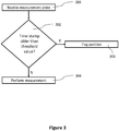
- the measurement process starts with the receipt of a measurement order (step 301). Subsequently, the optical measurement device can check if a current reference value of measurement channel for which the measurement order was received is older than a predetermined threshold value at step 302.
- checking the age of the current reference factor might include comparing the time stamp to the predetermined threshold value directly. If the time stamps indicate a point in time (e.g., a time and or date at which the current reference factor was determined), an age of the current reference factor can be determined by comparing the time stamp and a current system time.
- the particular reference channel can either be flagged (step 303) as unreliable if the current reference factor is too old or the measurement can be performed in the envisaged measurement channel (step 304).
- the predetermined threshold value can be selected to be longer than a measurement time of a biological sample in the respective measurement channel of the optical measurement device (e.g., 1.1 times as long or longer, twice as long or longer or five times as long or longer).
- the age of a reference factor can be used to judge that a particular measurement channel might be defective can be understood in the context of the reference factor update process described in connection with FIG. 2 above.
- the updated reference factors can be discarded as soon as a deviation to a current reference factor is overly large. If there is a persistent error in a particular measurement channel, the updated reference factors will continuously show large deviations to the current reference factor and hence will be discarded. At the same time, the current reference factor will age and eventually reach the predetermined threshold age. On the other hand, if at some point in time the updated reference factor returns to values sufficiently close to the current reference factor, the current reference factor can be replaced by the updated reference factor (which then is "fresh" enough so that it passes the age test in step 302 of FIG. 3 ).
- the optical measurement device can perform one or more measurements on the biological sample.
- the current reference factor of the measurement channel and a detection signal of the reference channel (or one of the reference channels) can be used to correct the detection signal.
- a detection signal of the measurement channel can be weighted by the current reference factor (e.g., multiplied by the current reference factor). In this manner, the inhomogeneity between different measurement channels in an optical measurement device can be leveled.
- a current reference factor of an i-th measurement channel RF i can be 1.1 when a measurement in the particular measurement channel is performed.
- a corrected detection signal e.g., an intensity or a number of counts
- IN i, det refers to a measured detection signal in the respective measurement channel.
- the corrected detection signal e.g., an intensity or a number of counts
- the corrected detection signal is 10% higher than the measured detection signal.
- the corrected detection signal might be, e.g., 5% smaller than the measured detection signal.
- the use of reference factors can level inhomogeneities of the different measurement channels of the optical measurement device and make different detection signals more comparable.
- the detection signal of a measurement channel can also be corrected in additional ways to using a current reference factor of the measurement channel.
- a detection signal of the reference measurement channel measured at the same time as the detection signal of the measurement channel including the biological sample can be used to correct the detection signal. In this manner, drifts during a measurement process (e.g., in a situation where sequential measurements are conducted on a single biological sample) can be corrected.
- the detection signals can be corrected by correction measurement in the respective measurement or reference channel (e.g., a dark measurement in the respective measurement channel) as described above in connection with the determination process of the reference factors. For instance, a dark measurement can be subtracted from the detection signals of the measurement channel and the reference channel.
- the measurement channels are empty.
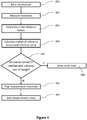
- the optical measurement device can perform a basic initialization. This can involve a predetermined number of self-diagnostic tests to check whether the optical measurement device is functioning properly.
- the optical measurement device can set an operating point for subsequent measurements (e.g., light source parameters, detector parameters and measurement time). In one example, a flat field correction process is performed for all detectors or detector pixels of the optical measurement device.
- the optical measurement device measures detection signals of each measurement channel of the device.
- the measured intensities are then used in step 203 to calculate a set of initial reference factors.
- the same techniques as set out above in connection with FIG. 2 for the reference factor update process can be used.
- the optical measurement device calculates a median of the initial reference factors and a reference value (step 204).
- a median e.g., another average value than the median (e.g., an arithmetic mean) can be calculated.
- the reference value is set to '1'.
- the reference value represents the reference channel.
- the reference value of '1' indicates that an expected detection signal of the reference channel equals an expected signal of the other measurement channels.
- the optical measurement device checks if a deviation of the reference value and the median is out of range (e.g., the reference value deviates by more than a predetermined value from the median of the reference factors). If this is the case, the optical measurement device can enter an error state (step 208).
- the optical measurement device checks if a deviation of the reference factors of each measurement channel and the median is out of range. If this is the case, the respective measurement channel is flagged as unusable (step 206).
- the optical measurement device can enter a measurement mode (step 207).
- the optical measurement device can employ different initialization techniques.
- An alternative initialization technique can involve calculating an average value for the reference factors of all measurement channels of the optical measurement device and, for each measurement channel, determining a deviation of a reference factor of the respective measurement channel and the average reference factor. If the deviation from the reference factor of a measurement channel and the average reference factor exceeds a predetermined limit, generates an error indicator for the respective measurement channel.
- optical measurement devices of the present disclosure can be integrated in different analyzers or analyzer units for biological samples.
- An example system for in-vitro analysis including an integrated optical measurement device according to the present disclosure is depicted in FIG. 5 to FIG. 8 and will be discussed in more detail subsequently.
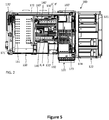
- FIG. 5 to FIG. 8 depict views of a system for in-vitro analysis generally referred to at reference numeral 100.
- FIG. 5 shows an example of a system 100 for in-vitro diagnostic analysis, and in particular a coagulation analyzer.
- the system 100 comprises a reagent holding unit 110 for holding reagents to perform different coagulation tests.
- the reagent unit 110 is embodied as a closed and tempered storage compartment, comprising access holes 111 for a pipetting nozzle to enter the compartment and withdraw an aliquot of reagent.
- the system 100 further comprises a sample rack tray unit 122, which is functionally coupled as a module to the sample loading/unloading unit 120 for loading/unloading sample racks 121 into/from the sample loading/unloading unit 120.
- the system further comprises a central vessel processing area 130'.
- the vessel processing area 130' comprises a first linear static vessel holder 140 and a second linear static vessel holder 140', the static vessel holders 140, 140' each comprising a plurality of vessel placement positions 6, 8, 6', 8' for holding vessels including biological samples (e.g., while the biological samples are incubated, or while optical measurements are performed on the biological samples).
- the vessel processing area 130' further comprises a vessel input station 150 for feeding a vessel at a time to the static vessel holder 140.
- the vessel processing area 130' further comprises first and second movable vessel workstations 160, 161' linearly translatable with respect to the respective static vessel holder 140, 140' and functionally coupled to the respective static vessel holder 140, 140' to transfer vessels between vessel placement positions 6, 8 of the static vessel holder 140.
- the system 100 further comprises two pipette heads 170', 173 translatably mounted on two respective horizontal arms 171, 174 comprising a plurality of pipetting devices each.
- the system 100 further comprises a controller 180' programmed to control the execution of a number of scheduled process operations including operation of the movable vessel workstations 160, 161', of the pipette heads 170', 173 and of the pipetting devices.
- FIG. 6 and FIG. 7 show further views of the example system of FIG. 5 including the components discussed above.
- the system includes two photometric units 142, 142' for performing optical coagulation measurements on biological samples included in vessels 10.
- the photometric units 142, 142' will subsequently be discussed in more detail in connection with FIG. 8 .
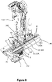
- FIG. 8 shows further details of parts of the example system of FIG. 5 and FIG. 6 .
- only one static vessel holder 140 with the respective movable vessel workstation 160 and only one pipette head 170' are shown for clarity.
- the static vessel holder 140 comprises a plurality of vessel placement positions 6, 8 for placing a plurality of vessels 10.
- the static vessel holder 140 comprises an incubation subunit 140A comprising a plurality of vessel placement positions for incubation 8.
- the static vessel holder 140 further comprises a detection subunit 140B comprising a plurality of vessel placement positions for detection 6 (in this example thirteen).
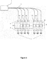
- the detection subunit 140B comprises one the photometric units 142, the photometric unit 142 comprising a light source 1 on one side of the vessel placement positions for detection 6 and an optical detector (not shown) arranged inside the detection subunit 140B on the other side of the vessel placement positions for detection 6.
- the photometric unit 142 comprising a light source 1 on one side of the vessel placement positions for detection 6 and an optical detector (not shown) arranged inside the detection subunit 140B on the other side of the vessel placement positions for detection 6.
- each vessel placement positions for detection 6 there is an optical fiber 2 for guiding light from the light source 1 through a vessel 10 placed in the vessel placement positions for detection 6 and an optical detector placed on the opposite side of the vessel placement positions for detection 6 to detect light passing through the vessel 10 in the vessel placement positions for detection 6.
- each vessel placement positions for detection 6 is arranged in an optical path between an optical fiber 2 and an optical detector.
- the system 100 provides a plurality of measurement channels 3a, 31 (thirteen measurement channels in the example of FIG. 8 , two of which 3a, 31 are shown in FIG. 8 ), where a vessel 10 can be arranged in a respective measurement channel 3a, 31 by placing it in the respective vessel placement positions for detection 6.
- the vessels 10 can therefore conveniently be embodied as cuvettes comprising two parallel and transparent walls, which can be placed in the optical path.
- Light of different wavelengths may be guided through different optical fibers 2 and/or light of different wavelengths may alternately be guided in the same optical fibers 2.
- the light source 1 may be common to all optical fibers 2 and comprises a multi-wavelength light source, e.g. a broad spectrum light source or a plurality of light emitting elements with individual wavelengths or wavelength ranges.
- One of the vessel placement positions for detection 6A is a blank measurement position for taking a blank measurement of each new vessel 10.
- the blank vessel placement positions for detection 6A is the input vessel holding position where a new vessel 10 at a time is placed by the vessel gripper 151 of the vessel input station 150.
- a second vessel placement positions for detection 6" is a reference vessel placement positions for detection as discussed above. This vessel placement positions for detection 6" is part of a reference channel 3a (as also discussed above).
- the vessel input station 150 places a new vessel 10 at a time into the input vessel placement positions for detection 6 of the static vessel holder 140 and/or into a corresponding blank measurement position 6A of the second static vessel holder 140', depending on whether an embodiment with one or two static vessel holders 140, 140' is used.
- a photometric blank measurement of each new vessel 10 in each static vessel holder 140, 140' is then first carried out. After taking a photometric blank measurement of the vessel 10, the respective movable vessel workstations 160, 160' transfer the vessels 10 to a free vessel placement positions for incubation 8, 8' of the respective static vessel holder 140, 140'.
- a particular biological sample and one or more reagents are dispensed into the vessel.
- the vessel 10B held by the gripper 161 is transported to a free vessel placement positions for detection 6, 6' of the detection subunit 140B for detection by using the photometric unit 142 by linearly translating the movable vessel workstation 160.
- the detection by using the photometric unit 142 can include any one of the calibration and/or error detection techniques discussed above.
- reference factors e.g., indicating a ratio of detected intensities in a second measurement channel 31 and a first reference measurement channel 3a
- the system of FIG. 6 to FIG. 8 uses particular photometric units 142, 142'.
- the photometric units 142, 142' can be replaced by any other optical measurement device of the present disclosure.
- the optical measurement device itself can include a computer or computing system performing the signal processing steps of the different techniques for calibration and/or error detection.
- the optical measurement device can be integrated in an analyzer for biological samples (e.g., the analyzer shown in FIG. 5 and FIG. 6 ) and a computer or computing system of the analyser can perform the signal processing steps of the different techniques for calibration and/or error detection.
- the optical measurement device can be communicatively coupled to a computer or computing system (e.g., a remote computer or computing system) performing the signal processing steps of the different techniques for calibration and/or error detection (e.g., through a laboratory communication network).
- a computer or computing system e.g., a remote computer or computing system
- the signal processing steps of the different techniques for calibration and/or error detection e.g., through a laboratory communication network.
- the methods for calibration and/or error detection of the present disclosure can be embodied in instructions on a computer-readable medium which when executed by a computer or computing system can cause the measurement device to carry out the steps of the methods for calibration and/or error detection of the present disclosure.
Claims (15)
- Verfahren zur Kalibrierung und/oder Fehlererkennung in einer optischen Messvorrichtung für biologische Proben mit mindestens einem ersten (3a) und einem zweiten Messkanal (3b, ..., 3n), wobei das Verfahren umfasst:
wiederholtes Durchführen eines Referenzfaktoraktualisierungsprozesses zwischen Messungen von biologischen Proben in dem zweiten Messkanal (3b, ..., 3n) der optischen Messvorrichtung, wobei der Prozess einschließt:Erhalten von einem oder mehreren aktuellen Referenzfaktoren für den zweiten Messkanal (3b, ..., 3n), wobei jeder Referenzfaktor eine Beziehung zwischen zuvor erhaltenen Messsignalen in dem ersten (3a) und zweiten Messkanal (3b, ..., 3n) der optischen Messvorrichtung angibt;Ermitteln (401) eines ersten Erkennungssignals des ersten Messkanals (3a), wobei die biologische Probe nicht eingeschlossen ist;Ermitteln (401) eines zweiten Erkennungssignals des zweiten Messkanals (3b, ..., 3n); Berechnen (402) eines aktualisierten Referenzfaktors für den zweiten Messkanal (3b, ..., 3n) basierend auf dem ersten und zweiten Erkennungssignal;Vergleichen (403) des aktualisierten Referenzfaktors mit mindestens einem von dem einen oder den mehreren aktuellen Referenzfaktoren; undin Abhängigkeit von dem Ergebnis des Vergleichs entweder Speichern (406) des aktualisierten Referenzfaktors als neuen aktuellen Referenzfaktor zur Verwendung in einer späteren Messung in dem zweiten Messkanal (3b, ..., 3n) oder Behalten (404) des einen oder der mehreren aktuellen Referenzfaktoren zur Verwendung in einer späteren Messung in dem zweiten Messkanal (3b, ..., 3n), wobei aktualisierte Referenzfaktoren verworfen werden, die auf dem ersten und zweiten Erkennungssignal basieren, das ermittelt wurde, wenn die biologische Probe in dem zweiten Messkanal (3b, ..., 3n) vorhanden ist. - Verfahren nach Anspruch 1, ferner umfassend:falls der aktualisierte Referenzfaktor um höchstens einen vorbestimmten Wert von dem mindestens einen von dem einen oder den mehreren aktuellen Referenzfaktoren abweicht, Speichern des aktualisierten Referenzfaktors als neuen aktuellen Referenzfaktor zur Verwendung in einer späteren Messung in dem zweiten Messkanal (3n); undfalls der aktualisierte Referenzfaktor um mehr als den vorbestimmten Wert von dem mindestens einen von dem einen oder den mehreren aktuellen Referenzfaktoren abweicht, Behalten des einen oder der mehreren aktuellen Referenzfaktoren zur Verwendung in einer späteren Messung in dem zweiten Messkanal (3n).
- Verfahren nach einem der Ansprüche 1 bis 2, wobei Berechnen des Referenzfaktors Ermitteln eines Verhältnisses von dem ersten und dem zweiten Erkennungssignal einschließt.
- Verfahren nach einem der vorhergehenden Ansprüche, wobei Verwenden des einen oder der mehreren aktuellen Referenzfaktoren in einer späteren Messung in dem zweiten Messkanal (3n) einschließt:Ermitteln eines Erkennungssignals des ersten Messkanals (3a), wobei die biologische Probe nicht eingeschlossen ist;Ermitteln eines Erkennungssignals des zweiten Messkanals (3n) einschließlich einer zu messenden biologischen Probe; undKorrigieren des Erkennungssignals des zweiten Messkanals (3n) durch einen der aktuellen Referenzfaktoren.
- Verfahren nach einem der vorhergehenden Ansprüche, wobei Verwenden des einen oder der mehreren aktuellen Referenzfaktoren in einer späteren Messung in dem zweiten Messkanal einschließt:Ermitteln eines Erkennungssignals des ersten Messkanals, wobei die biologische Probe nicht eingeschlossen ist;Ermitteln eines Erkennungssignals des zweiten Messkanals, wobei eine zu messende biologischen Probe nicht eingeschlossen ist; undKorrigieren des Erkennungssignals des zweiten Messkanals durch einen der aktuellen Referenzfaktoren.
- Verfahren nach Anspruch 4 oder Anspruch 5, wobei Korrigieren des Erkennungssignals Multiplizieren des Erkennungssignals mit dem einen der aktuellen Referenzfaktoren oder Teilen des Erkennungssignals durch den einen der aktuellen Referenzfaktoren einschließt.
- Verfahren nach einem der vorhergehenden Ansprüche, des Weiteren einschließend Speichern eines Zeitstempels für jeden Referenzfaktor, wobei der Zeitstempel angibt, wann der spezielle Referenzfaktor ermittelt worden ist.
- Verfahren nach Anspruch 7, ferner umfassend:Auswerten (302) eines Zeitstempels des aktuellen Referenzfaktors, um ein Alter des aktuellen Referenzfaktors zu ermitteln; undGenerieren (303) einer Fehlermeldung, falls ein Alter des aktuellen Referenzfaktors ein vorbestimmtes Maximalalter überschreitet.
- Verfahren nach einem der Ansprüche 1 bis 8, wobei der Referenzfaktoraktualisierungsprozess von Anspruch 1 kontinuierlich während des Betriebs der optischen Messvorrichtung durchgeführt wird.
- Verfahren nach einem der vorhergehenden Ansprüche, wobei der Referenzfaktoraktualisierungsprozess periodisch durchgeführt wird, wobei der Referenzfaktoraktualisierungsprozess mindestens ein Mal pro Minute oder mindestens ein Mal pro Sekunde durchgeführt wird.
- Verfahren nach einem der vorhergehenden Ansprüche, wobei die optische Messvorrichtung für biologische Proben einen oder mehrere zusätzliche Messkanäle (3b, ..., 3n) einschließt, wobei das Verfahren des Weiteren zwischen den Messungen von biologischen Proben in dem zweiten oder dem einen oder den mehreren zusätzlichen Messkanälen (3b, ..., 3n) der optischen Messvorrichtung wiederholtes Durchführen eines Referenzfaktoraktualisierungsprozesses wie in einem der Ansprüche 1 bis 10 beschrieben für jeden von dem einen oder den mehreren zusätzlichen Messkanälen (3b, ..., 3n) umfasst.
- Verfahren nach einem der vorhergehenden Ansprüche, des Weiteren umfassend:Berechnen (204) eines Durchschnittswerts für die Referenzfaktoren aller Messkanäle (3a, ..., 3n) der optischen Messvorrichtung einschließlich der ersten und zweiten Messkanäle (3a, 3n);für jeden Messkanal (3a, ..., 3n) einschließlich des ersten und des zweiten Messkanals (3a, 3n) Ermitteln einer Abweichung eines Referenzfaktors des jeweiligen Messkanals (3a, ..., 3n) und des durchschnittlichen Referenzfaktors; undfalls die Abweichung von dem Referenzfaktor eines Messkanals (3a, ..., 3n) und des durchschnittlichen Referenzfaktors einen vorbestimmten Grenzwert überschreitet, Markieren des jeweiligen Messkanals (3a, ..., 3n), wobei der Durchschnittswert ein Medianwert oder ein arithmetischer Durchschnittswert ist.
- Verfahren nach einem der vorhergehenden Ansprüche, des Weiteren umfassend: Verzögern der Verwendung des aktualisierten Referenzfaktors in einer späteren Messung in dem zweiten Messkanal (3n), wobei die Verzögerung so gewählt wird, dass die Verwendung von aktualisierten Referenzfaktoren vermieden wird, die während des Einsetzens oder Entfernens eines Gefäßes ermittelt wurden, welches die biologische Probe enthält.
- Computerlesbares Medium mit darauf gespeicherten Anweisungen, die bei Ausführung durch ein Computersystem bewirken, dass die optische Messvorrichtung nach Anspruch 15 die Schritte des Verfahrens gemäß einem der Ansprüche 1 bis 13 durchführt.
- Optische Messvorrichtung für biologische Proben, umfassend:einen ersten Messkanal (3a),einen zweiten Messkanal (3b, ..., 3n),Mittel zum Einsetzen der biologischen Proben in den zweiten Messkanal und Entfernen der biologischen Proben aus dem zweiten Messkanal;einen Detektor (7), der ausgestaltet ist, um Signale von dem ersten (3a) und dem zweiten Messkanal (3b, ..., 3n) zu empfangen; undeine Steuerung, die ausgestaltet ist, um Verfahren zur Kalibrierung und/oder Fehlererkennung in der optischen Messung durchzuführen, wobei das Verfahren umfasst:
wiederholtes Durchführen eines Referenzfaktoraktualisierungsprozesses während des Betriebs der optischen Messvorrichtung, wobei der Prozess die Schritte einschließt:Erhalten von einem oder mehreren aktuellen Referenzfaktoren für den zweiten Messkanal (3b, ..., 3n), wobei jeder Referenzfaktor eine Beziehung zwischen zuvor erhaltenen Messsignalen in dem ersten (3a) und zweiten Messkanal (3b, ..., 3n) der optischen Messvorrichtung angibt;Ermitteln eines ersten Erkennungssignals des ersten Messkanals (3a), wobei die biologische Probe nicht eingeschlossen ist;Ermitteln eines zweiten Erkennungssignals des zweiten Messkanals (3b, ..., 3n);Berechnen eines aktualisierten Referenzfaktors für den zweiten Messkanal (3b, ..., 3n) basierend auf dem ersten und dem zweiten Erkennungssignal; undVergleichen des aktualisierten Referenzfaktors mit mindestens einem von dem einen oder den mehreren aktuellen Referenzfaktoren;in Abhängigkeit von dem Ergebnis des Vergleichs entweder Speichern des aktualisierten Referenzfaktors als neuen aktuellen Referenzfaktor zur Verwendung in einer späteren Messung in dem zweiten Messkanal (3b, ..., 3n) oder Behalten des einen oder der mehreren aktuellen Referenzfaktoren zur Verwendung in einer späteren Messung in dem zweiten Messkanal (3b, ..., 3n), wobei aktualisierte Referenzfaktoren verworfen werden, die auf dem ersten und zweiten Erkennungssignal basieren, das ermittelt wurde, wenn die biologische Probe in dem zweiten Messkanal (3b, ..., 3n) vorhanden ist.
Priority Applications (5)
| Application Number | Priority Date | Filing Date | Title |
|---|---|---|---|
| ES15200769T ES2778677T3 (es) | 2015-12-17 | 2015-12-17 | Calibración y/o detección de errores en un dispositivo de medición óptica para muestras biológicas |
| EP15200769.6A EP3182096B1 (de) | 2015-12-17 | 2015-12-17 | Kalibrierung und/oder fehlererkennung in einer optischen messvorrichtung für biologische proben |
| US15/376,704 US11353471B2 (en) | 2015-12-17 | 2016-12-13 | Calibration and/or error detection in an optical measurement device for biological samples |
| CN201611157483.1A CN106896062B (zh) | 2015-12-17 | 2016-12-15 | 生物样品用的光学测量装置中的校准和/或检错 |
| JP2016242802A JP6799454B2 (ja) | 2015-12-17 | 2016-12-15 | 生物学的試料用の光学測定装置における較正および/またはエラー検出 |
Applications Claiming Priority (1)
| Application Number | Priority Date | Filing Date | Title |
|---|---|---|---|
| EP15200769.6A EP3182096B1 (de) | 2015-12-17 | 2015-12-17 | Kalibrierung und/oder fehlererkennung in einer optischen messvorrichtung für biologische proben |
Publications (2)
| Publication Number | Publication Date |
|---|---|
| EP3182096A1 EP3182096A1 (de) | 2017-06-21 |
| EP3182096B1 true EP3182096B1 (de) | 2020-01-15 |
Family
ID=54979437
Family Applications (1)
| Application Number | Title | Priority Date | Filing Date |
|---|---|---|---|
| EP15200769.6A Active EP3182096B1 (de) | 2015-12-17 | 2015-12-17 | Kalibrierung und/oder fehlererkennung in einer optischen messvorrichtung für biologische proben |
Country Status (5)
| Country | Link |
|---|---|
| US (1) | US11353471B2 (de) |
| EP (1) | EP3182096B1 (de) |
| JP (1) | JP6799454B2 (de) |
| CN (1) | CN106896062B (de) |
| ES (1) | ES2778677T3 (de) |
Families Citing this family (11)
| Publication number | Priority date | Publication date | Assignee | Title |
|---|---|---|---|---|
| EP3314224A4 (de) * | 2015-06-26 | 2019-05-15 | Abbott Laboratories | Bewegliches reaktionsgefässelement zum bewegen von reaktionsgefässen von einer verarbeitungsschiene zu einer rotierenden vorrichtung in einem diagnostischen analysator |
| CN109477789B (zh) * | 2016-07-21 | 2021-10-22 | 西门子医疗保健诊断公司 | 使用比色皿之间的参考测量来消除源灯强度漂移效应 |
| EP3290905B1 (de) * | 2016-09-05 | 2022-10-19 | F. Hoffmann-La Roche AG | Signal-offset-bestimmung und korrektur |
| WO2019044969A1 (ja) * | 2017-09-01 | 2019-03-07 | ウシオ電機株式会社 | マイクロプレートリーダー |
| EP3746755B1 (de) * | 2018-01-30 | 2022-09-28 | GrainSense Oy | Verfahren zur kalibrierung eines integrationshohlraumes |
| CN112041076B (zh) * | 2018-04-23 | 2023-04-18 | 迈恩医疗解决方案有限公司 | 用于从液体介质获得测量信号的自动分析器和光学测量方法 |
| WO2019204840A1 (de) * | 2018-04-23 | 2019-10-31 | Meon Medical Solutions Gmbh & Co Kg | Optische messeinheit und optisches messverfahren zur gewinnung von messsignalen von flüssigen medien |
| EP3614128B1 (de) * | 2018-08-22 | 2023-04-26 | F. Hoffmann-La Roche AG | Verfahren zur korrektur von signallichtintensitäten, die von einem detektor einer detektionseinheit in einem laborinstrument gemessen werden |
| WO2020146741A1 (en) * | 2019-01-10 | 2020-07-16 | Selim Olcum | Calibration of a functional biomarker instrument |
| JP7276462B2 (ja) * | 2019-08-06 | 2023-05-18 | 株式会社島津製作所 | 生化学分析装置及び生化学分析方法 |
| KR102522278B1 (ko) * | 2021-10-29 | 2023-04-17 | 주식회사 신코 | 듀얼 어레이 센서를 이용한 고속 흡광도 측정 마이크로플레이트 리더기 |
Family Cites Families (18)
| Publication number | Priority date | Publication date | Assignee | Title |
|---|---|---|---|---|
| US4591550A (en) | 1984-03-01 | 1986-05-27 | Molecular Devices Corporation | Device having photoresponsive electrode for determining analytes including ligands and antibodies |
| JPS62115348A (ja) * | 1985-09-30 | 1987-05-27 | モレキユラ− デバイスイズ コ−ポレイシヨン | 多ビ−ムによる光度測定装置および測定方法 |
| US7217574B2 (en) * | 2000-10-30 | 2007-05-15 | Sru Biosystems, Inc. | Method and apparatus for biosensor spectral shift detection |
| JP3838501B2 (ja) * | 2001-12-05 | 2006-10-25 | Kddi株式会社 | 光バースト信号ルーチング方式 |
| DE60316985T2 (de) * | 2002-08-28 | 2008-07-24 | Fujifilm Corp. | Messvorrichtung |
| JP4483333B2 (ja) * | 2004-02-17 | 2010-06-16 | 株式会社島津製作所 | 光測定装置における測定方法及びチャンネル間偏差測定用標準器 |
| US7339668B2 (en) | 2005-10-18 | 2008-03-04 | Thermo Electron Scientific Instruments Llc | Spectrometer for analysis of multiple samples |
| CN200950139Y (zh) | 2006-07-19 | 2007-09-19 | 北京工业大学 | 用于生物pcr微通道荧光检测的标准芯片 |
| US7674616B2 (en) * | 2006-09-14 | 2010-03-09 | Hemosense, Inc. | Device and method for measuring properties of a sample |
| JP2009053029A (ja) | 2007-08-27 | 2009-03-12 | Olympus Corp | 自動分析装置 |
| US20110001963A1 (en) * | 2009-07-02 | 2011-01-06 | Durack Gary P | System and method for the measurement of multiple emissions from multiple parallel flow channels in a flow cytometry system |
| US9091637B2 (en) | 2009-12-04 | 2015-07-28 | Duke University | Smart fiber optic sensors systems and methods for quantitative optical spectroscopy |
| WO2012054028A1 (en) * | 2010-10-20 | 2012-04-26 | Analogic Corporation | Method of calibrating and correcting color-bleed factors for color separation in dna analysis |
| WO2013134491A1 (en) | 2012-03-09 | 2013-09-12 | Siemens Healthcare Diagnostics Inc. | Calibration method for reagent card analyzers |
| GB2506375B (en) * | 2012-09-27 | 2017-10-18 | Epistem Ltd | Data processing and analysis systems |
| CN103528952B (zh) | 2013-10-25 | 2016-07-06 | 中国科学院合肥物质科学研究院 | 一种开放光路式气体分析仪通量校正测量装置及测量方法 |
| US20150369656A1 (en) * | 2013-12-19 | 2015-12-24 | Halliburton Energy Services, Inc. | Cross-Sensor Standardization |
| CN104198382A (zh) | 2014-06-18 | 2014-12-10 | 上海理工大学 | 基于检测农药残留的双通道检测装置及方法 |
-
2015
- 2015-12-17 ES ES15200769T patent/ES2778677T3/es active Active
- 2015-12-17 EP EP15200769.6A patent/EP3182096B1/de active Active
-
2016
- 2016-12-13 US US15/376,704 patent/US11353471B2/en active Active
- 2016-12-15 CN CN201611157483.1A patent/CN106896062B/zh active Active
- 2016-12-15 JP JP2016242802A patent/JP6799454B2/ja active Active
Non-Patent Citations (1)
| Title |
|---|
| None * |
Also Published As
| Publication number | Publication date |
|---|---|
| CN106896062B (zh) | 2020-11-06 |
| ES2778677T3 (es) | 2020-08-11 |
| JP6799454B2 (ja) | 2020-12-16 |
| EP3182096A1 (de) | 2017-06-21 |
| CN106896062A (zh) | 2017-06-27 |
| JP2017111145A (ja) | 2017-06-22 |
| US11353471B2 (en) | 2022-06-07 |
| US20170176478A1 (en) | 2017-06-22 |
Similar Documents
| Publication | Publication Date | Title |
|---|---|---|
| EP3182096B1 (de) | Kalibrierung und/oder fehlererkennung in einer optischen messvorrichtung für biologische proben | |
| EP1887356B1 (de) | Automatisches Analysegerät | |
| EP2428802B1 (de) | Automatische analysevorrichtung und analyseverfahren dafür | |
| EP1840559B1 (de) | Blutanalysegerät und Blutanalyseverfahren | |
| EP2813839A1 (de) | Kalibrierverfahren für Fotometrie | |
| CN101452005A (zh) | 自动分析装置 | |
| JP2015510131A (ja) | 試薬カード分析器の較正方法 | |
| EP2584342B1 (de) | Verfahren für quantitative optische Messungen und Laborvorrichtung | |
| US10856391B2 (en) | Method to correct signal light intensities measured by a detector of a detection unit in a laboratory instrument | |
| EP3373004B1 (de) | Verfahren zur bestimmung einer analytkonzentrationen | |
| CN114550826A (zh) | 一种实时荧光定量pcr的数据分析系统及其方法 | |
| US10458997B2 (en) | Signal offset determination and correction | |
| WO2014119435A1 (ja) | 自動分析装置 | |
| EP3730930B1 (de) | Signalverarbeitungsvorrichtung und signalverarbeitungsverfahren | |
| JP2005127757A (ja) | 自動分析装置 | |
| JP7300826B2 (ja) | 分析装置及び分析方法 | |
| US20080206100A1 (en) | Automatic analyzer | |
| US20240003923A1 (en) | Calibration and validation of cuvettes in automated chemical analyzers |
Legal Events
| Date | Code | Title | Description |
|---|---|---|---|
| PUAI | Public reference made under article 153(3) epc to a published international application that has entered the european phase |
Free format text: ORIGINAL CODE: 0009012 |
|
| STAA | Information on the status of an ep patent application or granted ep patent |
Free format text: STATUS: THE APPLICATION HAS BEEN PUBLISHED |
|
| AK | Designated contracting states |
Kind code of ref document: A1 Designated state(s): AL AT BE BG CH CY CZ DE DK EE ES FI FR GB GR HR HU IE IS IT LI LT LU LV MC MK MT NL NO PL PT RO RS SE SI SK SM TR |
|
| AX | Request for extension of the european patent |
Extension state: BA ME |
|
| STAA | Information on the status of an ep patent application or granted ep patent |
Free format text: STATUS: REQUEST FOR EXAMINATION WAS MADE |
|
| 17P | Request for examination filed |
Effective date: 20171212 |
|
| RBV | Designated contracting states (corrected) |
Designated state(s): AL AT BE BG CH CY CZ DE DK EE ES FI FR GB GR HR HU IE IS IT LI LT LU LV MC MK MT NL NO PL PT RO RS SE SI SK SM TR |
|
| STAA | Information on the status of an ep patent application or granted ep patent |
Free format text: STATUS: EXAMINATION IS IN PROGRESS |
|
| 17Q | First examination report despatched |
Effective date: 20181129 |
|
| GRAP | Despatch of communication of intention to grant a patent |
Free format text: ORIGINAL CODE: EPIDOSNIGR1 |
|
| STAA | Information on the status of an ep patent application or granted ep patent |
Free format text: STATUS: GRANT OF PATENT IS INTENDED |
|
| INTG | Intention to grant announced |
Effective date: 20190809 |
|
| GRAS | Grant fee paid |
Free format text: ORIGINAL CODE: EPIDOSNIGR3 |
|
| GRAA | (expected) grant |
Free format text: ORIGINAL CODE: 0009210 |
|
| STAA | Information on the status of an ep patent application or granted ep patent |
Free format text: STATUS: THE PATENT HAS BEEN GRANTED |
|
| AK | Designated contracting states |
Kind code of ref document: B1 Designated state(s): AL AT BE BG CH CY CZ DE DK EE ES FI FR GB GR HR HU IE IS IT LI LT LU LV MC MK MT NL NO PL PT RO RS SE SI SK SM TR |
|
| REG | Reference to a national code |
Ref country code: GB Ref legal event code: FG4D Ref country code: CH Ref legal event code: EP |
|
| REG | Reference to a national code |
Ref country code: IE Ref legal event code: FG4D |
|
| REG | Reference to a national code |
Ref country code: DE Ref legal event code: R096 Ref document number: 602015045543 Country of ref document: DE |
|
| REG | Reference to a national code |
Ref country code: AT Ref legal event code: REF Ref document number: 1225570 Country of ref document: AT Kind code of ref document: T Effective date: 20200215 |
|
| REG | Reference to a national code |
Ref country code: NL Ref legal event code: MP Effective date: 20200115 |
|
| REG | Reference to a national code |
Ref country code: LT Ref legal event code: MG4D |
|
| PG25 | Lapsed in a contracting state [announced via postgrant information from national office to epo] |
Ref country code: RS Free format text: LAPSE BECAUSE OF FAILURE TO SUBMIT A TRANSLATION OF THE DESCRIPTION OR TO PAY THE FEE WITHIN THE PRESCRIBED TIME-LIMIT Effective date: 20200115 Ref country code: NL Free format text: LAPSE BECAUSE OF FAILURE TO SUBMIT A TRANSLATION OF THE DESCRIPTION OR TO PAY THE FEE WITHIN THE PRESCRIBED TIME-LIMIT Effective date: 20200115 Ref country code: FI Free format text: LAPSE BECAUSE OF FAILURE TO SUBMIT A TRANSLATION OF THE DESCRIPTION OR TO PAY THE FEE WITHIN THE PRESCRIBED TIME-LIMIT Effective date: 20200115 Ref country code: NO Free format text: LAPSE BECAUSE OF FAILURE TO SUBMIT A TRANSLATION OF THE DESCRIPTION OR TO PAY THE FEE WITHIN THE PRESCRIBED TIME-LIMIT Effective date: 20200415 Ref country code: PT Free format text: LAPSE BECAUSE OF FAILURE TO SUBMIT A TRANSLATION OF THE DESCRIPTION OR TO PAY THE FEE WITHIN THE PRESCRIBED TIME-LIMIT Effective date: 20200607 |
|
| REG | Reference to a national code |
Ref country code: ES Ref legal event code: FG2A Ref document number: 2778677 Country of ref document: ES Kind code of ref document: T3 Effective date: 20200811 |
|
| PG25 | Lapsed in a contracting state [announced via postgrant information from national office to epo] |
Ref country code: IS Free format text: LAPSE BECAUSE OF FAILURE TO SUBMIT A TRANSLATION OF THE DESCRIPTION OR TO PAY THE FEE WITHIN THE PRESCRIBED TIME-LIMIT Effective date: 20200515 Ref country code: BG Free format text: LAPSE BECAUSE OF FAILURE TO SUBMIT A TRANSLATION OF THE DESCRIPTION OR TO PAY THE FEE WITHIN THE PRESCRIBED TIME-LIMIT Effective date: 20200415 Ref country code: SE Free format text: LAPSE BECAUSE OF FAILURE TO SUBMIT A TRANSLATION OF THE DESCRIPTION OR TO PAY THE FEE WITHIN THE PRESCRIBED TIME-LIMIT Effective date: 20200115 Ref country code: LV Free format text: LAPSE BECAUSE OF FAILURE TO SUBMIT A TRANSLATION OF THE DESCRIPTION OR TO PAY THE FEE WITHIN THE PRESCRIBED TIME-LIMIT Effective date: 20200115 Ref country code: HR Free format text: LAPSE BECAUSE OF FAILURE TO SUBMIT A TRANSLATION OF THE DESCRIPTION OR TO PAY THE FEE WITHIN THE PRESCRIBED TIME-LIMIT Effective date: 20200115 Ref country code: GR Free format text: LAPSE BECAUSE OF FAILURE TO SUBMIT A TRANSLATION OF THE DESCRIPTION OR TO PAY THE FEE WITHIN THE PRESCRIBED TIME-LIMIT Effective date: 20200416 |
|
| REG | Reference to a national code |
Ref country code: DE Ref legal event code: R097 Ref document number: 602015045543 Country of ref document: DE |
|
| PG25 | Lapsed in a contracting state [announced via postgrant information from national office to epo] |
Ref country code: SK Free format text: LAPSE BECAUSE OF FAILURE TO SUBMIT A TRANSLATION OF THE DESCRIPTION OR TO PAY THE FEE WITHIN THE PRESCRIBED TIME-LIMIT Effective date: 20200115 Ref country code: DK Free format text: LAPSE BECAUSE OF FAILURE TO SUBMIT A TRANSLATION OF THE DESCRIPTION OR TO PAY THE FEE WITHIN THE PRESCRIBED TIME-LIMIT Effective date: 20200115 Ref country code: LT Free format text: LAPSE BECAUSE OF FAILURE TO SUBMIT A TRANSLATION OF THE DESCRIPTION OR TO PAY THE FEE WITHIN THE PRESCRIBED TIME-LIMIT Effective date: 20200115 Ref country code: EE Free format text: LAPSE BECAUSE OF FAILURE TO SUBMIT A TRANSLATION OF THE DESCRIPTION OR TO PAY THE FEE WITHIN THE PRESCRIBED TIME-LIMIT Effective date: 20200115 Ref country code: SM Free format text: LAPSE BECAUSE OF FAILURE TO SUBMIT A TRANSLATION OF THE DESCRIPTION OR TO PAY THE FEE WITHIN THE PRESCRIBED TIME-LIMIT Effective date: 20200115 Ref country code: CZ Free format text: LAPSE BECAUSE OF FAILURE TO SUBMIT A TRANSLATION OF THE DESCRIPTION OR TO PAY THE FEE WITHIN THE PRESCRIBED TIME-LIMIT Effective date: 20200115 Ref country code: RO Free format text: LAPSE BECAUSE OF FAILURE TO SUBMIT A TRANSLATION OF THE DESCRIPTION OR TO PAY THE FEE WITHIN THE PRESCRIBED TIME-LIMIT Effective date: 20200115 |
|
| REG | Reference to a national code |
Ref country code: AT Ref legal event code: MK05 Ref document number: 1225570 Country of ref document: AT Kind code of ref document: T Effective date: 20200115 |
|
| PLBE | No opposition filed within time limit |
Free format text: ORIGINAL CODE: 0009261 |
|
| STAA | Information on the status of an ep patent application or granted ep patent |
Free format text: STATUS: NO OPPOSITION FILED WITHIN TIME LIMIT |
|
| 26N | No opposition filed |
Effective date: 20201016 |
|
| PG25 | Lapsed in a contracting state [announced via postgrant information from national office to epo] |
Ref country code: AT Free format text: LAPSE BECAUSE OF FAILURE TO SUBMIT A TRANSLATION OF THE DESCRIPTION OR TO PAY THE FEE WITHIN THE PRESCRIBED TIME-LIMIT Effective date: 20200115 |
|
| PG25 | Lapsed in a contracting state [announced via postgrant information from national office to epo] |
Ref country code: SI Free format text: LAPSE BECAUSE OF FAILURE TO SUBMIT A TRANSLATION OF THE DESCRIPTION OR TO PAY THE FEE WITHIN THE PRESCRIBED TIME-LIMIT Effective date: 20200115 Ref country code: PL Free format text: LAPSE BECAUSE OF FAILURE TO SUBMIT A TRANSLATION OF THE DESCRIPTION OR TO PAY THE FEE WITHIN THE PRESCRIBED TIME-LIMIT Effective date: 20200115 |
|
| PG25 | Lapsed in a contracting state [announced via postgrant information from national office to epo] |
Ref country code: MC Free format text: LAPSE BECAUSE OF FAILURE TO SUBMIT A TRANSLATION OF THE DESCRIPTION OR TO PAY THE FEE WITHIN THE PRESCRIBED TIME-LIMIT Effective date: 20200115 |
|
| REG | Reference to a national code |
Ref country code: BE Ref legal event code: MM Effective date: 20201231 |
|
| PG25 | Lapsed in a contracting state [announced via postgrant information from national office to epo] |
Ref country code: LU Free format text: LAPSE BECAUSE OF NON-PAYMENT OF DUE FEES Effective date: 20201217 Ref country code: IE Free format text: LAPSE BECAUSE OF NON-PAYMENT OF DUE FEES Effective date: 20201217 |
|
| PG25 | Lapsed in a contracting state [announced via postgrant information from national office to epo] |
Ref country code: TR Free format text: LAPSE BECAUSE OF FAILURE TO SUBMIT A TRANSLATION OF THE DESCRIPTION OR TO PAY THE FEE WITHIN THE PRESCRIBED TIME-LIMIT Effective date: 20200115 Ref country code: MT Free format text: LAPSE BECAUSE OF FAILURE TO SUBMIT A TRANSLATION OF THE DESCRIPTION OR TO PAY THE FEE WITHIN THE PRESCRIBED TIME-LIMIT Effective date: 20200115 Ref country code: CY Free format text: LAPSE BECAUSE OF FAILURE TO SUBMIT A TRANSLATION OF THE DESCRIPTION OR TO PAY THE FEE WITHIN THE PRESCRIBED TIME-LIMIT Effective date: 20200115 |
|
| PG25 | Lapsed in a contracting state [announced via postgrant information from national office to epo] |
Ref country code: MK Free format text: LAPSE BECAUSE OF FAILURE TO SUBMIT A TRANSLATION OF THE DESCRIPTION OR TO PAY THE FEE WITHIN THE PRESCRIBED TIME-LIMIT Effective date: 20200115 Ref country code: AL Free format text: LAPSE BECAUSE OF FAILURE TO SUBMIT A TRANSLATION OF THE DESCRIPTION OR TO PAY THE FEE WITHIN THE PRESCRIBED TIME-LIMIT Effective date: 20200115 |
|
| PG25 | Lapsed in a contracting state [announced via postgrant information from national office to epo] |
Ref country code: BE Free format text: LAPSE BECAUSE OF NON-PAYMENT OF DUE FEES Effective date: 20201231 |
|
| PGFP | Annual fee paid to national office [announced via postgrant information from national office to epo] |
Ref country code: ES Payment date: 20230109 Year of fee payment: 8 Ref country code: CH Payment date: 20230101 Year of fee payment: 8 |
|
| PGFP | Annual fee paid to national office [announced via postgrant information from national office to epo] |
Ref country code: IT Payment date: 20221220 Year of fee payment: 8 |
|
| PGFP | Annual fee paid to national office [announced via postgrant information from national office to epo] |
Ref country code: GB Payment date: 20231121 Year of fee payment: 9 |
|
| PGFP | Annual fee paid to national office [announced via postgrant information from national office to epo] |
Ref country code: FR Payment date: 20231122 Year of fee payment: 9 Ref country code: DE Payment date: 20231121 Year of fee payment: 9 |
|
| PGFP | Annual fee paid to national office [announced via postgrant information from national office to epo] |
Ref country code: ES Payment date: 20240102 Year of fee payment: 9 |
|
| PGFP | Annual fee paid to national office [announced via postgrant information from national office to epo] |
Ref country code: CH Payment date: 20240101 Year of fee payment: 9 |