EP3181191B1 - Appareil de détection de pression respiratoire dans un système de stimulation implantable - Google Patents
Appareil de détection de pression respiratoire dans un système de stimulation implantable Download PDFInfo
- Publication number
- EP3181191B1 EP3181191B1 EP16192561.5A EP16192561A EP3181191B1 EP 3181191 B1 EP3181191 B1 EP 3181191B1 EP 16192561 A EP16192561 A EP 16192561A EP 3181191 B1 EP3181191 B1 EP 3181191B1
- Authority
- EP
- European Patent Office
- Prior art keywords
- sensor
- lead
- anchor
- pressure
- lead body
- Prior art date
- Legal status (The legal status is an assumption and is not a legal conclusion. Google has not performed a legal analysis and makes no representation as to the accuracy of the status listed.)
- Active
Links
- 230000000241 respiratory effect Effects 0.000 title claims description 54
- 230000000638 stimulation Effects 0.000 title description 29
- 210000001519 tissue Anatomy 0.000 claims description 24
- 230000003601 intercostal effect Effects 0.000 claims description 16
- 210000003205 muscle Anatomy 0.000 claims description 11
- 238000007920 subcutaneous administration Methods 0.000 claims description 9
- 210000002808 connective tissue Anatomy 0.000 claims description 5
- 210000004224 pleura Anatomy 0.000 description 17
- 208000001797 obstructive sleep apnea Diseases 0.000 description 16
- 230000007246 mechanism Effects 0.000 description 14
- 230000029058 respiratory gaseous exchange Effects 0.000 description 14
- 238000002560 therapeutic procedure Methods 0.000 description 14
- 238000010586 diagram Methods 0.000 description 13
- 210000004072 lung Anatomy 0.000 description 12
- 238000000034 method Methods 0.000 description 12
- 230000003434 inspiratory effect Effects 0.000 description 10
- 210000004379 membrane Anatomy 0.000 description 8
- 239000012528 membrane Substances 0.000 description 8
- 201000002859 sleep apnea Diseases 0.000 description 8
- 230000000694 effects Effects 0.000 description 6
- 238000001914 filtration Methods 0.000 description 6
- 238000002513 implantation Methods 0.000 description 6
- 230000033001 locomotion Effects 0.000 description 6
- 230000000747 cardiac effect Effects 0.000 description 5
- 210000000038 chest Anatomy 0.000 description 5
- 230000006870 function Effects 0.000 description 5
- 238000012544 monitoring process Methods 0.000 description 5
- 210000002445 nipple Anatomy 0.000 description 5
- 238000011282 treatment Methods 0.000 description 5
- 210000001169 hypoglossal nerve Anatomy 0.000 description 4
- 210000001664 manubrium Anatomy 0.000 description 4
- 210000005036 nerve Anatomy 0.000 description 4
- 230000000414 obstructive effect Effects 0.000 description 4
- 210000003281 pleural cavity Anatomy 0.000 description 4
- 230000002277 temperature effect Effects 0.000 description 4
- 230000007704 transition Effects 0.000 description 4
- WABPQHHGFIMREM-NOHWODKXSA-N lead-200 Chemical compound [200Pb] WABPQHHGFIMREM-NOHWODKXSA-N 0.000 description 3
- 210000000115 thoracic cavity Anatomy 0.000 description 3
- 208000036829 Device dislocation Diseases 0.000 description 2
- 239000000654 additive Substances 0.000 description 2
- 230000000996 additive effect Effects 0.000 description 2
- 208000008784 apnea Diseases 0.000 description 2
- 238000013459 approach Methods 0.000 description 2
- 210000000988 bone and bone Anatomy 0.000 description 2
- 210000000845 cartilage Anatomy 0.000 description 2
- 238000004891 communication Methods 0.000 description 2
- 230000008867 communication pathway Effects 0.000 description 2
- 238000001816 cooling Methods 0.000 description 2
- 230000000875 corresponding effect Effects 0.000 description 2
- QTCANKDTWWSCMR-UHFFFAOYSA-N costic aldehyde Natural products C1CCC(=C)C2CC(C(=C)C=O)CCC21C QTCANKDTWWSCMR-UHFFFAOYSA-N 0.000 description 2
- 239000013078 crystal Substances 0.000 description 2
- 210000003238 esophagus Anatomy 0.000 description 2
- ISTFUJWTQAMRGA-UHFFFAOYSA-N iso-beta-costal Natural products C1C(C(=C)C=O)CCC2(C)CCCC(C)=C21 ISTFUJWTQAMRGA-UHFFFAOYSA-N 0.000 description 2
- 238000005259 measurement Methods 0.000 description 2
- 230000008569 process Effects 0.000 description 2
- 238000012545 processing Methods 0.000 description 2
- 230000001902 propagating effect Effects 0.000 description 2
- 230000009467 reduction Effects 0.000 description 2
- 230000004044 response Effects 0.000 description 2
- 230000001225 therapeutic effect Effects 0.000 description 2
- 210000003437 trachea Anatomy 0.000 description 2
- 239000000853 adhesive Substances 0.000 description 1
- 230000001070 adhesive effect Effects 0.000 description 1
- 210000003484 anatomy Anatomy 0.000 description 1
- 238000004873 anchoring Methods 0.000 description 1
- 230000006399 behavior Effects 0.000 description 1
- 230000008901 benefit Effects 0.000 description 1
- 230000005540 biological transmission Effects 0.000 description 1
- 239000008280 blood Substances 0.000 description 1
- 210000004369 blood Anatomy 0.000 description 1
- 230000017531 blood circulation Effects 0.000 description 1
- 230000008859 change Effects 0.000 description 1
- 239000004020 conductor Substances 0.000 description 1
- 230000002596 correlated effect Effects 0.000 description 1
- 230000008878 coupling Effects 0.000 description 1
- 238000010168 coupling process Methods 0.000 description 1
- 238000005859 coupling reaction Methods 0.000 description 1
- 238000003618 dip coating Methods 0.000 description 1
- 238000010292 electrical insulation Methods 0.000 description 1
- 210000003195 fascia Anatomy 0.000 description 1
- 238000002594 fluoroscopy Methods 0.000 description 1
- 230000004217 heart function Effects 0.000 description 1
- 239000007943 implant Substances 0.000 description 1
- 239000003550 marker Substances 0.000 description 1
- 239000000463 material Substances 0.000 description 1
- 230000005012 migration Effects 0.000 description 1
- 238000013508 migration Methods 0.000 description 1
- 238000002324 minimally invasive surgery Methods 0.000 description 1
- 210000000944 nerve tissue Anatomy 0.000 description 1
- 238000006213 oxygenation reaction Methods 0.000 description 1
- 210000002976 pectoralis muscle Anatomy 0.000 description 1
- 230000000149 penetrating effect Effects 0.000 description 1
- 210000000578 peripheral nerve Anatomy 0.000 description 1
- 230000002685 pulmonary effect Effects 0.000 description 1
- 230000003252 repetitive effect Effects 0.000 description 1
- 239000012858 resilient material Substances 0.000 description 1
- 230000004202 respiratory function Effects 0.000 description 1
- 230000035945 sensitivity Effects 0.000 description 1
- 210000004872 soft tissue Anatomy 0.000 description 1
- 210000001562 sternum Anatomy 0.000 description 1
- 230000004936 stimulating effect Effects 0.000 description 1
- 230000001360 synchronised effect Effects 0.000 description 1
- 238000011269 treatment regimen Methods 0.000 description 1
- 230000005641 tunneling Effects 0.000 description 1
- 238000007794 visualization technique Methods 0.000 description 1
- 238000010792 warming Methods 0.000 description 1
Images


Classifications
-
- A—HUMAN NECESSITIES
- A61—MEDICAL OR VETERINARY SCIENCE; HYGIENE
- A61B—DIAGNOSIS; SURGERY; IDENTIFICATION
- A61B5/00—Measuring for diagnostic purposes; Identification of persons
- A61B5/03—Detecting, measuring or recording fluid pressure within the body other than blood pressure, e.g. cerebral pressure; Measuring pressure in body tissues or organs
-
- A—HUMAN NECESSITIES
- A61—MEDICAL OR VETERINARY SCIENCE; HYGIENE
- A61B—DIAGNOSIS; SURGERY; IDENTIFICATION
- A61B5/00—Measuring for diagnostic purposes; Identification of persons
- A61B5/01—Measuring temperature of body parts ; Diagnostic temperature sensing, e.g. for malignant or inflamed tissue
-
- A—HUMAN NECESSITIES
- A61—MEDICAL OR VETERINARY SCIENCE; HYGIENE
- A61B—DIAGNOSIS; SURGERY; IDENTIFICATION
- A61B5/00—Measuring for diagnostic purposes; Identification of persons
- A61B5/08—Detecting, measuring or recording devices for evaluating the respiratory organs
- A61B5/0826—Detecting or evaluating apnoea events
-
- A—HUMAN NECESSITIES
- A61—MEDICAL OR VETERINARY SCIENCE; HYGIENE
- A61B—DIAGNOSIS; SURGERY; IDENTIFICATION
- A61B5/00—Measuring for diagnostic purposes; Identification of persons
- A61B5/48—Other medical applications
- A61B5/4806—Sleep evaluation
- A61B5/4818—Sleep apnoea
-
- A—HUMAN NECESSITIES
- A61—MEDICAL OR VETERINARY SCIENCE; HYGIENE
- A61N—ELECTROTHERAPY; MAGNETOTHERAPY; RADIATION THERAPY; ULTRASOUND THERAPY
- A61N1/00—Electrotherapy; Circuits therefor
- A61N1/18—Applying electric currents by contact electrodes
- A61N1/32—Applying electric currents by contact electrodes alternating or intermittent currents
- A61N1/36—Applying electric currents by contact electrodes alternating or intermittent currents for stimulation
- A61N1/3601—Applying electric currents by contact electrodes alternating or intermittent currents for stimulation of respiratory organs
-
- A—HUMAN NECESSITIES
- A61—MEDICAL OR VETERINARY SCIENCE; HYGIENE
- A61N—ELECTROTHERAPY; MAGNETOTHERAPY; RADIATION THERAPY; ULTRASOUND THERAPY
- A61N1/00—Electrotherapy; Circuits therefor
- A61N1/18—Applying electric currents by contact electrodes
- A61N1/32—Applying electric currents by contact electrodes alternating or intermittent currents
- A61N1/36—Applying electric currents by contact electrodes alternating or intermittent currents for stimulation
- A61N1/3605—Implantable neurostimulators for stimulating central or peripheral nerve system
- A61N1/36128—Control systems
- A61N1/36135—Control systems using physiological parameters
-
- A—HUMAN NECESSITIES
- A61—MEDICAL OR VETERINARY SCIENCE; HYGIENE
- A61N—ELECTROTHERAPY; MAGNETOTHERAPY; RADIATION THERAPY; ULTRASOUND THERAPY
- A61N1/00—Electrotherapy; Circuits therefor
- A61N1/18—Applying electric currents by contact electrodes
- A61N1/32—Applying electric currents by contact electrodes alternating or intermittent currents
- A61N1/36—Applying electric currents by contact electrodes alternating or intermittent currents for stimulation
- A61N1/362—Heart stimulators
- A61N1/365—Heart stimulators controlled by a physiological parameter, e.g. heart potential
- A61N1/36514—Heart stimulators controlled by a physiological parameter, e.g. heart potential controlled by a physiological quantity other than heart potential, e.g. blood pressure
- A61N1/36521—Heart stimulators controlled by a physiological parameter, e.g. heart potential controlled by a physiological quantity other than heart potential, e.g. blood pressure the parameter being derived from measurement of an electrical impedance
Definitions
- the invention relates generally to an implantable stimulation system for stimulating and monitoring soft tissue in a patient, and more particularly, for sensing respiratory pressure to control delivery of therapy to nerve tissue.
- Sleep apnea generally refers to the cessation of breathing during sleep.
- One type of sleep apnea referred to as obstructive sleep apnea (OSA)
- OSA obstructive sleep apnea
- One treatment for obstructive sleep apnea has included the delivery of electrical stimulation to the hypoglossal nerve, located in the neck region under the chin.
- Such stimulation therapy activates the upper airway muscles to maintain upper airway patency.
- increased respiratory effort resulting from the difficulty in breathing through an obstructed airway is avoided by synchronized stimulation of an upper airway muscle or muscle group that holds the airway open during the inspiratory phase of breathing.
- the genioglossus muscle is stimulated during treatment of sleep apnea by a cuff electrode place around the hypoglossal nerve.
- obstructive sleep apnea treatment may include the use of a sensor that is surgically implanted in a region that has pressure continuity with the intrapleural space, such as the suprasternal notch, the space between the trachea and esophagus, or by being attached to either of the trachea or esophagus.
- the sensor may also be positioned intercostally, or secured in a position for sensing pressure at the posterior side of the manubrium.
- the suprasternal notch and manubrium of the sternum are well known structures on the upper chest that are in anatomical continuity with the intrapleural space. Changes in intrapleural pressure provide a characteristic respiratory effort waveform, and therefore the sensor enables respiratory effort waveform information to be utilized to determine increased respiratory effort, which is then used to control delivery of therapy in response to determined increases in respiratory effort.
- the location for placement of the sensor is, at least in part, chosen as a function of a delay, i.e. the propagation time associated with a pressure waveform characteristic of respiratory effort propagating from the respiratory point of origin to the sensor position.
- the chosen location is also a function of the amount of filtering necessary to achieve a usable sensed signal at a particular location, i.e. the amount of filtering that is used to remove waveforms other than the waveform associated with the desired sensed characteristic, such as the filtering required to remove cardiac waveform activity, for example.
- the sensed signal tends to be corrupted by an added signal artifacts caused by cardiac vessels because of the close proximity of cardiac vessels to the sensor.
- implanting the sensor using the known placement positions tends to be an invasive procedure.
- an implantable sensing device includes a sensing element and a mounting element.
- the mounting element has a first end and a second end with a longitudinal axis therethrough.
- the sensing element is positioned at the first end of the mounting element with the mounting element having a length that is adjustable along the longitudinal axis.
- the mounting element includes a sleeve having a first open end and a second open end with the longitudinal axis therethrough.
- the sensing element is positioned in the second open end and includes a lead body connected thereto extending through the second open end.
- the sleeve includes an outer sleeve member coupled for adjustment along the longitudinal axis with respect to an inner sleeve member.
- the mounting element may include a flexible element about the first open end extending outwardly relative to the longitudinal axis and a flange element extending outwardly relative to the longitudinal axis from at least a portion of the second end.
- the device can be implanted in a bone with the flange element and the flexible element for direct or indirect contact with the anterior and posterior surface of the bone.
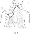
- FIG. 1 is a schematic diagram of an implantable stimulation system, according to an embodiment of the present disclosure.
- an example of an implantable stimulation system 10 includes an implantable pulse generator (IPG) 55, capable of being surgically positioned within a pectoral region of a patient 20, and a stimulation lead 52 electrically coupled with the IPG 55 via a connector (not shown) positioned within a connection port of the IPG 55.
- the lead 52 includes an electrode or electrode system 65 and extends from the IPG 55 so that the electrode system 65 is positioned in proximity to a desired nerve, such as the hypoglossal nerve 53 of the patient 20, to enable stimulation of the nerve 53, as described below in detail.
- an implantable stimulation system in which lead 52 may be utilized for example, is described in U.S. Patent No. 6,572,543 .
- a sensor lead 57 is electrically coupled to the IPG 55 and extends from the IPG 55 so that a sensor or transducer 60 can be positioned in the patient 20 for sensing of respiratory effort.
- respiratory sensing embodiments described herein can be used with other implantable stimulation systems for treating sleep apnea.
- system 10 also comprises additional sensors to obtain further physiologic data associated with respiratory functions, such as various sensors distributed about the chest area for measuring a trans-thoracic bio-impedance signal, an electrocardiogram (ECG) signal, or other respiratory-associated signals.
- additional sensors to obtain further physiologic data associated with respiratory functions, such as various sensors distributed about the chest area for measuring a trans-thoracic bio-impedance signal, an electrocardiogram (ECG) signal, or other respiratory-associated signals.
- ECG electrocardiogram
- the sensing and stimulation system for treating obstructive sleep apnea is a totally implantable system which provides therapeutic solutions for patients diagnosed with obstructive sleep apnea.
- one or more components of the system are not implanted in a body of the patient.
- Such non-implanted components include external sensors (e.g., impedance, heart rate, etc.), an external processing unit, or an external power source.
- the implanted portion(s) of the system provides a communication pathway to enable transmission of data and/or controls signals both to and from the implanted portions of the system relative to the external portions of the system.
- the communication pathway includes a radiofrequency (RF) telemetry link or other wireless communication protocols.
- RF radiofrequency
- the system is designed to stimulate the hypoglossal nerve during inspiration to thereby prevent obstructions or occlusions in the upper airway during sleep.
- the implantable system comprises an implantable pulse generator (IPG), a peripheral nerve cuff stimulation lead, and a respiratory sensing lead.
- IPG implantable pulse generator
- the senor 60 is a respiratory pressure sensor that is surgically implanted in a region that has pressure continuity with the pleura via an intrapleural placement or an extrapleural placement (including but not limited to an intercostal placement), as will be further described in association with Figure 2 .
- the location for placement of the sensor 60 is, at least in part, chosen as a function of a delay, i.e. the propagation time associated with a pressure waveform characteristic of respiratory effort propagating from the respiratory point of origin to the sensor position.
- the chosen location is also a function of the amount of filtering or signal processing necessary to achieve a usable sensed signal at a particular location, i.e.
- the positioning of the sensor 60 enables the IPG 55 to receive respiratory effort waveform information and to use this information to control delivery of the therapy.
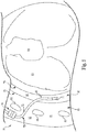
- an implantable stimulation system 10 comprises a sensing system 70 including a lead 75 configured to place a respiratory pressure sensor 71 within an intrapleural space 90 so that sensor 71 is positioned in close proximity to the lung 80.
- the sensor 71 becomes directly coupled relative to the respiratory pressures at the pleura.
- the intrapleural space 90 includes the cavity between the parietal pleura 78 and a pulmonary pleura 79.
- lead 75 includes a lead body 72 that supports sensor 71 at its distal end and an anchor 74 (such as a wing-like fixation member) located at a more proximal portion of lead body 72.
- the anchor 74 ensures that sensor 71 remains positioned to orient the membrane portion of the sensor to face along the lung 80 subsequent to implantation of the sensor 71.
- the lead body 72 is positioned through an inter-costal space 91 into the pleural space 90 (with a position of sensor 71 and lead body 72 as indicated by reference numeral 88) so that the IPG 55 ( Figure 1 ) receives sensor waveforms from the sensor 71, thereby enabling the IPG 55 ( Figure 1 ) to deliver electrical stimulation synchronously with inspiration, according to a therapeutic treatment regimen in accordance with embodiments of the present disclosure.
- the lead 75 will be inserted so that lead body 72 extends through the intercostal space (e.g. between two ribs 86) to position the sensor 71 for placement intrapleurally, as indicated generally via indicator 90.
- the lead 75 incorporates a piezo-electric crystal mounted into a sealed housing and capable of monitoring intra-thoracic pressure associated with respiration.
- monitoring the respiratory pressure comprises monitoring other physiological data indicative of respiratory pressure (in addition to or instead of monitoring intra-thoracic pressure).
- the sensor 71 is powered by the IPG 55 ( FIG. 1 ) and the IPG 55 also contains internal circuitry to accept and process the respiration signal from the lead 75.
- the system includes a lead anchor 74 located remotely (by a distance of several centimeters or so) from where the sensor 71 is placed intrapleurally. Tissue movements on the sensor and lead can induce unwanted signal components as well as lead migration/dislodgement; therefore anchoring of the lead body 72, close to where the lead 75 enters the thoracic cavity is warranted.
- the anchor 74 will be sutured to a subcutaneous connective tissue, such as an intra-costal muscle or fascia during implant, and the anchor 74 is fixed or secured to the lead body 72 and not allowed to slide.
- the respiratory sensor can be any one of an airflow sensor, a pressure sensor, a volume sensor, an accelerometer, an acoustic sensor, a temperature sensor, a mechanical strain sensor, or an effort sensor.
- FIG. 3 schematically illustrates an implantable stimulation system 150, with a subcutaneous, extrapleural placement, according to one embodiment of the present disclosure.
- system 150 includes an IPG 155 and a sensor lead 161.
- the IPG 155 includes at least substantially the same features and attributes as IPG 55 ( FIG. 1 ).
- sensor lead 161 is configured to detect and/or measure respiratory effort in a manner substantially similar to the sensor 60, as previously described in association with FIGS. 1-2 , except for having a generally shorter length for sensor lead 161.
- sensor lead 161 includes sensor portion 160, lead body 164, and stability mechanism 162.
- lead body 164 has a relatively short length such that with the IPG 155 mounted generally over one or more ribs (e.g. such as ribs 86A, 86B, etc.), lead body 164 forms a generally straight portion extending directly from the header 156 of IPG 155 to cause lead body 164 to extend generally parallel to ribs 86A, 86B. It will be understood that, in some embodiments, lead body 164 will have a length greater than that shown in FIG. 3 .
- sensor lead 161 is implanted in a subcutaneous, extrapleural region 89 (which also includes but is not limited to placement intercostally between a pair of spaced apart ribs 86) that is external to the parietal pleura 78 ( FIG. 2 ).
- the sensor portion 160 can be against the parietal pleura 78 or within the tissues (which includes several layers of the muscle and related connective tissues) that are external to the parietal pleura 78 and which are accessible between an adjacent pair of ribs.
- the sensor portion 160 becomes indirectly coupled relative to the respiratory pressures which are present at the pleural space 90.
- sensor lead 161 terminates at sensor portion 160 between that same pair of ribs 86A, 86B.
- the sensor lead 161 originates from the IPG 155 between adjacent ribs 86A and 86B, and with sensor lead 161 being generally straight, the entire sensor lead 161 remains within this intercostal space 91A between ribs. Accordingly, in this embodiment, sensor lead 161 does not extend across ribs 86A, 86B in either a superior orientation (toward the head) or an inferior orientation (toward the feet) relative to this intercostal space 91B.
- the stability mechanism 162 of sensor lead 161 ensures that the sensor portion 160 remains generally fixed in a target location so that a membrane portion of the sensor portion 160 is located to be facing along the lung subsequent to implantation of the sensor 160. Being made from a resilient material, the stability mechanism 162 is flexible enough to facilitate its positioning and not interfere with the surrounding tissues, while still having enough stiffness to hold or maintain its position. In this secured position, the sensor portion 160 is located between ribs 86A, 86B in either of an intrapleural or extrapleural implanted configuration (as previously described in association with FIG. 2 ).
- the stability mechanism 162 includes a pair of wings that extend laterally outward from both sides of the sensor portion 160, as later described in more detail in association with FIGS. 5-6 .
- the stability mechanism 162 comprises one or more pairs of anchor elements (e.g. arms) that extend laterally outward from both sides of the sensor lead 161, as later described in more detail in association with at least FIGS. 7-8 .
- these wings or arms of the stability mechanism 162 prevent lateral shifting and/or prevent rotation of the sensor portion 160 to ensure that an active portion of the sensor portion 160 is oriented to face toward the pleura and lungs.
- implantable stimulation system 170 includes an IPG 175 and a sensor lead 181.
- the IPG 175 includes at least substantially the same features and attributes as IPG 55 ( FIG. 1 ).
- the sensor lead 181 is configured to detect and/or measure respiratory effort in a manner substantially similar to the sensor 60, as previously described in association with FIGS. 1-2 , except for having a generally shorter length for sensor lead 181.
- sensor lead 181 includes sensor portion 180, lead body 185 (with proximal lead portion 184 and distal lead portion 186), and stability mechanism 188.
- lead body 185 has a relatively short length such that with the IPG 155 mounted generally over a pair of ribs 86E, 86A, the proximal lead portion 184 forms a generally straight portion extending directly from the header 176 of IPG 155 to cause proximal lead portion 184 to extend between, and generally parallel to, the spaced apart ribs 86A, 86B (which separately connect to manubrium 95 as later described in more detail in association with FIG. 9A ).
- stability mechanism 188 e.g., anchor 280 in FIG. 7
- distal lead portion 186 forms a generally perpendicular angle relative to the proximal lead portion 184 such that distal lead portion 186 is arranged to extend downward underneath one or more ribs 86D, 86E before terminating at sensor portion 180 within the intrapleural space (as shown in FIG. 2 ).
- the distal lead portion 186 is oriented to be generally perpendicular to a longitudinal axis of the ribs (or relative to a longitudinal axis of a length of the patient's body) to maintain the sensor portion 180 in a generally vertical orientation within the pleura 90 ( FIG. 2 ).
- This orientation ensures that normal, cyclical movements of the lungs 80 ( FIG. 2 ) during respiration in a generally vertical orientation (toward and away from the head) do not substantially affect the sensing performed by the sensor portion 180 because a longitudinal axis of the sensor portion 180 is aligned along the direction of movement (and not transverse to) of the lungs.
- the sensor portion 180 can be implanted intrapleurally with the distal lead portion 186 extending generally parallel to the longitudinal axis of the ribs to orient the sensor portion 180 in a generally horizontal position within the pleura 90.
- portions of the distal lead portion 186 proximal to the sensor portion 180 will be positioned between, and extend generally parallel to, an adjacent pairs of ribs in a manner substantially similar to that shown in FIG. 1 or 3 .
- the stability mechanism 188 of the embodiment of FIG. 4 can be exchanged for the stability mechanism 162 of the embodiment of FIG. 3 (or the stability mechanism provided by wing-like members 220 of FIG. 5 ), and vice versa.
- FIGS. 3-4 allow a relatively simple implantation of an IPG and its sensor lead. While an implantation of the IPG and sensor lead on a right side of the patient's body is preferred, in some other embodiments an implantation of the IPG and sensor lead can be made on a left side of the patient's body.
- FIG. 5 is a top plan view schematically illustrating a sensor lead 200, according to one embodiment of the present disclosure.
- sensor lead 200 provides a sensor portion 210 including a pair of wing-like members 220 configured to stabilize the position of sensor portion 210 in its implanted location, in manner substantially similar to that previously described in association with at least FIG. 3 .
- sensor lead 200 comprises a lead body 202 and sensor portion 210.
- Lead body 202 includes a distal portion 206 supporting sensor portion 210, a mid-portion 205, and a proximal portion 204 configured to extend to (and connect with) IPG 55 of FIG. 1 .
- sensor portion 210 includes a distal tip 214, which is preferably made of a soft radiopaque material to be visible under fluoroscopy or other radiograph visualization techniques.
- sensor portion 210 includes the wing-like members 220, which extend outward from opposite sides of the sensor portion 210. While the wing-like members 220 can take a variety of shapes, the members 220 shown in FIG. 6 have a tapered shape in which each member 220 has a generally wide base 221 and the wing-like members 220 become progressively narrower toward curved tip 223. As further shown in the sectional view of FIG. 6 , wing-like members 220 have a generally flat cross-sectional shape. However, in some embodiments, the base 221 is thicker than the tip 223 to ensure robust attachment of the members 220 relative to a body of the sensor portion 220.
- the wing-like members 220 do not include any holes or other features configured to facilitate suturing (or other fastening techniques) of the wing-like members 220 relative to the tissues. Instead, the generally large surface area and resiliency of the wing-like members 220 as they extend outward from the sensor portion 210 provide frictional engagement relative to, and physical abutment to, surrounding tissues. In this way, the wing-like members 220 provide a mechanism that maintains the position of sensor portion 210 in a proper orientation relative to the tissue to be sensed.
- the sensor portion 210 includes a directional sensor element 212 (shown in dashed lines) with sensor portion 210 implanted to cause the directional sensor element 212 face the pleura and target lung tissue.
- the wing-like members 220 prevent rotation of the directional sensor element away from the target tissue, while also preventing migration of the sensor portion 210 up, down, left, or right relative its implanted position in the body.
- sensor element 212 is configured to perform pressure sensing with sensor element 212 comprising an electronic sensor element that includes one or more piezo-crystal elements, as later described in more detail in association with FIGS. 10-12 .
- FIG. 7 is a top plan view schematically illustrating a sensor lead 250, according to one embodiment of the present disclosure.
- sensor lead 250 comprises lead body 252 and sensor portion 260.
- sensor lead 250 comprises substantially the same features and attributes as sensor 60 as previously described in association with at least FIGS. 1-2 .
- sensor portion 260 includes distal tip 264 and sensor element 262.
- sensor portion 260 has a length (D4) of about 1-3 centimeters.
- Lead body 252 includes midportion 255, a proximal portion 254, and a distal portion 256.
- the distal portion 256 supports sensor portion 260 while the proximal portion 254 configured to extend to, and connect with, IPG 55 ( FIG. 1 ).
- sensor lead 250 includes a first anchor element 280 mounted onto, or formed as part of, lead body 252.
- first anchor element 280 has a fixed position relative to a length of lead body 252 and includes a pair of arms 284 extending outward from opposite sides of a central portion 282 of anchor element 280. In this position, the arms 284 extend generally perpendicular to a longitudinal axis of the lead body 252.
- each arm 284 has a thickness substantially less than a diameter of the lead body 252.
- each arm 284 includes a hole 285 configured to facilitate suturing (or other fastening techniques) of the arm 284 to surrounding tissues.
- the fixed position of first anchor element 280 along lead body 252 is spaced apart a distance (D1) of about 4 to 9 centimeters from the distal tip 264. In other embodiments, the distance (D1) is about 2 to 6 centimeters. In one aspect, this arrangement ensures the sensor lead 250 will extend an adequate distance inside the thoracic cavity or intercostal space to achieve optimal sensing while preventing dislodgements of the sensor lead from its intercostal deployment.
- the resilient arms 284 maintain the orientation of the directional sensor portion 260 to face the lungs or pleura by preventing rotational movement of the sensor portion and/or preventing significant lateral shifting of the sensor portion 260.
- the sensor lead is relatively short enough to avoid interference with cardiac functions, as will be further described in association with FIGS. 9A-9B .
- sensor lead 250 in addition to fixed first anchor element 280, sensor lead 250 includes a second anchor element 290, as illustrated in FIG. 7 .
- this second anchor element 290 is movable along a length of lead body 252 to enable adjusting the position of the second anchor element 290 before securing it relative to surrounding tissues.
- the distance (D2) between the respective anchor elements 280, 290 can vary as desired to effect a robust implantation of sensor lead 250.
- second anchor element 290 is configured to secure proximal portion 254 of sensor lead 250 after tunneling along a lateral side 303 of the body to and/or from the implanted site of the IPG 55 ( FIG. 1 ).
- second anchor element 290 has substantially the same features and attributes as first anchor element 280. Accordingly, second anchor element 290 has a pair of arms 294 extending outward from opposite sides of central portion 292.
- the second anchor element 290 can have a fixed position along a length of lead body 252 such that the distance (D2) between the respective anchor elements 280, 290 does not vary.
- lead body 252 includes an outer diameter that is no greater than an outside diameter of the sensor portion 260. Further, in some embodiments, it will be understood that the sensor portion 260 and distal portion 256 of lead body 252 are dip coated with thinned medical adhesive to facilitate maintaining the sensor portion 260 in a desired location relative to the target tissue at which sensing is to take place. At the same time, dip coating also softens the sensor surfaces and provides further electrical insulation.
- the outside diameter of the lead body 252 should be minimized (in concert with the lead body conductor 406 shown in FIG. 11 ) to optimize the flexibility of the device. This arrangement acts to minimize any local stresses on the sensor portion 260 in the pleural cavity. Likewise, in the situation in which the sensor lead 250 and sensor portion 260 are deployed in an extra- pleural configuration, then a relatively small outer diameter of the sensor portion 260 will minimize stress on the pleura.
- FIG. 9A is front view schematically illustrating a method 300 of implanting a sensor lead 250 of an implantable stimulation system, according to one embodiment of the present disclosure.
- IPG 55 is implanted in a pectoral region of a patient ( FIG. 1 ) in a manner known to the art such that IPG 55 is positioned over a couple of ribs 304 (such as upper ribs 2 and 3) of a ribcage 302.
- the IPG 55 is implanted on a right side (R) of the patient, generally opposite the left side (L) at which the heart H (shown in dashed lines) is located.
- a sensor lead 250 extends from the IPG 55 while a stimulation lead (not shown) extends from IPG 55 in a direction opposite the sensor lead 250 for coupling to a target nerve.
- each rib 304 is joined, via a costochondral joint 308, to a costal cartilage 306.
- Each costal cartilage 306 is joined to manubrium 310.
- sensor lead 250 is implanted to position sensor portion 260, via intercostal placement, in substantially the same as previously described in association with at least FIGS. 2-4 .
- proximal portion 254 of lead body 252 extends down a lateral side 303 of the rib cage 302 (and generally parallel to a longitudinal axis of the body) and distal portion 256 of lead body 252 extends generally parallel to the proximal portion 254.
- distal portion 256 and sensor portion 260 extend generally parallel to ribs 304.
- the point 319 of intercostal entry is selected such that sensor portion 260 will become positioned lateral (toward an outer side of the body) to the costochondral joint 308.
- sensor portion 260 is positioned directly below or inferior to the nipple 320. While the nipple is not related functionally to the position of the sensor portion 260, the nipple 320 provides a positional marker relative to a desired location between a lateral side of the body and a midline of the body.
- method 300 includes implanting the sensor lead 250 and sensor portion 260 away from the lateral side 303 because that location would compromise the accuracy of the readings from sensor portion 260 when the patient lies on that side of their body to sleep.
- method 300 includes implanting the sensor portion 260 as far away, both laterally and longitudinally, as possible from heart H in order to minimize the effect of cardiac activity on the readings of sensor portion 260. While FIG. 9A shows placement of the sensor portion 260 between the fifth and sixth ribs 304, it will understood that in other embodiments, placement of the sensor portion 260 could take place between any pair of adjacent ribs within the group of ribs 304 extending from the first uppermost rib 304 through the seventh uppermost rib 304.
- method 300 also includes implanting the sensor portion 260 over an adequate volume of lung tissue in order to obtain a representative measurement of respiratory effect and activity. This latter constraint practically limits the distance that sensor portion 260 can be located away from heart H because sensor portion 260, in this embodiment, will have to overlie some portion of lung tissue.
- the sensor lead 250 is implanted to position sensor portion 260 longitudinally between a fifth rib and a sixth rib (over a corresponding portion of lung tissue).
- the sensor portion 260 is positioned lateral (toward a side of the body) of the costochondral joint 208 of either the fifth or sixth rib with the sensor portion 260 also being located directly below or medial to the nipple.
- the sensor lead 250 and sensor portion 260 can be deployed between a different set of adjacent ribs, such as within the first through seventh rib space, and more preferably within the second through sixth rib space, etc.
- first anchor 280 (which is itself fixed relative to lead body 252) is secured in a fixed position at a lateral side 303 of the body within the subcutaneous, extrapleural tissue region 89 that is external to the parietal pleura 78 ( FIG. 2 ) and lateral to the intercostal entry site 319 for the sensor portion 260.
- the second anchor 290 is located closer toward the IPG 55, and secured to a lateral side 303 of the body as previously described. Because the second anchor 290 is movable, the position of securing the second anchor 290 can be varied to optimize stability of the proximal portion 254 of lead 250 while also supporting the secured position of first anchor 280. Once the desired location of the second anchor 290 is achieved, sutures or other fastening mechanisms are used to fix the second anchor 290 relative to the lead body 252 and relative to subcutaneous connective tissues.
- the deployment location of sensor portion 260 below the nipple 320 (i.e., toward the fee) carries a functional consideration.
- the sensor lead 250 and sensor portion 260 intercostally within the extrapleural region 89 between the fifth and sixth ribs (or between the sixth and seventh ribs), one can avoid penetrating or disturbing the pectoral muscles, and thereby perform the most minimally invasive procedure to place the sensor portion 260 relative to the pleura 90.
- FIG. 9B is a diagram that schematically illustrates the position of the sensor lead 250 and sensor portion 260 relative to an incision area 321 and without illustrating the rib cage, as in FIG. 9A .
- the first and second anchors 280, 290 are located on a side portion 303 of the body to cause sensor portion 260 to be positioned lateral (toward outside of body) relative to a costochondral joint (represented by dashed lines 330) of nearby ribs.
- the first anchor 280 is located and secured relative to body tissues external to the intercostal entry site 319 with the distal portion 256 of the lead extending through the intercostal entry site 319 to place the sensor portion 260 within the pleura 90 (see FIG. 2 ) or in the subcutaneous, extrapleural region 89 between the adjacent ribs (e.g., see FIG. 3 or 9A ).
- FIG. 10 is a perspective view that schematically illustrates a sensor portion 360 of a lead 350 for an implantable stimulation system, according to one embodiment of the present disclosure.
- the sensor portion 360 has at least substantially the same features and attributes as sensor portions 60, 260 as previously described herein.
- sensor portion 360 is supported by a distal portion 356 of a lead body and at the other end, includes a distal tip 364.
- sensor portion 360 comprises a top portion 361 with its recessed portion 370 and a bottom portion 362.
- sensor portion 360 provides a directional sensor lead with the recessed portion 370 defining the direction or orientation of sensing.
- these wings act to keep recessed portion 370 in a desired orientation that faces the target tissue to be sensed.
- this recessed portion 370 defines a membrane portion 372 interposed between a pair of sloped walls 374 on opposite sides of the membrane portion 372.
- the membrane portion 372 forms part of a sensor element 400 contained within housing 412 of sensor portion 360.
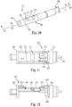
- FIG. 11 is a sectional view as taken along lines 11-11 of FIG. 10, and FIG. 12 is side sectional view as taken along lines 12-12 of FIG. 10 , both of which schematically illustrate sensor element 400, according to one embodiment of the present disclosure.
- this sectional view depicts membrane portion 372 in dashed lines.
- sensor element 400 comprises a housing 412 that contains a pressure sensing element 402 (e.g., pressure transducer) configured to measure sensed changes through or along membrane portion 372 and a temperature sensing element 404 (e.g., temperature transducer) configured to measure temperature.
- a pressure sensing element 402 e.g., pressure transducer
- a temperature sensing element 404 e.g., temperature transducer
- the pressure sensing element 402 is electrically coupled to the temperature sensing element 404, which acts as a temperature compensation unit for pressure sensing element 402.
- the temperature sensing element 404 is positioned away from the membrane portion 372 and the pressure sensing element 402, so that these respective sensing elements 402, 402 are laterally spaced apart to each other, rather than in a stacked configuration.
- the temperature sensing element 404 is electrically coupled to the pressure sensing element 402 in order to cancel temperature effects and thereby produce a sensor element 400 that produces a sensed respiratory signal that primarily indicates changes in pressure and not temperature.
- pressure sensing element 402 comprises a piezo-electric element
- pressure sensing element 402 is substantially more sensitive to changes in temperature than to changes in pressure. Accordingly, in some other embodiments, instead of attempting to cancel out temperature effects, the change in temperature sensed via the piezo-based pressure sensing element 402 is used as a factor in determining whether or not an obstructive sleep apnea event has occurred. As later illustrated in more detail in association with FIGS. 12-13 and 17 , a temperature signal can be used, independent of or with a pressure signal, to identify an obstructive sleep apnea event.
- Sensor element 400 also includes a transistor 408 to process or amplify the signals measured via the pressure sensing element 402 and the temperature sensing element 404.
- the pressure sensing element 402 and/or the temperature sensing element 404 are piezo-electric transducers.
- the respective elements 402, 404 are in electrical communication with a conductive feed element 406 of sensor portion 260 of lead 250 that provides electrical connection out of the hermetically sealed housing 412. This feed element 406, in turn, communicates signals to IPG 55 ( FIG. 1 ) to indicate a respiratory state or effort.
- the respiratory-associated signals produced from the pressure sensing element 402 and the temperature sensing element 404 are mapped independently, as illustrated in FIGS. 13-14 .
- a diagram 500 illustrates a signal 510 mapped as pressure (512) over time (514).
- Signal 510 includes cyclical patterns of inspiration (I) and expiration (E), with diagram 500 also illustrating the nature of these patterns during normal respiration (signal portion 520) and during an obstructive apnea (OSA) event (signal portion 540).
- signal portion 520 includes inspiration portions 530 and expiration portions 532 which have a nominal amplitude (A) and which correspond to generally uniform cyclical amplitudes of respiratory pressure.
- signal portion 540 reveals a substantially greater amplitude of respiratory pressure (such as, 3A or three times the nominal amplitude A in a non-limiting example), indicating increased respiratory efforts through the inspiratory and expiratory phases of the respiration cycle during an obstructive event. Accordingly, these dramatic changes in the cyclical amplitudes of the pressure signal are used to detect obstructive sleep apnea and/or to trigger stimulation therapy for treating the sleep apnea.
- a substantially greater amplitude of respiratory pressure such as, 3A or three times the nominal amplitude A in a non-limiting example
- a diagram 550 illustrates a signal 560 mapped as temperature (562) over time (564).
- Signal 560 includes cyclical patterns of inspiration (I) and expiration (E), with diagram 550 also illustrating the nature of these patterns during normal respiration (signal portion 570) and during an obstructive apnea (OSA) event (signal portion 590).
- signal portion 570 includes inspiration portions 580 and expiration portions 582 which have a nominal amplitude (A), and which correspond to generally uniform cyclical amplitudes of the sensed temperature.
- signal portion 590 reveals little difference between the peaks of the cyclical amplitudes of temperature between inspiration and expiration phases of the respiratory cycle, indicating a reduction of airflow. Accordingly, this lack of difference in the cyclical amplitudes of the temperature signal is used to detect obstructive sleep apnea and/or to trigger stimulation therapy for treating the sleep apnea.
- a temperature signal provides useful information regarding a state of respiration (normal vs. obstructive)
- one of the embodiments of the sensor element 400 described above used the temperature sensing element 404 independent of the pressure sensing element 404, i.e. not to compensate for temperature effects on the pressure signal.
- This temperature signal can stand alone or be combined with a pressure signal.
- the piezo-electric sensing element 402 is used as a temperature sensor alone apart from pressure.
- FIG. 15 is diagram schematically representing an equivalent circuit 600 of the measurement of temperature and pressure via a sensor element, such as sensor element 400 of FIGS. 11-12 , to produce a sensed respiratory signal 620.
- circuit 600 includes a first piezo-electric element 610, a second piezo-electric element 612, and a transistor 614 (e.g., a transistor amplifier circuit).
- a local tissue temperature 630 (where the sensor element 400 is implanted and oriented) is sensed via first piezo-electric element 610 and via second piezo-electric element 612.
- a local tissue pressure 632 (where the sensor element 400 is implanted and oriented) is sensed via second piezo-electric element 612.
- the pressure signal (captured via first sensing element 610) and the temperature signal (captured via second sensing element 612) are summed into one signal 620.
- the first and second piezoelectric elements 610, 612 are electrically coupled together, to permit cancellation of the temperature effects on the sensing of pressure by the second piezoelectric element.
- an equivalent circuit 650 for producing a sensed respiratory signal 670 includes just one piezo-electric element 660 and a transistor amplifier 614.
- both a local tissue temperature 630 and a local pressure 632 (where the sensor element 400 is implanted and oriented) is sensed via the one piezo-electric element 660.
- various combinations of piezoelectric elements with different locations, different sizes, and/or different polarity connections could be created to created to scale the temperature and pressure responses.
- circuit 600 of Fig. 15 and the circuit of Fig. 16 are both implemented in a single sensor housing and, in this arrangement, both of the sensed pressure and sensed temperature signals would be sent separately from each other to the IPG 55.
- a temperature signal and a pressure signal could be provided as input to the pulse generator (e.g., IPG 55 in FIG. 1 ) as two separate signals to preserve maximum signal content.
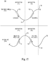
- FIG. 17 is a diagram 700 schematically illustrating a juxtaposition of an independent respiratory temperature signal 702 (through cycles of inspiration 710 and expiration 720) relative to a pressure signal 704 (through cycles of inspiration 710 and expiration 720).
- inspiration 710 the temperature falls in a cooling segment 730 (due to air temperature) and rises in a warming segment 732 (due to blood flow).
- the pressure rises in a negative pressure segment 740 and falls during a positive pressure segment 742.
- the lowest value 731 of the temperature signal 702 occurs simultaneously with a peak 741 of the pressure signal 704.
- the piezo-electric element is mounted and connected with the appropriate polarities to cause the cooling temperature during inspiration and the negative pressure during inspiration to be additive. In this way, one can create an additive temperature and pressure signal.
- the signals from both transducers can be either utilized in combination, or utilized separately in a stand alone configuration to determine whether therapy should be delivered. For example (of utilizing the signals separately) if the pressure is determined to increase beyond a predetermined pressure threshold while at the same time no changes in temperature are sensed due to restricted or obstructed airflow into the lungs, it is concluded that an obstruction has taken place, and therefore therapy is delivered or increased based on the sensed obstruction.
- the pressure is determined to increase beyond the predetermined pressure threshold while at the same time the temperature is also determined to increase beyond a predetermined temperature threshold (which indicates a deep breath rather than an obstruction), then therapy may be withheld.
- further indicators such as input from an activity sensor, for example, may be required before delivery of therapy it is concluded that an obstruction has occurred and therapy is commenced.
- a sensed temperature signal is used to indicate a polarity of the sensed respiratory pressure and thereby differentiate inspiratory phases from expiratory phases of sensed respiratory pressure.
- an inspiratory and expiratory pattern of the sensed temperature signal can be correlated with an inspiratory and expiratory pattern of the sensed respiratory signal. This arrangement is useful in certain instances in which the sensed respiratory pressure signal becomes inverted. In this situation, using the sensed temperature signal to differentiate the inspiratory and expiratory phases allows the IPG 55 to properly synchronize an application of electrical stimulation relative to the inspiratory phase, the expiratory phase, and/or a transition between the respective inspiratory and expiratory phases.
- peak 741 generally corresponds to a transition region (e.g. end of inspiration and/or onset of expiration) between the inspiratory phase (710) and the expiratory phase (720).
- valley 731 generally corresponds to a transition region (e.g. end of inspiration and/or onset of expiration) between the inspiratory phase (710) and the expiratory phase (720).
- transition regions include information regarding the onset of inspiration, onset of expiration, and other related respiration timing fiducials. In one aspect, this information is used to trigger or synchronize the application of an electrical stimulation signal from IPG 55 to a stimulation lead ( FIG. 1 ).
- the pressure and temperature contribution to the sensor are provided above as illustrations of potential sources of input to the sensor signal.
- Other input is also possible, such as the local mechanical force associated with respiratory movement or other motion.
- Embodiments of the present disclosure provide accurate sensing of respiratory effort suitable for detecting, and/or triggering therapy on, an obstructive sleep apnea event.
- a sensing element With sensitivity to pressure and/or temperature, a sensing element provides robust capture of respiratory behavior to more accurately indicate the presence or absence of an obstructive sleep apnea event, thereby leading to a more efficacious delivery of therapy.
Landscapes
- Health & Medical Sciences (AREA)
- Life Sciences & Earth Sciences (AREA)
- Animal Behavior & Ethology (AREA)
- Public Health (AREA)
- General Health & Medical Sciences (AREA)
- Veterinary Medicine (AREA)
- Engineering & Computer Science (AREA)
- Biomedical Technology (AREA)
- Biophysics (AREA)
- Medical Informatics (AREA)
- Molecular Biology (AREA)
- Heart & Thoracic Surgery (AREA)
- Physics & Mathematics (AREA)
- Surgery (AREA)
- Pathology (AREA)
- Physiology (AREA)
- Nuclear Medicine, Radiotherapy & Molecular Imaging (AREA)
- Pulmonology (AREA)
- Radiology & Medical Imaging (AREA)
- Hematology (AREA)
- Neurology (AREA)
- Neurosurgery (AREA)
- Measurement Of The Respiration, Hearing Ability, Form, And Blood Characteristics Of Living Organisms (AREA)
- Electrotherapy Devices (AREA)
- Measurement And Recording Of Electrical Phenomena And Electrical Characteristics Of The Living Body (AREA)
Claims (12)
- Système de capteur respiratoire implantable comprenant :un fil de capteur (200) comprenant un corps de fil (202) et une partie de capteur (210), la partie de capteur (210) s'étendant depuis le corps de fil (202) et comprenant au moins un transducteur indicateur de pression ; etune première ancre située à une position fixe par rapport à la partie de capteur (210), dans lequel le transducteur indicateur de pression définit un élément de détection directionnel (212) configuré pour détecter la pression respiratoire sur un seul côté de la partie de capteur (210), dans lequel la première ancre comprend une paire de bras élastiques qui s'étendent vers l'extérieur depuis des côtés opposés du corps de fil, et généralement de manière perpendiculaire à ce dernier, pour empêcher la rotation de l'élément de détection directionnel pour maintenir l'orientation du seul côté par rapport au tissu qui doit être détecté, et dans lequel la première ancre est située au niveau de la partie de capteur adjacente à une extrémité distale du corps de fil.
- Système de capteur selon la revendication 1, comprenant :
une seconde ancre située sur le corps de fil (202) de manière proximale à la première ancre et qui peut être déplacée de manière sélective le long d'une longueur du corps de fil (202) de sorte à être espacée de manière sélective de la première ancre. - Système de capteur selon la revendication 1, dans lequel la partie de capteur (210) comprend facultativement la pointe distale du fil de capteur (200) .
- Système de capteur selon la revendication 1, dans lequel la première ancre est proximale à la partie de capteur (210), et espacée de cette dernière, par une distance allant d'environ 3 à 9 centimètres le long d'une longueur du corps de fil (202).
- Système de capteur selon la revendication 1, dans lequel à la fois la première ancre et le transducteur indicateur de pression sont configurés pour être placés à l'intérieur d'au moins une couche de muscle dans une position extrapleurale intercostale.
- Système de capteur selon la revendication 5, dans lequel
la ou les couches de muscle comprennent de multiples couches de muscle et la position extrapleurale est entre les multiples couches de muscle et/ou
le tissu comprend des tissus conjonctifs associés à la ou aux couches de muscle. - Système de capteur selon la revendication 1, dans lequel
une partie distale du corps de fil (202), comprenant la partie de capteur (210), est configurée pour être insérée à travers un point d'accès intercostal pour orienter la partie distale pour être généralement parallèle à une paire de côtes immédiatement adjacentes et pour pointer vers une ligne centrale du corps. - Système selon la revendication 7, dans lequel la partie de capteur (210) est espacée de la première ancre pour pouvoir être implantée à un emplacement latéral à une articulation costo-chondrale des côtes adjacentes.
- Système selon la revendication 7, dans lequel la première ancre est espacée de la partie de capteur (210) pour pouvoir être fixée à un tissu conjonctif sous-cutané qui est externe au point d'accès intercostal.
- Système selon la revendication 1, comprenant :
une seconde ancre proximale à la première ancre fixe et pouvant être déplacée de manière sélective le long du corps de fil (202) sur une certaine longueur pour fixer le corps de fil (202) par rapport à une partie de côté latéral du corps du patient pour provoquer une extension du corps de fil (202) le long du côté latéral du corps du patient pour un raccordement à un générateur d'impulsions implantable. - Système selon la revendication 1, dans lequel le fil de capteur (200) comprend une pointe distale, dans lequel le transducteur indicateur de pression est proximal à la pointe distale.
- Système selon la revendication 1, dans lequel la première ancre est proximale à une pointe distale du fil de capteur (200).
Priority Applications (1)
| Application Number | Priority Date | Filing Date | Title |
|---|---|---|---|
| EP20153950.9A EP3708219B1 (fr) | 2008-05-15 | 2009-05-15 | Appareil de détection de la pression respiratoire dans un système de stimulation implantable |
Applications Claiming Priority (3)
| Application Number | Priority Date | Filing Date | Title |
|---|---|---|---|
| US5334408P | 2008-05-15 | 2008-05-15 | |
| EP09747717.8A EP2323730B1 (fr) | 2008-05-15 | 2009-05-15 | Appareil permettant de détecter la pression respiratoire dans un système de stimulation implantable |
| PCT/US2009/044207 WO2009140636A2 (fr) | 2008-05-15 | 2009-05-15 | Procédé et appareil permettant de détecter la pression respiratoire dans un système de stimulation implantable |
Related Parent Applications (2)
| Application Number | Title | Priority Date | Filing Date |
|---|---|---|---|
| EP09747717.8A Division-Into EP2323730B1 (fr) | 2008-05-15 | 2009-05-15 | Appareil permettant de détecter la pression respiratoire dans un système de stimulation implantable |
| EP09747717.8A Division EP2323730B1 (fr) | 2008-05-15 | 2009-05-15 | Appareil permettant de détecter la pression respiratoire dans un système de stimulation implantable |
Related Child Applications (2)
| Application Number | Title | Priority Date | Filing Date |
|---|---|---|---|
| EP20153950.9A Division EP3708219B1 (fr) | 2008-05-15 | 2009-05-15 | Appareil de détection de la pression respiratoire dans un système de stimulation implantable |
| EP20153950.9A Division-Into EP3708219B1 (fr) | 2008-05-15 | 2009-05-15 | Appareil de détection de la pression respiratoire dans un système de stimulation implantable |
Publications (2)
| Publication Number | Publication Date |
|---|---|
| EP3181191A1 EP3181191A1 (fr) | 2017-06-21 |
| EP3181191B1 true EP3181191B1 (fr) | 2020-03-11 |
Family
ID=40873477
Family Applications (3)
| Application Number | Title | Priority Date | Filing Date |
|---|---|---|---|
| EP20153950.9A Active EP3708219B1 (fr) | 2008-05-15 | 2009-05-15 | Appareil de détection de la pression respiratoire dans un système de stimulation implantable |
| EP09747717.8A Active EP2323730B1 (fr) | 2008-05-15 | 2009-05-15 | Appareil permettant de détecter la pression respiratoire dans un système de stimulation implantable |
| EP16192561.5A Active EP3181191B1 (fr) | 2008-05-15 | 2009-05-15 | Appareil de détection de pression respiratoire dans un système de stimulation implantable |
Family Applications Before (2)
| Application Number | Title | Priority Date | Filing Date |
|---|---|---|---|
| EP20153950.9A Active EP3708219B1 (fr) | 2008-05-15 | 2009-05-15 | Appareil de détection de la pression respiratoire dans un système de stimulation implantable |
| EP09747717.8A Active EP2323730B1 (fr) | 2008-05-15 | 2009-05-15 | Appareil permettant de détecter la pression respiratoire dans un système de stimulation implantable |
Country Status (6)
| Country | Link |
|---|---|
| US (3) | US20110152706A1 (fr) |
| EP (3) | EP3708219B1 (fr) |
| JP (2) | JP5518053B2 (fr) |
| AU (1) | AU2009246179A1 (fr) |
| CA (1) | CA2724335A1 (fr) |
| WO (1) | WO2009140636A2 (fr) |
Families Citing this family (62)
| Publication number | Priority date | Publication date | Assignee | Title |
|---|---|---|---|---|
| US20050149132A1 (en) | 2003-12-24 | 2005-07-07 | Imad Libbus | Automatic baroreflex modulation based on cardiac activity |
| WO2007098202A2 (fr) | 2006-02-16 | 2007-08-30 | Imthera Medical, Inc. | Appareil, système et procédé rfid de traitement thérapeutique d'un patient |
| US9658178B2 (en) | 2012-09-28 | 2017-05-23 | General Electric Company | Sensor systems for measuring an interface level in a multi-phase fluid composition |
| US20110320142A1 (en) * | 2010-06-28 | 2011-12-29 | General Electric Company | Temperature independent pressure sensor and associated methods thereof |
| US10914698B2 (en) | 2006-11-16 | 2021-02-09 | General Electric Company | Sensing method and system |
| US9538657B2 (en) | 2012-06-29 | 2017-01-03 | General Electric Company | Resonant sensor and an associated sensing method |
| US9589686B2 (en) | 2006-11-16 | 2017-03-07 | General Electric Company | Apparatus for detecting contaminants in a liquid and a system for use thereof |
| US9536122B2 (en) | 2014-11-04 | 2017-01-03 | General Electric Company | Disposable multivariable sensing devices having radio frequency based sensors |
| CA2697826A1 (fr) | 2007-10-09 | 2009-04-16 | Imthera Medical, Inc. | Systeme et procede de stimulation neuronale |
| CA2722982A1 (fr) | 2008-05-02 | 2009-11-05 | Medtronic, Inc. | Ballonnet a electrodes autogonflable |
| US8340785B2 (en) | 2008-05-02 | 2012-12-25 | Medtronic, Inc. | Self expanding electrode cuff |
| WO2009140636A2 (fr) | 2008-05-15 | 2009-11-19 | Inspire Medical Systems, Inc. | Procédé et appareil permettant de détecter la pression respiratoire dans un système de stimulation implantable |
| US9889299B2 (en) | 2008-10-01 | 2018-02-13 | Inspire Medical Systems, Inc. | Transvenous method of treating sleep apnea |
| WO2010042404A1 (fr) | 2008-10-09 | 2010-04-15 | Imthera Medical, Inc. | Procédé de stimulation d’un nerf grand hypoglosse pour contrôler la position de la langue d’un patient |
| WO2010059839A2 (fr) | 2008-11-19 | 2010-05-27 | Inspire Medical Systems, Inc. | Procédé de traitement de troubles respiratoires du sommeil |
| US8515520B2 (en) | 2008-12-08 | 2013-08-20 | Medtronic Xomed, Inc. | Nerve electrode |
| US9486628B2 (en) | 2009-03-31 | 2016-11-08 | Inspire Medical Systems, Inc. | Percutaneous access for systems and methods of treating sleep apnea |
| US9950166B2 (en) | 2009-10-20 | 2018-04-24 | Nyxoah SA | Acred implant unit for modulation of nerves |
| US9409013B2 (en) | 2009-10-20 | 2016-08-09 | Nyxoah SA | Method for controlling energy delivery as a function of degree of coupling |
| US10751537B2 (en) | 2009-10-20 | 2020-08-25 | Nyxoah SA | Arced implant unit for modulation of nerves |
| JP2013509943A (ja) | 2009-11-10 | 2013-03-21 | イムセラ・メディカル・インコーポレーテッド | 舌下神経を刺激して患者の舌の位置を調節するシステム |
| EP3381366A1 (fr) | 2010-03-12 | 2018-10-03 | Inspire Medical Systems, Inc. | Système pour identifier un emplacement de stimulation nerveuse |
| US8983572B2 (en) | 2010-10-29 | 2015-03-17 | Inspire Medical Systems, Inc. | System and method for patient selection in treating sleep disordered breathing |
| US8542023B2 (en) | 2010-11-09 | 2013-09-24 | General Electric Company | Highly selective chemical and biological sensors |
| JP6092212B2 (ja) | 2011-08-11 | 2017-03-08 | インスパイア・メディカル・システムズ・インコーポレイテッドInspire Medical Systems, Inc. | 呼吸努力の検知結果に基づいて刺激プロトコルを選択するためのシステム |
| US8934992B2 (en) | 2011-09-01 | 2015-01-13 | Inspire Medical Systems, Inc. | Nerve cuff |
| US8983611B2 (en) | 2011-09-27 | 2015-03-17 | Cardiac Pacemakers, Inc. | Neural control of central sleep apnea |
| US10052097B2 (en) | 2012-07-26 | 2018-08-21 | Nyxoah SA | Implant unit delivery tool |
| US9907967B2 (en) | 2012-07-26 | 2018-03-06 | Adi Mashiach | Transcutaneous power conveyance device |
| US11253712B2 (en) | 2012-07-26 | 2022-02-22 | Nyxoah SA | Sleep disordered breathing treatment apparatus |
| WO2014016701A2 (fr) | 2012-07-26 | 2014-01-30 | Adi Mashiach | Adaptation de résonance externe entre un dispositif implanté et un dispositif externe |
| JP6251270B2 (ja) | 2012-08-22 | 2017-12-20 | ゼネラル・エレクトリック・カンパニイ | 機械の動作状態を測定するためのワイヤレスシステムおよび方法 |
| US10598650B2 (en) | 2012-08-22 | 2020-03-24 | General Electric Company | System and method for measuring an operative condition of a machine |
| US10684268B2 (en) | 2012-09-28 | 2020-06-16 | Bl Technologies, Inc. | Sensor systems for measuring an interface level in a multi-phase fluid composition |
| KR20160100291A (ko) | 2013-06-17 | 2016-08-23 | 아디 매쉬아취 | 치료 기간에 걸친 조절의 동적 수정 |
| US9636505B2 (en) | 2014-11-24 | 2017-05-02 | AtaCor Medical, Inc. | Cardiac pacing sensing and control |
| EP3188793B1 (fr) | 2014-09-04 | 2020-01-01 | Atacor Medical, Inc. | Élément de réception pour fil conducteur de stimulateur cardiaque |
| US10743960B2 (en) * | 2014-09-04 | 2020-08-18 | AtaCor Medical, Inc. | Cardiac arrhythmia treatment devices and delivery |
| US10328268B2 (en) | 2014-09-04 | 2019-06-25 | AtaCor Medical, Inc. | Cardiac pacing |
| US11097109B2 (en) | 2014-11-24 | 2021-08-24 | AtaCor Medical, Inc. | Cardiac pacing sensing and control |
| EP3271008B1 (fr) | 2015-03-19 | 2024-09-25 | Inspire Medical Systems, Inc. | Stimulation pour le traitement de troubles respiratoires du sommeil |
| US20190175026A1 (en) | 2015-11-11 | 2019-06-13 | Inspire Medical Systems, Inc. | Cardiac and sleep monitoring |
| WO2017087681A1 (fr) | 2015-11-17 | 2017-05-26 | Inspire Medical Systems, Inc. | Dispositif de traitement par microstimulation pour les troubles respiratoires du sommeil (sdb) |
| US20170202513A1 (en) * | 2015-12-09 | 2017-07-20 | The Alfred E. Mann Foundation For Scientific Research | Implantable pressure sensors and medical devices |
| EP3445444A1 (fr) | 2016-04-19 | 2019-02-27 | Inspire Medical Systems, Inc. | Détection fondée sur l'utilisation d'un accéléromètre pour soigner les troubles respiratoires du sommeil (sdb) |
| JP2019535396A (ja) | 2016-11-10 | 2019-12-12 | ザ リサーチ ファウンデーション フォー ザ ステート ユニバーシティ オブ ニューヨーク | 気道閉塞に関するシステム、方法、及びバイオマーカ |
| WO2018132713A1 (fr) * | 2017-01-12 | 2018-07-19 | Tc1 Llc | Ancrages osseux pour arbre d'entraînement et procédés d'utilisation |
| WO2018132708A1 (fr) | 2017-01-12 | 2018-07-19 | Tc1 Llc | Dispositifs d'ancrage de ligne de transmission percutanée et procédés d'utilisation |
| AU2018316277B2 (en) | 2017-08-11 | 2023-12-07 | Inspire Medical Systems, Inc. | Cuff electrode |
| WO2020102193A1 (fr) | 2018-11-13 | 2020-05-22 | Inspire Medical Systems, Inc. | Apnée du sommeil de type multiple |
| WO2020163292A1 (fr) | 2019-02-05 | 2020-08-13 | Inspire Medical Systems, Inc. | Incision d'accès d'implant et détection permettant de soigner des troubles respiratoires du sommeil (sdb) |
| CA3141999A1 (fr) | 2019-05-29 | 2020-12-03 | AtaCor Medical, Inc. | Fils electriques implantables et systemes de mise en place associes |
| CN114401665A (zh) | 2019-07-25 | 2022-04-26 | 启迪医疗仪器公司 | 呼吸检测 |
| JP7522821B2 (ja) | 2019-07-25 | 2024-07-25 | インスパイア・メディカル・システムズ・インコーポレイテッド | 睡眠呼吸障害(sdb)ケアのための睡眠検出 |
| US11666771B2 (en) | 2020-05-29 | 2023-06-06 | AtaCor Medical, Inc. | Implantable electrical leads and associated delivery systems |
| EP4185191A1 (fr) | 2020-07-24 | 2023-05-31 | Inspire Medical Systems, Inc. | Indication de charge de maladie |
| JP2023548970A (ja) | 2020-11-04 | 2023-11-21 | インヴィクタ メディカル インコーポレイテッド | 睡眠時無呼吸を治療するための遠隔給電式植え込み型電極並びに関連システム及び方法 |
| WO2022169699A1 (fr) | 2021-02-04 | 2022-08-11 | Inspire Medical Systems, Inc. | Dispositifs médicaux implantables au moins partiellement formés à partir d'un matériau thermodurcissable |
| US11964154B1 (en) | 2022-12-22 | 2024-04-23 | Invicta Medical, Inc. | Signal delivery devices to treat sleep apnea, and associated methods and systems |
| WO2024145123A1 (fr) | 2022-12-29 | 2024-07-04 | Inspire Medical Systems, Inc. | Détection du sommeil |
| WO2024145127A1 (fr) | 2022-12-29 | 2024-07-04 | Inspire Medical Systems, Inc. | Éligibilité de patient pour l'initiation automatique d'une thérapie sur la base de la variabilité de latence d'endormissement |
| WO2024145116A1 (fr) | 2022-12-29 | 2024-07-04 | Inspire Medical Systems, Inc. | Détection d'endormissement et de réveil |
Family Cites Families (112)
| Publication number | Priority date | Publication date | Assignee | Title |
|---|---|---|---|---|
| IT1156564B (it) * | 1982-03-16 | 1987-02-04 | Gianni Plicchi | Elettrostimolatore cardiaco impiantabile, di tipo fisiologico, in cui la frequenza di stimolazione e'regolata dalla frequenza respiratoria del paziente |
| US4813431A (en) * | 1987-07-22 | 1989-03-21 | David Brown | Intrapulmonary pressure monitoring system |
| US5098442A (en) | 1989-12-06 | 1992-03-24 | Medtronic, Inc. | Muscle contraction control by intramuscular pressure monitoring |
| US5158080A (en) * | 1990-11-08 | 1992-10-27 | Medtronic, Inc. | Muscle tone |
| US5107856A (en) * | 1991-01-10 | 1992-04-28 | Siemens-Pacesetter, Inc. | Multiple lead suture sleeve |
| US5353800A (en) * | 1992-12-11 | 1994-10-11 | Medtronic, Inc. | Implantable pressure sensor lead |
| US5344438A (en) * | 1993-04-16 | 1994-09-06 | Medtronic, Inc. | Cuff electrode |
| US5423763A (en) * | 1993-06-17 | 1995-06-13 | Pacesetter, Inc. | Protective, visible suture sleeve for anchoring transvenous lead bodies |
| US5485851A (en) * | 1994-09-21 | 1996-01-23 | Medtronic, Inc. | Method and apparatus for arousal detection |
| US5546952A (en) * | 1994-09-21 | 1996-08-20 | Medtronic, Inc. | Method and apparatus for detection of a respiratory waveform |
| US5540731A (en) * | 1994-09-21 | 1996-07-30 | Medtronic, Inc. | Method and apparatus for pressure detecting and treating obstructive airway disorders |
| US5540732A (en) * | 1994-09-21 | 1996-07-30 | Medtronic, Inc. | Method and apparatus for impedance detecting and treating obstructive airway disorders |
| US5540733A (en) * | 1994-09-21 | 1996-07-30 | Medtronic, Inc. | Method and apparatus for detecting and treating obstructive sleep apnea |
| US5876429A (en) * | 1995-06-07 | 1999-03-02 | Intermedics, Inc. | Methods and devices for in vivo repair of cardiac stimulator leads |
| US6198970B1 (en) * | 1995-10-27 | 2001-03-06 | Esd Limited Liability Company | Method and apparatus for treating oropharyngeal respiratory and oral motor neuromuscular disorders with electrical stimulation |
| GB9524968D0 (en) * | 1995-12-06 | 1996-02-07 | Brown Brian H | Impedance pneumography |
| JPH09215757A (ja) * | 1996-02-09 | 1997-08-19 | Medtronic Inc | 上部気道障害を処理するための医療用装置 |
| US5860938A (en) * | 1996-03-07 | 1999-01-19 | Scimed Life Systems, Inc. | Medical pressure sensing guide wire |
| US6099479A (en) * | 1996-06-26 | 2000-08-08 | Medtronic, Inc. | Method and apparatus for operating therapy system |
| US5944680A (en) * | 1996-06-26 | 1999-08-31 | Medtronic, Inc. | Respiratory effort detection method and apparatus |
| US6132384A (en) * | 1996-06-26 | 2000-10-17 | Medtronic, Inc. | Sensor, method of sensor implant and system for treatment of respiratory disorders |
| US5895360A (en) * | 1996-06-26 | 1999-04-20 | Medtronic, Inc. | Gain control for a periodic signal and method regarding same |
| JP3441332B2 (ja) * | 1997-03-12 | 2003-09-02 | 株式会社カージオペーシングリサーチ・ラボラトリー | 植え込み可能な電極リード |
| US5919221A (en) * | 1997-04-22 | 1999-07-06 | Medtronic, Inc | Method and apparatus for calibrating pacemaker pressure sensor lead prior to chronic implant |
| US5916221A (en) * | 1997-09-17 | 1999-06-29 | Bristol-Myers Squibb Company | Notch/chamfer guide |
| US6022322A (en) * | 1998-02-06 | 2000-02-08 | Intermedics Inc. | Non-invasive cardiorespiratory monitor with synchronized bioimpedance sensing |
| SE9802335D0 (sv) * | 1998-06-30 | 1998-06-30 | Siemens Elema Ab | Andningshjälpsystem |
| US6240316B1 (en) * | 1998-08-14 | 2001-05-29 | Advanced Bionics Corporation | Implantable microstimulation system for treatment of sleep apnea |
| US6309350B1 (en) * | 1999-05-03 | 2001-10-30 | Tricardia, L.L.C. | Pressure/temperature/monitor device for heart implantation |
| US6770070B1 (en) | 2000-03-17 | 2004-08-03 | Rita Medical Systems, Inc. | Lung treatment apparatus and method |
| US20020035381A1 (en) * | 2000-09-18 | 2002-03-21 | Cameron Health, Inc. | Subcutaneous electrode with improved contact shape for transthoracic conduction |
| US7054692B1 (en) * | 2001-06-22 | 2006-05-30 | Advanced Bionics Corporation | Fixation device for implantable microdevices |
| US7160255B2 (en) * | 2001-07-12 | 2007-01-09 | Vahid Saadat | Method and device for sensing and mapping temperature profile of a hollow body organ |
| US8777851B2 (en) * | 2001-10-01 | 2014-07-15 | Medtronic, Inc. | Congestive heart failure monitor and ventilation measuring implant |
| US6712772B2 (en) * | 2001-11-29 | 2004-03-30 | Biocontrol Medical Ltd. | Low power consumption implantable pressure sensor |
| FR2833177B1 (fr) * | 2001-12-07 | 2004-06-04 | Ela Medical Sa | Dispositif medical actif comprenant des moyens perfectionnes de discrimination des phases d'eveil et de sommeil |
| FI116097B (fi) * | 2002-08-21 | 2005-09-15 | Heikki Ruotoistenmaeki | Voima- tai paineanturi ja menetelmä sen soveltamiseksi |
| JP2004121668A (ja) * | 2002-10-04 | 2004-04-22 | Denso Corp | 呼吸異常検出装置及び測定装置並びに呼吸異常検出方法 |
| US7252640B2 (en) * | 2002-12-04 | 2007-08-07 | Cardiac Pacemakers, Inc. | Detection of disordered breathing |
| US7189204B2 (en) * | 2002-12-04 | 2007-03-13 | Cardiac Pacemakers, Inc. | Sleep detection using an adjustable threshold |
| US20060111626A1 (en) * | 2003-03-27 | 2006-05-25 | Cvrx, Inc. | Electrode structures having anti-inflammatory properties and methods of use |
| US20050261747A1 (en) * | 2003-05-16 | 2005-11-24 | Schuler Eleanor L | Method and system to control respiration by means of neuro-electrical coded signals |
| US7186220B2 (en) * | 2003-07-02 | 2007-03-06 | Cardiac Pacemakers, Inc. | Implantable devices and methods using frequency-domain analysis of thoracic signal |
| US7200440B2 (en) * | 2003-07-02 | 2007-04-03 | Cardiac Pacemakers, Inc. | Cardiac cycle synchronized sampling of impedance signal |
| US7396333B2 (en) * | 2003-08-18 | 2008-07-08 | Cardiac Pacemakers, Inc. | Prediction of disordered breathing |
| US7678061B2 (en) * | 2003-09-18 | 2010-03-16 | Cardiac Pacemakers, Inc. | System and method for characterizing patient respiration |
| US7572225B2 (en) | 2003-09-18 | 2009-08-11 | Cardiac Pacemakers, Inc. | Sleep logbook |
| US7469697B2 (en) * | 2003-09-18 | 2008-12-30 | Cardiac Pacemakers, Inc. | Feedback system and method for sleep disordered breathing therapy |
| US7510531B2 (en) * | 2003-09-18 | 2009-03-31 | Cardiac Pacemakers, Inc. | System and method for discrimination of central and obstructive disordered breathing events |
| US7336996B2 (en) * | 2003-09-18 | 2008-02-26 | Cardiac Pacemakers, Inc. | Rate regularization of cardiac pacing for disordered breathing therapy |
| US7787946B2 (en) * | 2003-08-18 | 2010-08-31 | Cardiac Pacemakers, Inc. | Patient monitoring, diagnosis, and/or therapy systems and methods |
| US7720541B2 (en) * | 2003-08-18 | 2010-05-18 | Cardiac Pacemakers, Inc. | Adaptive therapy for disordered breathing |
| US7468040B2 (en) * | 2003-09-18 | 2008-12-23 | Cardiac Pacemakers, Inc. | Methods and systems for implantably monitoring external breathing therapy |
| US7591265B2 (en) * | 2003-09-18 | 2009-09-22 | Cardiac Pacemakers, Inc. | Coordinated use of respiratory and cardiac therapies for sleep disordered breathing |
| US8606356B2 (en) * | 2003-09-18 | 2013-12-10 | Cardiac Pacemakers, Inc. | Autonomic arousal detection system and method |
| US8002553B2 (en) * | 2003-08-18 | 2011-08-23 | Cardiac Pacemakers, Inc. | Sleep quality data collection and evaluation |
| US7680537B2 (en) * | 2003-08-18 | 2010-03-16 | Cardiac Pacemakers, Inc. | Therapy triggered by prediction of disordered breathing |
| EP1512430B1 (fr) * | 2003-09-02 | 2008-02-13 | Biotronik GmbH & Co. KG | Dispositif de traitement des apnées du sommeil |
| US8467876B2 (en) * | 2003-10-15 | 2013-06-18 | Rmx, Llc | Breathing disorder detection and therapy delivery device and method |
| US8244358B2 (en) * | 2003-10-15 | 2012-08-14 | Rmx, Llc | Device and method for treating obstructive sleep apnea |
| US7979128B2 (en) | 2003-10-15 | 2011-07-12 | Rmx, Llc | Device and method for gradually controlling breathing |
| US8050531B2 (en) | 2006-09-27 | 2011-11-01 | Anis Rahman | Dendrimer based terahertz generator |
| US8160711B2 (en) | 2003-10-15 | 2012-04-17 | Rmx, Llc | Multimode device and method for controlling breathing |
| WO2005058133A2 (fr) * | 2003-12-11 | 2005-06-30 | Proteus Biomedical, Inc. | Capteurs de pression implantables |
| US7783353B2 (en) * | 2003-12-24 | 2010-08-24 | Cardiac Pacemakers, Inc. | Automatic neural stimulation modulation based on activity and circadian rhythm |
| US7002365B2 (en) * | 2003-12-30 | 2006-02-21 | Intel Corporation | Method and an apparatus for testing transmitter and receiver |
| US7519425B2 (en) * | 2004-01-26 | 2009-04-14 | Pacesetter, Inc. | Tiered therapy for respiratory oscillations characteristic of Cheyne-Stokes respiration |
| US20050209512A1 (en) * | 2004-03-16 | 2005-09-22 | Heruth Kenneth T | Detecting sleep |
| US7395113B2 (en) * | 2004-03-16 | 2008-07-01 | Medtronic, Inc. | Collecting activity information to evaluate therapy |
| US7792583B2 (en) * | 2004-03-16 | 2010-09-07 | Medtronic, Inc. | Collecting posture information to evaluate therapy |
| WO2005089646A1 (fr) * | 2004-03-16 | 2005-09-29 | Medtronic, Inc. | Analyse de sensibilite pour la selection d'ensembles de parametres |
| US7330760B2 (en) * | 2004-03-16 | 2008-02-12 | Medtronic, Inc. | Collecting posture information to evaluate therapy |
| US7881798B2 (en) * | 2004-03-16 | 2011-02-01 | Medtronic Inc. | Controlling therapy based on sleep quality |
| US7717848B2 (en) * | 2004-03-16 | 2010-05-18 | Medtronic, Inc. | Collecting sleep quality information via a medical device |
| US7491181B2 (en) * | 2004-03-16 | 2009-02-17 | Medtronic, Inc. | Collecting activity and sleep quality information via a medical device |
| US7366572B2 (en) * | 2004-03-16 | 2008-04-29 | Medtronic, Inc. | Controlling therapy based on sleep quality |
| FR2868323B1 (fr) * | 2004-04-05 | 2006-06-02 | Ela Medical Sa | Dispositif medical implantable actif pourvu de moyens de diagnostic de troubles respiratoires, a detection perfectionnee des cycles respiratoires artefactes |
| US8489189B2 (en) | 2004-10-29 | 2013-07-16 | Medtronic, Inc. | Expandable fixation mechanism |
| DE602005026054D1 (de) * | 2004-12-17 | 2011-03-03 | Medtronic Inc | System zur überwachung oder behandlung von erkrankungen des nervensystems |
| US7680534B2 (en) * | 2005-02-28 | 2010-03-16 | Cardiac Pacemakers, Inc. | Implantable cardiac device with dyspnea measurement |
| US7805195B2 (en) * | 2005-03-24 | 2010-09-28 | Vanderbilt University | Respiratory triggered, bilateral laryngeal stimulator to restore normal ventilation in vocal fold paralysis |
| WO2006119015A1 (fr) * | 2005-04-30 | 2006-11-09 | Medtronic, Inc. | Ajustement de stimulation sur la base d'une impedance |
| US7644714B2 (en) * | 2005-05-27 | 2010-01-12 | Apnex Medical, Inc. | Devices and methods for treating sleep disorders |
| WO2006130268A1 (fr) | 2005-06-01 | 2006-12-07 | Medtronic, Inc. | Correlation d'un ensemble de parametres physiologiques non polysomnographiques avec des etats de sommeil |
| US20060276701A1 (en) * | 2005-06-03 | 2006-12-07 | Ray Charles D | Detection and stimulus conditioning system for sleep apnea |
| WO2007011486A2 (fr) | 2005-07-19 | 2007-01-25 | Catalina Marketing Corporation | Systeme de marketing cible pour les restaurants et les etablissements par les fabricants et distributeurs de services de restauration |
| US7128717B1 (en) * | 2005-09-29 | 2006-10-31 | Washington University | Method for determining airway obstruction |
| US7477323B2 (en) * | 2005-11-07 | 2009-01-13 | Kolorific, Inc. | Method and system for digital image magnification and reduction |
| US8016776B2 (en) | 2005-12-02 | 2011-09-13 | Medtronic, Inc. | Wearable ambulatory data recorder |
| US7957797B2 (en) | 2005-12-02 | 2011-06-07 | Medtronic, Inc. | Closed-loop therapy adjustment |
| US7853322B2 (en) * | 2005-12-02 | 2010-12-14 | Medtronic, Inc. | Closed-loop therapy adjustment |
| US7957809B2 (en) | 2005-12-02 | 2011-06-07 | Medtronic, Inc. | Closed-loop therapy adjustment |
| WO2007098202A2 (fr) * | 2006-02-16 | 2007-08-30 | Imthera Medical, Inc. | Appareil, système et procédé rfid de traitement thérapeutique d'un patient |
| CA2550382C (fr) * | 2006-06-05 | 2012-03-13 | Synoil Fluids Holdings Inc. | Recyclage de fluide de stimulation hydraulique d'hydrocarbures |
| US7660632B2 (en) * | 2006-06-30 | 2010-02-09 | Ric Investments, Llc | Method and apparatus for hypoglossal nerve stimulation |
| WO2008048471A2 (fr) * | 2006-10-13 | 2008-04-24 | Apnex Medical, Inc. | Dispositifs, systèmes et procédés de traitement d'apnée du sommeil obstructive |
| US9744354B2 (en) * | 2008-12-31 | 2017-08-29 | Cyberonics, Inc. | Obstructive sleep apnea treatment devices, systems and methods |
| US7634315B2 (en) * | 2007-05-31 | 2009-12-15 | Pacesetter, Inc. | Techniques to monitor and trend nerve damage and recovery |
| CA2697826A1 (fr) * | 2007-10-09 | 2009-04-16 | Imthera Medical, Inc. | Systeme et procede de stimulation neuronale |
| US8135479B2 (en) * | 2008-04-23 | 2012-03-13 | Medtronic, Inc. | Sensor assemblies for implantable medical electrical leads |
| CA2722982A1 (fr) | 2008-05-02 | 2009-11-05 | Medtronic, Inc. | Ballonnet a electrodes autogonflable |
| US8340785B2 (en) | 2008-05-02 | 2012-12-25 | Medtronic, Inc. | Self expanding electrode cuff |
| WO2009140636A2 (fr) | 2008-05-15 | 2009-11-19 | Inspire Medical Systems, Inc. | Procédé et appareil permettant de détecter la pression respiratoire dans un système de stimulation implantable |
| US9889299B2 (en) | 2008-10-01 | 2018-02-13 | Inspire Medical Systems, Inc. | Transvenous method of treating sleep apnea |
| WO2010042404A1 (fr) * | 2008-10-09 | 2010-04-15 | Imthera Medical, Inc. | Procédé de stimulation d’un nerf grand hypoglosse pour contrôler la position de la langue d’un patient |
| EP2364178A1 (fr) * | 2008-10-13 | 2011-09-14 | E- Pacing, Inc. | Dispositifs et procédés de stimulation électrique du diaphragme et des nerfs |
| US8616213B2 (en) | 2008-11-11 | 2013-12-31 | J3 Group, Llc | Earplug insertion device |
| WO2010059839A2 (fr) | 2008-11-19 | 2010-05-27 | Inspire Medical Systems, Inc. | Procédé de traitement de troubles respiratoires du sommeil |
| US9486628B2 (en) | 2009-03-31 | 2016-11-08 | Inspire Medical Systems, Inc. | Percutaneous access for systems and methods of treating sleep apnea |
| US8175720B2 (en) | 2009-04-30 | 2012-05-08 | Medtronic, Inc. | Posture-responsive therapy control based on patient input |
| US8585617B2 (en) | 2009-12-21 | 2013-11-19 | Nyxoah SA | Diagnosis and prediction of obstructive sleep apnea |
| US10806926B2 (en) | 2009-10-20 | 2020-10-20 | Man & Science Sa | Implantable electrical stimulator |
-
2009
- 2009-05-15 WO PCT/US2009/044207 patent/WO2009140636A2/fr active Application Filing
- 2009-05-15 AU AU2009246179A patent/AU2009246179A1/en not_active Abandoned
- 2009-05-15 EP EP20153950.9A patent/EP3708219B1/fr active Active
- 2009-05-15 CA CA2724335A patent/CA2724335A1/fr not_active Abandoned
- 2009-05-15 EP EP09747717.8A patent/EP2323730B1/fr active Active
- 2009-05-15 JP JP2011509769A patent/JP5518053B2/ja active Active
- 2009-05-15 US US12/992,511 patent/US20110152706A1/en not_active Abandoned
- 2009-05-15 EP EP16192561.5A patent/EP3181191B1/fr active Active
-
2014
- 2014-04-01 JP JP2014075355A patent/JP5800942B2/ja active Active
-
2017
- 2017-08-29 US US15/689,275 patent/US10932682B2/en active Active
-
2021
- 2021-02-26 US US17/186,473 patent/US20210290093A1/en not_active Abandoned
Non-Patent Citations (1)
| Title |
|---|
| None * |
Also Published As
| Publication number | Publication date |
|---|---|
| WO2009140636A2 (fr) | 2009-11-19 |
| JP5800942B2 (ja) | 2015-10-28 |
| WO2009140636A3 (fr) | 2010-03-11 |
| US20110152706A1 (en) | 2011-06-23 |
| US20180103860A1 (en) | 2018-04-19 |
| EP2323730B1 (fr) | 2016-11-16 |
| EP3181191A1 (fr) | 2017-06-21 |
| US10932682B2 (en) | 2021-03-02 |
| JP2014158936A (ja) | 2014-09-04 |
| US20210290093A1 (en) | 2021-09-23 |
| EP3708219B1 (fr) | 2022-08-03 |
| CA2724335A1 (fr) | 2009-11-19 |
| AU2009246179A1 (en) | 2009-11-19 |
| EP2323730A2 (fr) | 2011-05-25 |
| JP2011520526A (ja) | 2011-07-21 |
| JP5518053B2 (ja) | 2014-06-11 |
| EP3708219A1 (fr) | 2020-09-16 |
Similar Documents
| Publication | Publication Date | Title |
|---|---|---|
| US20210290093A1 (en) | Method of Sensing Pressure for an Implantable Stimulation System | |
| US11806537B2 (en) | Transvenous method of treating sleep apnea | |
| EP2310084B1 (fr) | Système de fil d électrode | |
| EP2038005B1 (fr) | Procédé et appareil pour une stimulation du nerf grand hypoglosse | |
| US8897879B2 (en) | Method and apparatus for therapies of the cardiovascular and cardiorenal system | |
| US20120215278A1 (en) | Devices and methods for electrical stimulation of the diaphragm and nerves | |
| JPWO2021242633A5 (fr) | ||
| US20230414945A1 (en) | Sleep apnea treatment system and method | |
| WO2023247333A1 (fr) | Système et procédé de traitement de l'apnée du sommeil | |
| US11399770B2 (en) | Respiratory triggered parasternal electromyographic recording in neurostimulators |
Legal Events
| Date | Code | Title | Description |
|---|---|---|---|
| PUAI | Public reference made under article 153(3) epc to a published international application that has entered the european phase |
Free format text: ORIGINAL CODE: 0009012 |
|
| STAA | Information on the status of an ep patent application or granted ep patent |
Free format text: STATUS: THE APPLICATION HAS BEEN PUBLISHED |
|
| AC | Divisional application: reference to earlier application |
Ref document number: 2323730 Country of ref document: EP Kind code of ref document: P |
|
| AK | Designated contracting states |
Kind code of ref document: A1 Designated state(s): AT BE BG CH CY CZ DE DK EE ES FI FR GB GR HR HU IE IS IT LI LT LU LV MC MK MT NL NO PL PT RO SE SI SK TR |
|
| STAA | Information on the status of an ep patent application or granted ep patent |
Free format text: STATUS: REQUEST FOR EXAMINATION WAS MADE |
|
| 17P | Request for examination filed |
Effective date: 20171219 |
|
| RBV | Designated contracting states (corrected) |
Designated state(s): AT BE BG CH CY CZ DE DK EE ES FI FR GB GR HR HU IE IS IT LI LT LU LV MC MK MT NL NO PL PT RO SE SI SK TR |
|
| STAA | Information on the status of an ep patent application or granted ep patent |
Free format text: STATUS: EXAMINATION IS IN PROGRESS |
|
| 17Q | First examination report despatched |
Effective date: 20180504 |
|
| GRAP | Despatch of communication of intention to grant a patent |
Free format text: ORIGINAL CODE: EPIDOSNIGR1 |
|
| STAA | Information on the status of an ep patent application or granted ep patent |
Free format text: STATUS: GRANT OF PATENT IS INTENDED |
|
| INTG | Intention to grant announced |
Effective date: 20190927 |
|
| GRAS | Grant fee paid |
Free format text: ORIGINAL CODE: EPIDOSNIGR3 |
|
| GRAA | (expected) grant |
Free format text: ORIGINAL CODE: 0009210 |
|
| STAA | Information on the status of an ep patent application or granted ep patent |
Free format text: STATUS: THE PATENT HAS BEEN GRANTED |
|
| AC | Divisional application: reference to earlier application |
Ref document number: 2323730 Country of ref document: EP Kind code of ref document: P |
|
| AK | Designated contracting states |
Kind code of ref document: B1 Designated state(s): AT BE BG CH CY CZ DE DK EE ES FI FR GB GR HR HU IE IS IT LI LT LU LV MC MK MT NL NO PL PT RO SE SI SK TR |
|
| REG | Reference to a national code |
Ref country code: GB Ref legal event code: FG4D |
|
| REG | Reference to a national code |
Ref country code: CH Ref legal event code: EP |
|
| REG | Reference to a national code |
Ref country code: AT Ref legal event code: REF Ref document number: 1242398 Country of ref document: AT Kind code of ref document: T Effective date: 20200315 |
|
| REG | Reference to a national code |
Ref country code: IE Ref legal event code: FG4D |
|
| REG | Reference to a national code |
Ref country code: DE Ref legal event code: R096 Ref document number: 602009061448 Country of ref document: DE |
|
| REG | Reference to a national code |
Ref country code: NL Ref legal event code: FP |
|
| RAP2 | Party data changed (patent owner data changed or rights of a patent transferred) |
Owner name: INSPIRE MEDICAL SYSTEMS, INC. |
|
| PG25 | Lapsed in a contracting state [announced via postgrant information from national office to epo] |
Ref country code: NO Free format text: LAPSE BECAUSE OF FAILURE TO SUBMIT A TRANSLATION OF THE DESCRIPTION OR TO PAY THE FEE WITHIN THE PRESCRIBED TIME-LIMIT Effective date: 20200611 Ref country code: FI Free format text: LAPSE BECAUSE OF FAILURE TO SUBMIT A TRANSLATION OF THE DESCRIPTION OR TO PAY THE FEE WITHIN THE PRESCRIBED TIME-LIMIT Effective date: 20200311 |
|
| PG25 | Lapsed in a contracting state [announced via postgrant information from national office to epo] |
Ref country code: LV Free format text: LAPSE BECAUSE OF FAILURE TO SUBMIT A TRANSLATION OF THE DESCRIPTION OR TO PAY THE FEE WITHIN THE PRESCRIBED TIME-LIMIT Effective date: 20200311 Ref country code: SE Free format text: LAPSE BECAUSE OF FAILURE TO SUBMIT A TRANSLATION OF THE DESCRIPTION OR TO PAY THE FEE WITHIN THE PRESCRIBED TIME-LIMIT Effective date: 20200311 Ref country code: GR Free format text: LAPSE BECAUSE OF FAILURE TO SUBMIT A TRANSLATION OF THE DESCRIPTION OR TO PAY THE FEE WITHIN THE PRESCRIBED TIME-LIMIT Effective date: 20200612 Ref country code: HR Free format text: LAPSE BECAUSE OF FAILURE TO SUBMIT A TRANSLATION OF THE DESCRIPTION OR TO PAY THE FEE WITHIN THE PRESCRIBED TIME-LIMIT Effective date: 20200311 Ref country code: BG Free format text: LAPSE BECAUSE OF FAILURE TO SUBMIT A TRANSLATION OF THE DESCRIPTION OR TO PAY THE FEE WITHIN THE PRESCRIBED TIME-LIMIT Effective date: 20200611 |
|
| REG | Reference to a national code |
Ref country code: LT Ref legal event code: MG4D |
|
| PG25 | Lapsed in a contracting state [announced via postgrant information from national office to epo] |
Ref country code: EE Free format text: LAPSE BECAUSE OF FAILURE TO SUBMIT A TRANSLATION OF THE DESCRIPTION OR TO PAY THE FEE WITHIN THE PRESCRIBED TIME-LIMIT Effective date: 20200311 Ref country code: LT Free format text: LAPSE BECAUSE OF FAILURE TO SUBMIT A TRANSLATION OF THE DESCRIPTION OR TO PAY THE FEE WITHIN THE PRESCRIBED TIME-LIMIT Effective date: 20200311 Ref country code: SK Free format text: LAPSE BECAUSE OF FAILURE TO SUBMIT A TRANSLATION OF THE DESCRIPTION OR TO PAY THE FEE WITHIN THE PRESCRIBED TIME-LIMIT Effective date: 20200311 Ref country code: PT Free format text: LAPSE BECAUSE OF FAILURE TO SUBMIT A TRANSLATION OF THE DESCRIPTION OR TO PAY THE FEE WITHIN THE PRESCRIBED TIME-LIMIT Effective date: 20200805 Ref country code: CZ Free format text: LAPSE BECAUSE OF FAILURE TO SUBMIT A TRANSLATION OF THE DESCRIPTION OR TO PAY THE FEE WITHIN THE PRESCRIBED TIME-LIMIT Effective date: 20200311 Ref country code: IS Free format text: LAPSE BECAUSE OF FAILURE TO SUBMIT A TRANSLATION OF THE DESCRIPTION OR TO PAY THE FEE WITHIN THE PRESCRIBED TIME-LIMIT Effective date: 20200711 Ref country code: RO Free format text: LAPSE BECAUSE OF FAILURE TO SUBMIT A TRANSLATION OF THE DESCRIPTION OR TO PAY THE FEE WITHIN THE PRESCRIBED TIME-LIMIT Effective date: 20200311 |
|
| REG | Reference to a national code |
Ref country code: AT Ref legal event code: MK05 Ref document number: 1242398 Country of ref document: AT Kind code of ref document: T Effective date: 20200311 |
|
| REG | Reference to a national code |
Ref country code: DE Ref legal event code: R097 Ref document number: 602009061448 Country of ref document: DE |
|
| PLBE | No opposition filed within time limit |
Free format text: ORIGINAL CODE: 0009261 |
|
| STAA | Information on the status of an ep patent application or granted ep patent |
Free format text: STATUS: NO OPPOSITION FILED WITHIN TIME LIMIT |
|
| PG25 | Lapsed in a contracting state [announced via postgrant information from national office to epo] |
Ref country code: ES Free format text: LAPSE BECAUSE OF FAILURE TO SUBMIT A TRANSLATION OF THE DESCRIPTION OR TO PAY THE FEE WITHIN THE PRESCRIBED TIME-LIMIT Effective date: 20200311 Ref country code: LI Free format text: LAPSE BECAUSE OF NON-PAYMENT OF DUE FEES Effective date: 20200531 Ref country code: MC Free format text: LAPSE BECAUSE OF FAILURE TO SUBMIT A TRANSLATION OF THE DESCRIPTION OR TO PAY THE FEE WITHIN THE PRESCRIBED TIME-LIMIT Effective date: 20200311 Ref country code: CH Free format text: LAPSE BECAUSE OF NON-PAYMENT OF DUE FEES Effective date: 20200531 Ref country code: IT Free format text: LAPSE BECAUSE OF FAILURE TO SUBMIT A TRANSLATION OF THE DESCRIPTION OR TO PAY THE FEE WITHIN THE PRESCRIBED TIME-LIMIT Effective date: 20200311 Ref country code: DK Free format text: LAPSE BECAUSE OF FAILURE TO SUBMIT A TRANSLATION OF THE DESCRIPTION OR TO PAY THE FEE WITHIN THE PRESCRIBED TIME-LIMIT Effective date: 20200311 Ref country code: AT Free format text: LAPSE BECAUSE OF FAILURE TO SUBMIT A TRANSLATION OF THE DESCRIPTION OR TO PAY THE FEE WITHIN THE PRESCRIBED TIME-LIMIT Effective date: 20200311 |
|
| 26N | No opposition filed |
Effective date: 20201214 |
|
| PG25 | Lapsed in a contracting state [announced via postgrant information from national office to epo] |
Ref country code: SI Free format text: LAPSE BECAUSE OF FAILURE TO SUBMIT A TRANSLATION OF THE DESCRIPTION OR TO PAY THE FEE WITHIN THE PRESCRIBED TIME-LIMIT Effective date: 20200311 Ref country code: PL Free format text: LAPSE BECAUSE OF FAILURE TO SUBMIT A TRANSLATION OF THE DESCRIPTION OR TO PAY THE FEE WITHIN THE PRESCRIBED TIME-LIMIT Effective date: 20200311 |
|
| REG | Reference to a national code |
Ref country code: BE Ref legal event code: MM Effective date: 20200531 |
|
| PG25 | Lapsed in a contracting state [announced via postgrant information from national office to epo] |
Ref country code: LU Free format text: LAPSE BECAUSE OF NON-PAYMENT OF DUE FEES Effective date: 20200515 |
|
| PG25 | Lapsed in a contracting state [announced via postgrant information from national office to epo] |
Ref country code: IE Free format text: LAPSE BECAUSE OF NON-PAYMENT OF DUE FEES Effective date: 20200515 |
|
| PG25 | Lapsed in a contracting state [announced via postgrant information from national office to epo] |
Ref country code: BE Free format text: LAPSE BECAUSE OF NON-PAYMENT OF DUE FEES Effective date: 20200531 |
|
| PG25 | Lapsed in a contracting state [announced via postgrant information from national office to epo] |
Ref country code: TR Free format text: LAPSE BECAUSE OF FAILURE TO SUBMIT A TRANSLATION OF THE DESCRIPTION OR TO PAY THE FEE WITHIN THE PRESCRIBED TIME-LIMIT Effective date: 20200311 Ref country code: MT Free format text: LAPSE BECAUSE OF FAILURE TO SUBMIT A TRANSLATION OF THE DESCRIPTION OR TO PAY THE FEE WITHIN THE PRESCRIBED TIME-LIMIT Effective date: 20200311 Ref country code: CY Free format text: LAPSE BECAUSE OF FAILURE TO SUBMIT A TRANSLATION OF THE DESCRIPTION OR TO PAY THE FEE WITHIN THE PRESCRIBED TIME-LIMIT Effective date: 20200311 |
|
| PG25 | Lapsed in a contracting state [announced via postgrant information from national office to epo] |
Ref country code: MK Free format text: LAPSE BECAUSE OF FAILURE TO SUBMIT A TRANSLATION OF THE DESCRIPTION OR TO PAY THE FEE WITHIN THE PRESCRIBED TIME-LIMIT Effective date: 20200311 |
|
| P01 | Opt-out of the competence of the unified patent court (upc) registered |
Effective date: 20230510 |
|
| PGFP | Annual fee paid to national office [announced via postgrant information from national office to epo] |
Ref country code: NL Payment date: 20240426 Year of fee payment: 16 |
|
| PGFP | Annual fee paid to national office [announced via postgrant information from national office to epo] |
Ref country code: GB Payment date: 20240418 Year of fee payment: 16 |
|
| PGFP | Annual fee paid to national office [announced via postgrant information from national office to epo] |
Ref country code: DE Payment date: 20240416 Year of fee payment: 16 |
|
| PGFP | Annual fee paid to national office [announced via postgrant information from national office to epo] |
Ref country code: FR Payment date: 20240422 Year of fee payment: 16 |