EP3181182A1 - Packaged microneedle sheet and method for producing same - Google Patents
Packaged microneedle sheet and method for producing same Download PDFInfo
- Publication number
- EP3181182A1 EP3181182A1 EP15845576.6A EP15845576A EP3181182A1 EP 3181182 A1 EP3181182 A1 EP 3181182A1 EP 15845576 A EP15845576 A EP 15845576A EP 3181182 A1 EP3181182 A1 EP 3181182A1
- Authority
- EP
- European Patent Office
- Prior art keywords
- sheet
- microneedle
- whole
- forming
- microneedles
- Prior art date
- Legal status (The legal status is an assumption and is not a legal conclusion. Google has not performed a legal analysis and makes no representation as to the accuracy of the status listed.)
- Granted
Links
Images






Classifications
-
- B—PERFORMING OPERATIONS; TRANSPORTING
- B65—CONVEYING; PACKING; STORING; HANDLING THIN OR FILAMENTARY MATERIAL
- B65D—CONTAINERS FOR STORAGE OR TRANSPORT OF ARTICLES OR MATERIALS, e.g. BAGS, BARRELS, BOTTLES, BOXES, CANS, CARTONS, CRATES, DRUMS, JARS, TANKS, HOPPERS, FORWARDING CONTAINERS; ACCESSORIES, CLOSURES, OR FITTINGS THEREFOR; PACKAGING ELEMENTS; PACKAGES
- B65D75/00—Packages comprising articles or materials partially or wholly enclosed in strips, sheets, blanks, tubes or webs of flexible sheet material, e.g. in folded wrappers
- B65D75/52—Details
- B65D75/58—Opening or contents-removing devices added or incorporated during package manufacture
- B65D75/5855—Peelable seals
-
- A—HUMAN NECESSITIES
- A61—MEDICAL OR VETERINARY SCIENCE; HYGIENE
- A61M—DEVICES FOR INTRODUCING MEDIA INTO, OR ONTO, THE BODY; DEVICES FOR TRANSDUCING BODY MEDIA OR FOR TAKING MEDIA FROM THE BODY; DEVICES FOR PRODUCING OR ENDING SLEEP OR STUPOR
- A61M37/00—Other apparatus for introducing media into the body; Percutany, i.e. introducing medicines into the body by diffusion through the skin
- A61M37/0015—Other apparatus for introducing media into the body; Percutany, i.e. introducing medicines into the body by diffusion through the skin by using microneedles
-
- A—HUMAN NECESSITIES
- A61—MEDICAL OR VETERINARY SCIENCE; HYGIENE
- A61K—PREPARATIONS FOR MEDICAL, DENTAL OR TOILETRY PURPOSES
- A61K9/00—Medicinal preparations characterised by special physical form
- A61K9/0012—Galenical forms characterised by the site of application
- A61K9/0019—Injectable compositions; Intramuscular, intravenous, arterial, subcutaneous administration; Compositions to be administered through the skin in an invasive manner
- A61K9/0021—Intradermal administration, e.g. through microneedle arrays or needleless injectors
-
- B—PERFORMING OPERATIONS; TRANSPORTING
- B26—HAND CUTTING TOOLS; CUTTING; SEVERING
- B26F—PERFORATING; PUNCHING; CUTTING-OUT; STAMPING-OUT; SEVERING BY MEANS OTHER THAN CUTTING
- B26F1/00—Perforating; Punching; Cutting-out; Stamping-out; Apparatus therefor
- B26F1/38—Cutting-out; Stamping-out
- B26F1/40—Cutting-out; Stamping-out using a press, e.g. of the ram type
-
- B—PERFORMING OPERATIONS; TRANSPORTING
- B65—CONVEYING; PACKING; STORING; HANDLING THIN OR FILAMENTARY MATERIAL
- B65D—CONTAINERS FOR STORAGE OR TRANSPORT OF ARTICLES OR MATERIALS, e.g. BAGS, BARRELS, BOTTLES, BOXES, CANS, CARTONS, CRATES, DRUMS, JARS, TANKS, HOPPERS, FORWARDING CONTAINERS; ACCESSORIES, CLOSURES, OR FITTINGS THEREFOR; PACKAGING ELEMENTS; PACKAGES
- B65D75/00—Packages comprising articles or materials partially or wholly enclosed in strips, sheets, blanks, tubes or webs of flexible sheet material, e.g. in folded wrappers
- B65D75/28—Articles or materials wholly enclosed in composite wrappers, i.e. wrappers formed by associating or interconnecting two or more sheets or blanks
- B65D75/30—Articles or materials enclosed between two opposed sheets or blanks having their margins united, e.g. by pressure-sensitive adhesive, crimping, heat-sealing, or welding
-
- A—HUMAN NECESSITIES
- A61—MEDICAL OR VETERINARY SCIENCE; HYGIENE
- A61M—DEVICES FOR INTRODUCING MEDIA INTO, OR ONTO, THE BODY; DEVICES FOR TRANSDUCING BODY MEDIA OR FOR TAKING MEDIA FROM THE BODY; DEVICES FOR PRODUCING OR ENDING SLEEP OR STUPOR
- A61M37/00—Other apparatus for introducing media into the body; Percutany, i.e. introducing medicines into the body by diffusion through the skin
- A61M37/0015—Other apparatus for introducing media into the body; Percutany, i.e. introducing medicines into the body by diffusion through the skin by using microneedles
- A61M2037/0023—Drug applicators using microneedles
-
- A—HUMAN NECESSITIES
- A61—MEDICAL OR VETERINARY SCIENCE; HYGIENE
- A61M—DEVICES FOR INTRODUCING MEDIA INTO, OR ONTO, THE BODY; DEVICES FOR TRANSDUCING BODY MEDIA OR FOR TAKING MEDIA FROM THE BODY; DEVICES FOR PRODUCING OR ENDING SLEEP OR STUPOR
- A61M37/00—Other apparatus for introducing media into the body; Percutany, i.e. introducing medicines into the body by diffusion through the skin
- A61M37/0015—Other apparatus for introducing media into the body; Percutany, i.e. introducing medicines into the body by diffusion through the skin by using microneedles
- A61M2037/0046—Solid microneedles
-
- A—HUMAN NECESSITIES
- A61—MEDICAL OR VETERINARY SCIENCE; HYGIENE
- A61M—DEVICES FOR INTRODUCING MEDIA INTO, OR ONTO, THE BODY; DEVICES FOR TRANSDUCING BODY MEDIA OR FOR TAKING MEDIA FROM THE BODY; DEVICES FOR PRODUCING OR ENDING SLEEP OR STUPOR
- A61M37/00—Other apparatus for introducing media into the body; Percutany, i.e. introducing medicines into the body by diffusion through the skin
- A61M37/0015—Other apparatus for introducing media into the body; Percutany, i.e. introducing medicines into the body by diffusion through the skin by using microneedles
- A61M2037/0053—Methods for producing microneedles
-
- A—HUMAN NECESSITIES
- A61—MEDICAL OR VETERINARY SCIENCE; HYGIENE
- A61M—DEVICES FOR INTRODUCING MEDIA INTO, OR ONTO, THE BODY; DEVICES FOR TRANSDUCING BODY MEDIA OR FOR TAKING MEDIA FROM THE BODY; DEVICES FOR PRODUCING OR ENDING SLEEP OR STUPOR
- A61M2209/00—Ancillary equipment
- A61M2209/06—Packaging for specific medical equipment
Definitions
- the present invention relates to a microneedle-sheet packaging body including a plurality of microneedles, and to a method of manufacturing the same.
- a resin sheet having a plurality of minute recessed parts is utilized as, for example, a microneedle-forming die for manufacturing a plurality of microneedles on a microneedle sheet (e.g., refer to Patent Citation 1).
- a microneedle sheet is a transdermal patch.
- a transdermal patch is used as one means of noninvasively administering a drug or the like via the body surface of an organism, such as the skin or a mucous membrane. In such a case, the drug is adhered to the microneedles.
- Patent Citation 1 PCT International Publication No. WO2011/002034
- Each microneedle of the plurality of microneedles of the microneedle sheet has a minute shape that is damaged relatively easily. Furthermore, after a completed microneedle sheet is packaged and ready to be shipped and transported, it is necessary to take measures to ensure that the microneedles do not get damaged. However, an effective measure to protect the microneedles inside the packaging has yet to be proposed.
- An object of the present invention is to protect a plurality of microneedles of a microneedle sheet.
- a microneedle-sheet packaging body includes a microneedle sheet, a sheet member, and a sheet-shaped base material.
- the microneedle sheet includes a sheet-shaped main body and a plurality of microneedles formed on a first surface of the main body.
- the sheet member is tightly adhered to the first surface of the main body.
- the sheet member includes a plurality of micro-recess parts in which the plurality of microneedles are housed.
- the sheet-shaped base material is fixed to a second surface of the main body of the microneedle sheet and is further fixed to the sheet member around the main body.
- the microneedle sheet is formed in the sheet member, and the state at the time when the microneedle sheet was formed is maintained. Specifically, the plurality of microneedles of the microneedle sheet are formed by the plurality of micro-recess parts of the sheet member and is also subsequently protected by the plurality of micro-recess parts. That is, the plurality of microneedles of the microneedle sheet are reliably protected.
- the packaging body includes the sheet-shaped base material, which is fixed to the second surface of the main body of the microneedle sheet and is further fixed to the sheet member around the main body, and therefore the microneedle sheet is reliably protected.
- the packaging body may further includes an adhesive.
- the adhesive is fixed to a surface of the sheet-shaped base material on the sheet member side.
- the adhesive is adhered to the second surface of the main body of the microneedle sheet, and is further adhered to the sheet member around the main body.
- the sheet-shaped base material is fixed to the microneedle sheet and the sheet member by the adhesive layer. Accordingly, the sheet-shaped base material tends not to peel off of the microneedle sheet and the sheet member. In addition, when the sheet-shaped base material is peeled off of sheet member, together with the microneedle sheet, and then the microneedle sheet can be stuck to the target by using the sheet-shaped base material and the adhesive.
- the peel strength between the sheet-shaped base material and the microneedle sheet may be higher than the peel strength between the microneedle sheet and the sheet member.
- the microneedle sheet is reliably peeled from the sheet member.
- the microneedle sheet may include a projecting part.
- the projecting part extends from the main body in a sheet-surface direction and is interposed between the sheet-shaped base material and the sheet member.
- the support body does not contact the forming sheet at the location of the projecting part of the microneedle sheet, and therefore the bonding strength between the forming sheet and other members is low at that portion of the outer-perimeter part. Accordingly, the sheet-shaped base material and the microneedle sheet can be easily peeled from the sheet member by holding and pulling, by hand, an edge of the projecting part of the microneedle sheet.
- a microneedle sheet packaging body manufacturing method includes:
- the microneedle sheet is formed in the sheet member, and the state at the time when the microneedle sheet was formed is maintained. Specifically, the plurality of microneedles of the microneedle sheet are formed by the plurality of micro-recess parts of the sheet member and are also subsequently protected by the plurality of micro-recess parts. That is, the plurality of microneedles of the microneedle sheet are reliably protected.
- the packaging body includes the individual sheet-shaped base material, which corresponds to individual microneedle sheet and is fixed to the sheet member, each individual microneedle sheet is protected.
- the plurality of microneedle sheet packaging bodies are formed all at once by the step of punching out the whole sheet member and the sheet-shaped base material in the units of the individual microneedle sheet. Accordingly, mass production with a small number of processes becomes possible.
- the whole-sheet-shaped base material may be fixed to the whole-sheet member around the individual microneedle sheets.
- the whole support body is fixed to the whole forming sheet at the periphery of each microneedle sheet, and therefore the last article-punching step can create the state wherein the individual sealing sheets are fixed to the individual forming sheets at the peripheries of the individual microneedle sheets. Thereby, the individual microneedle sheets are protected from outside contamination.
- the plurality of microneedles of the microneedle sheet are reliably protected.
- FIG. 1 is a plan view of the microneedle-sheet packaging body according to the first embodiment of the present invention.
- FIG. 2 is a cross-sectional view taken along line II-II in FIG. 1 and is a cross-sectional view of the microneedle-sheet packaging body.
- the microneedle-sheet packaging body 1 includes a microneedle sheet 5, a microneedle-forming sheet 3 (one example of a sheet member; hereinbelow, called a forming sheet 3), and a support body 7 (one example of a sheet-shaped base material).
- the forming sheet 3 and the support body 7 are primary packaging materials that package the microneedle sheet 5.
- the packaging body 1 is a primary package, the shape of which is a flat, plate-shaped piece. Accordingly, the degrees of freedom of a subsequent secondary package are increased. For example, a vacuum package or a design package is possible.
- microneedle sheet housed in the primary packaging material is singular, but a plurality of the microneedle sheets may be housed.
- the microneedle sheet 5 is a member that is packaged by the primary packaging material, which was discussed above, and is used by being removed from the primary packaging material as needed.
- the microneedle sheet 5 is a sheet-shaped article whereon a plurality of microneedles 11 are formed on one surface.
- the thickness of the microneedle sheet 5 is approximately several hundred micrometers.
- the overall planar shape of the microneedle sheet 5 is smoothly curved and has a crescent-moon shape, as shown in FIG. 1 .
- the shape of the microneedle sheet 5 may be a circle, an ellipse, a triangle, a quadrangle, a square, a magatama (comma), or some other shape. If the microneedle sheet 5 is, for example, a quadrangle, then one side is approximately several to several tens of millimeters.
- the microneedle sheet 5 includes a sheet-shaped substrate 10 (one example of a sheet-shaped main body) and the plurality of microneedles 11 (one example of microneedles).
- the plurality of microneedles 11 are formed on a lower surface (one example of a first surface) of the substrate 10.
- Each microneedle 11 has, for example, a conical shape or a pyramidal shape with a height of 10-1,000 ⁇ m, wherein the ratio of the cross-sectional diameter, at the base, to the height (cross-sectional-diameter:height) is 1:0.2-1:5 and the aspect ratio (height/cross-sectional diameter) is high.
- the microneedle sheet 5 is a transdermal patch that is used, for example, to administer a drug or the like by being affixed such that it contacts the skin of a person. Specifically, the administration of the drug or the like is promoted by the substrate 10 being stuck onto the skin and the microneedles 11 piercing the skin.
- the microneedle sheet 5 includes, as the principal materials, for example, a water soluble drug and a water-soluble macromolecule, such as hyaluronate, a water-soluble collagen, dextran, chondroitin sulfate, or the like, to which the drug has been added.
- a water soluble drug and a water-soluble macromolecule, such as hyaluronate, a water-soluble collagen, dextran, chondroitin sulfate, or the like, to which the drug has been added.
- the water-soluble macromolecule to which a pharmaceutical agent has been added is preferably an in-vivo-soluble, water-soluble macromolecule, for example, an in-vivo-soluble, water-soluble macromolecule such as sodium chondroitin sulfate, hyaluronate, or dextran.
- the water-soluble macromolecule is a substance of at least 1 selected from the group consisting of sodium chondroitin sulfate, hyaluronate, a collagen (or a hydrolyzed collagen), gelatin, a glycogen, dextran, dextrin, dextran sulfate, cyclodextrin, chitosan, proteoglycan, pullulan, hydroxypropylcellulose, alginic acid, agarose, glycogen, carboxymethyl cellulose, hydroxyethyl cellulose, hydroxypropylcellulose, polyvinylpyrrolidone, polyvinyl alcohol, and a carboxyvinyl polymer.
- One of these water-soluble macromolecules may be used alone, or a plurality thereof may be used in combination.
- the support body 7 is a sheet for supporting the microneedle sheet 5 and is a material having good air permeability, such as, for example, a nonwoven fabric.
- the support body 7 is fixed to an upper surface (one example of a second surface) of the substrate 10 of the microneedle sheet 5 and is adhered farther therearound to an upper surface of the forming sheet 3.
- an adhesive layer 9 (one example of an adhesive) is provided entirely across the lower surface (one example of a sheet-member-side surface) of the support body 7.
- the support body 7 is fixed to the upper surface of the microneedle sheet 5 by the adhesive layer 9.
- the adhesive layer 9 is adhered to the upper surface of the substrate 10 of the microneedle sheet 5 and, furthermore, is adhered to the forming sheet 3 at an outer-perimeter part 12 around the substrate 10.
- the adhesive layer 9 is provided on a lower surface of the support body 7 also at an outer-perimeter part 12, which is further on the outer-perimeter side of the microneedle sheet 5. Accordingly, the support body 7 tends not to peel off of the microneedle sheet 5 and the forming sheet 3.
- the adhesive layer 9 on the outer-perimeter side is used in sticking the support body 7 and the microneedle sheet 5 to the target.
- micro-recess parts 13 are formed, on the upper surface of the forming sheet 3, at a portion (corresponding to the outer-perimeter part 12) of the outer-perimeter part of the support body 7 at which the adhesive layer 9 is fixed. Thereby, the surface to which the adhesive layer 9 adheres becomes smaller; thereby, the adhesive strength of the adhesive layer 9 is maintained.
- the micro-recess parts 13 do not have to be formed at the abovementioned portion.
- the adhesive layer 9 is composed of, for example, a rubber-based material, an acrylic-based material, a silicone-based material, or a urethane-based material.
- the forming sheet 3 is a member for both forming the microneedles 11 and protecting the microneedles 11 after forming.
- the forming sheet 3 is stuck to the lower surface of the microneedle sheet 5.
- the plurality of micro-recess parts 13, which is for forming and housing the microneedles 11 of the microneedle sheet 5, is formed on the upper surface of the forming sheet 3.
- each micro-recess part 13 is an indentation that is open toward the upper side and does not pass through the microneedle sheet 5.
- the forming sheet 3 is used as the member that forms the plurality of micro-recess parts 13, the forming sheet 3 is composed of, for example, a polyolefin based resin such as polyethylene, polypropylene, and the like. That is, the forming sheet 3 is preferably a hydrophobic sheet wherein the adhesive agent is re-peelable.
- the following approaches may become necessary to ensure that the microneedle sheet 5 reliably follows from the forming sheet 3.
- an adhesive layer with a sufficiently high adhesive strength is selected as the adhesive layer 9.
- the adhesive strength between the forming sheet 3 and the microneedle sheet 5 is increased by subjecting the surface of the forming sheet 3 to a hydrophilic treatment in advance; however, both the forming sheet 3 and the microneedle sheet 5 may be made easy to peel by decreasing the extent of that treatment.
- the first idea and the second idea may be combined.
- the bonding strength of both may be increased by aging, in which time is taken to cause the adhesive layer 9 and the microneedle sheet 5 to set.
- the forming-and-protecting-structure of the microneedle sheet is configured by the microneedle sheet 5 and the forming sheet 3, which are tightly adhered to one another as discussed above.
- the secondary packaging body 19 which houses the packaging body 1 that serves as a primary packaging body, will be explained, with reference to FIG. 3 .
- the secondary packaging body 19 includes a packaging member 21 and a sealing sheet 23; the packaging body 1 is packaged by the two sheets being stuck together.
- the packaging member 21 is a sheet-shaped member and is composed of a common resin material. As shown in FIG. 3 , the packaging member 21 includes a housing part 21a for housing the packaging body 1. The housing part 21 a is a recessed part that is formed on an inner side of the packaging member 21.
- the sealing sheet 23 is a sheet-shaped member that is stuck to the inner-side surface of the packaging member 21 in order to seal the packaging body 1 inside the housing part 21a between the sealing sheet 23 and the packaging member 21.
- the sealing sheet 23 includes, for example, as a general structure, a surface-resin layer (not shown) and a metal layer (not shown).
- the surface-resin layer is capable of being printed upon and further functions to protect the metal layer.
- the metal layer is provided on a lower surface of the surface-resin layer.
- the metal layer is composed of aluminum or an alloy thereof and has a high degree of moisture proofness.
- a bonding layer (not shown) is provided on a surface on the side of the metal layer opposite the surface-resin layer.
- the bonding layer is for bonding the sealing sheet 23 to the packaging member 21.
- the sealing sheet 23 is stuck to the inner-side surface of the packaging member 21 in the state wherein the sealing sheet 23 covers the packaging body 1, and thereby both seal the housing part 21a.
- the packaging body 1 is movably disposed inside the packaging member 21 and the sealing sheet 23.
- the packaging body 1 may be fixed to the packaging member 21 by some means.
- the packaging body 1 is not positioned inside the secondary packaging body 19; however, the packaging body 1 has a structure that protects the microneedle sheet 5, and therefore the plurality of microneedles 11 of the microneedle sheet 5 are reliably protected.
- the user peels the sealing sheet 23 from the packaging member 21, as shown in FIG. 6 , and subsequently the packaging body 1 is removed from the housing part 21 a. Thereby, the microneedle sheet 5, in which the plurality of microneedles 11 are protected by the forming sheet 3, can be obtained.
- the user peels the microneedle sheet 5 from the forming sheet 3. Specifically, the user peels the support body 7 from the forming sheet 3 by grasping the outer-perimeter part (refer to arrow A in FIG. 2 ) of the support body 7. At this time, the microneedle sheet 5 separates from the forming sheet 3, that is, the microneedles 11 separate from the micro-recess parts 13.
- the user becomes able to use the support-body-attached microneedle sheet, which includes the support body 7 and the microneedle sheet 5, in accordance with the intended purpose.
- the support-body-attached microneedle sheet is stuck to the skin of a person.
- the outer-perimeter part of the support body 7 sticks to the skin via the adhesive layer 9, and the microneedles 11 of the microneedle sheet 5 contact the skin. That is, the first adhesive layer 9 functions as an adhesive portion after the support-body-attached microneedle sheet has been removed.
- the object is achieved by just peeling off and then sticking the support-body-attached microneedle sheet, and therefore usage is simple.
- the peel strength between the support body 7 and the microneedle sheet 5 is preferably higher than the peel strength between the microneedle sheet 5 and the forming sheet 3. The reason for that is to make it so that, when the support body 7 is peeled from the forming sheet 3, the microneedle sheet 5 is reliably peeled from the forming sheet 3.
- the peel strength between the support body 7 and the microneedle sheet 5 is, for example, 4-5 N/20 mm.
- the peel strength between the microneedle sheet 5 and the forming sheet 3 is, for example, 1-2 N/20 mm.
- a method of manufacturing the microneedle sheet packaging body 1 will now be explained, with reference to FIG. 4 to FIG. 23 .
- the plurality of manufacturing processes are explained below.
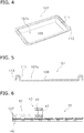
- FIG. 4 is an oblique view of a blank of the microneedles forming sheet.
- FIG. 5 is a cross-sectional view of a blank of the microneedles forming sheet.
- the blank 107 includes a bottom-surface part 109 and side-surface parts 111.
- the bottom-surface part 109 is, for example, a quadrangular, flat, plate-shaped portion.
- the side-surface parts 111 are plate-shaped portions that extend upward from four sides of the bottom-surface part 109 and form a recessed part 107a.
- a folded part 113 is formed over the entire perimeter at upper ends of the side-surface parts 111. In a cross section, the folded part 113 extends toward the outer-perimeter side from the recessed part 107a and further extends downward.
- FIG. 8 is a schematic drawing that illustrates the preheating and forming process. As shown in the figure, a heating chamber 41, a forming apparatus 43, and a cooling chamber 45 are provided in series.
- the blank 107 is preheated prior to being formed.
- the forming apparatus 43 forms the micro-recess parts 13 on the blank 107.
- the cooling chamber 45 the blank 107 is cooled.
- the blank 107 is transported between the apparatuses by a conveyor 46.
- the forming apparatus 43 is an apparatus for forming the plurality of minute micro-recess parts 13 on the bottom-surface part 109 of the blank 107.
- the forming apparatus 43 includes a high-precision press 47 and a pincushion-shaped press die 49 (a micro-spike die).
- the press die 49 includes a press part 51.
- FIG. 7 is a cross-sectional view of the press die.
- the press part 51 has a shape that matches the bottom-surface part 109 of the blank 107, and, on its lower surface, the press part 51 includes a plurality of fabricating projections 53.
- FIG. 8 is a schematic cross-sectional view that shows the state prior to the forming of the blank.
- the blank 107 has already been softened when the press die 49 contacts the bottom-surface part 109.
- the fabricating projections 53 form the plurality of micro-recess parts 13 on the bottom-surface part 109.
- the control of the press is formed by a machine capable of controlling the pressing location, the pressing pressure, the pressing time, and the like with high precision. Although it needs working time, heating and cooling the press die 49 may achieves the previous series of the steps.
- FIG. 9 is a schematic cross-sectional view that shows the state after the forming of the blank.
- each micro-recess part 13 has, for example, a conical shape or a pyramidal shape and is open toward the upper side in the figure.
- a step of supplying the microneedles material 56 to the blank 107 i.e., the whole-forming sheet 3A
- whole microneedle sheet 5A which includes the substrate 10 and a plurality of microneedles 11 formed on the lower surface of the substrate 10 and housed in the plurality of micro-recess parts 13.
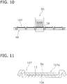
- FIG. 10 is a schematic drawing for explaining a process of dripping a microneedles material onto the microneedles forming sheets.
- a dispenser 55 is provided.
- the dispenser 55 is an apparatus that drips the microneedles material 56 onto the recessed part 107a.
- the microneedles material 56 is, for example, sodium hyaluronate dissolved in a solvent consisting of water, etc. Furthermore, a medium wherein water-soluble macromolecules in addition to water are soluble is selected as the solvent.
- FIG. 11 is a schematic cross-sectional view of the microneedles forming sheet filled with the microneedles material. Furthermore, in the present embodiment, the microneedles material 56 does not penetrate to the interior of the micro-recess parts 13, and consequently air remains in the micro-recess parts 13. In this case, an evacuation process (not shown) may be added.
- FIG. 12 is a schematic drawing for explaining a process of drying the microneedles material.
- a drying furnace 65 is provided.
- the microneedles material 56 for each of the blanks 107 is heated and thereby dried. Thereby, moisture and the solvent agent are evaporated from the microneedles materials 56.
- the microneedles material 56 shrinks because of the drying, and the volume is reduced to the position shown in FIG. 14 .
- FIG. 13 is a schematic cross-sectional view of the microneedles forming sheet filled with the microneedles material prior to the drying process.
- FIG. 14 is a schematic cross-sectional view of the microneedles forming sheet filled with the microneedles material after the drying process.
- FIG. 15 is a cross-sectional view of the microneedle-sheet, forming-and-protecting-structure preform.
- a method of manufacturing the packaging body 1 is explained below, with reference to FIG. 16 to FIG. 23 .
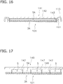
- FIG. 16, FIG. 17 , FIG. 19 , FIG. 21 , and FIG. 22 are schematic cross-sectional views for explaining a process of manufacturing the packaging body from the microneedle-sheet' forming-and-protecting-structure preform.
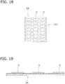
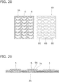
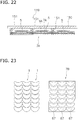
- FIG. 18 , FIG. 20 and FIG. 23 are plan views of the microneedle-sheet's forming-and-protecting-structure preform.
- the preform 101 wherein the whole microneedle sheet 5A has been formed on the bottom-surface part of the whole forming sheet 3A, is prepared.
- a step of punching out the whole microneedle sheet 5A such that a desired plurality of the individual microneedle sheets 5 are formed and then eliminating unnecessary portions is explained below.
- a cutting apparatus 141 is used.
- the cutting apparatus 141 has a press part 142 and a ring-shaped cutting blade 143.
- the cutting blade 143 is provided on a lower surface of the press part 142.
- the cutting blade 143 has a shape that corresponds to the outer perimeter of the bottom-surface part of the whole forming sheet 3A.
- the cutting blade 143 cuts the preform 101 to its lower surface.
- the side-surface part 111 and the folded part 113 of the whole forming sheet 3A are cut off.
- the preform 101 becomes a planar sheet.
- a trimming die such as an etching blade, an engraving blade, or a Thomson blade, can be used as the cutting blade.
- the cutting apparatus 145 includes a press part 146 and a plurality of cutting blades 147. Each cutting blade 147 is provided on a lower surface of the press part 146. Each cutting blade 147 is ring shaped. As shown in FIG. 17 , when the press part 146 is lowered and brought proximate to the preform 101, the cutting blades 147 cut portions of the solidified whole microneedle sheet 5A of the preform 101 to the lower surface, thereby forming the microneedle sheets 5.
- the cutting blades 147 do not reach the lower surface of the whole forming sheet 3A; that is, the cutting blades 147 do not cut the whole forming sheet 3A (performs a half-cut).
- FIG. 19 the plurality of microneedle sheets 5 punched out in shapes corresponding to the plurality of cutting blades 147 are obtained on the whole forming sheet 3A.
- FIG. 19 and the left view in FIG. 20 show a state after waste matter has been removed, and the right view in FIG. 20 shows a waste matter 5B.
- trim remnants 66 which are the remnants remaining after the plurality of microneedle sheets 5 have been eliminated, are formed.
- the whole support body 7A whose plane is a quadrangle corresponding to the whole forming sheet 3A, is fixed to each of the microneedle sheets 5. That is, the whole support body 7A is adhered across the entire surface of the whole forming sheet 3A.
- a whole adhesive layer 9A is provided entirely on a lower surface of the whole support body 7A.
- the whole support body 7A is adhered not only to the microneedle sheets 5 but also to exposed parts of the upper surface of the whole forming sheet 3A. That is, in the step of fixing the whole support body 7A, the whole support body 7A is fixed to the whole forming sheet 3A at the periphery of each individual microneedle sheet 5.
- a cutting apparatus 149 is used.
- the cutting apparatus 149 includes a press part 150 and a plurality of cutting blades 151.
- the cutting blades 151 are provided on a lower surface of the press part 150.
- Each cutting blade 151 is ring shaped and has a diameter larger than that of the cutting blade 147.
- the microneedle sheets 5 are formed in the forming sheet 3 and, furthermore, their state at the time when they are formed is maintained. Specifically, the plurality of microneedles 11 of each microneedle sheet 5 are formed by the plurality of micro-recess parts 13 of the forming sheet 3; subsequently, too, the plurality of microneedles 11 are protected by the plurality of micro-recess parts 13. That is, the plurality of microneedles 11 of each microneedle sheet 5 are reliably protected.
- the packaging body 1 includes the support body 7, which corresponds to the microneedle sheet 5 and is fixed to the forming sheet 3, each individual microneedle sheet 5 is protected.
- the plurality of microneedle sheet packaging bodies 1 are formed all at once by the last article-punching step ( FIG. 22 ). Accordingly, mass production with a small number of processes becomes possible.
- the whole support body 7A is fixed to the whole forming sheet 3A at the periphery of each microneedle sheet 5, and therefore the last article-punching step can create the state wherein the individual support bodies 7 are fixed to the individual forming sheets 3 at the peripheries of the individual microneedle sheets 5. Thereby, the individual microneedle sheets 5 are protected from outside contamination.
- the microneedle sheet 5 is fixed to the forming sheet 3 by the support body 7 and the adhesive layer 9. In so doing, the microneedles 11 are protected when the microneedle sheet packaging body 1 is transported or used.
- the forming sheet 3 functions as a forming die for forming the microneedles 11 of the microneedle sheet 5.
- the forming sheet 3 functions as a protective material that protects the microneedles 11 of each microneedle sheet 5.
- the outer-circumference-side portion farther on the outer side of the outer circumferential edge of the microneedle sheet 5 is entirely enclosed by the structure wherein the support body 7 is fixed to the upper surface of the forming sheet 3 via the adhesive layer 9.
- the present invention is not limited to the abovementioned structure.
- Other structures of the outer-circumference-side portion of the microneedle sheet 5 are explained below.
- microneedle sheet is made into a tabbed shape.
- the microneedle sheet 5 includes a projecting part 10A that extends from the substrate 10 in the sheet-surface direction and is interposed between the support body 7 and the forming sheet 3.
- FIG. 24 is a plan view of the microneedle-sheet packaging body according to the second embodiment of the present invention.
- FIG. 25 is a cross-sectional view taken along line XXV-XXV in FIG. 24 and is a cross-sectional view of the microneedle-sheet packaging body.
- the support body 7 i.e., the adhesive layer 9) does not contact the forming sheet 3 at the location of the projecting part 10A of the microneedle sheet 5, and therefore the bonding strength between the forming sheet 3 and other members is low at that portion of the outer-perimeter part 12. Accordingly, the support body 7 can be easily peeled from the forming sheet 3 by holding and pulling, by hand, an edge (refer to arrow B) of the projecting part 10A of the microneedle sheet 5. In particular, because the microneedle sheet 5 can be directly grasped, the microneedle sheet 5 is reliably peeled from the forming sheet 3.
- the first and second embodiments have the following points in common.
- the microneedle-sheet packaging body (e.g., the packaging body 1) includes the microneedle sheet (e.g., the microneedle sheet 5), the sheet member (e.g., the forming sheet 3), and the support-base-material sheet (e.g., the support body 7).
- the microneedle sheet includes the main body (e.g., the substrate 10), and the plurality of microneedles (e.g., the microneedles 11) formed on the first surface (e.g., the lower surface) of the main body. The sheet member is tightly adhered to the first surface of the main body.
- the sheet member includes the plurality of micro-recess parts (e.g., the micro-recess parts 13) in which the plurality of microneedles is housed.
- the support-base-material sheet is fixed to the second surface (e.g., the upper surface) of the main body of the microneedle sheet and is further fixed to the sheet member around the main body.
- the microneedle sheet is formed in the sheet member (e.g., refer to FIG. 14 ), and the state at the time when the microneedle sheet was formed is maintained.
- the plurality of microneedles of the microneedle sheet are formed by the plurality of micro-recess parts of the sheet member and are also subsequently protected by the plurality of micro-recess parts. That is, the plurality of microneedles of the microneedle sheet are reliably protected.
- the packaging body includes the sheet-shaped base material, which is fixed to the second surface of the main body of the microneedle sheet and is further fixed to the sheet member around the main body (e.g., refer to FIG. 1 ), and therefore the microneedle sheet is reliably protected.
- the present invention can be broadly applied to a microneedle-sheet packaging body including a plurality of microneedles and to a method of manufacturing the same.
Landscapes
- Health & Medical Sciences (AREA)
- Engineering & Computer Science (AREA)
- Life Sciences & Earth Sciences (AREA)
- Dermatology (AREA)
- Animal Behavior & Ethology (AREA)
- Mechanical Engineering (AREA)
- Veterinary Medicine (AREA)
- Public Health (AREA)
- General Health & Medical Sciences (AREA)
- Heart & Thoracic Surgery (AREA)
- Medical Informatics (AREA)
- Anesthesiology (AREA)
- Biomedical Technology (AREA)
- Hematology (AREA)
- Chemical & Material Sciences (AREA)
- Forests & Forestry (AREA)
- Epidemiology (AREA)
- Pharmacology & Pharmacy (AREA)
- Medicinal Chemistry (AREA)
- Composite Materials (AREA)
- Media Introduction/Drainage Providing Device (AREA)
- Packages (AREA)
Abstract
Description
- The present invention relates to a microneedle-sheet packaging body including a plurality of microneedles, and to a method of manufacturing the same.
- A resin sheet having a plurality of minute recessed parts is utilized as, for example, a microneedle-forming die for manufacturing a plurality of microneedles on a microneedle sheet (e.g., refer to Patent Citation 1). Furthermore, one example of a microneedle sheet is a transdermal patch. A transdermal patch is used as one means of noninvasively administering a drug or the like via the body surface of an organism, such as the skin or a mucous membrane. In such a case, the drug is adhered to the microneedles.
- Patent Citation 1: PCT International Publication No.
WO2011/002034 - Each microneedle of the plurality of microneedles of the microneedle sheet has a minute shape that is damaged relatively easily. Furthermore, after a completed microneedle sheet is packaged and ready to be shipped and transported, it is necessary to take measures to ensure that the microneedles do not get damaged. However, an effective measure to protect the microneedles inside the packaging has yet to be proposed.
- An object of the present invention is to protect a plurality of microneedles of a microneedle sheet.
- Aspects of the present invention are explained below as the technical solution. These aspects can be arbitrarily combined as needed.
- According to one aspect of the present invention, a microneedle-sheet packaging body includes a microneedle sheet, a sheet member, and a sheet-shaped base material.
- The microneedle sheet includes a sheet-shaped main body and a plurality of microneedles formed on a first surface of the main body.
- The sheet member is tightly adhered to the first surface of the main body. The sheet member includes a plurality of micro-recess parts in which the plurality of microneedles are housed.
- The sheet-shaped base material is fixed to a second surface of the main body of the microneedle sheet and is further fixed to the sheet member around the main body.
- In this packaging body, the microneedle sheet is formed in the sheet member, and the state at the time when the microneedle sheet was formed is maintained. Specifically, the plurality of microneedles of the microneedle sheet are formed by the plurality of micro-recess parts of the sheet member and is also subsequently protected by the plurality of micro-recess parts. That is, the plurality of microneedles of the microneedle sheet are reliably protected.
- In addition, the packaging body includes the sheet-shaped base material, which is fixed to the second surface of the main body of the microneedle sheet and is further fixed to the sheet member around the main body, and therefore the microneedle sheet is reliably protected.
- The packaging body may further includes an adhesive. The adhesive is fixed to a surface of the sheet-shaped base material on the sheet member side. The adhesive is adhered to the second surface of the main body of the microneedle sheet, and is further adhered to the sheet member around the main body.
- In the packaging body, the sheet-shaped base material is fixed to the microneedle sheet and the sheet member by the adhesive layer. Accordingly, the sheet-shaped base material tends not to peel off of the microneedle sheet and the sheet member. In addition, when the sheet-shaped base material is peeled off of sheet member, together with the microneedle sheet, and then the microneedle sheet can be stuck to the target by using the sheet-shaped base material and the adhesive.
- The peel strength between the sheet-shaped base material and the microneedle sheet may be higher than the peel strength between the microneedle sheet and the sheet member.
- In the packaging body, when the support body is peeled from the forming sheet, the microneedle sheet is reliably peeled from the sheet member.
- The microneedle sheet may include a projecting part. The projecting part extends from the main body in a sheet-surface direction and is interposed between the sheet-shaped base material and the sheet member.
- In this packaging body, the support body does not contact the forming sheet at the location of the projecting part of the microneedle sheet, and therefore the bonding strength between the forming sheet and other members is low at that portion of the outer-perimeter part. Accordingly, the sheet-shaped base material and the microneedle sheet can be easily peeled from the sheet member by holding and pulling, by hand, an edge of the projecting part of the microneedle sheet.
- According to another aspect of the present invention, a microneedle sheet packaging body manufacturing method includes:
- forming a plurality of micro-recess parts on a whole-sheet member;
- supplying a microneedle material to the whole-sheet member such that a whole-microneedle sheet is formed. The whole-microneedle sheet includes a main body and a plurality of microneedles. The microneedles are formed on a first surface of the main body and are disposed inside the plurality of micro-recess parts;
- punching the whole-microneedle sheet such that a desired plurality of individual microneedle sheets are formed, and subsequently eliminating an unnecessary part;
- fixing a whole-sheet-shaped base material to the plurality of individual microneedle sheets; and
- punching, in units of the plurality of individual microneedle sheets, the whole-sheet member and the whole-sheet-shaped base material such that a plurality of the microneedle-sheet packaging bodies are formed, each microneedle-sheet packaging body having the individual microneedle sheet, an individual sheet member, and an individual sheet-shaped base material.
- In the packaging body manufactured by the present manufacturing method, the microneedle sheet is formed in the sheet member, and the state at the time when the microneedle sheet was formed is maintained. Specifically, the plurality of microneedles of the microneedle sheet are formed by the plurality of micro-recess parts of the sheet member and are also subsequently protected by the plurality of micro-recess parts. That is, the plurality of microneedles of the microneedle sheet are reliably protected.
- In addition, because the packaging body includes the individual sheet-shaped base material, which corresponds to individual microneedle sheet and is fixed to the sheet member, each individual microneedle sheet is protected.
- Furthermore, in the present manufacturing method, the plurality of microneedle sheet packaging bodies are formed all at once by the step of punching out the whole sheet member and the sheet-shaped base material in the units of the individual microneedle sheet. Accordingly, mass production with a small number of processes becomes possible.
- In the step of fixing the whole-sheet-shaped base material, the whole-sheet-shaped base material may be fixed to the whole-sheet member around the individual microneedle sheets.
- In the present manufacturing method, the whole support body is fixed to the whole forming sheet at the periphery of each microneedle sheet, and therefore the last article-punching step can create the state wherein the individual sealing sheets are fixed to the individual forming sheets at the peripheries of the individual microneedle sheets. Thereby, the individual microneedle sheets are protected from outside contamination.
- Furthermore, it is possible to roughly handle the materials in a series of the steps, which contributes the improvement on the productivity of the microneedle sheets.
- According to a microneedle-sheet packaging body and a microneedle-sheet packaging body manufacturing method of the present invention, the plurality of microneedles of the microneedle sheet are reliably protected.
-
-
FIG. 1 is a plan view of the microneedle-sheet packaging body according to a first embodiment of the present invention. -
FIG. 2 is a cross-sectional view taken along line II-II inFIG. 1 and is a cross-sectional view of the microneedle-sheet packaging body. -
FIG. 3 is a schematic cross-sectional view of a secondary packaging body of a microneedle sheet. -
FIG. 4 is an oblique view of a blank of a microneedle-forming sheet. -
FIG. 5 is a cross-sectional view of the blank of the microneedle-forming sheet. -
FIG. 6 is a schematic drawing that illustrates a preheating and forming process. -
FIG. 7 is a cross-sectional view of a press die. -
FIG. 8 is a schematic cross-sectional view that shows the state before formation of the blank. -
FIG. 9 is a schematic cross-sectional view that shows the state after the formation of the blank. -
FIG. 10 is a schematic drawing for explaining a process wherein microneedle materials are dripped onto the microneedle-forming sheets. -
FIG. 11 is a schematic cross-sectional view of the microneedle-forming sheet filled with the microneedle material. -
FIG. 12 is a schematic drawing for explaining a process of drying the microneedle materials. -
FIG. 13 is a schematic cross-sectional view of the microneedle-forming sheet filled with the microneedle material before the drying process. -
FIG. 14 is a schematic cross-sectional view of the microneedle-forming sheet filled with the microneedle material after the drying process. -
FIG. 15 is a cross-sectional view of a microneedle sheet, forming-and-protecting-structure preform. -
FIG. 16 is a schematic cross-sectional view for explaining a process of manufacturing the packaging body from the microneedle sheet, forming-and-protecting-structure preform. -
FIG. 17 is a schematic cross-sectional view for explaining a process of manufacturing the packaging body from the microneedle sheet, forming-and-protecting-structure preform. -
FIG. 18 is a plan view of the microneedle-sheet, forming-and-protecting-structure preform. -
FIG. 19 is a schematic cross-sectional view for explaining a process of manufacturing the packaging body from the microneedle-sheet, forming-and-protecting-structure preform. -
FIG. 20 is a plan view of the microneedle-sheet, forming-and-protecting-structure preform. -
FIG. 21 is a schematic cross-sectional view for explaining a process of manufacturing the packaging body from the microneedle-sheet, forming-and-protecting-structure preform. -
FIG. 22 is a schematic cross-sectional view for explaining a process of manufacturing the packaging body from the microneedle-sheet, forming-and-protecting-structure preform. -
FIG. 23 is a plan view of the microneedle-sheet, forming-and-protecting-structure preform. -
FIG. 24 is a plan view of the microneedle-sheet packaging body according to a second embodiment of the present invention. -
FIG. 25 is a cross-sectional view taken along line XXV-XXV inFIG. 24 and is a cross-sectional view of the microneedle-sheet packaging body. - A microneedle-
sheet packaging body 1 according to the present embodiment will be explained, with reference toFIG. 1 and FIG. 2. FIG. 1 is a plan view of the microneedle-sheet packaging body according to the first embodiment of the present invention.FIG. 2 is a cross-sectional view taken along line II-II inFIG. 1 and is a cross-sectional view of the microneedle-sheet packaging body. - The microneedle-
sheet packaging body 1 includes amicroneedle sheet 5, a microneedle-forming sheet 3 (one example of a sheet member; hereinbelow, called a forming sheet 3), and a support body 7 (one example of a sheet-shaped base material). The formingsheet 3 and thesupport body 7 are primary packaging materials that package themicroneedle sheet 5. Thus, thepackaging body 1 is a primary package, the shape of which is a flat, plate-shaped piece. Accordingly, the degrees of freedom of a subsequent secondary package are increased. For example, a vacuum package or a design package is possible. - Furthermore, in the embodiment below, the microneedle sheet housed in the primary packaging material is singular, but a plurality of the microneedle sheets may be housed.
- The
microneedle sheet 5 is a member that is packaged by the primary packaging material, which was discussed above, and is used by being removed from the primary packaging material as needed. Themicroneedle sheet 5 is a sheet-shaped article whereon a plurality ofmicroneedles 11 are formed on one surface. The thickness of themicroneedle sheet 5 is approximately several hundred micrometers. The overall planar shape of themicroneedle sheet 5 is smoothly curved and has a crescent-moon shape, as shown inFIG. 1 . The shape of themicroneedle sheet 5 may be a circle, an ellipse, a triangle, a quadrangle, a square, a magatama (comma), or some other shape. If themicroneedle sheet 5 is, for example, a quadrangle, then one side is approximately several to several tens of millimeters. - The structure of the
microneedle sheet 5 will now be further explained, with reference toFIG. 1 . Themicroneedle sheet 5 includes a sheet-shaped substrate 10 (one example of a sheet-shaped main body) and the plurality of microneedles 11 (one example of microneedles). The plurality ofmicroneedles 11 are formed on a lower surface (one example of a first surface) of thesubstrate 10. Each microneedle 11 has, for example, a conical shape or a pyramidal shape with a height of 10-1,000 µm, wherein the ratio of the cross-sectional diameter, at the base, to the height (cross-sectional-diameter:height) is 1:0.2-1:5 and the aspect ratio (height/cross-sectional diameter) is high. - The
microneedle sheet 5 is a transdermal patch that is used, for example, to administer a drug or the like by being affixed such that it contacts the skin of a person. Specifically, the administration of the drug or the like is promoted by thesubstrate 10 being stuck onto the skin and themicroneedles 11 piercing the skin. - The
microneedle sheet 5 includes, as the principal materials, for example, a water soluble drug and a water-soluble macromolecule, such as hyaluronate, a water-soluble collagen, dextran, chondroitin sulfate, or the like, to which the drug has been added. Furthermore, the water-soluble macromolecule to which a pharmaceutical agent has been added is preferably an in-vivo-soluble, water-soluble macromolecule, for example, an in-vivo-soluble, water-soluble macromolecule such as sodium chondroitin sulfate, hyaluronate, or dextran. - Furthermore, the water-soluble macromolecule is a substance of at least 1 selected from the group consisting of sodium chondroitin sulfate, hyaluronate, a collagen (or a hydrolyzed collagen), gelatin, a glycogen, dextran, dextrin, dextran sulfate, cyclodextrin, chitosan, proteoglycan, pullulan, hydroxypropylcellulose, alginic acid, agarose, glycogen, carboxymethyl cellulose, hydroxyethyl cellulose, hydroxypropylcellulose, polyvinylpyrrolidone, polyvinyl alcohol, and a carboxyvinyl polymer. One of these water-soluble macromolecules may be used alone, or a plurality thereof may be used in combination.
- The
support body 7 is a sheet for supporting themicroneedle sheet 5 and is a material having good air permeability, such as, for example, a nonwoven fabric. Thesupport body 7 is fixed to an upper surface (one example of a second surface) of thesubstrate 10 of themicroneedle sheet 5 and is adhered farther therearound to an upper surface of the formingsheet 3. - More specifically, an adhesive layer 9 (one example of an adhesive) is provided entirely across the lower surface (one example of a sheet-member-side surface) of the
support body 7. Thesupport body 7 is fixed to the upper surface of themicroneedle sheet 5 by theadhesive layer 9. Specifically, theadhesive layer 9 is adhered to the upper surface of thesubstrate 10 of themicroneedle sheet 5 and, furthermore, is adhered to the formingsheet 3 at an outer-perimeter part 12 around thesubstrate 10. Thus, theadhesive layer 9 is provided on a lower surface of thesupport body 7 also at an outer-perimeter part 12, which is further on the outer-perimeter side of themicroneedle sheet 5. Accordingly, thesupport body 7 tends not to peel off of themicroneedle sheet 5 and the formingsheet 3. In addition, after thesupport body 7 has been peeled, together with themicroneedle sheet 5, off of the formingsheet 3, theadhesive layer 9 on the outer-perimeter side is used in sticking thesupport body 7 and themicroneedle sheet 5 to the target. - Furthermore, in
FIG. 2 ,micro-recess parts 13 are formed, on the upper surface of the formingsheet 3, at a portion (corresponding to the outer-perimeter part 12) of the outer-perimeter part of thesupport body 7 at which theadhesive layer 9 is fixed. Thereby, the surface to which theadhesive layer 9 adheres becomes smaller; thereby, the adhesive strength of theadhesive layer 9 is maintained. However, themicro-recess parts 13 do not have to be formed at the abovementioned portion. - Furthermore, the
adhesive layer 9 is composed of, for example, a rubber-based material, an acrylic-based material, a silicone-based material, or a urethane-based material. - The forming
sheet 3 is a member for both forming themicroneedles 11 and protecting themicroneedles 11 after forming. The formingsheet 3 is stuck to the lower surface of themicroneedle sheet 5. In addition, as shown inFIG. 2 , the plurality ofmicro-recess parts 13, which is for forming and housing themicroneedles 11 of themicroneedle sheet 5, is formed on the upper surface of the formingsheet 3. Furthermore, eachmicro-recess part 13 is an indentation that is open toward the upper side and does not pass through themicroneedle sheet 5. - Taking into consideration that the forming
sheet 3 is used as the member that forms the plurality ofmicro-recess parts 13, the formingsheet 3 is composed of, for example, a polyolefin based resin such as polyethylene, polypropylene, and the like. That is, the formingsheet 3 is preferably a hydrophobic sheet wherein the adhesive agent is re-peelable. - When the
support body 7 is to be peeled from the formingsheet 3, the following approaches may become necessary to ensure that themicroneedle sheet 5 reliably follows from the formingsheet 3. Firstly, an adhesive layer with a sufficiently high adhesive strength is selected as theadhesive layer 9. Secondly, the adhesive strength between the formingsheet 3 and themicroneedle sheet 5 is increased by subjecting the surface of the formingsheet 3 to a hydrophilic treatment in advance; however, both the formingsheet 3 and themicroneedle sheet 5 may be made easy to peel by decreasing the extent of that treatment. Furthermore, the first idea and the second idea may be combined. - Furthermore, the bonding strength of both may be increased by aging, in which time is taken to cause the
adhesive layer 9 and themicroneedle sheet 5 to set. - The forming-and-protecting-structure of the microneedle sheet is configured by the
microneedle sheet 5 and the formingsheet 3, which are tightly adhered to one another as discussed above. - Next, a
secondary packaging body 19, which houses thepackaging body 1 that serves as a primary packaging body, will be explained, with reference toFIG. 3 . Thesecondary packaging body 19 includes apackaging member 21 and a sealingsheet 23; thepackaging body 1 is packaged by the two sheets being stuck together. - The
packaging member 21 is a sheet-shaped member and is composed of a common resin material. As shown inFIG. 3 , thepackaging member 21 includes ahousing part 21a for housing thepackaging body 1. Thehousing part 21 a is a recessed part that is formed on an inner side of thepackaging member 21. - The sealing
sheet 23 is a sheet-shaped member that is stuck to the inner-side surface of thepackaging member 21 in order to seal thepackaging body 1 inside thehousing part 21a between the sealingsheet 23 and thepackaging member 21. Specifically, the sealingsheet 23 includes, for example, as a general structure, a surface-resin layer (not shown) and a metal layer (not shown). The surface-resin layer is capable of being printed upon and further functions to protect the metal layer. The metal layer is provided on a lower surface of the surface-resin layer. The metal layer is composed of aluminum or an alloy thereof and has a high degree of moisture proofness. - A bonding layer (not shown) is provided on a surface on the side of the metal layer opposite the surface-resin layer. The bonding layer is for bonding the sealing
sheet 23 to thepackaging member 21. - Thus, the sealing
sheet 23 is stuck to the inner-side surface of thepackaging member 21 in the state wherein the sealingsheet 23 covers thepackaging body 1, and thereby both seal thehousing part 21a. - As shown in
FIG. 3 , thepackaging body 1 is movably disposed inside thepackaging member 21 and the sealingsheet 23. However, thepackaging body 1 may be fixed to thepackaging member 21 by some means. - In the present embodiment, the
packaging body 1 is not positioned inside thesecondary packaging body 19; however, thepackaging body 1 has a structure that protects themicroneedle sheet 5, and therefore the plurality ofmicroneedles 11 of themicroneedle sheet 5 are reliably protected. - When the
packaging body 1 is to be removed from thesecondary packaging body 19, the user peels the sealingsheet 23 from thepackaging member 21, as shown inFIG. 6 , and subsequently thepackaging body 1 is removed from thehousing part 21 a. Thereby, themicroneedle sheet 5, in which the plurality ofmicroneedles 11 are protected by the formingsheet 3, can be obtained. - Next, the user peels the
microneedle sheet 5 from the formingsheet 3. Specifically, the user peels thesupport body 7 from the formingsheet 3 by grasping the outer-perimeter part (refer to arrow A inFIG. 2 ) of thesupport body 7. At this time, themicroneedle sheet 5 separates from the formingsheet 3, that is, themicroneedles 11 separate from themicro-recess parts 13. - As a result, the user becomes able to use the support-body-attached microneedle sheet, which includes the
support body 7 and themicroneedle sheet 5, in accordance with the intended purpose. In the case of a transdermal patch, the support-body-attached microneedle sheet is stuck to the skin of a person. In this case, the outer-perimeter part of thesupport body 7 sticks to the skin via theadhesive layer 9, and themicroneedles 11 of themicroneedle sheet 5 contact the skin. That is, the firstadhesive layer 9 functions as an adhesive portion after the support-body-attached microneedle sheet has been removed. - As discussed above, the object is achieved by just peeling off and then sticking the support-body-attached microneedle sheet, and therefore usage is simple.
- The peel strength between the
support body 7 and themicroneedle sheet 5 is preferably higher than the peel strength between themicroneedle sheet 5 and the formingsheet 3. The reason for that is to make it so that, when thesupport body 7 is peeled from the formingsheet 3, themicroneedle sheet 5 is reliably peeled from the formingsheet 3. The peel strength between thesupport body 7 and themicroneedle sheet 5 is, for example, 4-5 N/20 mm. The peel strength between themicroneedle sheet 5 and the formingsheet 3 is, for example, 1-2 N/20 mm. - A method of manufacturing the microneedle
sheet packaging body 1 will now be explained, with reference toFIG. 4 to FIG. 23 . The plurality of manufacturing processes are explained below. - Hereinbelow, a step of forming a plurality of mirco-
recess parts 13 on the blank 107 (the whole-formingsheet 3A). - First, as shown in
FIG. 4 and FIG. 5 , a blank 107, which will constitute the formingsheet 3, is prepared.FIG. 4 is an oblique view of a blank of the microneedles forming sheet.FIG. 5 is a cross-sectional view of a blank of the microneedles forming sheet. As is clear from the figures, the blank 107 includes a bottom-surface part 109 and side-surface parts 111. The bottom-surface part 109 is, for example, a quadrangular, flat, plate-shaped portion. The side-surface parts 111 are plate-shaped portions that extend upward from four sides of the bottom-surface part 109 and form a recessedpart 107a. Furthermore, a foldedpart 113 is formed over the entire perimeter at upper ends of the side-surface parts 111. In a cross section, the foldedpart 113 extends toward the outer-perimeter side from the recessedpart 107a and further extends downward. - A process of preheating and forming the blank 107 will now be explained, with reference to
FIG. 8 to FIG. 9. FIG. 8 is a schematic drawing that illustrates the preheating and forming process. As shown in the figure, aheating chamber 41, a formingapparatus 43, and acooling chamber 45 are provided in series. - In the
heating chamber 41, the blank 107 is preheated prior to being formed. The formingapparatus 43 forms themicro-recess parts 13 on the blank 107. In the coolingchamber 45, the blank 107 is cooled. The blank 107 is transported between the apparatuses by aconveyor 46. - The forming
apparatus 43 is an apparatus for forming the plurality of minutemicro-recess parts 13 on the bottom-surface part 109 of the blank 107. As shown in the figure, the formingapparatus 43 includes a high-precision press 47 and a pincushion-shaped press die 49 (a micro-spike die). As shown inFIG. 7 , the press die 49 includes apress part 51.FIG. 7 is a cross-sectional view of the press die. Thepress part 51 has a shape that matches the bottom-surface part 109 of the blank 107, and, on its lower surface, thepress part 51 includes a plurality of fabricatingprojections 53. - As shown in
FIG. 8 , prior to the forming work, the bottom-surface part 109 of the blank 107 is flat.FIG. 8 is a schematic cross-sectional view that shows the state prior to the forming of the blank. - Owing to the preheating prior to the forming, the blank 107 has already been softened when the press die 49 contacts the bottom-
surface part 109. As a result, as shown inFIG. 9 , the fabricatingprojections 53 form the plurality ofmicro-recess parts 13 on the bottom-surface part 109. Furthermore, the control of the press is formed by a machine capable of controlling the pressing location, the pressing pressure, the pressing time, and the like with high precision. Although it needs working time, heating and cooling the press die 49 may achieves the previous series of the steps. -
FIG. 9 is a schematic cross-sectional view that shows the state after the forming of the blank. As shown in the figure, eachmicro-recess part 13 has, for example, a conical shape or a pyramidal shape and is open toward the upper side in the figure. - Hereinbelow, a step of supplying the
microneedles material 56 to the blank 107 (i.e., the whole-formingsheet 3A) such thatwhole microneedle sheet 5A, which includes thesubstrate 10 and a plurality ofmicroneedles 11 formed on the lower surface of thesubstrate 10 and housed in the plurality ofmicro-recess parts 13. - Next, the process in which a
microneedles material 56 is supplied to theblanks 107 will be explained, with reference toFIG. 10 to FIG. 11. FIG. 10 is a schematic drawing for explaining a process of dripping a microneedles material onto the microneedles forming sheets. As shown in the figure, adispenser 55 is provided. Thedispenser 55 is an apparatus that drips themicroneedles material 56 onto the recessedpart 107a. Themicroneedles material 56 is, for example, sodium hyaluronate dissolved in a solvent consisting of water, etc. Furthermore, a medium wherein water-soluble macromolecules in addition to water are soluble is selected as the solvent. Thus, by supplying the microneedles material to each bottom-surface part 109, each bottom-surface part 109 is covered by themicroneedles material 56, as shown inFIG. 11. FIG. 11 is a schematic cross-sectional view of the microneedles forming sheet filled with the microneedles material. Furthermore, in the present embodiment, themicroneedles material 56 does not penetrate to the interior of themicro-recess parts 13, and consequently air remains in themicro-recess parts 13. In this case, an evacuation process (not shown) may be added. - Next, a process of drying and hardening the
microneedles material 56 will be explained, with reference toFIG. 12 to FIG. 14 .FIG. 12 is a schematic drawing for explaining a process of drying the microneedles material. As shown in the figure, a dryingfurnace 65 is provided. In the dryingfurnace 65, themicroneedles material 56 for each of theblanks 107 is heated and thereby dried. Thereby, moisture and the solvent agent are evaporated from themicroneedles materials 56. As a result, starting from the state shown inFIG. 13 , themicroneedles material 56 shrinks because of the drying, and the volume is reduced to the position shown inFIG. 14 . In this state, themicroneedles material 56 becomes thewhole microneedle sheet 5A having the plurality ofmicroneedles 11.FIG. 13 is a schematic cross-sectional view of the microneedles forming sheet filled with the microneedles material prior to the drying process.FIG. 14 is a schematic cross-sectional view of the microneedles forming sheet filled with the microneedles material after the drying process. - As a result of the above, as shown in
FIG. 15 , a microneedle-sheet, forming-and-protecting-structure preform 101 (hereinbelow, called a preform 101) is obtained wherein is formed the microneedles material 56 (thewhole microneedle sheet 5A) solidified on the bottom-surface part of the blank 107 (the whole formingsheet 3A).FIG. 15 is a cross-sectional view of the microneedle-sheet, forming-and-protecting-structure preform. - A method of manufacturing the
packaging body 1 is explained below, with reference toFIG. 16 to FIG. 23 . -
FIG. 16, FIG. 17 ,FIG. 19 ,FIG. 21 , andFIG. 22 are schematic cross-sectional views for explaining a process of manufacturing the packaging body from the microneedle-sheet' forming-and-protecting-structure preform.FIG. 18 ,FIG. 20 andFIG. 23 are plan views of the microneedle-sheet's forming-and-protecting-structure preform. - First, the
preform 101, wherein thewhole microneedle sheet 5A has been formed on the bottom-surface part of the whole formingsheet 3A, is prepared. - A step of punching out the
whole microneedle sheet 5A such that a desired plurality of theindividual microneedle sheets 5 are formed and then eliminating unnecessary portions is explained below. - As shown in
FIG. 16 , acutting apparatus 141 is used. Thecutting apparatus 141 has apress part 142 and a ring-shapedcutting blade 143. Thecutting blade 143 is provided on a lower surface of thepress part 142. Thecutting blade 143 has a shape that corresponds to the outer perimeter of the bottom-surface part of the whole formingsheet 3A. As shown inFIG. 16 , when thepress part 142 is lowered and brought proximate to thepreform 101, thecutting blade 143 cuts thepreform 101 to its lower surface. As a result, the side-surface part 111 and the foldedpart 113 of the whole formingsheet 3A are cut off. As a result, thepreform 101 becomes a planar sheet. Furthermore, a trimming die, such as an etching blade, an engraving blade, or a Thomson blade, can be used as the cutting blade. - Next, as shown in
FIG. 17 , acutting apparatus 145 is used. Thecutting apparatus 145 includes apress part 146 and a plurality of cuttingblades 147. Eachcutting blade 147 is provided on a lower surface of thepress part 146. Eachcutting blade 147 is ring shaped. As shown inFIG. 17 , when thepress part 146 is lowered and brought proximate to thepreform 101, thecutting blades 147 cut portions of the solidifiedwhole microneedle sheet 5A of thepreform 101 to the lower surface, thereby forming themicroneedle sheets 5. However, thecutting blades 147 do not reach the lower surface of the whole formingsheet 3A; that is, thecutting blades 147 do not cut the whole formingsheet 3A (performs a half-cut). As a result, as shown inFIG. 19 , the plurality ofmicroneedle sheets 5 punched out in shapes corresponding to the plurality of cuttingblades 147 are obtained on the whole formingsheet 3A.FIG. 19 and the left view inFIG. 20 show a state after waste matter has been removed, and the right view inFIG. 20 shows awaste matter 5B. In thewaste matter 5B,trim remnants 66, which are the remnants remaining after the plurality ofmicroneedle sheets 5 have been eliminated, are formed. - Next, a step of fixing a
whole support body 7A to the plurality ofindividual microneedle sheets 5 will be explained. - As shown in
FIG. 21 , thewhole support body 7A, whose plane is a quadrangle corresponding to the whole formingsheet 3A, is fixed to each of themicroneedle sheets 5. That is, thewhole support body 7A is adhered across the entire surface of the whole formingsheet 3A. A wholeadhesive layer 9A is provided entirely on a lower surface of thewhole support body 7A. - At this time, the
whole support body 7A is adhered not only to themicroneedle sheets 5 but also to exposed parts of the upper surface of the whole formingsheet 3A. That is, in the step of fixing thewhole support body 7A, thewhole support body 7A is fixed to the whole formingsheet 3A at the periphery of eachindividual microneedle sheet 5. - Last, a step will be explained wherein, in units of the
individual microneedle sheet 5, the whole formingsheet 3A and thewhole support body 7A are punched out, thereby forming a plurality of the microneedle-sheet packaging bodies 1, eachpackaging body 1 including anindividual microneedle sheet 5, anindividual forming sheet 3, and anindividual support body 7. - As shown in
FIG. 22 , acutting apparatus 149 is used. Thecutting apparatus 149 includes apress part 150 and a plurality of cuttingblades 151. Thecutting blades 151 are provided on a lower surface of thepress part 150. Eachcutting blade 151 is ring shaped and has a diameter larger than that of thecutting blade 147. When thepress part 150 is lowered and brought proximate to the whole formingsheet 3A and thewhole support body 7A, thecutting blades 151 cut, to the lower surface, the whole formingsheet 3A and thewhole support body 7A at the outer perimeters of theindividual microneedle sheets 5. As a result, as shown on the left side inFIG. 23 , a plurality of thepackaging bodies 1 are obtained. Furthermore, the drawing on the right side ofFIG. 23 iswaste matter 7B. In thewaste matter 7B,trim remnants 67, which are the remnants remaining after the plurality ofpackaging bodies 1 have been cut out, are formed. - In the
packaging body 1 manufactured by this manufacturing method, themicroneedle sheets 5 are formed in the formingsheet 3 and, furthermore, their state at the time when they are formed is maintained. Specifically, the plurality ofmicroneedles 11 of eachmicroneedle sheet 5 are formed by the plurality ofmicro-recess parts 13 of the formingsheet 3; subsequently, too, the plurality ofmicroneedles 11 are protected by the plurality ofmicro-recess parts 13. That is, the plurality ofmicroneedles 11 of eachmicroneedle sheet 5 are reliably protected. - In addition, because the
packaging body 1 includes thesupport body 7, which corresponds to themicroneedle sheet 5 and is fixed to the formingsheet 3, eachindividual microneedle sheet 5 is protected. - Furthermore, in the present manufacturing method, the plurality of microneedle
sheet packaging bodies 1 are formed all at once by the last article-punching step (FIG. 22 ). Accordingly, mass production with a small number of processes becomes possible. - Furthermore, in the present manufacturing method, the
whole support body 7A is fixed to the whole formingsheet 3A at the periphery of eachmicroneedle sheet 5, and therefore the last article-punching step can create the state wherein theindividual support bodies 7 are fixed to theindividual forming sheets 3 at the peripheries of theindividual microneedle sheets 5. Thereby, theindividual microneedle sheets 5 are protected from outside contamination. - Thus, in the state in which the microneedle
sheet packaging body 1 has been completed, themicroneedle sheet 5 is fixed to the formingsheet 3 by thesupport body 7 and theadhesive layer 9. In so doing, themicroneedles 11 are protected when the microneedlesheet packaging body 1 is transported or used. - As discussed above, the forming
sheet 3 functions as a forming die for forming themicroneedles 11 of themicroneedle sheet 5. In addition, the formingsheet 3 functions as a protective material that protects themicroneedles 11 of eachmicroneedle sheet 5. - In the abovementioned first embodiment, the outer-circumference-side portion farther on the outer side of the outer circumferential edge of the
microneedle sheet 5 is entirely enclosed by the structure wherein thesupport body 7 is fixed to the upper surface of the formingsheet 3 via theadhesive layer 9. However, the present invention is not limited to the abovementioned structure. Other structures of the outer-circumference-side portion of themicroneedle sheet 5 are explained below. - An example in which the microneedle sheet is made into a tabbed shape is explained below.
- As shown in
FIG. 24 and FIG. 25 , themicroneedle sheet 5 includes a projectingpart 10A that extends from thesubstrate 10 in the sheet-surface direction and is interposed between thesupport body 7 and the formingsheet 3.FIG. 24 is a plan view of the microneedle-sheet packaging body according to the second embodiment of the present invention.FIG. 25 is a cross-sectional view taken along line XXV-XXV inFIG. 24 and is a cross-sectional view of the microneedle-sheet packaging body. - Specifically, in this packaging body, the support body 7 (i.e., the adhesive layer 9) does not contact the forming
sheet 3 at the location of the projectingpart 10A of themicroneedle sheet 5, and therefore the bonding strength between the formingsheet 3 and other members is low at that portion of the outer-perimeter part 12. Accordingly, thesupport body 7 can be easily peeled from the formingsheet 3 by holding and pulling, by hand, an edge (refer to arrow B) of the projectingpart 10A of themicroneedle sheet 5. In particular, because themicroneedle sheet 5 can be directly grasped, themicroneedle sheet 5 is reliably peeled from the formingsheet 3. - The first and second embodiments have the following points in common.
- The microneedle-sheet packaging body (e.g., the packaging body 1) includes the microneedle sheet (e.g., the microneedle sheet 5), the sheet member (e.g., the forming sheet 3), and the support-base-material sheet (e.g., the support body 7). The microneedle sheet includes the main body (e.g., the substrate 10), and the plurality of microneedles (e.g., the microneedles 11) formed on the first surface (e.g., the lower surface) of the main body. The sheet member is tightly adhered to the first surface of the main body. The sheet member includes the plurality of micro-recess parts (e.g., the micro-recess parts 13) in which the plurality of microneedles is housed. The support-base-material sheet is fixed to the second surface (e.g., the upper surface) of the main body of the microneedle sheet and is further fixed to the sheet member around the main body.
- In this packaging body, the microneedle sheet is formed in the sheet member (e.g., refer to
FIG. 14 ), and the state at the time when the microneedle sheet was formed is maintained. Specifically, the plurality of microneedles of the microneedle sheet are formed by the plurality of micro-recess parts of the sheet member and are also subsequently protected by the plurality of micro-recess parts. That is, the plurality of microneedles of the microneedle sheet are reliably protected. - In addition, the packaging body includes the sheet-shaped base material, which is fixed to the second surface of the main body of the microneedle sheet and is further fixed to the sheet member around the main body (e.g., refer to
FIG. 1 ), and therefore the microneedle sheet is reliably protected. - The above explained one embodiment of the present invention, but the present invention is not limited to the abovementioned embodiment, and it is understood that various modifications may be effected without departing from the gist of the invention. In particular, the embodiments and modified examples written in the present specification can be arbitrarily combined as needed.
- (a) In the abovementioned embodiments, the cutting of the various sheets is performed by a trimming die but may be performed by some other means such as a laser.
- (b) In the abovementioned embodiments, the number of the housing parts of the microneedle-sheet packaging body is one, but there may be a plurality of housing parts.
- The present invention can be broadly applied to a microneedle-sheet packaging body including a plurality of microneedles and to a method of manufacturing the same.
-
- 1
- Packaging body
- 3
- Microneedle-forming sheet
- 3A
- Whole-forming sheet
- 5
- Microneedle sheet
- 5A
- Whole-microneedle sheet
- 7
- Support body
- 7A
- Whole-support member
- 9
- Adhesive layer
- 9A
- Whole-adhesive layer
- 10
- Substrate
- 10A
- Projecting part
- 11
- Microneedle
- 12
- Outer-perimeter part
- 13
- Micro-recess part
- 19
- Primary packaging body
- 21
- Packaging member
- 21a
- Housing part
- 23
- Sealing sheet
- 41
- Heating chamber
- 43
- Forming apparatus
- 45
- Cooling chamber
- 46
- Conveyor
- 47
- High-precision press
- 49
- Press die
- 51
- Press part
- 53
- Fabricating projection
- 55
- Dispenser
- 56
- Microneedle material
- 65
- Drying furnace
- 101
- Forming-and-protecting-structure preform
- 107
- Blank
- 107a
- Recessed part
- 109
- Bottom-surface part
- 111
- Side-surface part
- 113
- Folded part
- 141
- Cutting apparatus
- 142
- Press part
- 143
- Cutting blade
- 145
- Cutting apparatus
- 146
- Press part
- 147
- Cutting blade
- 149
- Cutting apparatus
- 150
- Press part
- 151
- Cutting blade
Claims (6)
- A microneedle-sheet packaging body comprising:a microneedle sheet including a sheet-shaped main body and a plurality of microneedles formed on a first surface of the main body;a sheet member tightly adhered to the first surface of the main body, the sheet member including a plurality of micro-recess parts in which the plurality of microneedles is housed; anda sheet-shaped base material fixed to a second surface of the main body of the microneedle sheet and further fixed to the sheet member around the main body.
- The microneedle-sheet packaging body according to claim 1, further comprising:an adhesive fixed to a surface of the sheet-shaped base material on the sheet member side, the adhesive being adhered to the second surface of the main body of the microneedle sheet, and being further adhered to the sheet member around the main body.
- The microneedle-sheet packaging body according to claim 1 or claim 2, wherein
the peel strength between the sheet-shaped base material and the microneedle sheet is higher than the peel strength between the microneedle sheet and the sheet member. - The microneedle-sheet packaging body according to any one of claims 1 through 3, wherein
the microneedle sheet includes a projecting part, the projecting part extending from the main body in a sheet-surface direction and being interposed between the sheet-shaped base material and the sheet member. - A microneedle-sheet packaging body manufacturing method comprising:forming a plurality of micro-recess parts on a whole-sheet member;supplying a microneedle material to the whole-sheet member such that a whole-microneedle sheet is formed, the whole-microneedle sheet including a main body and a plurality of microneedles formed on a first surface of the main body and disposed inside the plurality of micro-recess parts;punching the whole-microneedle sheet such that a desired plurality of individual microneedle sheets are formed, and subsequently eliminating an unnecessary part;fixing a whole-sheet-shaped base material to the plurality of individual microneedle sheets; andpunching, in units of the plurality of individual microneedle sheets, the whole-sheet member and the whole-sheet-shaped base material such that a plurality of microneedle-sheet packaging bodies are formed, each microneedle-sheet packaging body having the individual microneedle sheet, an individual sheet member, and an individual sheet-shaped base material.
- The microneedle-sheet packaging body manufacturing method according to claim 5, wherein
in the step of fixing the whole-sheet-shaped base material, the whole-sheet-shaped base material is fixed to the whole-sheet member around the individual microneedle sheets.
Applications Claiming Priority (2)
| Application Number | Priority Date | Filing Date | Title |
|---|---|---|---|
| JP2014200410A JP5931155B2 (en) | 2014-09-30 | 2014-09-30 | Package of microneedle sheet and method for manufacturing the same |
| PCT/JP2015/057484 WO2016051819A1 (en) | 2014-09-30 | 2015-03-13 | Packaged microneedle sheet and method for producing same |
Publications (3)
| Publication Number | Publication Date |
|---|---|
| EP3181182A1 true EP3181182A1 (en) | 2017-06-21 |
| EP3181182A4 EP3181182A4 (en) | 2017-08-23 |
| EP3181182B1 EP3181182B1 (en) | 2018-10-24 |
Family
ID=55629879
Family Applications (1)
| Application Number | Title | Priority Date | Filing Date |
|---|---|---|---|
| EP15845576.6A Active EP3181182B1 (en) | 2014-09-30 | 2015-03-13 | Packaged microneedle sheet and method for producing same |
Country Status (7)
| Country | Link |
|---|---|
| US (1) | US9919856B2 (en) |
| EP (1) | EP3181182B1 (en) |
| JP (1) | JP5931155B2 (en) |
| KR (1) | KR102358550B1 (en) |
| CN (1) | CN106687171B (en) |
| TW (1) | TWI630152B (en) |
| WO (1) | WO2016051819A1 (en) |
Families Citing this family (17)
| Publication number | Priority date | Publication date | Assignee | Title |
|---|---|---|---|---|
| JP6327852B2 (en) | 2010-05-04 | 2018-05-23 | コリウム インターナショナル, インコーポレイテッド | Methods and devices for transdermal delivery of parathyroid hormone using microprojection arrays |
| AU2013364053B2 (en) | 2012-12-21 | 2018-08-30 | Corium Pharma Solutions, Inc. | Microarray for delivery of therapeutic agent and methods of use |
| CA2903748C (en) | 2013-03-12 | 2021-11-02 | Corium International, Inc. | Microprojection applicators |
| BR112015022625B1 (en) | 2013-03-15 | 2023-01-31 | Corium, Inc | MICROSTRUCTURE DEVICE FOR DELIVERY OF THERAPEUTIC AGENT |
| WO2016036866A1 (en) | 2014-09-04 | 2016-03-10 | Corium International, Inc. | Microstructure array, methods of making, and methods of use |
| US10857093B2 (en) * | 2015-06-29 | 2020-12-08 | Corium, Inc. | Microarray for delivery of therapeutic agent, methods of use, and methods of making |
| JP2018192177A (en) | 2017-05-22 | 2018-12-06 | コスメディ製薬株式会社 | Water soluble cosmetic sheet-holding film |
| CN107117389A (en) * | 2017-06-03 | 2017-09-01 | 成都五义医疗科技有限公司 | A kind of ladder overcoat packed for puncture outfit and its manufacture method |
| JP6931222B2 (en) | 2017-07-18 | 2021-09-01 | コスメディ製薬株式会社 | Foam support sheet for microneedle array |
| KR102184940B1 (en) * | 2017-11-15 | 2020-12-01 | 주식회사 엘지생활건강 | Apparatus and Process for Continuous Production of Microneedle |
| EP3763415B1 (en) | 2018-03-07 | 2022-03-30 | FUJIFILM Corporation | Method of manufacturing percutaneous absorption sheet |
| JP7666887B2 (en) * | 2018-12-21 | 2025-04-22 | ロレアル | Kit and beauty method using microneedle sheet |
| WO2020144574A1 (en) * | 2019-01-07 | 2020-07-16 | 3M Innovative Properties Company | Packaging for microarrays |
| CN113548511B (en) * | 2021-06-05 | 2023-06-06 | 山东华滋自动化技术股份有限公司 | Micro-needle eye patch processing equipment and processing method thereof |
| WO2023246407A1 (en) * | 2022-06-22 | 2023-12-28 | 苏州悦肤达医疗科技有限公司 | Patch product processing system and patch product processing method |
| KR20240002591A (en) * | 2022-06-29 | 2024-01-05 | 주식회사 페로카 | System and method for manufacturing for micro-needle patch |
| TWI851159B (en) | 2023-04-20 | 2024-08-01 | 達運精密工業股份有限公司 | Microneedle patch and manufacturing method thereof |
Family Cites Families (17)
| Publication number | Priority date | Publication date | Assignee | Title |
|---|---|---|---|---|
| US5423737A (en) * | 1993-05-27 | 1995-06-13 | New Dimensions In Medicine, Inc. | Transparent hydrogel wound dressing with release tab |
| CA2127756C (en) * | 1993-07-19 | 2004-08-31 | Hitoshi Akemi | Package structure of drug-containing pressure-sensitive adhesive sheet |
| US6623457B1 (en) * | 1999-09-22 | 2003-09-23 | Becton, Dickinson And Company | Method and apparatus for the transdermal administration of a substance |
| EP1675536B1 (en) * | 2003-09-17 | 2016-01-20 | BSN medical GmbH | Wound dressing and method for manufacturing the same |
| EP1732640A4 (en) * | 2004-03-12 | 2010-09-01 | Agency Science Tech & Res | METHODS AND MOLDS FOR USE IN THE MANUFACTURE OF MICRO-NEEDLES WITH A SIDE ORIFICE |
| CA2613114C (en) * | 2005-06-27 | 2015-02-24 | 3M Innovative Properties Company | Microneedle cartridge assembly and method of applying |
| DE102007030710A1 (en) | 2007-07-02 | 2009-01-08 | Robert Bosch Gmbh | Device for the storage and administration of active substances and a method for the administration of active substances by means of such a device |
| JP2010094414A (en) * | 2008-10-20 | 2010-04-30 | Kyokko Seiko Co Ltd | Microneedle sheet patch, and method and apparatus for manufacturing the same |
| WO2011002034A1 (en) | 2009-07-01 | 2011-01-06 | 凸版印刷株式会社 | Needle-like material |
| JP5558772B2 (en) * | 2009-10-08 | 2014-07-23 | 東レエンジニアリング株式会社 | STAMPER FOR MICRO NEEDLE SHEET, PROCESS FOR PRODUCING THE SAME, AND METHOD FOR MANUFACTURING MICRO NEEDLE USING THE SAME |
| JP2012055343A (en) | 2010-09-03 | 2012-03-22 | Toray Eng Co Ltd | Microneedle sheet and method for manufacturing the same |
| JP5687170B2 (en) * | 2011-03-30 | 2015-03-18 | コスメディ製薬株式会社 | Microneedle patch storage container |
| JP5903016B2 (en) * | 2012-06-27 | 2016-04-13 | コスメディ製薬株式会社 | Protective release sheet for microneedle patch |
| US20140158572A1 (en) * | 2012-12-07 | 2014-06-12 | Inventagon Llc | Wound Care Dressing |
| JP6111634B2 (en) * | 2012-12-10 | 2017-04-12 | 凸版印刷株式会社 | Needle-like structure manufacturing equipment |
| JP5806701B2 (en) * | 2013-05-07 | 2015-11-10 | 日本写真印刷株式会社 | Method for producing transdermal patch and transdermal patch |
| JP6565917B2 (en) * | 2014-07-30 | 2019-08-28 | 凸版印刷株式会社 | Microneedle unit |
-
2014
- 2014-09-30 JP JP2014200410A patent/JP5931155B2/en active Active
-
2015
- 2015-03-13 EP EP15845576.6A patent/EP3181182B1/en active Active
- 2015-03-13 WO PCT/JP2015/057484 patent/WO2016051819A1/en not_active Ceased
- 2015-03-13 KR KR1020177007744A patent/KR102358550B1/en active Active
- 2015-03-13 US US15/514,761 patent/US9919856B2/en active Active
- 2015-03-13 CN CN201580048386.6A patent/CN106687171B/en active Active
- 2015-04-28 TW TW104113459A patent/TWI630152B/en active
Also Published As
| Publication number | Publication date |
|---|---|
| EP3181182A4 (en) | 2017-08-23 |
| US20170217656A1 (en) | 2017-08-03 |
| US9919856B2 (en) | 2018-03-20 |
| EP3181182B1 (en) | 2018-10-24 |
| TW201612079A (en) | 2016-04-01 |
| JP2016067618A (en) | 2016-05-09 |
| TWI630152B (en) | 2018-07-21 |
| CN106687171A (en) | 2017-05-17 |
| KR20170063591A (en) | 2017-06-08 |
| WO2016051819A1 (en) | 2016-04-07 |
| JP5931155B2 (en) | 2016-06-08 |
| KR102358550B1 (en) | 2022-02-04 |
| CN106687171B (en) | 2020-02-04 |
Similar Documents
| Publication | Publication Date | Title |
|---|---|---|
| US9919856B2 (en) | Microneedle-sheet packaging body and method of manufacturing the same | |
| EP3108924A1 (en) | Packaging body for sheet with conical projections and method for manufacturing same | |
| CN215943725U (en) | Apparatus for producing sheet-like material pieces | |
| US9937336B2 (en) | Method of manufacturing a conical-projections-sheet packaging body | |
| KR20230148800A (en) | A micro-needle array and manufacturing method thereof | |
| CN115674701A (en) | Apparatus and method for producing sheet-like material pieces | |
| KR102592223B1 (en) | A micro-needle array and manufacturing method thereof | |
| CN219361569U (en) | Patch packaging system | |
| TWI857570B (en) | Dissolvable microneedle patch and method to produce dissolvable microneedle patch | |
| KR20210057929A (en) | Apparatus For Medical Dressing Patch | |
| JP6333013B2 (en) | Packing body for cone-shaped projection sheet and method for manufacturing the same | |
| JP7608370B2 (en) | Tool set for manufacturing an adhesive patch, method for manufacturing an adhesive patch, and adhesive laminate | |
| CN111136726B (en) | Concentric die cutting processing technology | |
| CN108582799A (en) | Gauze processing device and gauze processing technology | |
| JPH0446117A (en) | Preparation of plaster with adhesive sheet | |
| JP1720601S (en) | Adhesive skin patch |
Legal Events
| Date | Code | Title | Description |
|---|---|---|---|
| STAA | Information on the status of an ep patent application or granted ep patent |
Free format text: STATUS: THE INTERNATIONAL PUBLICATION HAS BEEN MADE |
|
| PUAI | Public reference made under article 153(3) epc to a published international application that has entered the european phase |
Free format text: ORIGINAL CODE: 0009012 |
|
| STAA | Information on the status of an ep patent application or granted ep patent |
Free format text: STATUS: REQUEST FOR EXAMINATION WAS MADE |
|
| 17P | Request for examination filed |
Effective date: 20170313 |
|
| AK | Designated contracting states |
Kind code of ref document: A1 Designated state(s): AL AT BE BG CH CY CZ DE DK EE ES FI FR GB GR HR HU IE IS IT LI LT LU LV MC MK MT NL NO PL PT RO RS SE SI SK SM TR |
|
| AX | Request for extension of the european patent |
Extension state: BA ME |
|
| A4 | Supplementary search report drawn up and despatched |
Effective date: 20170726 |
|
| RIC1 | Information provided on ipc code assigned before grant |
Ipc: A61M 37/00 20060101AFI20170720BHEP |
|
| DAV | Request for validation of the european patent (deleted) | ||
| DAX | Request for extension of the european patent (deleted) | ||
| RIC1 | Information provided on ipc code assigned before grant |
Ipc: A61M 37/00 20060101AFI20180322BHEP Ipc: B26F 1/40 20060101ALI20180322BHEP |
|
| GRAP | Despatch of communication of intention to grant a patent |
Free format text: ORIGINAL CODE: EPIDOSNIGR1 |
|
| STAA | Information on the status of an ep patent application or granted ep patent |
Free format text: STATUS: GRANT OF PATENT IS INTENDED |
|
| INTG | Intention to grant announced |
Effective date: 20180517 |
|
| GRAS | Grant fee paid |
Free format text: ORIGINAL CODE: EPIDOSNIGR3 |
|
| GRAA | (expected) grant |
Free format text: ORIGINAL CODE: 0009210 |
|
| STAA | Information on the status of an ep patent application or granted ep patent |
Free format text: STATUS: THE PATENT HAS BEEN GRANTED |
|
| AK | Designated contracting states |
Kind code of ref document: B1 Designated state(s): AL AT BE BG CH CY CZ DE DK EE ES FI FR GB GR HR HU IE IS IT LI LT LU LV MC MK MT NL NO PL PT RO RS SE SI SK SM TR |
|
| RAP1 | Party data changed (applicant data changed or rights of an application transferred) |
Owner name: NISSHA CO., LTD. |
|
| REG | Reference to a national code |
Ref country code: CH Ref legal event code: EP |
|
| REG | Reference to a national code |
Ref country code: IE Ref legal event code: FG4D |
|
| REG | Reference to a national code |
Ref country code: AT Ref legal event code: REF Ref document number: 1055969 Country of ref document: AT Kind code of ref document: T Effective date: 20181115 |
|
| REG | Reference to a national code |
Ref country code: DE Ref legal event code: R096 Ref document number: 602015018896 Country of ref document: DE |
|
| REG | Reference to a national code |
Ref country code: NL Ref legal event code: MP Effective date: 20181024 |
|
| REG | Reference to a national code |
Ref country code: LT Ref legal event code: MG4D |
|
| REG | Reference to a national code |
Ref country code: AT Ref legal event code: MK05 Ref document number: 1055969 Country of ref document: AT Kind code of ref document: T Effective date: 20181024 |
|
| PG25 | Lapsed in a contracting state [announced via postgrant information from national office to epo] |
Ref country code: NL Free format text: LAPSE BECAUSE OF FAILURE TO SUBMIT A TRANSLATION OF THE DESCRIPTION OR TO PAY THE FEE WITHIN THE PRESCRIBED TIME-LIMIT Effective date: 20181024 |
|
| PG25 | Lapsed in a contracting state [announced via postgrant information from national office to epo] |
Ref country code: AT Free format text: LAPSE BECAUSE OF FAILURE TO SUBMIT A TRANSLATION OF THE DESCRIPTION OR TO PAY THE FEE WITHIN THE PRESCRIBED TIME-LIMIT Effective date: 20181024 Ref country code: LV Free format text: LAPSE BECAUSE OF FAILURE TO SUBMIT A TRANSLATION OF THE DESCRIPTION OR TO PAY THE FEE WITHIN THE PRESCRIBED TIME-LIMIT Effective date: 20181024 Ref country code: ES Free format text: LAPSE BECAUSE OF FAILURE TO SUBMIT A TRANSLATION OF THE DESCRIPTION OR TO PAY THE FEE WITHIN THE PRESCRIBED TIME-LIMIT Effective date: 20181024 Ref country code: LT Free format text: LAPSE BECAUSE OF FAILURE TO SUBMIT A TRANSLATION OF THE DESCRIPTION OR TO PAY THE FEE WITHIN THE PRESCRIBED TIME-LIMIT Effective date: 20181024 Ref country code: NO Free format text: LAPSE BECAUSE OF FAILURE TO SUBMIT A TRANSLATION OF THE DESCRIPTION OR TO PAY THE FEE WITHIN THE PRESCRIBED TIME-LIMIT Effective date: 20190124 Ref country code: IS Free format text: LAPSE BECAUSE OF FAILURE TO SUBMIT A TRANSLATION OF THE DESCRIPTION OR TO PAY THE FEE WITHIN THE PRESCRIBED TIME-LIMIT Effective date: 20190224 Ref country code: FI Free format text: LAPSE BECAUSE OF FAILURE TO SUBMIT A TRANSLATION OF THE DESCRIPTION OR TO PAY THE FEE WITHIN THE PRESCRIBED TIME-LIMIT Effective date: 20181024 Ref country code: BG Free format text: LAPSE BECAUSE OF FAILURE TO SUBMIT A TRANSLATION OF THE DESCRIPTION OR TO PAY THE FEE WITHIN THE PRESCRIBED TIME-LIMIT Effective date: 20190124 Ref country code: PL Free format text: LAPSE BECAUSE OF FAILURE TO SUBMIT A TRANSLATION OF THE DESCRIPTION OR TO PAY THE FEE WITHIN THE PRESCRIBED TIME-LIMIT Effective date: 20181024 Ref country code: HR Free format text: LAPSE BECAUSE OF FAILURE TO SUBMIT A TRANSLATION OF THE DESCRIPTION OR TO PAY THE FEE WITHIN THE PRESCRIBED TIME-LIMIT Effective date: 20181024 |
|
| PG25 | Lapsed in a contracting state [announced via postgrant information from national office to epo] |
Ref country code: RS Free format text: LAPSE BECAUSE OF FAILURE TO SUBMIT A TRANSLATION OF THE DESCRIPTION OR TO PAY THE FEE WITHIN THE PRESCRIBED TIME-LIMIT Effective date: 20181024 Ref country code: SE Free format text: LAPSE BECAUSE OF FAILURE TO SUBMIT A TRANSLATION OF THE DESCRIPTION OR TO PAY THE FEE WITHIN THE PRESCRIBED TIME-LIMIT Effective date: 20181024 Ref country code: AL Free format text: LAPSE BECAUSE OF FAILURE TO SUBMIT A TRANSLATION OF THE DESCRIPTION OR TO PAY THE FEE WITHIN THE PRESCRIBED TIME-LIMIT Effective date: 20181024 Ref country code: PT Free format text: LAPSE BECAUSE OF FAILURE TO SUBMIT A TRANSLATION OF THE DESCRIPTION OR TO PAY THE FEE WITHIN THE PRESCRIBED TIME-LIMIT Effective date: 20190224 Ref country code: GR Free format text: LAPSE BECAUSE OF FAILURE TO SUBMIT A TRANSLATION OF THE DESCRIPTION OR TO PAY THE FEE WITHIN THE PRESCRIBED TIME-LIMIT Effective date: 20190125 |
|
| REG | Reference to a national code |
Ref country code: DE Ref legal event code: R097 Ref document number: 602015018896 Country of ref document: DE |
|
| PG25 | Lapsed in a contracting state [announced via postgrant information from national office to epo] |
Ref country code: DK Free format text: LAPSE BECAUSE OF FAILURE TO SUBMIT A TRANSLATION OF THE DESCRIPTION OR TO PAY THE FEE WITHIN THE PRESCRIBED TIME-LIMIT Effective date: 20181024 Ref country code: CZ Free format text: LAPSE BECAUSE OF FAILURE TO SUBMIT A TRANSLATION OF THE DESCRIPTION OR TO PAY THE FEE WITHIN THE PRESCRIBED TIME-LIMIT Effective date: 20181024 |
|
| PG25 | Lapsed in a contracting state [announced via postgrant information from national office to epo] |
Ref country code: RO Free format text: LAPSE BECAUSE OF FAILURE TO SUBMIT A TRANSLATION OF THE DESCRIPTION OR TO PAY THE FEE WITHIN THE PRESCRIBED TIME-LIMIT Effective date: 20181024 Ref country code: EE Free format text: LAPSE BECAUSE OF FAILURE TO SUBMIT A TRANSLATION OF THE DESCRIPTION OR TO PAY THE FEE WITHIN THE PRESCRIBED TIME-LIMIT Effective date: 20181024 Ref country code: SM Free format text: LAPSE BECAUSE OF FAILURE TO SUBMIT A TRANSLATION OF THE DESCRIPTION OR TO PAY THE FEE WITHIN THE PRESCRIBED TIME-LIMIT Effective date: 20181024 Ref country code: SK Free format text: LAPSE BECAUSE OF FAILURE TO SUBMIT A TRANSLATION OF THE DESCRIPTION OR TO PAY THE FEE WITHIN THE PRESCRIBED TIME-LIMIT Effective date: 20181024 |
|
| PLBE | No opposition filed within time limit |
Free format text: ORIGINAL CODE: 0009261 |
|
| STAA | Information on the status of an ep patent application or granted ep patent |
Free format text: STATUS: NO OPPOSITION FILED WITHIN TIME LIMIT |
|
| 26N | No opposition filed |
Effective date: 20190725 |
|
| PG25 | Lapsed in a contracting state [announced via postgrant information from national office to epo] |
Ref country code: MC Free format text: LAPSE BECAUSE OF FAILURE TO SUBMIT A TRANSLATION OF THE DESCRIPTION OR TO PAY THE FEE WITHIN THE PRESCRIBED TIME-LIMIT Effective date: 20181024 Ref country code: SI Free format text: LAPSE BECAUSE OF FAILURE TO SUBMIT A TRANSLATION OF THE DESCRIPTION OR TO PAY THE FEE WITHIN THE PRESCRIBED TIME-LIMIT Effective date: 20181024 |
|
| REG | Reference to a national code |
Ref country code: CH Ref legal event code: PL |
|
| PG25 | Lapsed in a contracting state [announced via postgrant information from national office to epo] |
Ref country code: LU Free format text: LAPSE BECAUSE OF NON-PAYMENT OF DUE FEES Effective date: 20190313 |
|
| REG | Reference to a national code |
Ref country code: BE Ref legal event code: MM Effective date: 20190331 |
|
| PG25 | Lapsed in a contracting state [announced via postgrant information from national office to epo] |
Ref country code: LI Free format text: LAPSE BECAUSE OF NON-PAYMENT OF DUE FEES Effective date: 20190331 Ref country code: IE Free format text: LAPSE BECAUSE OF NON-PAYMENT OF DUE FEES Effective date: 20190313 Ref country code: CH Free format text: LAPSE BECAUSE OF NON-PAYMENT OF DUE FEES Effective date: 20190331 |
|
| PG25 | Lapsed in a contracting state [announced via postgrant information from national office to epo] |
Ref country code: BE Free format text: LAPSE BECAUSE OF NON-PAYMENT OF DUE FEES Effective date: 20190331 |
|
| PG25 | Lapsed in a contracting state [announced via postgrant information from national office to epo] |
Ref country code: TR Free format text: LAPSE BECAUSE OF FAILURE TO SUBMIT A TRANSLATION OF THE DESCRIPTION OR TO PAY THE FEE WITHIN THE PRESCRIBED TIME-LIMIT Effective date: 20181024 |
|
| PG25 | Lapsed in a contracting state [announced via postgrant information from national office to epo] |
Ref country code: MT Free format text: LAPSE BECAUSE OF NON-PAYMENT OF DUE FEES Effective date: 20190313 |
|
| PG25 | Lapsed in a contracting state [announced via postgrant information from national office to epo] |
Ref country code: CY Free format text: LAPSE BECAUSE OF FAILURE TO SUBMIT A TRANSLATION OF THE DESCRIPTION OR TO PAY THE FEE WITHIN THE PRESCRIBED TIME-LIMIT Effective date: 20181024 |
|
| PG25 | Lapsed in a contracting state [announced via postgrant information from national office to epo] |
Ref country code: HU Free format text: LAPSE BECAUSE OF FAILURE TO SUBMIT A TRANSLATION OF THE DESCRIPTION OR TO PAY THE FEE WITHIN THE PRESCRIBED TIME-LIMIT; INVALID AB INITIO Effective date: 20150313 |
|
| PG25 | Lapsed in a contracting state [announced via postgrant information from national office to epo] |
Ref country code: MK Free format text: LAPSE BECAUSE OF FAILURE TO SUBMIT A TRANSLATION OF THE DESCRIPTION OR TO PAY THE FEE WITHIN THE PRESCRIBED TIME-LIMIT Effective date: 20181024 |
|
| PGFP | Annual fee paid to national office [announced via postgrant information from national office to epo] |
Ref country code: FR Payment date: 20250325 Year of fee payment: 11 |
|
| PGFP | Annual fee paid to national office [announced via postgrant information from national office to epo] |
Ref country code: IT Payment date: 20250325 Year of fee payment: 11 Ref country code: GB Payment date: 20250321 Year of fee payment: 11 |
|
| PGFP | Annual fee paid to national office [announced via postgrant information from national office to epo] |
Ref country code: DE Payment date: 20260319 Year of fee payment: 12 |