EP3178638A1 - Verfahren zur herstellung eines halbzeugs oder bauteils aus metall und faserverbund - Google Patents
Verfahren zur herstellung eines halbzeugs oder bauteils aus metall und faserverbund Download PDFInfo
- Publication number
- EP3178638A1 EP3178638A1 EP15199680.8A EP15199680A EP3178638A1 EP 3178638 A1 EP3178638 A1 EP 3178638A1 EP 15199680 A EP15199680 A EP 15199680A EP 3178638 A1 EP3178638 A1 EP 3178638A1
- Authority
- EP
- European Patent Office
- Prior art keywords
- prepreg
- forming
- metal carrier
- matrix
- metal
- Prior art date
- Legal status (The legal status is an assumption and is not a legal conclusion. Google has not performed a legal analysis and makes no representation as to the accuracy of the status listed.)
- Withdrawn
Links
- 229910052751 metal Inorganic materials 0.000 title claims abstract description 99
- 239000002184 metal Substances 0.000 title claims abstract description 99
- 238000004519 manufacturing process Methods 0.000 title claims description 6
- 239000002131 composite material Substances 0.000 title description 5
- 239000011159 matrix material Substances 0.000 claims abstract description 59
- 238000000034 method Methods 0.000 claims abstract description 43
- 229920001187 thermosetting polymer Polymers 0.000 claims abstract description 35
- 239000000835 fiber Substances 0.000 claims abstract description 23
- 239000011265 semifinished product Substances 0.000 claims abstract description 13
- 238000010438 heat treatment Methods 0.000 claims abstract description 6
- 238000004132 cross linking Methods 0.000 claims description 16
- 230000008569 process Effects 0.000 claims description 13
- 238000006243 chemical reaction Methods 0.000 claims 2
- 230000000717 retained effect Effects 0.000 claims 1
- 239000004033 plastic Substances 0.000 abstract description 6
- 229920003023 plastic Polymers 0.000 abstract description 6
- 239000010410 layer Substances 0.000 description 20
- 206010040954 Skin wrinkling Diseases 0.000 description 8
- 239000004744 fabric Substances 0.000 description 5
- -1 for example Substances 0.000 description 4
- 238000009499 grossing Methods 0.000 description 4
- 230000037303 wrinkles Effects 0.000 description 4
- 238000005520 cutting process Methods 0.000 description 3
- 230000032798 delamination Effects 0.000 description 3
- 239000000203 mixture Substances 0.000 description 3
- 239000000047 product Substances 0.000 description 3
- 239000004593 Epoxy Substances 0.000 description 2
- XEEYBQQBJWHFJM-UHFFFAOYSA-N Iron Chemical compound [Fe] XEEYBQQBJWHFJM-UHFFFAOYSA-N 0.000 description 2
- 239000004743 Polypropylene Substances 0.000 description 2
- 229910000831 Steel Inorganic materials 0.000 description 2
- HCHKCACWOHOZIP-UHFFFAOYSA-N Zinc Chemical compound [Zn] HCHKCACWOHOZIP-UHFFFAOYSA-N 0.000 description 2
- 239000000853 adhesive Substances 0.000 description 2
- 230000001070 adhesive effect Effects 0.000 description 2
- 238000005452 bending Methods 0.000 description 2
- 238000001816 cooling Methods 0.000 description 2
- 239000010408 film Substances 0.000 description 2
- 239000000463 material Substances 0.000 description 2
- 230000006855 networking Effects 0.000 description 2
- 229920002647 polyamide Polymers 0.000 description 2
- 229920001155 polypropylene Polymers 0.000 description 2
- 239000004814 polyurethane Substances 0.000 description 2
- 229920002635 polyurethane Polymers 0.000 description 2
- 239000011253 protective coating Substances 0.000 description 2
- 230000001681 protective effect Effects 0.000 description 2
- 230000009467 reduction Effects 0.000 description 2
- 230000002787 reinforcement Effects 0.000 description 2
- 239000010959 steel Substances 0.000 description 2
- 230000035882 stress Effects 0.000 description 2
- 238000003856 thermoforming Methods 0.000 description 2
- 229910052725 zinc Inorganic materials 0.000 description 2
- 239000011701 zinc Substances 0.000 description 2
- OKTJSMMVPCPJKN-UHFFFAOYSA-N Carbon Chemical compound [C] OKTJSMMVPCPJKN-UHFFFAOYSA-N 0.000 description 1
- FYYHWMGAXLPEAU-UHFFFAOYSA-N Magnesium Chemical compound [Mg] FYYHWMGAXLPEAU-UHFFFAOYSA-N 0.000 description 1
- 241001676573 Minium Species 0.000 description 1
- 239000004952 Polyamide Substances 0.000 description 1
- 239000004698 Polyethylene Substances 0.000 description 1
- 239000004283 Sodium sorbate Substances 0.000 description 1
- 229910001297 Zn alloy Inorganic materials 0.000 description 1
- 230000009471 action Effects 0.000 description 1
- 239000002318 adhesion promoter Substances 0.000 description 1
- 239000000956 alloy Substances 0.000 description 1
- 229910045601 alloy Inorganic materials 0.000 description 1
- 229910052782 aluminium Inorganic materials 0.000 description 1
- XAGFODPZIPBFFR-UHFFFAOYSA-N aluminium Chemical compound [Al] XAGFODPZIPBFFR-UHFFFAOYSA-N 0.000 description 1
- 239000004760 aramid Substances 0.000 description 1
- 229920003235 aromatic polyamide Polymers 0.000 description 1
- 230000004888 barrier function Effects 0.000 description 1
- 230000015572 biosynthetic process Effects 0.000 description 1
- 229910052799 carbon Inorganic materials 0.000 description 1
- 230000008859 change Effects 0.000 description 1
- 238000004140 cleaning Methods 0.000 description 1
- 229920006018 co-polyamide Polymers 0.000 description 1
- 238000010276 construction Methods 0.000 description 1
- 239000012792 core layer Substances 0.000 description 1
- 230000007797 corrosion Effects 0.000 description 1
- 238000005260 corrosion Methods 0.000 description 1
- 230000003111 delayed effect Effects 0.000 description 1
- 230000001627 detrimental effect Effects 0.000 description 1
- 238000000113 differential scanning calorimetry Methods 0.000 description 1
- 238000005516 engineering process Methods 0.000 description 1
- 150000002118 epoxides Chemical class 0.000 description 1
- 239000003822 epoxy resin Substances 0.000 description 1
- 238000001879 gelation Methods 0.000 description 1
- 239000011521 glass Substances 0.000 description 1
- 230000006872 improvement Effects 0.000 description 1
- 238000009434 installation Methods 0.000 description 1
- 239000011229 interlayer Substances 0.000 description 1
- 229910052742 iron Inorganic materials 0.000 description 1
- 229910052749 magnesium Inorganic materials 0.000 description 1
- 239000011777 magnesium Substances 0.000 description 1
- 230000010355 oscillation Effects 0.000 description 1
- 229920000647 polyepoxide Polymers 0.000 description 1
- 229920000573 polyethylene Polymers 0.000 description 1
- 238000002360 preparation method Methods 0.000 description 1
- 239000011241 protective layer Substances 0.000 description 1
- 230000035484 reaction time Effects 0.000 description 1
- 239000012783 reinforcing fiber Substances 0.000 description 1
- 239000002356 single layer Substances 0.000 description 1
- 239000000126 substance Substances 0.000 description 1
- 230000008646 thermal stress Effects 0.000 description 1
- 239000004634 thermosetting polymer Substances 0.000 description 1
- 239000010409 thin film Substances 0.000 description 1
- 230000036962 time dependent Effects 0.000 description 1
- 238000003466 welding Methods 0.000 description 1
Images


Classifications
-
- B—PERFORMING OPERATIONS; TRANSPORTING
- B29—WORKING OF PLASTICS; WORKING OF SUBSTANCES IN A PLASTIC STATE IN GENERAL
- B29C—SHAPING OR JOINING OF PLASTICS; SHAPING OF MATERIAL IN A PLASTIC STATE, NOT OTHERWISE PROVIDED FOR; AFTER-TREATMENT OF THE SHAPED PRODUCTS, e.g. REPAIRING
- B29C70/00—Shaping composites, i.e. plastics material comprising reinforcements, fillers or preformed parts, e.g. inserts
- B29C70/04—Shaping composites, i.e. plastics material comprising reinforcements, fillers or preformed parts, e.g. inserts comprising reinforcements only, e.g. self-reinforcing plastics
- B29C70/28—Shaping operations therefor
- B29C70/40—Shaping or impregnating by compression not applied
- B29C70/50—Shaping or impregnating by compression not applied for producing articles of indefinite length, e.g. prepregs, sheet moulding compounds [SMC] or cross moulding compounds [XMC]
- B29C70/52—Pultrusion, i.e. forming and compressing by continuously pulling through a die
- B29C70/525—Component parts, details or accessories; Auxiliary operations
- B29C70/528—Heating or cooling
-
- B—PERFORMING OPERATIONS; TRANSPORTING
- B21—MECHANICAL METAL-WORKING WITHOUT ESSENTIALLY REMOVING MATERIAL; PUNCHING METAL
- B21D—WORKING OR PROCESSING OF SHEET METAL OR METAL TUBES, RODS OR PROFILES WITHOUT ESSENTIALLY REMOVING MATERIAL; PUNCHING METAL
- B21D22/00—Shaping without cutting, by stamping, spinning, or deep-drawing
- B21D22/02—Stamping using rigid devices or tools
- B21D22/022—Stamping using rigid devices or tools by heating the blank or stamping associated with heat treatment
-
- B—PERFORMING OPERATIONS; TRANSPORTING
- B21—MECHANICAL METAL-WORKING WITHOUT ESSENTIALLY REMOVING MATERIAL; PUNCHING METAL
- B21D—WORKING OR PROCESSING OF SHEET METAL OR METAL TUBES, RODS OR PROFILES WITHOUT ESSENTIALLY REMOVING MATERIAL; PUNCHING METAL
- B21D22/00—Shaping without cutting, by stamping, spinning, or deep-drawing
- B21D22/20—Deep-drawing
- B21D22/22—Deep-drawing with devices for holding the edge of the blanks
-
- B—PERFORMING OPERATIONS; TRANSPORTING
- B21—MECHANICAL METAL-WORKING WITHOUT ESSENTIALLY REMOVING MATERIAL; PUNCHING METAL
- B21D—WORKING OR PROCESSING OF SHEET METAL OR METAL TUBES, RODS OR PROFILES WITHOUT ESSENTIALLY REMOVING MATERIAL; PUNCHING METAL
- B21D35/00—Combined processes according to or processes combined with methods covered by groups B21D1/00 - B21D31/00
- B21D35/002—Processes combined with methods covered by groups B21D1/00 - B21D31/00
- B21D35/005—Processes combined with methods covered by groups B21D1/00 - B21D31/00 characterized by the material of the blank or the workpiece
- B21D35/006—Blanks having varying thickness, e.g. tailored blanks
-
- B—PERFORMING OPERATIONS; TRANSPORTING
- B21—MECHANICAL METAL-WORKING WITHOUT ESSENTIALLY REMOVING MATERIAL; PUNCHING METAL
- B21D—WORKING OR PROCESSING OF SHEET METAL OR METAL TUBES, RODS OR PROFILES WITHOUT ESSENTIALLY REMOVING MATERIAL; PUNCHING METAL
- B21D35/00—Combined processes according to or processes combined with methods covered by groups B21D1/00 - B21D31/00
- B21D35/002—Processes combined with methods covered by groups B21D1/00 - B21D31/00
- B21D35/008—Processes combined with methods covered by groups B21D1/00 - B21D31/00 involving vibration, e.g. ultrasonic
-
- B—PERFORMING OPERATIONS; TRANSPORTING
- B29—WORKING OF PLASTICS; WORKING OF SUBSTANCES IN A PLASTIC STATE IN GENERAL
- B29C—SHAPING OR JOINING OF PLASTICS; SHAPING OF MATERIAL IN A PLASTIC STATE, NOT OTHERWISE PROVIDED FOR; AFTER-TREATMENT OF THE SHAPED PRODUCTS, e.g. REPAIRING
- B29C70/00—Shaping composites, i.e. plastics material comprising reinforcements, fillers or preformed parts, e.g. inserts
- B29C70/04—Shaping composites, i.e. plastics material comprising reinforcements, fillers or preformed parts, e.g. inserts comprising reinforcements only, e.g. self-reinforcing plastics
- B29C70/06—Fibrous reinforcements only
- B29C70/08—Fibrous reinforcements only comprising combinations of different forms of fibrous reinforcements incorporated in matrix material, forming one or more layers, and with or without non-reinforced layers
- B29C70/088—Fibrous reinforcements only comprising combinations of different forms of fibrous reinforcements incorporated in matrix material, forming one or more layers, and with or without non-reinforced layers and with one or more layers of non-plastics material or non-specified material, e.g. supports
-
- B—PERFORMING OPERATIONS; TRANSPORTING
- B29—WORKING OF PLASTICS; WORKING OF SUBSTANCES IN A PLASTIC STATE IN GENERAL
- B29C—SHAPING OR JOINING OF PLASTICS; SHAPING OF MATERIAL IN A PLASTIC STATE, NOT OTHERWISE PROVIDED FOR; AFTER-TREATMENT OF THE SHAPED PRODUCTS, e.g. REPAIRING
- B29C70/00—Shaping composites, i.e. plastics material comprising reinforcements, fillers or preformed parts, e.g. inserts
- B29C70/04—Shaping composites, i.e. plastics material comprising reinforcements, fillers or preformed parts, e.g. inserts comprising reinforcements only, e.g. self-reinforcing plastics
- B29C70/28—Shaping operations therefor
- B29C70/40—Shaping or impregnating by compression not applied
-
- B—PERFORMING OPERATIONS; TRANSPORTING
- B29—WORKING OF PLASTICS; WORKING OF SUBSTANCES IN A PLASTIC STATE IN GENERAL
- B29C—SHAPING OR JOINING OF PLASTICS; SHAPING OF MATERIAL IN A PLASTIC STATE, NOT OTHERWISE PROVIDED FOR; AFTER-TREATMENT OF THE SHAPED PRODUCTS, e.g. REPAIRING
- B29C70/00—Shaping composites, i.e. plastics material comprising reinforcements, fillers or preformed parts, e.g. inserts
- B29C70/88—Shaping composites, i.e. plastics material comprising reinforcements, fillers or preformed parts, e.g. inserts characterised primarily by possessing specific properties, e.g. electrically conductive or locally reinforced
- B29C70/882—Shaping composites, i.e. plastics material comprising reinforcements, fillers or preformed parts, e.g. inserts characterised primarily by possessing specific properties, e.g. electrically conductive or locally reinforced partly or totally electrically conductive, e.g. for EMI shielding
- B29C70/885—Shaping composites, i.e. plastics material comprising reinforcements, fillers or preformed parts, e.g. inserts characterised primarily by possessing specific properties, e.g. electrically conductive or locally reinforced partly or totally electrically conductive, e.g. for EMI shielding with incorporated metallic wires, nets, films or plates
-
- B—PERFORMING OPERATIONS; TRANSPORTING
- B32—LAYERED PRODUCTS
- B32B—LAYERED PRODUCTS, i.e. PRODUCTS BUILT-UP OF STRATA OF FLAT OR NON-FLAT, e.g. CELLULAR OR HONEYCOMB, FORM
- B32B15/00—Layered products comprising a layer of metal
- B32B15/04—Layered products comprising a layer of metal comprising metal as the main or only constituent of a layer, which is next to another layer of the same or of a different material
- B32B15/08—Layered products comprising a layer of metal comprising metal as the main or only constituent of a layer, which is next to another layer of the same or of a different material of synthetic resin
- B32B15/092—Layered products comprising a layer of metal comprising metal as the main or only constituent of a layer, which is next to another layer of the same or of a different material of synthetic resin comprising epoxy resins
-
- B—PERFORMING OPERATIONS; TRANSPORTING
- B32—LAYERED PRODUCTS
- B32B—LAYERED PRODUCTS, i.e. PRODUCTS BUILT-UP OF STRATA OF FLAT OR NON-FLAT, e.g. CELLULAR OR HONEYCOMB, FORM
- B32B15/00—Layered products comprising a layer of metal
- B32B15/04—Layered products comprising a layer of metal comprising metal as the main or only constituent of a layer, which is next to another layer of the same or of a different material
- B32B15/08—Layered products comprising a layer of metal comprising metal as the main or only constituent of a layer, which is next to another layer of the same or of a different material of synthetic resin
- B32B15/095—Layered products comprising a layer of metal comprising metal as the main or only constituent of a layer, which is next to another layer of the same or of a different material of synthetic resin comprising polyurethanes
-
- B—PERFORMING OPERATIONS; TRANSPORTING
- B32—LAYERED PRODUCTS
- B32B—LAYERED PRODUCTS, i.e. PRODUCTS BUILT-UP OF STRATA OF FLAT OR NON-FLAT, e.g. CELLULAR OR HONEYCOMB, FORM
- B32B15/00—Layered products comprising a layer of metal
- B32B15/14—Layered products comprising a layer of metal next to a fibrous or filamentary layer
-
- B—PERFORMING OPERATIONS; TRANSPORTING
- B32—LAYERED PRODUCTS
- B32B—LAYERED PRODUCTS, i.e. PRODUCTS BUILT-UP OF STRATA OF FLAT OR NON-FLAT, e.g. CELLULAR OR HONEYCOMB, FORM
- B32B15/00—Layered products comprising a layer of metal
- B32B15/18—Layered products comprising a layer of metal comprising iron or steel
-
- B—PERFORMING OPERATIONS; TRANSPORTING
- B32—LAYERED PRODUCTS
- B32B—LAYERED PRODUCTS, i.e. PRODUCTS BUILT-UP OF STRATA OF FLAT OR NON-FLAT, e.g. CELLULAR OR HONEYCOMB, FORM
- B32B15/00—Layered products comprising a layer of metal
- B32B15/20—Layered products comprising a layer of metal comprising aluminium or copper
-
- B—PERFORMING OPERATIONS; TRANSPORTING
- B32—LAYERED PRODUCTS
- B32B—LAYERED PRODUCTS, i.e. PRODUCTS BUILT-UP OF STRATA OF FLAT OR NON-FLAT, e.g. CELLULAR OR HONEYCOMB, FORM
- B32B19/00—Layered products comprising a layer of natural mineral fibres or particles, e.g. asbestos, mica
- B32B19/02—Layered products comprising a layer of natural mineral fibres or particles, e.g. asbestos, mica the layer of fibres or particles being impregnated or embedded in a plastic substance
-
- B—PERFORMING OPERATIONS; TRANSPORTING
- B32—LAYERED PRODUCTS
- B32B—LAYERED PRODUCTS, i.e. PRODUCTS BUILT-UP OF STRATA OF FLAT OR NON-FLAT, e.g. CELLULAR OR HONEYCOMB, FORM
- B32B19/00—Layered products comprising a layer of natural mineral fibres or particles, e.g. asbestos, mica
- B32B19/04—Layered products comprising a layer of natural mineral fibres or particles, e.g. asbestos, mica next to another layer of the same or of a different material
- B32B19/041—Layered products comprising a layer of natural mineral fibres or particles, e.g. asbestos, mica next to another layer of the same or of a different material of metal
-
- B—PERFORMING OPERATIONS; TRANSPORTING
- B32—LAYERED PRODUCTS
- B32B—LAYERED PRODUCTS, i.e. PRODUCTS BUILT-UP OF STRATA OF FLAT OR NON-FLAT, e.g. CELLULAR OR HONEYCOMB, FORM
- B32B27/00—Layered products comprising a layer of synthetic resin
- B32B27/06—Layered products comprising a layer of synthetic resin as the main or only constituent of a layer, which is next to another layer of the same or of a different material
- B32B27/08—Layered products comprising a layer of synthetic resin as the main or only constituent of a layer, which is next to another layer of the same or of a different material of synthetic resin
-
- B—PERFORMING OPERATIONS; TRANSPORTING
- B32—LAYERED PRODUCTS
- B32B—LAYERED PRODUCTS, i.e. PRODUCTS BUILT-UP OF STRATA OF FLAT OR NON-FLAT, e.g. CELLULAR OR HONEYCOMB, FORM
- B32B27/00—Layered products comprising a layer of synthetic resin
- B32B27/38—Layered products comprising a layer of synthetic resin comprising epoxy resins
-
- B—PERFORMING OPERATIONS; TRANSPORTING
- B32—LAYERED PRODUCTS
- B32B—LAYERED PRODUCTS, i.e. PRODUCTS BUILT-UP OF STRATA OF FLAT OR NON-FLAT, e.g. CELLULAR OR HONEYCOMB, FORM
- B32B27/00—Layered products comprising a layer of synthetic resin
- B32B27/40—Layered products comprising a layer of synthetic resin comprising polyurethanes
-
- B—PERFORMING OPERATIONS; TRANSPORTING
- B32—LAYERED PRODUCTS
- B32B—LAYERED PRODUCTS, i.e. PRODUCTS BUILT-UP OF STRATA OF FLAT OR NON-FLAT, e.g. CELLULAR OR HONEYCOMB, FORM
- B32B3/00—Layered products comprising a layer with external or internal discontinuities or unevennesses, or a layer of non-planar shape; Layered products comprising a layer having particular features of form
- B32B3/26—Layered products comprising a layer with external or internal discontinuities or unevennesses, or a layer of non-planar shape; Layered products comprising a layer having particular features of form characterised by a particular shape of the outline of the cross-section of a continuous layer; characterised by a layer with cavities or internal voids ; characterised by an apertured layer
-
- B—PERFORMING OPERATIONS; TRANSPORTING
- B32—LAYERED PRODUCTS
- B32B—LAYERED PRODUCTS, i.e. PRODUCTS BUILT-UP OF STRATA OF FLAT OR NON-FLAT, e.g. CELLULAR OR HONEYCOMB, FORM
- B32B5/00—Layered products characterised by the non- homogeneity or physical structure, i.e. comprising a fibrous, filamentary, particulate or foam layer; Layered products characterised by having a layer differing constitutionally or physically in different parts
- B32B5/02—Layered products characterised by the non- homogeneity or physical structure, i.e. comprising a fibrous, filamentary, particulate or foam layer; Layered products characterised by having a layer differing constitutionally or physically in different parts characterised by structural features of a fibrous or filamentary layer
- B32B5/024—Woven fabric
-
- B—PERFORMING OPERATIONS; TRANSPORTING
- B32—LAYERED PRODUCTS
- B32B—LAYERED PRODUCTS, i.e. PRODUCTS BUILT-UP OF STRATA OF FLAT OR NON-FLAT, e.g. CELLULAR OR HONEYCOMB, FORM
- B32B5/00—Layered products characterised by the non- homogeneity or physical structure, i.e. comprising a fibrous, filamentary, particulate or foam layer; Layered products characterised by having a layer differing constitutionally or physically in different parts
- B32B5/02—Layered products characterised by the non- homogeneity or physical structure, i.e. comprising a fibrous, filamentary, particulate or foam layer; Layered products characterised by having a layer differing constitutionally or physically in different parts characterised by structural features of a fibrous or filamentary layer
- B32B5/026—Knitted fabric
-
- B—PERFORMING OPERATIONS; TRANSPORTING
- B32—LAYERED PRODUCTS
- B32B—LAYERED PRODUCTS, i.e. PRODUCTS BUILT-UP OF STRATA OF FLAT OR NON-FLAT, e.g. CELLULAR OR HONEYCOMB, FORM
- B32B5/00—Layered products characterised by the non- homogeneity or physical structure, i.e. comprising a fibrous, filamentary, particulate or foam layer; Layered products characterised by having a layer differing constitutionally or physically in different parts
- B32B5/02—Layered products characterised by the non- homogeneity or physical structure, i.e. comprising a fibrous, filamentary, particulate or foam layer; Layered products characterised by having a layer differing constitutionally or physically in different parts characterised by structural features of a fibrous or filamentary layer
- B32B5/028—Net structure, e.g. spaced apart filaments bonded at the crossing points
-
- B—PERFORMING OPERATIONS; TRANSPORTING
- B32—LAYERED PRODUCTS
- B32B—LAYERED PRODUCTS, i.e. PRODUCTS BUILT-UP OF STRATA OF FLAT OR NON-FLAT, e.g. CELLULAR OR HONEYCOMB, FORM
- B32B7/00—Layered products characterised by the relation between layers; Layered products characterised by the relative orientation of features between layers, or by the relative values of a measurable parameter between layers, i.e. products comprising layers having different physical, chemical or physicochemical properties; Layered products characterised by the interconnection of layers
- B32B7/04—Interconnection of layers
-
- B—PERFORMING OPERATIONS; TRANSPORTING
- B32—LAYERED PRODUCTS
- B32B—LAYERED PRODUCTS, i.e. PRODUCTS BUILT-UP OF STRATA OF FLAT OR NON-FLAT, e.g. CELLULAR OR HONEYCOMB, FORM
- B32B7/00—Layered products characterised by the relation between layers; Layered products characterised by the relative orientation of features between layers, or by the relative values of a measurable parameter between layers, i.e. products comprising layers having different physical, chemical or physicochemical properties; Layered products characterised by the interconnection of layers
- B32B7/04—Interconnection of layers
- B32B7/12—Interconnection of layers using interposed adhesives or interposed materials with bonding properties
-
- B—PERFORMING OPERATIONS; TRANSPORTING
- B32—LAYERED PRODUCTS
- B32B—LAYERED PRODUCTS, i.e. PRODUCTS BUILT-UP OF STRATA OF FLAT OR NON-FLAT, e.g. CELLULAR OR HONEYCOMB, FORM
- B32B2255/00—Coating on the layer surface
- B32B2255/06—Coating on the layer surface on metal layer
-
- B—PERFORMING OPERATIONS; TRANSPORTING
- B32—LAYERED PRODUCTS
- B32B—LAYERED PRODUCTS, i.e. PRODUCTS BUILT-UP OF STRATA OF FLAT OR NON-FLAT, e.g. CELLULAR OR HONEYCOMB, FORM
- B32B2255/00—Coating on the layer surface
- B32B2255/20—Inorganic coating
- B32B2255/205—Metallic coating
-
- B—PERFORMING OPERATIONS; TRANSPORTING
- B32—LAYERED PRODUCTS
- B32B—LAYERED PRODUCTS, i.e. PRODUCTS BUILT-UP OF STRATA OF FLAT OR NON-FLAT, e.g. CELLULAR OR HONEYCOMB, FORM
- B32B2255/00—Coating on the layer surface
- B32B2255/28—Multiple coating on one surface
-
- B—PERFORMING OPERATIONS; TRANSPORTING
- B32—LAYERED PRODUCTS
- B32B—LAYERED PRODUCTS, i.e. PRODUCTS BUILT-UP OF STRATA OF FLAT OR NON-FLAT, e.g. CELLULAR OR HONEYCOMB, FORM
- B32B2260/00—Layered product comprising an impregnated, embedded, or bonded layer wherein the layer comprises an impregnation, embedding, or binder material
- B32B2260/02—Composition of the impregnated, bonded or embedded layer
- B32B2260/021—Fibrous or filamentary layer
-
- B—PERFORMING OPERATIONS; TRANSPORTING
- B32—LAYERED PRODUCTS
- B32B—LAYERED PRODUCTS, i.e. PRODUCTS BUILT-UP OF STRATA OF FLAT OR NON-FLAT, e.g. CELLULAR OR HONEYCOMB, FORM
- B32B2260/00—Layered product comprising an impregnated, embedded, or bonded layer wherein the layer comprises an impregnation, embedding, or binder material
- B32B2260/04—Impregnation, embedding, or binder material
- B32B2260/046—Synthetic resin
-
- B—PERFORMING OPERATIONS; TRANSPORTING
- B32—LAYERED PRODUCTS
- B32B—LAYERED PRODUCTS, i.e. PRODUCTS BUILT-UP OF STRATA OF FLAT OR NON-FLAT, e.g. CELLULAR OR HONEYCOMB, FORM
- B32B2262/00—Composition or structural features of fibres which form a fibrous or filamentary layer or are present as additives
- B32B2262/02—Synthetic macromolecular fibres
- B32B2262/0261—Polyamide fibres
- B32B2262/0269—Aromatic polyamide fibres
-
- B—PERFORMING OPERATIONS; TRANSPORTING
- B32—LAYERED PRODUCTS
- B32B—LAYERED PRODUCTS, i.e. PRODUCTS BUILT-UP OF STRATA OF FLAT OR NON-FLAT, e.g. CELLULAR OR HONEYCOMB, FORM
- B32B2262/00—Composition or structural features of fibres which form a fibrous or filamentary layer or are present as additives
- B32B2262/10—Inorganic fibres
-
- B—PERFORMING OPERATIONS; TRANSPORTING
- B32—LAYERED PRODUCTS
- B32B—LAYERED PRODUCTS, i.e. PRODUCTS BUILT-UP OF STRATA OF FLAT OR NON-FLAT, e.g. CELLULAR OR HONEYCOMB, FORM
- B32B2262/00—Composition or structural features of fibres which form a fibrous or filamentary layer or are present as additives
- B32B2262/10—Inorganic fibres
- B32B2262/101—Glass fibres
-
- B—PERFORMING OPERATIONS; TRANSPORTING
- B32—LAYERED PRODUCTS
- B32B—LAYERED PRODUCTS, i.e. PRODUCTS BUILT-UP OF STRATA OF FLAT OR NON-FLAT, e.g. CELLULAR OR HONEYCOMB, FORM
- B32B2262/00—Composition or structural features of fibres which form a fibrous or filamentary layer or are present as additives
- B32B2262/10—Inorganic fibres
- B32B2262/106—Carbon fibres, e.g. graphite fibres
-
- B—PERFORMING OPERATIONS; TRANSPORTING
- B32—LAYERED PRODUCTS
- B32B—LAYERED PRODUCTS, i.e. PRODUCTS BUILT-UP OF STRATA OF FLAT OR NON-FLAT, e.g. CELLULAR OR HONEYCOMB, FORM
- B32B2270/00—Resin or rubber layer containing a blend of at least two different polymers
-
- B—PERFORMING OPERATIONS; TRANSPORTING
- B32—LAYERED PRODUCTS
- B32B—LAYERED PRODUCTS, i.e. PRODUCTS BUILT-UP OF STRATA OF FLAT OR NON-FLAT, e.g. CELLULAR OR HONEYCOMB, FORM
- B32B2307/00—Properties of the layers or laminate
- B32B2307/50—Properties of the layers or laminate having particular mechanical properties
-
- B—PERFORMING OPERATIONS; TRANSPORTING
- B32—LAYERED PRODUCTS
- B32B—LAYERED PRODUCTS, i.e. PRODUCTS BUILT-UP OF STRATA OF FLAT OR NON-FLAT, e.g. CELLULAR OR HONEYCOMB, FORM
- B32B2307/00—Properties of the layers or laminate
- B32B2307/70—Other properties
- B32B2307/732—Dimensional properties
-
- B—PERFORMING OPERATIONS; TRANSPORTING
- B32—LAYERED PRODUCTS
- B32B—LAYERED PRODUCTS, i.e. PRODUCTS BUILT-UP OF STRATA OF FLAT OR NON-FLAT, e.g. CELLULAR OR HONEYCOMB, FORM
- B32B2307/00—Properties of the layers or laminate
- B32B2307/70—Other properties
- B32B2307/752—Corrosion inhibitor
-
- B—PERFORMING OPERATIONS; TRANSPORTING
- B32—LAYERED PRODUCTS
- B32B—LAYERED PRODUCTS, i.e. PRODUCTS BUILT-UP OF STRATA OF FLAT OR NON-FLAT, e.g. CELLULAR OR HONEYCOMB, FORM
- B32B2457/00—Electrical equipment
- B32B2457/08—PCBs, i.e. printed circuit boards
Definitions
- the invention relates to a method for producing a semifinished product or component, in which a metal support with at least one prepreg, comprising a thermally crosslinkable thermosetting matrix with continuous fibers, pre-crosslinked by thermosetting the prepreg by thermosetting and the occupied with the pre-crosslinked prepreg metal support a semi-finished product or component is formed.
- the invention therefore has the task of improving a method of the type described in terms of its simplicity, applications and also in its reproducibility. In addition, a method with a low cycle time is to be made possible.
- the invention achieves this object by converting the matrix into a state of viscosity which follows its viscosity minimum during precrosslinking of the thermosetting matrix of the prepreg and, before it reaches its gelling point, the prepreg is shaped together with the metal support.
- the matrix is converted into a state of viscosity which follows its viscosity minimum and the prepreg is shaped together with the metal support before it reaches its gelling point, not only a plastic deformation on the metal support in its fiber-reinforced regions can be allowed Reproducibility of the process can be significantly improved.
- the prepreg located in this state can namely allow the forming radii relative movements between its Endfläfasen and the metal carrier. Thus, even tight bending radii can be followed on the blank, without having to expect a break or delamination.
- the inventive method is therefore particularly versatile.
- the compacting of the matrix material with the fiber structure of the continuous fibers can be considerably improved by the joint forming.
- the comparatively short application of force, in particular pressurization, during forming can be used to reduce the porosity in the fiber composite - whereby the laminate quality can be increased and the risk of delamination of the fiber reinforcement on the sheet metal blank can be further reduced. Therefore, according to the invention, the reproducibility of the process can be considerably improved by transferring the matrix to a state of viscosity following its viscosity minimum and forming the prepreg together with the metal support before reaching the gelation point of the matrix. In addition, it is possible to provide a particularly fast procedure with low cycle time by the common forming of prepreg and metal carrier.
- the process according to the invention does not require any elaborate comparison with other known processes for the production of fiber composite semifinished products or components and / or complex handling technology - which means not only a reduction in the cost of the inventive method but also an improvement in its reproducibility.
- the metal carrier can consist of sheets with an iron, aluminum or magnesium material, of a light metal or the like or of alloys of these.
- a metal support a steel sheet with or without a protective layer, for example, zinc-based, distinguished.
- the thermosetting plastic matrix, a combination with inorganic or organic reinforcing fibers, such. As glass, basalt, carbon or aramid may have.
- the covering of the metal carrier with multiple prepregs side by side and a stacking of prepregs (single-layer or multi-layer) on the metal support is conceivable.
- the fibers contained in the prepreg may be present as a pure unidirectional layer.
- thermoset plastic matrix may also comprise modified thermosetting polymer blends, which preferably consist of non-necessarily crosslinked epoxide and polyurethane phase phases.
- modified thermosetting polymer blends which preferably consist of non-necessarily crosslinked epoxide and polyurethane phase phases.
- Known percentage compositions of such a PU-epoxy blend are, for example, 5 to 25 parts of primary polyurethane phase in the surrounding epoxy matrix.
- a rheometer for example an Anton Paar MCR 301 viscometer under oscillation
- thermoset matrix In order to reduce the risk of undesired squeezing out of the prepreg of the thermoset matrix heated above the viscosity minium during forming, it can be provided that the degree of crosslinking of the thermoset matrix is adjusted to 4 to 15% before forming.
- the degree of crosslinking of the thermoset matrix is adjusted to 20 to 45% during the forming process.
- the risk of unwanted squeezing of the thermoset matrix during forming is additionally reducible.
- the compressive stress on the prepreg during forming can provide optimum conditions for achieving increased laminate quality of the prepreg. In addition, this may also serve the adhesion between the material partners.
- thermoset matrix It may be particularly advantageous if the degree of crosslinking of the thermoset matrix is adjusted to 25 to 40% during the forming process.
- thermosetting matrix is heated to 120 to 220 ° C during forming, the cross-linking can be accelerated - whereby the forming can be done faster or the cycle time of the process can be reduced.
- thermosetting matrix is heated to 150 to 180.degree.
- the temperature of the forming tool may differ from the temperature of the prepreg or its matrix. It is also conceivable that the tools of the forming tool have different temperatures in order to specifically temper the metal carrier area-specifically or to set a temperature gradient in the laminate.
- the cycle times for forming can be reduced if the prepreg is cured without pressure after the common forming with the metal carrier - and due to which the forming tool can be removed very quickly.
- an intermediate layer is applied to the metal carrier before or during the occupation of the metal carrier with the prepreg, via which the prepreg is bonded to the metal carrier, on the one hand improves the adhesive strength, on the other hand can also be compensated for thermal stresses.
- This intermediate layer should be applied over the full area at least in that area of the metal carrier which is also covered with prepreg.
- the layer thickness of the intermediate layer may preferably be from 50 .mu.m to 1000 .mu.m, layer thicknesses of from 80 .mu.m to 700 .mu.m are preferred.
- Thicker layers preferably layer thicknesses of 500 .mu.m to 1000 .mu.m, can be distinguished by the fact that they additionally offer protection against corrosion (barrier layer).
- the processing time ie the reaction time is relevant - which is especially important for shorter cycle times.
- intermediate layers based on polyethylene, polypropylene and / or polyamide core or interlayers based on co-polyamide can be particularly well suited. These can be, for example, systems from Nolax, namely products Cox 391, Cox 422, Cox 435, systems from Evonik, namely the product Vestamelt X1333-P1 or systems from Hexcel, namely the products TGA25.01 A or DLS 1857.
- the matrix of the prepreg is subjected to a compressive force during forming.
- a compressive load can be generated, for example, when the prepreg-formed and formed as a sheet metal carrier is formed by deep drawing or stretch forming.
- the metal support may be formed, for example, by cross-splitting a metal strip, also formed as a flat sheet or board.
- a wrinkling or a fiber distortion on the prepreg can be prevented if the prepreg is partially held down during forming on the metal support and thereby fixed there to the metal support.
- the prepreg can be admitted according to the respective orientation of its continuous fibers mobility in other directions.
- the forming tool has a plurality of such hold-downs.
- Such a hold-down can also be created by a local tool gap reduction, for example, between the die and stamp.
- the risk of wrinkling or fiber distortion can be further reduced if the prepreg during forming in the forming engagement with sequentially acting segments or groups of segments of a die and / or a punch of a forming tool.
- a delayed action of the forming tool can be achieved on the prepreg - whereby the prepreg can follow the plastic deformation of the metal carrier improved.
- any wrinkles on the prepreg or air pockets contained therein can be pressed out in an elegant manner in the direction of the edge of the metal carrier.
- the forming tool can thus be dispensed with, for example, a subsequent smoothing of the prepreg.
- Such a metal carrier can be formed, for example, by longitudinal gaps of a metal strip, also formed as a flat slit strip to avoid draping.
- Wrinkling and / or blistering on the prepreg which may form in the course of roll profiling, can be successfully counteracted if, after the roll profiling of the metal carrier, the prepreg is pressed against the metal carrier again. This can be done using pairs of roles, for example.
- the metal support 3 is on a flat side, which is to be occupied with prepreg 6, previously possibly still cleaned and / or chemically pretreated - which, however, is not shown in detail.
- the metal carrier 3 is covered with a plurality of prepregs 6 by means of a robot 7.
- the metal support 3 may possibly be preheated for this purpose.
- a robot 8 For cutting the prepreg 6, for example, a robot 8 with cutting devices not shown in detail, for example, with an ultrasound-excited Cutting edge, provided, which separates this from a pre-impregnated with plastic matrix, wound into a roll 9 tissue / scrim / braid / knitted fabric, etc. (FVK).
- the fabric / scrim / braid / knitted fabric / knit, etc. 10 made of continuous fibers is already impregnated in the exemplary embodiment with a thermally crosslinkable, thermosetting matrix.
- the metal carrier 3 is covered with preconditioned prepregs 6, for example, automated, as in Fig. 1 represented, and / or by hand.
- These prepregs 6 may already be preconditioned in their dimensions, in density, in the number of layers and / or with an intermediate layer, for example stacked in a stack.
- the thus occupied metal carrier 3 is irradiated by means of a heat source 11 - and thus set the networking of the matrix targeted.
- This crosslinking of the matrix is carried out without pressure and by using a pre-impregnated fabric / scrim / mesh / knitted / knitted fabric, etc. 10 by heating it from 80 ° C to 200 ° C, preferably 100 ° C to 180 ° C, with a heating rate of 1 to 40 ° C / min, preferably 5 to 25 ° C / min, carried out - in order to adjust a degree of crosslinking ⁇ before forming from 4 to 15%.
- IR or NIR radiator heat source 11 for example, a continuous furnace is conceivable, but this is not shown in detail in the embodiment.
- the occupied metal carrier 3 is introduced into a forming tool 12 and formed.
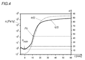
- this forming takes place in coordination with the precrosslinking of the thermoset matrix of the prepreg 6, as is the case with the prepreg Fig. 4 can be seen.
- this matrix is converted into a state of viscosity ⁇ following its viscosity minimum ⁇ min and, before it reaches its gelling point Pc, it is shaped together with the metal carrier 3 with the aid of the forming tool 12.
- the Forming tool 12 is transferred for this purpose from an open to a closed position.
- the endless chamfers of the prepreg 6 are still movable relative to the metal carrier 3 in the prepreg 6.
- the matrix of the prepreg 6 is in a state of viscosity ⁇ following its viscosity minimum ⁇ min , as a result of which breakage of the continuous fibers or delamination of the fiber reinforcement on the metal carrier 3 does not occur during forming - as described in US Pat Fig. 2 can be seen closer.
- According to the invention is thus a common deformation with bending radii 13 on the metal support 3 in its free of prepreg 6 areas as well as in his occupied with prepreg 6 areas 14 possible.
- Fig. 4 refers to a following fiber composite material:
- Metal support Sheet steel: sheet thickness 0.81 mm laminate: unidirectional, four layers of prepreg prepreg: Continuous fibers with a fiber content of 57% in the matrix Thickness: 0.22 mm
- Intermediate layer 100 ⁇ m polypropylene
- the degree of crosslinking ⁇ of the matrix was determined by differential scanning calorimetry (DSC).
- thermoforming tool 15 is shown as a forming tool 12, so as to reshape or deep-draw the occupied metal carrier 3.
- the metal support 3 is subjected to a combined stretching and deep drawing with a forming tool, not shown.
- thermoset matrix of the prepreg 6 In order to reduce the risk of squeezing out of the thermoset matrix of the prepreg 6 during forming, this matrix is pre-crosslinked to 4 to 15% as mentioned before the forming tool 12 exerts forces on the prepreg 6 - which is the same as in FIG Fig. 1 shown occurs when the forming tool 12 is transferred from its open to its closed position.
- the degree of crosslinking ⁇ of the matrix is set from 4 to 15% before forming to 20 to 45% during forming, which limits 20 to 45% of the lines Fig. 4 were drawn.
- the component 2 is removed from the forming tool 12.
- the removal of the component 2 from the forming tool 12 takes place at or after reaching the gelling point of the respective matrix. This allows for a similar laminate quality on prepreg 6 a greatly reduced cycle time over known methods and ensures the sufficient intrinsic stability of the matrix system with the fibers.
- thermoset matrix is held at a temperature of 120 to 220 ° C during forming to remove the component 2 earlier the forming tool by faster networking and thus be able to shorten the process .
- a temperature of 150 to 180 ° C could be distinguished.
- this has an electric heater 16
- the die 17 and punch 18 of the forming tool 12 is heated.
- a heater for the hold-down 19 is not shown, but this is just as conceivable.
- a temperature gradient in the matrix or prepreg 6 can be set by regions with different temperatures in order to be able to set physical and chemical parameters-such as adhesive strength, viscosity state, etc., precisely.
- the component 2 is removed from the forming tool 12 and the matrix of the prepreg 6 outside the forming tool 12 further pressure-less hardened - with a further heat source 20, the after Fig. 1 can be seen.
- a further heat source 20 for this purpose, among other things, an unillustrated continuous furnace is conceivable again.
- this further curing is carried out by the heat source 20 at a temperature of 100 to 200 degrees Celsius (° C) in order to reduce, for example, residual stresses by the subsequent cooling at room temperature. In many cases, a temperature of 120 to 150 ° C could be a temperature of 100 to 200 degrees Celsius (° C) in order to reduce, for example, residual stresses by the subsequent cooling at room temperature. In many cases, a temperature of 120 to 150 ° C could
- the metal support 3 to be coated also has, among other things, a protective coating 21, for example a zinc or zinc alloy layer, on top of it - like this one Fig. 2 can be recognized.
- a protective coating 21 for example a zinc or zinc alloy layer
- an intermediate layer 22 is applied in the prepreg 6 over the entire area.
- This intermediate layer 22 is produced by applying a polyamide-based adhesion promoter to the metal carrier 3.
- the prepreg 6 can be attached to the metal support 3 extremely tight and low tension.
- the prepreg 6 is partially held down during forming on the metal support 3 and fixed in this way there on the metal support 3 - as in the Fig. 2 is indicated.
- the segment 23 of the die 17 presses the prepreg 6 against the metal carrier 3, which is stabilized by a counter holder 24 of the die 17, for example, in this area. Wrinkling or fiber distortion on the prepreg is avoided in this way.
- the engagement region 27 is segmented toward the edge 28 of the metal carrier 3 in the course of the forming process extended.
- a kind of smoothing of the prepreg during forming can be made possible via the segmented forming tool 12, which precludes the formation of wrinkles and air inclusions on the prepreg reproducible.
- Fig. 3 illustrated alternative sequence for the method 101 according to the invention are shown for forming a component 102 stands 115 of a roll forming as forming tool 112.
- a provided on a support 121 prepreg 6 which is disproportionately shown in terms of sizes, applied to a designed as a slit strip 104 metal carrier 103 - which slit strip 104 is generated from a coil, not shown by longitudinal columns / parts.
- the metal carrier 103 is performed together with carrier 121 and prepreg 6 by a pressure roller pair 122, after which the carrier 121 remains on the metal carrier 103.
- the prepreg 6 may be covered on the upper and / or lower side with a protective film 123. Before the application of the prepreg 6, at least the protective film 123, on the side of the prepreg 6 facing the carrier 121, is pulled off and rolled up. Subsequently, the metal carrier 103 is covered with the prepreg 6.
- thermosetting matrix is converted into a viscosity state ⁇ following its viscosity minimum ⁇ min and the prepreg 6 is also here before it reaches the gelling point Pc of its matrix together with the metal carrier 103 by cooperating rollers 124 of the frames 115 of the roll forming.
- the deformed metal carrier 103 is cut to form components 102.
- cut-to-length components 102 may still be subjected to another pressureless cross-linking, which is not shown in detail.
- the roll forming system After a standard strip preparation, which is carried out with the aid of a strip welding system 127 and a leveling machine 128, the roll forming system still has a feed punch 129, with which the metal carrier 103 is punched and / or embossed. Subsequently, the belt moves into the belt cleaning 130, where preferably those surfaces to be provided with prepregs 6 are pre-cleaned. After the loop pit 131, prepreg 6, for example in strip form, is applied. Moreover, in the Fig. 3 to recognize that after reshaping a calibration 132 takes place and then an optional wrinkle smoothing 133 is performed.
- This wrinkle smoothing 133 can take place, for example, with the aid of opposing rollers, between which the roll-profiled metal carrier 103 is guided, and the prepreg 6 is pressed against the metal carrier 103 again. Subsequently, the crosslinking can be initiated via a further heat source 134.
Landscapes
- Engineering & Computer Science (AREA)
- Mechanical Engineering (AREA)
- Chemical & Material Sciences (AREA)
- Composite Materials (AREA)
- Textile Engineering (AREA)
- Physics & Mathematics (AREA)
- Thermal Sciences (AREA)
- Moulding By Coating Moulds (AREA)
- Reinforced Plastic Materials (AREA)
- Casting Or Compression Moulding Of Plastics Or The Like (AREA)
- Laminated Bodies (AREA)
Abstract
Es wird ein Verfahren (1, 101) zur Herstellung eines Halbzeugs oder Bauteils (2, 102) gezeigt, bei dem ein Metallträger (3, 103) mit mindestens einem Prepreg (6), aufweisend eine thermisch vernetzbare, duroplastische Matrix mit Endlosfasern, belegt, die duroplastische Matrix des Prepreg (6) durch Erwärmen vorvernetzt und der mit dem vorvernetzten Prepreg (6) belegte Metallträger (3, 103) zu einem Halbzeug oder Bauteil (2, 102) umgeformt wird. Um plastischer Formänderung an faserverstärkten Bereichen des Metallträgers (3, 103) zu ermöglichen, wird vorgeschlagen, dass beim Vorvernetzen der duroplastischen Matrix des Prepregs (6) dessen Matrix in einen ihrem Viskositätsminimum (·min) nachfolgenden Viskositätszustand (·) übergeführt und noch vor Erreichen ihres Gelierpunkts (Pc) das Prepreg (6) gemeinsam mit dem Metallträger (3, 103) umgeformt wird.
Description
- Die Erfindung betrifft ein Verfahren zur Herstellung eines Halbzeugs oder Bauteils, bei dem ein Metallträger mit mindestens einem Prepreg, aufweisend eine thermisch vernetzbare, duroplastische Matrix mit Endlosfasern, belegt, die duroplastische Matrix des Prepregs durch Erwärmen vorvernetzt und der mit dem vorvernetzten Prepreg belegte Metallträger zu einem Halbzeug oder Bauteil umgeformt wird.
- Um einen Metallträger, nämlich einen Blechzuschnitt bzw. eine Blechplatine, verstärkt mit Prepregs, die eine duroplastische Matrix mit Endlosfasern aufweisen, möglichst beschädigungsfrei einem Umformverfahren, insbesondere Tiefziehen, unterwerfen zu können, ist es aus dem Stand der Technik bekannt (
WO2013/153229A1 ), die plastischen Verformungen am Metallträger in die beschichtungsfreien Bereiche des Metallträgers zu verlagern. Demnach bestehen beschichtungsfreie Bereiche am Halbzeug oder Bauteil, was solche FVK-verstärkten Halbzeuge bzw. Bauteile hinsichtlich ihres Leichtbaupotentials und damit ihrer Anwendungsmöglichkeiten einschränkt. Hinzu kommt, dass durch diese Flächenbeschränkung auch die Faserlänge der Prepregs eingeschränkt wird, was zu reduzierter Steifigkeit und Festigkeit führen kann. Zudem zeigte sich bei Halbzeugen oder Bauteilen, die aus Blechzuschnitten mit drucklos bis zur Blockfestigkeit ausgehärteten Prepregs tiefgezogen wurden, die Tendenz zur Delamination und/oder zu einer erhöhten Porosität im endvernetzten Faserverbundmaterial - was unter anderem die Reproduzierbarkeit des Verfahrens beeinträchtigt. - Die Erfindung hat sich daher die Aufgabe gestellt, ein Verfahren der eingangs geschilderten Art hinsichtlich seiner Einfachheit, Anwendungsmöglichkeiten und auch in seiner Reproduzierbarkeit zu verbessern. Zudem soll ein Verfahren mit geringer Zykluszeit ermöglicht werden.
- Die Erfindung löst die gestellte Aufgabe dadurch, dass beim Vorvernetzen der duroplastischen Matrix des Prepregs dessen Matrix in einen ihrem Viskositätsminimum nachfolgenden Viskositätszustand übergeführt und noch vor Erreichen ihres Gelierpunkts das Prepreg gemeinsam mit dem Metallträger umgeformt wird.
- Wird beim Vorvernetzen der duroplastischen Matrix des Prepregs dessen Matrix in einen ihrem Viskositätsminimum nachfolgenden Viskositätszustand übergeführt und noch vor Erreichen ihres Gelierpunkts das Prepreg gemeinsam mit dem Metallträger umgeformt wird, kann dadurch nicht nur eine plastische Formänderung am Metallträger in dessen faserverstärkten Bereichen zugelassen, sondern auch die Reproduzierbarkeit des Verfahrens deutlich verbessert werden. Das sich in diesem Zustand befindliche Prepreg kann nämlich den Umformradien entsprechende, relative Bewegungen zwischen seinen Endlosfasen und dem Metallträger zulassen. Somit kann selbst engen Biegeradien am Blechzuschnitt gefolgt werden, ohne mit einem Bruch oder einer Delamination rechnen zu müssen. Das erfindungsgemäße Verfahren ist daher besonders vielseitig anwendbar. Überraschend konnte zudem erreicht werden, dass durch das gemeinsame Umformen das Kompaktieren des Matrixmaterials mit der Faserstruktur der Endlosfasern erheblich verbessert werden kann. Die vergleichsweise kurze Kraftbeaufschlagung, insbesondere Druckbeaufschlagung, beim Umformen kann genutzt werden, die Porosität im Faserverbund zu verringern - womit die Laminatqualität erhöhbar und die Gefahr einer Delamination der Faserverstärkung am Blechzuschnitt weiter reduzierbar ist. Erfindungsgemäß kann daher durch das Überführen der Matrix in einen ihrem Viskositätsminimum nachfolgenden Viskositätszustand und dem Umformen des Prepregs gemeinsam mit dem Metallträger noch vor Erreichen des Gelierpunkts der Matrix die Reproduzierbarkeit des Verfahren erheblich verbessert werden. Zudem ist es möglich, durch das gemeinsame Umformen von Prepreg und Metallträger einen besonders schnellen Verfahrensablauf mit geringer Zykluszeit zu Verfügung zu stellen. Außerdem bedarf es das erfindungsgemäße Verfahren im Vergleich mit anderen bekannten Verfahren zur Herstellung von Faserverbund-Halbzeugen oder -Bauteilen keiner aufwendigen und/oder komplex handhabbaren Anlagentechnik - was neben einer Reduzierung der Kosten für das erfindungsgemäße Verfahren auch eine Verbesserung seiner Reproduzierbarkeit bedeutet.
- Im Allgemeinen wird erwähnt, dass der Metallträger aus Blechen mit einem Eisen-, Aluminium- oder Magnesiumwerkstoff, aus einem Leichtmetall oder dergleichen bzw. aus Legierungen aus diesen bestehen kann. Als Metallträger kann sich ein Stahlblech mit oder ohne Schutzschicht, beispielsweise auf Zinkbasis, auszeichnen. Im Allgemeinen wird weiter erwähnt, dass die duroplastische Kunststoffmatrix eine Kombination mit anorganischen oder organischen Verstärkungsfasern, wie z. B. Glas, Basalt, Kohlenstoff oder Aramid aufweisen kann. Zudem ist das Belegen des Metallträgers mit mehreren Prepregs nebeneinander als auch eine Stapelung von Prepregs (einlagig oder mehrlagig) auf dem Metallträger denkbar. Die im Prepreg enthaltenen Fasern können als reine unidirektionale Schicht vorliegen. Damit kann mit mehrlagigen Prepregs ein unidirektionales oder multidirektionales Laminat am Metallträger geschaffen werden.
Außerdem wird im Allgemeinen festgehalten, dass eine duroplastische Kunststoffmatrix auch modifizierte duroplastische Polymerblends aufweisen kann, welche vorzugsweise aus nicht zwangsweise miteinander vernetzten Phasen aus Epoxid- und Polyurethanphasen bestehen. Bekannte prozentuale Zusammensetzungen solch eines PU-Epoxy-Blends sind, beispielsweise 5 bis 25 Teile primärer Polyurethanphase in umgebender Epoxymatrix.
Im Allgemeinen wird weiter erwähnt, dass zur Bestimmung der Viskosität der Matrix unter anderem ein Rheometer (beispielsweise ein Viskosimeter Anton Paar MCR 301 unter Oszillation) herangezogen werden kann. - Um die Gefahr eines unerwünschten Ausquetschens aus dem Prepreg der über dem Viskositätsminium erwärmten duroplastischen Matrix beim Umformen zu reduzieren, kann vorgesehen sein, dass vor dem Umformen der Vernetzungsgrad der duroplastischen Matrix auf 4 bis 15 % eingestellt wird.
- Besonders vorteilhaft kann sein, wenn beim Umformen der Vernetzungsgrad der duroplastischen Matrix auf 20 bis 45 % eingestellt wird. Dadurch ist nämlich die Gefahr eines unerwünschten Ausquetschens der duroplastischen Matrix beim Umformen zusätzlich reduzierbar. Auch kann bei solch einem Vernetzungsgrad die Druckbelastung auf das Prepreg beim Umformen für optimale Bedingungen zur Erreichung einer erhöhten Laminatqualität des Prepregs sorgen. Zudem kann dies auch der Haftfestigkeit zwischen den Werkstoffpartnern dienlich sein.
- Besonders vorteilhaft kann sein, wenn beim Umformen der Vernetzungsgrad der duroplastischen Matrix auf 25 bis 40 % eingestellt wird.
- Wird beim Umformen die duroplastische Matrix auf 120 bis 220°C erwärmt, kann die Vernetzung beschleunigt werden - womit das Umformen schneller erfolgen kann bzw. die Zykluszeit des Verfahrens verringert werden.
- Besonders vorteilhaft kann sein, wenn beim Umformen die duroplastische Matrix auf 150 bis 180°C erwärmt wird.
- Ein unerwünschtes Abkühlen des erwärmten Prepregs - und somit eine für das erfindungsgemäße Verfahren nachteilige Änderung der Temperatur - kann verhindert werden, wenn das Umformwerkzeug erwärmt und der Metallträger mit dem erwärmten Umformwerkzeug umgeformt wird. Auf diese Weise ist die Reproduzierbarkeit des Verfahrens weiter erhöhbar. Es wird festgehalten, dass zu diesem Zweck die Temperatur des Umformwerkzeugs von der Temperatur des Prepregs bzw. seiner Matrix abweichen kann. Vorstellbar ist weiter, dass die Werkzeuge des Umformwerkzeugs unterschiedliche Temperaturen aufweisen, um den Metallträger gezielt bereichsspezifisch zu temperieren oder einen Temperaturgradienten im Laminat einzustellen.
- Die Zykluszeiten zum Umformen können reduziert werden, wenn das Prepreg nach dem gemeinsamen Umformen mit dem Metallträger drucklos gehärtet wird - und aufgrund dessen das Umformwerkzeug besonders rasch wieder entfernt werden kann.
- Dadurch, dass vor dem oder beim Belegen des Metallträgers mit dem Prepreg eine Zwischenschicht auf den Metallträger aufgebracht wird, über die das Prepreg an den Metallträger angebunden wird, kann einerseits die Haftfestigkeit verbessert, andererseits auch ausgleichend auf thermische Spannungen eingewirkt werden. Diese Zwischenschicht sollte zumindest in jenem Bereich des Metallträgers vollflächig aufgebracht werden, der auch mit Prepreg belegt wird.
Die Schichtdicke der Zwischenschicht kann bevorzugt von 50 µm bis 1000 µm betragen, bevorzugt sind Schichtdicken von 80 µm bis 700 µm. Dickere Schichten, bevorzugt Schichtdicken von 500 µm bis 1000 µm können sich dadurch auszeichnen, dass diese zudem einen Schutz vor Korrosion bieten (Sperrschicht). Bei Anwendungen mit hohen Steifigkeitsanforderungen sind dünne Filme bevorzugt (bevorzugt <150 µm). Des Weiteren ist die Verarbeitungszeit, d. h. die Reaktionszeit relevant - was vor allem bei kürzeren Zykluszeiten zu beachten ist. Hierbei hat sich gezeigt, dass Zwischenschichten auf Basis von Polyethylen, Polypropylen und/oder mit Polyamid-Kern oder auch Zwischenschichten auf Co-Polyamid-Basis besonders gut geeignet sein können. Dies können beispielsweise Systeme der Firma Nolax, nämlich Produkte Cox 391, Cox 422, Cox 435, Systeme der Firma Evonik, nämlich das Produkt Vestamelt X1333-P1 oder Systeme der Firma Hexcel, nämlich die Produkte TGA25.01 A bzw. DLS 1857 sein. - Um eine hohe Laminatqualität zu garantieren, kann vorgesehen sein, dass die Matrix des Prepregs beim Umformen mit einer Druckkraft belastet wird. Solch eine Druckbelastung kann beispielsweise erzeugt werden, wenn der mit Prepreg belegte und als Blech ausgebildete Metallträger durch Tiefziehen oder Strecktiefziehen umgeformt wird. Der Metallträger kann, beispielsweise durch Querspalten eines Metallbands erzeugt, auch als flaches Blech oder Platine ausgebildet sein.
- Eine Faltenbildung bzw. ein Faserverzugs am Prepreg kann verhindert werden, wenn das Prepreg beim Umformen bereichsweise am Metallträger niedergehalten und dadurch dort am Metallträger fixiert wird. Durch diese lokale Fixierung von begrenzten Bereichen des mit Prepreg belegten Metallträgers, was beispielsweise mit Hilfe eines Matrizeneinsatzes erfolgen kann, kann beispielsweise das Prepreg entsprechend der jeweiligen Ausrichtung dessen Endlosfasern eine Beweglichkeit in anderen Richtungen zugelassen werden. Hierzu ist auch denkbar, dass das Umformwerkzeug eine Vielzahl an solchen Niederhaltern aufweist. Ein derartiger Niederhalter kann auch durch eine lokale Werkzeugspaltreduktion beispielsweise zwischen Matrize und Stempel geschaffen werden.
- Die Gefahr einer Faltenbildung bzw. eines Faserverzug kann weiter reduziert werden, wenn das Prepreg beim Umformen im umformenden Eingriff mit nacheinander wirkenden Segmenten oder Gruppen von Segmenten einer Matrize und/oder eines Stempels eines Umformwerkzeugs steht. Damit kann ein verzögertes Wirken des Umformwerkzeugs auf das Prepreg erreicht werden - wodurch das Prepreg den plastischen Formänderungen des Metallträgers verbessert folgen kann.
- Erweitert sich der Eingriffsbereich im Laufe des Umformvorgangs segmentweise oder gruppensegmentweise zu einem Rand des Metallträgers hin, können auf elegante Weise eventuelle Falten am Prepreg oder darin enthaltene Lufteinschlüsse in Richtung des Rands des Metallträgers ausgepresst werden. Mit Hilfe des Umformwerkzeugs kann damit beispielsweise auf ein nachträgliches Glattstreichens des Prepregs verzichtet werden.
- Auch ist vorstellbar, diese Druckbelastung auf das Prepreg auszuüben, indem der als Spaltband ausgebildete Metallträger rollprofiliert wird. Solch ein Metallträger kann, beispielsweise durch Längsspalten eines Metallbands erzeugt, auch als flaches Spaltband ausgebildet sein, um ein Drapieren zu vermeiden.
- Einer Falten- und/oder Blasenbildung am Prepreg, die sich im Zuge des Rollprofilierens ausbilden kann, kann erfolgreich entgegengewirkt werden, wenn nach dem Rollprofilieren des Metallträgers das Prepreg nochmals an den Metallträger angedrückt wird. Dies kann beispielsweise mithilfe von Rollenpaaren erfolgen.
- In den Figuren wird beispielsweise das erfindungsgemäße Verfahren zur Herstellung eines Halbzeugs oder Bauteils anhand mehrerer Varianten näher dargestellt.
Es zeigen - Fig. 1
- eine erste Variante zum Ablauf des erfindungsgemäßen Verfahrens, bei welchem ein Tiefziehwerkzeug zum Umformen eines mit einem Prepreg verbundenen Metallträgers eingesetzt wird,
- Fig.
- 2 eine abgerissene und vergrößerte Schnittansicht auf ein gemäß dem Verfahren nach
Fig. 1 hergestelltes Halbzeug, - Fig.
- 3 eine zweite Variante zum Ablauf des erfindungsgemäßen Verfahrens, bei welchem ein Gerüst einer Walzprofilieranlage zum Umformen eines mit einem Prepreg verbundenen Metallträgers verwendet wird und
- Fig.
- 4 eine von der Zeit abhängige Darstellung zur Viskosität und dem Vernetzungsgrads der Matrix des in den Verfahren nach
Fig. 1 und3 jeweils verwendeten Prepregs. - Gemäß dem nach
Fig. 1 dargestellten Ablauf des erfindungsgemäßen Verfahrens 1 zur Herstellung eines Bauteils 2 wird im ersten Schritt ein als Blechzuschnitt ausgeführter Metallträger 3, nämlich eine Platine, von einem Metallband 4 eines Coils 5 durch Querspalten erzeugt. Der Metallträger 3 wird auf einer Flachseite, die mit Prepreg 6 zu belegen ist, zuvor eventuell noch gereinigt und/oder chemisch vorbehandelt - was allerdings nicht näher dargestellt ist. Anschließend wird der Metallträger 3 mithilfe eines Roboters 7 mit mehreren Prepregs 6 belegt. Der Metallträger 3 kann hierzu eventuell vorerwärmt werden. - Zum Zuschneiden des Prepregs 6 ist beispielsweise ein Roboter 8 mit nicht näher dargestellten Schneidvorrichtungen, beispielsweise mit einer ultraschallerregten Schneide, vorgesehen, der dieses von einem, mit Kunststoffmatrix vorimprägnierten, zu einer Rolle 9 aufgewickelten Gewebe/Gelege/Geflecht/Gestrick/Gewirk etc. 10 (FVK) abtrennt. Das Gewebe/Gelege/Geflecht/Gestrick/Gewirk etc. 10 aus Endlosfasern ist im Ausführungsbeispiel bereits mit einer thermisch vernetzbaren, duroplastischen Matrix imprägniert.
Es ist aber auch im Allgemeinen vorstellbar - jedoch nicht dargestellt -, dass der Metallträger 3 mit vorkonditionierten Prepregs 6 belegt wird, zum Beispiel automatisiert, wie inFig. 1 dargestellt, und/oder von Hand. Diese Prepregs 6 können - beispielsweise zu einem Stack gestapelt - bereits in ihren Abmessungen, in der Dichte, in der Anzahl an Lagen und/oder mit einer Zwischenschicht usw. vorkonditioniert sein. - Nach diesem Belegen wird der damit belegte Metallträger 3 mithilfe einer Wärmequelle 11 bestrahlt - und dadurch die Vernetzung der Matrix gezielt eingestellt. Diese Vernetzung der Matrix erfolgt drucklos und wird bei Verwendung eines vorimprägnierten Gewebe/Gelege/Geflecht/Gestrick/Gewirk etc. 10 durch dessen Erwärmen von 80°C bis 200°C, bevorzugt 100°C bis 180°C, mit einer Aufheizrate von 1 bis 40°C/min, bevorzugt 5 bis 25 °C/min, durchgeführt - um damit einen Vernetzungsgrad α vor dem Umformen von 4 bis 15 % einzustellen. Anstatt der als IR oder NIR Strahler dargestellten Wärmequelle 11 ist beispielsweise auch ein Durchlaufofen vorstellbar, was im Ausführungsbeispiel allerdings nicht näher dargestellt ist.
- Anschließend wird der belegte Metallträger 3 in ein Umformwerkzeug 12 eingebracht und umgeformt.
- Erfindungsgemäß erfolgt dieses Umformen in Abstimmung mit der Vorvernetzung der duroplastischen Matrix des Prepregs 6, wie dies der
Fig. 4 zu entnehmen ist. Hierzu wird diese Matrix in einen ihrem Viskositätsminimum ηmin nachfolgenden Viskositätszustand η übergeführt und noch vor Erreichen ihres Gelierpunkts Pc gemeinsam mit dem Metallträger 3 mithilfe des Umformwerkzeugs 12 umgeformt. Das Umformwerkzeug 12 wird zu diesem Zweck von einer offenen in eine geschlossene Stellung übergeführt. Die vorteilhafte Mitumformung der duroplastischen Matrix mit dem Metallträger 3 ist erfindungsgemäß möglich, da das sich im beschriebenen, erfindungsgemäßen Zustand verwendete Prepreg 6 den plastischen Formänderungen durch das Umformen folgen kann. Die Endlosfasen des Prepregs 6 sind nämlich noch gegenüber dem Metallträger 3 relativ im Prepreg 6 beweglich. Die Matrix des Prepreg 6 befindet sich in einem ihrem Viskositätsminimum ηmin nachfolgenden Viskositätszustand η, wodurch ein Bruch der Endlosfasern bzw. eine Delamination der Faserverstärkung am Metallträger 3 beim Umformen nicht eintritt - wie dies inFig. 2 näher zu erkennen ist. Erfindungsgemäß ist damit eine gemeinsame Umformung mit Biegeradien 13 am Metallträger 3 in dessen von Prepreg 6 freien Bereichen als auch in seinen mit Prepreg 6 belegten Bereichen 14 möglich. - Die Darstellung nach
Fig. 4 bezieht sich auf ein folgendes Faserverbundmaterial:Metallträger: Stahlblech: Blechdicke 0,81 mm Laminat: unidirektional, vier Lagen von Prepreg Prepreg: Endlosfasern mit einem Faseranteil von 57% in der Matrix Dicke: 0,22 mm Matrix: duroplastische Basis (SGL Type E201: modifiziertes Epoxidharzsystem) ηmin= 0,9 Pa*s Pc = 45% Zwischenschicht: 100 µm Polypropylen - Der Vernetzungsgrad α der Matrix wurde mittels Differential Scanning Calorimetry (DSC) bestimmt.
- Nach
Fig. 1 ist beispielsweise ein Tiefziehwerkzeug 15 als Umformwerkzeug 12 dargestellt, um damit den belegten Metallträger 3 umzuformen bzw. tiefzuziehen. Es ist aber auch durchaus vorstellbar, dass der Metallträger 3 mit einem nicht dargestellten Umformwerkzeug einem kombinierten Streck- und Tiefziehen unterworfen wird. - Um die Gefahr eines Ausquetschens der duroplastischen Matrix des Prepregs 6 beim Umformen zu reduzieren, wird diese Matrix wie erwähnt auf 4 bis 15 % vorvernetzt, bevor das Umformwerkzeug 12 auf das Prepreg 6 Kräfte ausübt - was wie in
Fig. 1 dargestellt eintritt, wenn das Umformwerkzeug 12 von seiner offenen in dessen geschlossenen Stellung übergeführt wird. - Im beheizten Umformwerkzeug 12 wird der Vernetzungsgrad α der Matrix ausgehend von 4 bis 15 % vor dem Umformen auf 20 bis 45 % beim Umformen eingestellt, welche Grenzen 20 bis 45 % strichliert der
Fig. 4 eingezeichnet wurden. Danach wird das Bauteil 2 dem Umformwerkzeug 12 entnommen. Vorzugsweise erfolgt die Entnahme des Bauteils 2 aus dem Umformwerkzeug 12 bei oder nach Erreichen des Gelierpunkts der jeweiligen Matrix. Dies ermöglicht bei ähnlicher Laminatqualität am Prepreg 6 eine stark verkürzte Zykluszeit gegenüber bekannten Verfahren und stellt die ausreichende Eigenstabilität des Matrixsystems mit den Fasern sicher. - Mit einem erwärmten, also gezielt temperierten Umformwerkzeug 12 kann zudem sichergestellt werden, dass beim Umformen die duroplastische Matrix auf einer Temperatur von 120 bis 220°C gehalten wird, um das Bauteil 2 dem Umformwerkzeug durch schnellere Vernetzung früher entnehmen und das Verfahren so verkürzen zu können. Vielfach konnte sich eine Temperatur von 150 bis 180°C auszeichnen. Zum Beheizen des Umformwerkzeugs 12 bzw. Tiefziehwerkzeugs 15 weist dieses eine elektrische Heizung 16 auf, die Matrize 17 und Stempel 18 des Umformwerkzeugs 12 erwärmt. Eine Heizung für den Niederhalter 19 ist nicht dargestellt, was aber ebenso vorstellbar ist. Beispielsweise kann durch unterschiedlich temperierte Bereiche ein Temperaturgradient in der Matrix bzw. am Prepreg 6 eigestellt werden, um physikalische und chemische Parameter - wie beispielswese Haftfestigkeit, Viskositätszustand n etc. - genau einstellen zu können.
- Nach dem Umformen wird das Bauteil 2 dem Umformwerkzeug 12 entnommen und die Matrix des Prepregs 6 außerhalb des Umformwerkzeugs 12 drucklos weiter gehärtet - und zwar mit einer weiteren Wärmequelle 20, die nach
Fig. 1 zu erkennen ist. Hierzu ist unter anderem wiederum ein nicht dargestellter Durchlaufofen vorstellbar. Vorzugsweise wird diese weitere Aushärtung durch die Wärmequelle 20 mit einer Temperatur von 100 bis 200 Grad Celsius (°C) durchgeführt, um damit beispielsweise Eigenspannungen durch das anschließende Abkühlen bei Raumtemperatur zu reduzieren. Vielfach konnte sich eine Temperatur von 120 bis 150 °C - Der zu belegende Metallträger 3 weist unter anderem auch eine Schutzbeschichtung 21, beispielsweise eine Zink- oder Zinklegierungsschicht, auf - wie diese nach
Fig. 2 erkannt werden kann. Auf diese Schutzbeschichtung 21 bzw. auf die Flachseite des Metallträgers 3 wird im mit Prepreg 6 vollflächig belegten Bereich eine Zwischenschicht 22 aufgebracht. Diese Zwischenschicht 22 wird durch Auftragen eines Polyamid-basierten Haftvermittlers auf den Metallträger 3 erzeugt. Über diese Zwischenschicht 22 kann das Prepreg 6 an den Metallträger 3 äußerst fest und spannungsarm angebunden werden. - Das Prepreg 6 wird beim Umformen bereichsweise am Metallträger 3 niedergehalten und auf diese Weise dort am Metallträger 3 fixiert - wie dies in der
Fig. 2 angedeutet ist. Das Segment 23 der Matrize 17 drückt das Prepreg 6 an den Metallträger 3 an, welcher durch einen beispielsweise dargestellten Gegenhalter 24 der Matrize 17 in diesem Bereich stabilisiert wird. Faltenbildung bzw. Faserverzug am Prepreg wird auf diese Weise vermieden. - Auch steht das Prepreg 6 beim Umformen im umformenden Eingriff mit nacheinander wirkenden Segmenten 25, 26 der Matrize 17 des Umformwerkzeugs 12. Dies kann in
Fig. 2 daran erkannt werden, dass ein Segment 26 der Matrize 17 im Gegensatz zu Segment 25 noch nicht vollflächig am Prepreg 6 anliegt. Zudem ist an der Abfolge der Segmente 25, 26 zu erkennen, dass sich der Eingriffsbereich 27 im Laufe des Umformvorgangs segmentweise zum Rand 28 des Metallträgers 3 hin erweitert. Damit kann über das segmentierte Umformwerkzeug 12 eine Art Glattstreichen des Prepregs beim Umformen ermöglicht werden, was die Ausbildung von Falten und Lufteinschlüssen am Prepreg reproduzierbar ausschließt. - Gemäß dem nach
Fig. 3 dargestellten alternativen Ablauf zum erfindungsgemäßen Verfahren 101 sind zur Herstellung eines Bauteils 102 Gerüste 115 einer Walzprofilieranlage als Umformwerkzeug 112 dargestellt.
Auch hier wird ein auf einem Träger 121 vorgesehenes Prepreg 6, was hinsichtlich der Größen unverhältnismäßig dargestellt ist, auf einen als Spaltband 104 ausgeführten Metallträger 103 aufgebracht - welches Spaltband 104 aus einem nicht näher dargestellten Coil durch Längsspalten/-teilen erzeugt wird. Der Metallträger 103 wird samt Träger 121 und Prepreg 6 durch ein Andrückrollenpaar 122 geführt, wonach der Träger 121 am Metallträger 103 verbleibt. Das Prepreg 6 kann auf der oberen und/oder unteren Seite mit einer Schutzfolie 123 belegt sein. Vor dem Aufbringen des Prepregs 6 wird mindestens die Schutzfolie 123, auf der dem Träger 121 zugewandten Seite des Prepregs 6, abgezogen und aufgerollt. Nachfolgend wird der Metallträger 103 mit dem Prepreg 6 belegt. - Der sohin belegte Metallträger 103 wird anschließend durch einen Durchlaufofen 111 geführt - das Erwärmen führt zu einer Vorvernetzung der duroplastischen Matrix des Prepregs 6. Erfindungsgemäß wird auch hier bei diesem Vorvernetzen die duroplastische Matrix in einen ihrem Viskositätsminimum ηmin nachfolgenden Viskositätszustand η übergeführt und das Prepreg 6 noch vor Erreichen des Gelierpunkts Pc seiner Matrix gemeinsam mit dem Metallträger 103 durch zusammenwirkende Rollen 124 der Gerüste 115 der Walzprofilieranlage umgeformt. Auch hier treten durch den speziellen Zustand des Prepregs 6 beim Umformen die zu den
Figuren 1 und2 beschriebenen Vorteile ein - beispielsweise, indem damit reproduzierbar mit Prepreg 6 belegte Halbzeuge oder Bauteile 102 mit einer kurzen Zykluszeit herstellbar sind. - Mit einer den Gerüsten 115 nachfolgenden fliegenden Trenneinrichtung 125 wird der umgeformte Metallträger 103 zu Bauteilen 102 abgelängt.
- Diese abgelängten Bauteile 102 können noch einer weiteren drucklosen Vernetzung unterworfen werden, was nicht näher dargestellt ist.
- Nach dem Durchlaufofen 111, kann noch - zur Verbesserung der Laminatqualität am Prepreg 6 - ein Kompaktierungsrollenpaar 126 vorgesehen sein, welches das Prepreg 6 druckbelastet.
- Die Walzprofilieranlage weist nach einer üblichen Bandvorbereitung, die mit Hilfe einer eine Bandschweißanlage 127 und einer Richtmaschine 128 durchgeführt wird, noch eine Vorlaufstanze 129 auf, mit welcher der Metallträger 103 gelocht und/oder verprägt wird. Anschließend fährt das Band in die Bandreinigung 130, wo vorzugsweise jene Flächen, die mit Prepregs 6 zu versehen sind, vorgereinigt werden. Nach der Schlingengrube 131 wird Prepreg 6, beispielsweise in Streifenform, aufgebracht. Zudem ist in der
Fig. 3 zu erkennen, dass nach dem Umformen eine Kalibrierung 132 erfolgt und anschließen eine optionale Faltenglättung 133 durchgeführt wird. Diese Faltenglättung 133 kann beispielsweise mit Hilfe von gegenüberliegenden Rollen erfolgen, zwischen denen der rollprofilierte Metallträger 103 geführt, das Prepreg 6 nochmals an den Metallträger 103 andrücken. Anschließend kann die Vernetzung über eine weitere Wärmequelle 134 initiiert wird.
Claims (15)
- Verfahren zur Herstellung eines Halbzeugs oder Bauteils (2, 102), bei dem
ein Metallträger (3, 103) mit mindestens einem Prepreg (6), aufweisend eine thermisch vernetzbare, duroplastische Matrix mit Endlosfasern, belegt,
die duroplastische Matrix des Prepregs (6) durch Erwärmen vorvernetzt und der mit dem vorvernetzten Prepreg (6) belegte Metallträger (3, 103) zu einem Halbzeug oder Bauteil (2, 102) umgeformt wird,
dadurch gekennzeichnet, dass
beim Vorvernetzen der duroplastischen Matrix des Prepregs (6) dessen Matrix in einen ihrem Viskositätsminimum (ηmin) nachfolgenden Viskositätszustand (n) übergeführt und noch vor Erreichen ihres Gelierpunkts (Pc) das Prepreg (6) gemeinsam mit dem Metallträger (3, 103) umgeformt wird. - Verfahren nach Anspruch 1, dadurch gekennzeichnet, dass vor dem Umformen der Vernetzungsgrad (α) der duroplastischen Matrix auf 4 bis 15 % eingestellt wird.
- Verfahren nach Anspruch 1 oder 2, dadurch gekennzeichnet, dass beim Umformen der Vernetzungsgrad (α) der duroplastischen Matrix auf 20 bis 45 % eingestellt wird.
- Verfahren nach Anspruch 3, dadurch gekennzeichnet, dass beim Umformen der Vernetzungsgrad (α) der duroplastischen Matrix auf 25 bis 40 % eingestellt wird.
- Verfahren nach einem der Ansprüche 1 bis 4, dadurch gekennzeichnet, dass beim Umformen die duroplastische Matrix auf 120 bis 220°C erwärmt wird.
- Verfahren nach Anspruch 5, dadurch gekennzeichnet, dass beim Umformen die duroplastische Matrix auf 150 bis 180°C, erwärmt wird.
- Verfahren nach einem der Ansprüche 1 bis 6, dadurch gekennzeichnet, dass das Umformwerkzeug (12, 112) erwärmt und der Metallträger (3, 103) mit dem erwärmten Umformwerkzeug (12, 112) umgeformt wird.
- Verfahren nach einem der Ansprüche 1 bis 7, dadurch gekennzeichnet, dass das Prepreg (6) nach dem gemeinsamen Umformen mit dem Metallträger (3, 103) drucklos gehärtet wird.
- Verfahren nach einem der Ansprüche 1 bis 8, dadurch gekennzeichnet, dass vor dem oder beim Belegen des Metallträgers (3, 103) mit dem Prepreg (6) eine Zwischenschicht (22) auf den Metallträger (3, 103) aufgebracht wird, über die das Prepreg (6) an den Metallträger (3, 103) angebunden wird.
- Verfahren nach einem der Ansprüche 1 bis 9, dadurch gekennzeichnet, dass der mit Prepreg (6) belegte und als Blech ausgebildete Metallträger (3) durch Tiefziehen oder Strecktiefziehen umgeformt wird.
- Verfahren nach Anspruch 10, dadurch gekennzeichnet, dass das Prepreg (6) beim Umformen bereichsweise am Metallträger (3) niedergehalten und dadurch dort am Metallträger (3) fixiert wird.
- Verfahren nach Anspruch 10 oder 11, dadurch gekennzeichnet, dass das Prepreg (6) beim Umformen im umformenden Eingriff mit nacheinander wirkenden Segmenten (23, 25, 26) oder Gruppen von Segmenten (24, 25, 26) einer Matrize (17) und/oder eines Stempels (18) des Umformwerkzeugs (12) steht.
- Verfahren nach Anspruch 12, dadurch gekennzeichnet, dass sich der Eingriffsbereich (27) im Laufe des Umformvorgangs segmentweise oder gruppensegmentweise zu einem Rand des Metallträgers (3) hin erweitert.
- Verfahren nach einem der Ansprüche 1 bis 9, dadurch gekennzeichnet, dass der als Spaltband ausgebildete Metallträger (103) rollprofiliert wird.
- Verfahren nach Anspruch 14, dadurch gekennzeichnet, dass nach dem Rollprofilieren des Metallträgers (103) das Prepreg (6) nochmals an den Metallträger (103) angedrückt wird.
Priority Applications (14)
| Application Number | Priority Date | Filing Date | Title |
|---|---|---|---|
| EP15199680.8A EP3178638A1 (de) | 2015-12-11 | 2015-12-11 | Verfahren zur herstellung eines halbzeugs oder bauteils aus metall und faserverbund |
| PCT/EP2016/080706 WO2017098061A1 (de) | 2015-12-11 | 2016-12-12 | Verfahren zur herstellung eines halbzeugs oder bauteils aus metall und faserverbund |
| ES16825341T ES2763830T3 (es) | 2015-12-11 | 2016-12-12 | Procedimiento para la fabricación de un producto semifabricado o una pieza de construcción de metal y material compuesto de fibras |
| EP16825341.7A EP3386737B1 (de) | 2015-12-11 | 2016-12-12 | Verfahren zur herstellung eines halbzeugs oder bauteils aus metall und faserverbund |
| JP2018530716A JP2018538177A (ja) | 2015-12-11 | 2016-12-12 | 金属及び複合繊維製の半製品又は構成部品を製造する方法 |
| CN201680081049.1A CN108883584A (zh) | 2015-12-11 | 2016-12-12 | 用于制造由金属和纤维复合物构成的半成品或构件的方法 |
| MX2018007109A MX394268B (es) | 2015-12-11 | 2016-12-12 | Método para manufacturar un producto semiacabado o un componente hecho de metal y compuesto de fibras. |
| US16/060,985 US10974469B2 (en) | 2015-12-11 | 2016-12-12 | Method for manufacturing a semifinished product or a part made of metal and fiber composite |
| ES16825340T ES2784388T3 (es) | 2015-12-11 | 2016-12-12 | Procedimiento para la fabricación de un producto semiacabado o de una pieza de construcción de metal y material compuesto de fibras |
| EP16825340.9A EP3386736B9 (de) | 2015-12-11 | 2016-12-12 | Verfahren zur herstellung eines halbzeugs oder bauteils aus metall und faserverbund |
| MX2018007117A MX394368B (es) | 2015-12-11 | 2016-12-12 | Método para manufacturar un producto semiacabado o un componente hecho de metal y compuesto de fibras. |
| PCT/EP2016/080705 WO2017098060A1 (de) | 2015-12-11 | 2016-12-12 | Verfahren zur herstellung eines halbzeugs oder bauteils aus metall und faserverbund |
| CN201680081048.7A CN109070496B (zh) | 2015-12-11 | 2016-12-12 | 用于制造由金属和纤维复合物构成的半成品或构件的方法 |
| US16/061,040 US11225038B2 (en) | 2015-12-11 | 2016-12-12 | Method for manufacturing a semifinished product or a component made of metal and fiber composite |
Applications Claiming Priority (1)
| Application Number | Priority Date | Filing Date | Title |
|---|---|---|---|
| EP15199680.8A EP3178638A1 (de) | 2015-12-11 | 2015-12-11 | Verfahren zur herstellung eines halbzeugs oder bauteils aus metall und faserverbund |
Publications (1)
| Publication Number | Publication Date |
|---|---|
| EP3178638A1 true EP3178638A1 (de) | 2017-06-14 |
Family
ID=54849569
Family Applications (3)
| Application Number | Title | Priority Date | Filing Date |
|---|---|---|---|
| EP15199680.8A Withdrawn EP3178638A1 (de) | 2015-12-11 | 2015-12-11 | Verfahren zur herstellung eines halbzeugs oder bauteils aus metall und faserverbund |
| EP16825341.7A Active EP3386737B1 (de) | 2015-12-11 | 2016-12-12 | Verfahren zur herstellung eines halbzeugs oder bauteils aus metall und faserverbund |
| EP16825340.9A Active EP3386736B9 (de) | 2015-12-11 | 2016-12-12 | Verfahren zur herstellung eines halbzeugs oder bauteils aus metall und faserverbund |
Family Applications After (2)
| Application Number | Title | Priority Date | Filing Date |
|---|---|---|---|
| EP16825341.7A Active EP3386737B1 (de) | 2015-12-11 | 2016-12-12 | Verfahren zur herstellung eines halbzeugs oder bauteils aus metall und faserverbund |
| EP16825340.9A Active EP3386736B9 (de) | 2015-12-11 | 2016-12-12 | Verfahren zur herstellung eines halbzeugs oder bauteils aus metall und faserverbund |
Country Status (7)
| Country | Link |
|---|---|
| US (2) | US11225038B2 (de) |
| EP (3) | EP3178638A1 (de) |
| JP (1) | JP2018538177A (de) |
| CN (2) | CN109070496B (de) |
| ES (2) | ES2763830T3 (de) |
| MX (2) | MX394368B (de) |
| WO (2) | WO2017098061A1 (de) |
Cited By (1)
| Publication number | Priority date | Publication date | Assignee | Title |
|---|---|---|---|---|
| CN118616564A (zh) * | 2024-06-13 | 2024-09-10 | 江苏实力电气有限公司 | 一种防爆型屏蔽筒的充液拉深成形设备 |
Families Citing this family (8)
| Publication number | Priority date | Publication date | Assignee | Title |
|---|---|---|---|---|
| JP5959558B2 (ja) * | 2014-03-13 | 2016-08-02 | アイシン高丘株式会社 | 複合構造体及びその製造方法 |
| EP3178638A1 (de) * | 2015-12-11 | 2017-06-14 | Voestalpine Stahl GmbH | Verfahren zur herstellung eines halbzeugs oder bauteils aus metall und faserverbund |
| CN109760340B (zh) * | 2019-01-08 | 2021-01-01 | 北京汽车集团有限公司 | 连续纤维复合材料增强金属基的制备方法及制造模具 |
| CN112935013B (zh) * | 2021-02-10 | 2022-01-07 | 哈尔滨工业大学 | 一种测量粘性介质对板坯料剪切应变的方法 |
| US11794376B2 (en) * | 2021-03-31 | 2023-10-24 | The Boeing Company | Application of gap fillers during layup of charges of composite material |
| TWI775673B (zh) * | 2021-11-12 | 2022-08-21 | 財團法人金屬工業研究發展中心 | 殼件成形方法 |
| TWI796248B (zh) * | 2021-11-12 | 2023-03-11 | 財團法人金屬工業研究發展中心 | 殼件成形模具 |
| US20260070271A1 (en) | 2022-09-23 | 2026-03-12 | Chemetall Gmbh | Metal-plastic hybrid materials with steel and/or zinc and/or alloys thereof as metal component |
Citations (5)
| Publication number | Priority date | Publication date | Assignee | Title |
|---|---|---|---|---|
| DE19956394A1 (de) * | 1999-11-24 | 2001-06-13 | Eads Airbus Gmbh | Verfahren zur Herstellung eines Profiles aus einem Hybridwerkstoff |
| EP2647486A1 (de) * | 2010-12-02 | 2013-10-09 | Toray Industries, Inc. | Verfahren zur herstellung eines metallverbundstoffs und gehäuse für elektronische vorrichtungen |
| WO2013153229A1 (de) | 2012-04-13 | 2013-10-17 | Voestalpine Stahl Gmbh | Verfahren zur herstellung eines halbzeugs oder bauteils umfassend einen metallträger und eine aushärtbare beschichtung mit faserverstärktem kunststoff |
| US20130340928A1 (en) * | 2008-05-28 | 2013-12-26 | The Boeing Company | Method and Apparatus for Fabricating Variable Gauge, Contoured Composite Stiffeners |
| DE102014001132A1 (de) * | 2014-01-27 | 2015-07-30 | Karlsruher Institut für Technologie | Verfahren zur Herstellung thermoplastischer Faser-Metall-Laminat-Bauteile mittels Umformverfahren sowie entsprechend hergestellte Faser-Metall-Laminat-Bauteile |
Family Cites Families (11)
| Publication number | Priority date | Publication date | Assignee | Title |
|---|---|---|---|---|
| JPS5751423A (en) * | 1980-09-12 | 1982-03-26 | Hitachi Chem Co Ltd | Preparation of thermosetting resin laminated plate |
| US5024714A (en) * | 1985-07-10 | 1991-06-18 | Lemelson Jerome H | Method and apparatus for forming a composite material |
| US4659425A (en) * | 1986-02-03 | 1987-04-21 | Ibm Corporation | Continuous process for the manufacture of printed circuit boards |
| JP2767329B2 (ja) * | 1991-08-21 | 1998-06-18 | 東邦レーヨン株式会社 | 樹脂型の表層を形成するための樹脂型用プリプレグ |
| NL2000232C2 (nl) * | 2006-09-12 | 2008-03-13 | Gtm Consulting B V | Huidpaneel voor een vliegtuigromp. |
| US8361265B2 (en) * | 2006-09-28 | 2013-01-29 | Toray Industries, Inc. | Process for producing composite prepreg base, layered base, and fiber-reinforced plastic |
| KR101166171B1 (ko) * | 2009-12-28 | 2012-07-18 | 부산대학교 산학협력단 | 판재 성형 장치 및 방법 |
| JP5712908B2 (ja) * | 2010-12-02 | 2015-05-07 | 東レ株式会社 | 金属複合体の製造方法 |
| DE202012004194U1 (de) * | 2012-03-15 | 2013-02-11 | Peter Krumhauer | Türschließer mit Energiespeicher |
| EP2859967A1 (de) * | 2013-10-11 | 2015-04-15 | voestalpine Stahl GmbH | Verfahren zur Herstellung eines Halbzeugs oder Bauteils |
| EP3178638A1 (de) * | 2015-12-11 | 2017-06-14 | Voestalpine Stahl GmbH | Verfahren zur herstellung eines halbzeugs oder bauteils aus metall und faserverbund |
-
2015
- 2015-12-11 EP EP15199680.8A patent/EP3178638A1/de not_active Withdrawn
-
2016
- 2016-12-12 JP JP2018530716A patent/JP2018538177A/ja active Pending
- 2016-12-12 US US16/061,040 patent/US11225038B2/en active Active
- 2016-12-12 EP EP16825341.7A patent/EP3386737B1/de active Active
- 2016-12-12 CN CN201680081048.7A patent/CN109070496B/zh active Active
- 2016-12-12 MX MX2018007117A patent/MX394368B/es unknown
- 2016-12-12 WO PCT/EP2016/080706 patent/WO2017098061A1/de not_active Ceased
- 2016-12-12 WO PCT/EP2016/080705 patent/WO2017098060A1/de not_active Ceased
- 2016-12-12 ES ES16825341T patent/ES2763830T3/es active Active
- 2016-12-12 CN CN201680081049.1A patent/CN108883584A/zh active Pending
- 2016-12-12 MX MX2018007109A patent/MX394268B/es unknown
- 2016-12-12 US US16/060,985 patent/US10974469B2/en active Active
- 2016-12-12 EP EP16825340.9A patent/EP3386736B9/de active Active
- 2016-12-12 ES ES16825340T patent/ES2784388T3/es active Active
Patent Citations (5)
| Publication number | Priority date | Publication date | Assignee | Title |
|---|---|---|---|---|
| DE19956394A1 (de) * | 1999-11-24 | 2001-06-13 | Eads Airbus Gmbh | Verfahren zur Herstellung eines Profiles aus einem Hybridwerkstoff |
| US20130340928A1 (en) * | 2008-05-28 | 2013-12-26 | The Boeing Company | Method and Apparatus for Fabricating Variable Gauge, Contoured Composite Stiffeners |
| EP2647486A1 (de) * | 2010-12-02 | 2013-10-09 | Toray Industries, Inc. | Verfahren zur herstellung eines metallverbundstoffs und gehäuse für elektronische vorrichtungen |
| WO2013153229A1 (de) | 2012-04-13 | 2013-10-17 | Voestalpine Stahl Gmbh | Verfahren zur herstellung eines halbzeugs oder bauteils umfassend einen metallträger und eine aushärtbare beschichtung mit faserverstärktem kunststoff |
| DE102014001132A1 (de) * | 2014-01-27 | 2015-07-30 | Karlsruher Institut für Technologie | Verfahren zur Herstellung thermoplastischer Faser-Metall-Laminat-Bauteile mittels Umformverfahren sowie entsprechend hergestellte Faser-Metall-Laminat-Bauteile |
Non-Patent Citations (1)
| Title |
|---|
| M ; WACKER ET AL: "Sonderdrucke Härtung von Reaktionsharzen Time-Temperature-Transition-Diagramm", 18 July 2013 (2013-07-18), Erlangen, XP055276610, Retrieved from the Internet <URL:http://www.lkt.uni-erlangen.de/publikationen/online-aufsaetze/ttt.pdf> [retrieved on 20160531] * |
Cited By (1)
| Publication number | Priority date | Publication date | Assignee | Title |
|---|---|---|---|---|
| CN118616564A (zh) * | 2024-06-13 | 2024-09-10 | 江苏实力电气有限公司 | 一种防爆型屏蔽筒的充液拉深成形设备 |
Also Published As
| Publication number | Publication date |
|---|---|
| EP3386736B1 (de) | 2020-02-05 |
| ES2763830T3 (es) | 2020-06-01 |
| EP3386736B9 (de) | 2020-07-29 |
| MX2018007109A (es) | 2019-06-13 |
| US10974469B2 (en) | 2021-04-13 |
| WO2017098061A1 (de) | 2017-06-15 |
| US11225038B2 (en) | 2022-01-18 |
| EP3386736A1 (de) | 2018-10-17 |
| CN109070496B (zh) | 2020-10-16 |
| MX394268B (es) | 2025-03-24 |
| US20180370162A1 (en) | 2018-12-27 |
| US20180354207A1 (en) | 2018-12-13 |
| ES2784388T9 (es) | 2020-11-10 |
| CN109070496A (zh) | 2018-12-21 |
| WO2017098060A1 (de) | 2017-06-15 |
| MX394368B (es) | 2025-03-24 |
| ES2784388T3 (es) | 2020-09-25 |
| EP3386737A1 (de) | 2018-10-17 |
| CN108883584A (zh) | 2018-11-23 |
| MX2018007117A (es) | 2019-09-02 |
| JP2018538177A (ja) | 2018-12-27 |
| EP3386737B1 (de) | 2019-09-25 |
Similar Documents
| Publication | Publication Date | Title |
|---|---|---|
| EP3386737B1 (de) | Verfahren zur herstellung eines halbzeugs oder bauteils aus metall und faserverbund | |
| EP2836354B1 (de) | Verfahren zur herstellung eines halbzeugs oder bauteils umfassend einen metallträger und eine aushärtbare beschichtung mit faserverstärktem kunststoff | |
| DE102011012499B4 (de) | Vorrichtung und Verfahren zum Herstellen eines Faserverbundwerkstückes | |
| EP2496371A1 (de) | Verfahren zum herstellen von bauteilen mit bereichen unterschiedlicher duktilität | |
| EP2886313B1 (de) | Verfahren zur Herstellung einer Karosserie oder eines Karosseriemoduls | |
| DE102010013713A1 (de) | Verfahren und Vorrichtung zur Herstellung eines faserverstärkten thermoplastischen Verbundbauteils | |
| EP2593296A2 (de) | Verfahren zum herstellen eines bauteils aus einem faserverbundwerkstoff, vorformling dafür sowie bauteil | |
| EP2633979A1 (de) | Halbzeug für die Herstellung eines Faserverbund-Metallhybridlaminats und Verfahren zur Herstellung eines derartigen Halbzeuges | |
| EP3085509B1 (de) | Verfahren zur herstellung eines hybridbauteils aus blech und faserverbundwerkstoff | |
| DE102014001132A1 (de) | Verfahren zur Herstellung thermoplastischer Faser-Metall-Laminat-Bauteile mittels Umformverfahren sowie entsprechend hergestellte Faser-Metall-Laminat-Bauteile | |
| DE102011120340A1 (de) | Herstellverfahren zu einer Herstellung eines Kraftfahrzeugverbundbauteils | |
| EP2859967A1 (de) | Verfahren zur Herstellung eines Halbzeugs oder Bauteils | |
| EP3678795A1 (de) | Verfahren zur herstellung eines bauteils und werkzeug dafür | |
| DE112016005215T5 (de) | Verfahren zur Herstellung eines Faser-Metall-Laminat-Materials | |
| DE102011002906B4 (de) | Umformkern und Verfahren zur Drapierung unidirektionaler 0°-Faserschichten | |
| DE102009006367B4 (de) | Verfahren zur Herstellung eines Umbugs an einem Rand eines Kunststoffbauteils sowie Vorrichtung zur Durchführung dieses Verfahrens | |
| DE102012003734A1 (de) | Verfahren zur Herstellung eines Bauteils aus einem Hybridlaminat | |
| EP0157737A1 (de) | Verfahren zur Herstellung eines Metall-Kunststoff-Verbundkörpers | |
| DE102018110123A1 (de) | Verfahren zum Herstellen eines dreidimensionalen Vorformlings aus Verstärkungsfasern | |
| DE102017115192A1 (de) | Verfahren zum Kaschieren eines Metallbands und Verfahren zur Herstellung eines bandförmigen Verbundmaterials | |
| DE102023106988A1 (de) | Verfahren und Anlage zum kontinuierlichen Herstellen eines Profilbauteils | |
| EP3504059B1 (de) | Verbundwerkstoff mit verbesserten umformeigenschaften und verfahren zur herstellung eines solchen verbundwerkstoffs und eines umgeformten bauteils hieraus | |
| DE102023108067A1 (de) | Verfahren und Produktionsanlage zur Herstellung eines mehrschichtigen Formbauteils | |
| EP2999559B1 (de) | Umformverfahren für ein metallteil hoher werkstoffhärte | |
| DE102014215676A1 (de) | Verfahren zur Herstellung eines Bauteils, insbesondere einer Profilschiene |
Legal Events
| Date | Code | Title | Description |
|---|---|---|---|
| PUAI | Public reference made under article 153(3) epc to a published international application that has entered the european phase |
Free format text: ORIGINAL CODE: 0009012 |
|
| AK | Designated contracting states |
Kind code of ref document: A1 Designated state(s): AL AT BE BG CH CY CZ DE DK EE ES FI FR GB GR HR HU IE IS IT LI LT LU LV MC MK MT NL NO PL PT RO RS SE SI SK SM TR |
|
| AX | Request for extension of the european patent |
Extension state: BA ME |
|
| STAA | Information on the status of an ep patent application or granted ep patent |
Free format text: STATUS: THE APPLICATION IS DEEMED TO BE WITHDRAWN |
|
| 18D | Application deemed to be withdrawn |
Effective date: 20171215 |