EP3177528B1 - Landeplattform für ein unbemanntes luftfahrzeug - Google Patents
Landeplattform für ein unbemanntes luftfahrzeug Download PDFInfo
- Publication number
- EP3177528B1 EP3177528B1 EP14749781.2A EP14749781A EP3177528B1 EP 3177528 B1 EP3177528 B1 EP 3177528B1 EP 14749781 A EP14749781 A EP 14749781A EP 3177528 B1 EP3177528 B1 EP 3177528B1
- Authority
- EP
- European Patent Office
- Prior art keywords
- aerial vehicle
- unmanned aerial
- landing platform
- landing
- housings
- Prior art date
- Legal status (The legal status is an assumption and is not a legal conclusion. Google has not performed a legal analysis and makes no representation as to the accuracy of the status listed.)
- Active
Links
- 238000012546 transfer Methods 0.000 claims description 11
- 239000000463 material Substances 0.000 claims description 5
- 238000003032 molecular docking Methods 0.000 description 3
- 230000000717 retained effect Effects 0.000 description 3
- 239000003550 marker Substances 0.000 description 2
- 229910000831 Steel Inorganic materials 0.000 description 1
- 229910052782 aluminium Inorganic materials 0.000 description 1
- 230000006870 function Effects 0.000 description 1
- 239000012212 insulator Substances 0.000 description 1
- 229910052751 metal Inorganic materials 0.000 description 1
- 239000002184 metal Substances 0.000 description 1
- 238000012544 monitoring process Methods 0.000 description 1
- 230000006855 networking Effects 0.000 description 1
- 230000003287 optical effect Effects 0.000 description 1
- 230000002265 prevention Effects 0.000 description 1
- 238000012827 research and development Methods 0.000 description 1
- 230000000284 resting effect Effects 0.000 description 1
- 239000010959 steel Substances 0.000 description 1
- 238000013519 translation Methods 0.000 description 1
Images


Classifications
-
- B—PERFORMING OPERATIONS; TRANSPORTING
- B64—AIRCRAFT; AVIATION; COSMONAUTICS
- B64C—AEROPLANES; HELICOPTERS
- B64C39/00—Aircraft not otherwise provided for
- B64C39/02—Aircraft not otherwise provided for characterised by special use
- B64C39/024—Aircraft not otherwise provided for characterised by special use of the remote controlled vehicle type, i.e. RPV
-
- B—PERFORMING OPERATIONS; TRANSPORTING
- B60—VEHICLES IN GENERAL
- B60L—PROPULSION OF ELECTRICALLY-PROPELLED VEHICLES; SUPPLYING ELECTRIC POWER FOR AUXILIARY EQUIPMENT OF ELECTRICALLY-PROPELLED VEHICLES; ELECTRODYNAMIC BRAKE SYSTEMS FOR VEHICLES IN GENERAL; MAGNETIC SUSPENSION OR LEVITATION FOR VEHICLES; MONITORING OPERATING VARIABLES OF ELECTRICALLY-PROPELLED VEHICLES; ELECTRIC SAFETY DEVICES FOR ELECTRICALLY-PROPELLED VEHICLES
- B60L53/00—Methods of charging batteries, specially adapted for electric vehicles; Charging stations or on-board charging equipment therefor; Exchange of energy storage elements in electric vehicles
- B60L53/10—Methods of charging batteries, specially adapted for electric vehicles; Charging stations or on-board charging equipment therefor; Exchange of energy storage elements in electric vehicles characterised by the energy transfer between the charging station and the vehicle
- B60L53/14—Conductive energy transfer
- B60L53/18—Cables specially adapted for charging electric vehicles
-
- B—PERFORMING OPERATIONS; TRANSPORTING
- B60—VEHICLES IN GENERAL
- B60L—PROPULSION OF ELECTRICALLY-PROPELLED VEHICLES; SUPPLYING ELECTRIC POWER FOR AUXILIARY EQUIPMENT OF ELECTRICALLY-PROPELLED VEHICLES; ELECTRODYNAMIC BRAKE SYSTEMS FOR VEHICLES IN GENERAL; MAGNETIC SUSPENSION OR LEVITATION FOR VEHICLES; MONITORING OPERATING VARIABLES OF ELECTRICALLY-PROPELLED VEHICLES; ELECTRIC SAFETY DEVICES FOR ELECTRICALLY-PROPELLED VEHICLES
- B60L53/00—Methods of charging batteries, specially adapted for electric vehicles; Charging stations or on-board charging equipment therefor; Exchange of energy storage elements in electric vehicles
- B60L53/30—Constructional details of charging stations
-
- B—PERFORMING OPERATIONS; TRANSPORTING
- B64—AIRCRAFT; AVIATION; COSMONAUTICS
- B64C—AEROPLANES; HELICOPTERS
- B64C25/00—Alighting gear
- B64C25/32—Alighting gear characterised by elements which contact the ground or similar surface
- B64C25/52—Skis or runners
-
- B—PERFORMING OPERATIONS; TRANSPORTING
- B64—AIRCRAFT; AVIATION; COSMONAUTICS
- B64F—GROUND OR AIRCRAFT-CARRIER-DECK INSTALLATIONS SPECIALLY ADAPTED FOR USE IN CONNECTION WITH AIRCRAFT; DESIGNING, MANUFACTURING, ASSEMBLING, CLEANING, MAINTAINING OR REPAIRING AIRCRAFT, NOT OTHERWISE PROVIDED FOR; HANDLING, TRANSPORTING, TESTING OR INSPECTING AIRCRAFT COMPONENTS, NOT OTHERWISE PROVIDED FOR
- B64F1/00—Ground or aircraft-carrier-deck installations
- B64F1/007—Helicopter portable landing pads
-
- B—PERFORMING OPERATIONS; TRANSPORTING
- B64—AIRCRAFT; AVIATION; COSMONAUTICS
- B64U—UNMANNED AERIAL VEHICLES [UAV]; EQUIPMENT THEREFOR
- B64U10/00—Type of UAV
- B64U10/20—Vertical take-off and landing [VTOL] aircraft
-
- B—PERFORMING OPERATIONS; TRANSPORTING
- B64—AIRCRAFT; AVIATION; COSMONAUTICS
- B64U—UNMANNED AERIAL VEHICLES [UAV]; EQUIPMENT THEREFOR
- B64U70/00—Launching, take-off or landing arrangements
- B64U70/30—Launching, take-off or landing arrangements for capturing UAVs in flight by ground or sea-based arresting gear, e.g. by a cable or a net
-
- B—PERFORMING OPERATIONS; TRANSPORTING
- B64—AIRCRAFT; AVIATION; COSMONAUTICS
- B64U—UNMANNED AERIAL VEHICLES [UAV]; EQUIPMENT THEREFOR
- B64U70/00—Launching, take-off or landing arrangements
- B64U70/90—Launching from or landing on platforms
- B64U70/97—Means for guiding the UAV to a specific location on the platform, e.g. platform structures preventing landing off-centre
-
- B—PERFORMING OPERATIONS; TRANSPORTING
- B64—AIRCRAFT; AVIATION; COSMONAUTICS
- B64U—UNMANNED AERIAL VEHICLES [UAV]; EQUIPMENT THEREFOR
- B64U70/00—Launching, take-off or landing arrangements
- B64U70/90—Launching from or landing on platforms
- B64U70/99—Means for retaining the UAV on the platform, e.g. dogs or magnets
-
- B—PERFORMING OPERATIONS; TRANSPORTING
- B64—AIRCRAFT; AVIATION; COSMONAUTICS
- B64U—UNMANNED AERIAL VEHICLES [UAV]; EQUIPMENT THEREFOR
- B64U80/00—Transport or storage specially adapted for UAVs
- B64U80/20—Transport or storage specially adapted for UAVs with arrangements for servicing the UAV
- B64U80/25—Transport or storage specially adapted for UAVs with arrangements for servicing the UAV for recharging batteries; for refuelling
-
- B—PERFORMING OPERATIONS; TRANSPORTING
- B60—VEHICLES IN GENERAL
- B60L—PROPULSION OF ELECTRICALLY-PROPELLED VEHICLES; SUPPLYING ELECTRIC POWER FOR AUXILIARY EQUIPMENT OF ELECTRICALLY-PROPELLED VEHICLES; ELECTRODYNAMIC BRAKE SYSTEMS FOR VEHICLES IN GENERAL; MAGNETIC SUSPENSION OR LEVITATION FOR VEHICLES; MONITORING OPERATING VARIABLES OF ELECTRICALLY-PROPELLED VEHICLES; ELECTRIC SAFETY DEVICES FOR ELECTRICALLY-PROPELLED VEHICLES
- B60L2200/00—Type of vehicles
- B60L2200/10—Air crafts
-
- B—PERFORMING OPERATIONS; TRANSPORTING
- B64—AIRCRAFT; AVIATION; COSMONAUTICS
- B64C—AEROPLANES; HELICOPTERS
- B64C25/00—Alighting gear
- B64C25/32—Alighting gear characterised by elements which contact the ground or similar surface
-
- B—PERFORMING OPERATIONS; TRANSPORTING
- B64—AIRCRAFT; AVIATION; COSMONAUTICS
- B64U—UNMANNED AERIAL VEHICLES [UAV]; EQUIPMENT THEREFOR
- B64U10/00—Type of UAV
- B64U10/10—Rotorcrafts
-
- B—PERFORMING OPERATIONS; TRANSPORTING
- B64—AIRCRAFT; AVIATION; COSMONAUTICS
- B64U—UNMANNED AERIAL VEHICLES [UAV]; EQUIPMENT THEREFOR
- B64U10/00—Type of UAV
- B64U10/10—Rotorcrafts
- B64U10/13—Flying platforms
-
- B—PERFORMING OPERATIONS; TRANSPORTING
- B64—AIRCRAFT; AVIATION; COSMONAUTICS
- B64U—UNMANNED AERIAL VEHICLES [UAV]; EQUIPMENT THEREFOR
- B64U10/00—Type of UAV
- B64U10/10—Rotorcrafts
- B64U10/13—Flying platforms
- B64U10/14—Flying platforms with four distinct rotor axes, e.g. quadcopters
-
- B—PERFORMING OPERATIONS; TRANSPORTING
- B64—AIRCRAFT; AVIATION; COSMONAUTICS
- B64U—UNMANNED AERIAL VEHICLES [UAV]; EQUIPMENT THEREFOR
- B64U30/00—Means for producing lift; Empennages; Arrangements thereof
- B64U30/20—Rotors; Rotor supports
-
- B—PERFORMING OPERATIONS; TRANSPORTING
- B64—AIRCRAFT; AVIATION; COSMONAUTICS
- B64U—UNMANNED AERIAL VEHICLES [UAV]; EQUIPMENT THEREFOR
- B64U50/00—Propulsion; Power supply
- B64U50/10—Propulsion
- B64U50/19—Propulsion using electrically powered motors
-
- B—PERFORMING OPERATIONS; TRANSPORTING
- B64—AIRCRAFT; AVIATION; COSMONAUTICS
- B64U—UNMANNED AERIAL VEHICLES [UAV]; EQUIPMENT THEREFOR
- B64U50/00—Propulsion; Power supply
- B64U50/30—Supply or distribution of electrical power
- B64U50/37—Charging when not in flight
-
- B—PERFORMING OPERATIONS; TRANSPORTING
- B64—AIRCRAFT; AVIATION; COSMONAUTICS
- B64U—UNMANNED AERIAL VEHICLES [UAV]; EQUIPMENT THEREFOR
- B64U60/00—Undercarriages
- B64U60/50—Undercarriages with landing legs
-
- B—PERFORMING OPERATIONS; TRANSPORTING
- B64—AIRCRAFT; AVIATION; COSMONAUTICS
- B64U—UNMANNED AERIAL VEHICLES [UAV]; EQUIPMENT THEREFOR
- B64U70/00—Launching, take-off or landing arrangements
-
- B—PERFORMING OPERATIONS; TRANSPORTING
- B64—AIRCRAFT; AVIATION; COSMONAUTICS
- B64U—UNMANNED AERIAL VEHICLES [UAV]; EQUIPMENT THEREFOR
- B64U80/00—Transport or storage specially adapted for UAVs
- B64U80/30—Transport or storage specially adapted for UAVs with arrangements for data transmission
-
- Y—GENERAL TAGGING OF NEW TECHNOLOGICAL DEVELOPMENTS; GENERAL TAGGING OF CROSS-SECTIONAL TECHNOLOGIES SPANNING OVER SEVERAL SECTIONS OF THE IPC; TECHNICAL SUBJECTS COVERED BY FORMER USPC CROSS-REFERENCE ART COLLECTIONS [XRACs] AND DIGESTS
- Y02—TECHNOLOGIES OR APPLICATIONS FOR MITIGATION OR ADAPTATION AGAINST CLIMATE CHANGE
- Y02T—CLIMATE CHANGE MITIGATION TECHNOLOGIES RELATED TO TRANSPORTATION
- Y02T10/00—Road transport of goods or passengers
- Y02T10/60—Other road transportation technologies with climate change mitigation effect
- Y02T10/70—Energy storage systems for electromobility, e.g. batteries
-
- Y—GENERAL TAGGING OF NEW TECHNOLOGICAL DEVELOPMENTS; GENERAL TAGGING OF CROSS-SECTIONAL TECHNOLOGIES SPANNING OVER SEVERAL SECTIONS OF THE IPC; TECHNICAL SUBJECTS COVERED BY FORMER USPC CROSS-REFERENCE ART COLLECTIONS [XRACs] AND DIGESTS
- Y02—TECHNOLOGIES OR APPLICATIONS FOR MITIGATION OR ADAPTATION AGAINST CLIMATE CHANGE
- Y02T—CLIMATE CHANGE MITIGATION TECHNOLOGIES RELATED TO TRANSPORTATION
- Y02T10/00—Road transport of goods or passengers
- Y02T10/60—Other road transportation technologies with climate change mitigation effect
- Y02T10/7072—Electromobility specific charging systems or methods for batteries, ultracapacitors, supercapacitors or double-layer capacitors
-
- Y—GENERAL TAGGING OF NEW TECHNOLOGICAL DEVELOPMENTS; GENERAL TAGGING OF CROSS-SECTIONAL TECHNOLOGIES SPANNING OVER SEVERAL SECTIONS OF THE IPC; TECHNICAL SUBJECTS COVERED BY FORMER USPC CROSS-REFERENCE ART COLLECTIONS [XRACs] AND DIGESTS
- Y02—TECHNOLOGIES OR APPLICATIONS FOR MITIGATION OR ADAPTATION AGAINST CLIMATE CHANGE
- Y02T—CLIMATE CHANGE MITIGATION TECHNOLOGIES RELATED TO TRANSPORTATION
- Y02T90/00—Enabling technologies or technologies with a potential or indirect contribution to GHG emissions mitigation
- Y02T90/10—Technologies relating to charging of electric vehicles
- Y02T90/12—Electric charging stations
-
- Y—GENERAL TAGGING OF NEW TECHNOLOGICAL DEVELOPMENTS; GENERAL TAGGING OF CROSS-SECTIONAL TECHNOLOGIES SPANNING OVER SEVERAL SECTIONS OF THE IPC; TECHNICAL SUBJECTS COVERED BY FORMER USPC CROSS-REFERENCE ART COLLECTIONS [XRACs] AND DIGESTS
- Y02—TECHNOLOGIES OR APPLICATIONS FOR MITIGATION OR ADAPTATION AGAINST CLIMATE CHANGE
- Y02T—CLIMATE CHANGE MITIGATION TECHNOLOGIES RELATED TO TRANSPORTATION
- Y02T90/00—Enabling technologies or technologies with a potential or indirect contribution to GHG emissions mitigation
- Y02T90/10—Technologies relating to charging of electric vehicles
- Y02T90/14—Plug-in electric vehicles
-
- Y—GENERAL TAGGING OF NEW TECHNOLOGICAL DEVELOPMENTS; GENERAL TAGGING OF CROSS-SECTIONAL TECHNOLOGIES SPANNING OVER SEVERAL SECTIONS OF THE IPC; TECHNICAL SUBJECTS COVERED BY FORMER USPC CROSS-REFERENCE ART COLLECTIONS [XRACs] AND DIGESTS
- Y02—TECHNOLOGIES OR APPLICATIONS FOR MITIGATION OR ADAPTATION AGAINST CLIMATE CHANGE
- Y02T—CLIMATE CHANGE MITIGATION TECHNOLOGIES RELATED TO TRANSPORTATION
- Y02T90/00—Enabling technologies or technologies with a potential or indirect contribution to GHG emissions mitigation
- Y02T90/10—Technologies relating to charging of electric vehicles
- Y02T90/16—Information or communication technologies improving the operation of electric vehicles
Definitions
- the present invention relates to a landing (and take-off) platform for an unmanned VTOL (Vertical Take-Off and Landing) aerial vehicle that can be also suitable for recharging the batteries powering the unmanned aerial vehicle.
- the present invention also relates to an assembly comprising an unmanned aerial vehicle and a landing platform.
- an unmanned aerial vehicle (briefly UAV or RPA, Remotely Piloted Aircraft), commonly known as drone, is an aircraft characterized by the absence of a human pilot on board. Its flight is controlled by a computer on board the aerial vehicle and/or on the ground, under the remote control of a pilot, typically on the ground, or of an autopilot, which can be on board or on the ground.
- a pilot typically on the ground
- an autopilot which can be on board or on the ground.
- the vertical take-off ones have an exceptional hovering ability, thus automatically compensating for the wind and other disturbances of the flight.
- an unmanned aerial vehicle is well established for military use and is increasing also for civilian use, for example in operations of prevention and intervention in emergency fire, for use of non-military security, for surveillance of pipelines, with the purpose of remote sensing and monitoring, for research and development studies, and, more generally, in all cases in which said systems may allow execution of "dull, dirty and dangerous” missions with lower costs compared to conventional aircrafts.
- An unmanned aerial vehicle can be advantageously used to quickly view a scene after a disaster, which makes the place inaccessible by land and by air to any other means of assistance, and to plan a proper intervention.
- Each unmanned aerial vehicle can then be provided with one or more specific accessories for the mission, for example, a still camera, a video camera, a sensor or the like.
- Small unmanned aerial vehicles operated by smartphone or tablet Wi-Fi wireless technology having a wide-angle front camera used for the image streaming on the control device, are also known.
- WO 2012/ 064 891 A2 discloses a docking system for an unmanned aerial vehicle (UAV).
- UAV unmanned aerial vehicle
- the system provides a stable landing and take - off area as well as, in some embodiments, refueling and / or data transfer capabilities.
- the docking system may include a landing surface, an orientation mechanism adjusts the landing surface to that provided for level landing area, and an alignment mechanism coupled with the landing surface moves in UAV resting on the landing surface to a predetermined location on the landing surface for automated refueling of the UAV.
- a latching mechanism may secure the UAV to the landing surface when the UAV is located at the predetermined location.
- Document EP 2 213 570 proposes the use of pin connections at the protrusions of a UAV for establishing electrical contact.
- the Applicant's objective is to provide a landing platform for an unmanned aerial vehicle that allows the unmanned aerial vehicle to land in a centered position without the need for a motorized alignment mechanism.
- this object can be achieved through a landing platform designed so as to comprise a plurality of centering housings suitably arranged and shaped so as to direct the landing unmanned aerial vehicle to a predetermined parking position.
- An unmanned aerial that can be used in an assembly together with a landing platform is provided with protruding elements, each protruding element being configured to engage the surface of one of the centering housings. Owing to the engagement between the protruding elements and corresponding shaped surfaces of the housings, the unmanned aerial vehicle becomes automatically positioned in the predetermined parking position, without the need to be pushed by a motorized mechanism. Typically, in this position, the batteries of the unmanned aerial vehicle can be recharged and/or the aerial vehicle tank can be filled and/or data obtained during flight can be downloaded and/or additional data (for instance, relating to future missions) can be uploaded in a memory of the unmanned aerial vehicle.
- the present invention relates to a landing platform for an unmanned aerial vehicle, preferably an electrically powered unmanned aerial vehicle, comprising a plurality of substantially funnel-shaped centering housings configured so as to cooperate with a corresponding plurality of projections of the unmanned aerial vehicle (e.g. landing gears) for reaching a predetermined landing position, as defined in appended claim 1.
- an unmanned aerial vehicle preferably an electrically powered unmanned aerial vehicle
- a plurality of substantially funnel-shaped centering housings configured so as to cooperate with a corresponding plurality of projections of the unmanned aerial vehicle (e.g. landing gears) for reaching a predetermined landing position, as defined in appended claim 1.
- an axis of said funnel-shaped housings is coaxial with an axis of said projections.
- the substantially funnel-shaped centering housings may comprise a substantially frusto-conical mouth and a tubular portion which extends downwardly from the bottom of the frusto-conical mouth.
- the substantially funnel-shaped centering housings are recessed with respect to a substantially flat surface and are arranged so as to limit the area of said substantially flat surface between said funnel-shaped housings.
- At least two of said substantially funnel-shaped centering housings are substantially tangent in the proximity of said substantially flat surface.
- a positive electrical contact and a negative electrical contact configured so as to cooperate with a corresponding positive electrical contact and with a corresponding negative electrical contact in at least one of said projections of the unmanned aerial vehicle for recharging a battery of said unmanned aerial vehicle.
- the electrical contacts of the platform do comprise arms configured so as to embrace a projection of the unmanned aerial vehicle.
- the arms are staggered.
- the closure of said arms is controlled by a pressure sensor, preferably placed at the bottom of substantially funnel-shaped centering housings.
- the landing platform further comprises an arrangement for serial data transfer.
- the surface of said housings can be at least partially of a material that offers reduced friction with said projections.
- At least a portion of a surface of said substantially funnel-shaped centering housings substantially follows a logarithm curve.
- the present invention relates to an assembly comprising an unmanned aerial vehicle and a landing platform according as set forth above.
- the unmanned aerial vehicle can be a vertical landing and take-off unmanned aerial vehicle comprising a plurality of rotors and a plurality of projections, each being in the form of a cylindrical foot or the like, which extend downwardly from a fixed structure of the unmanned aerial vehicle.
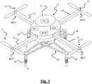
- Figure 1 shows, schematically, an unmanned aerial vehicle 10.
- Figure 1 shows a vertical take-off unmanned aerial vehicle 10 provided with four rotors 11 connected to a central body 12 through four respective beams 13.
- Such a four rotors unmanned aerial vehicle is also referred to as "quadcopter".
- an unmanned aerial vehicle provided with a plurality of rotors is termed "multirotor”.
- the unmanned aerial vehicle 10 could have any number of rotors, four rotors, less than four rotors (for example one or three rotors) or more than four rotors (for example, six or eight rotors).
- the unmanned aerial vehicle comprises a fixed landing gear comprising a structure 15 having horizontal arms (or a star-shaped single-arm) and a plurality of projections 16, in the form of supporting feet 16 facing downwards.
- the number of feet 16 is four, each of them being connected to the respective ends of a four-pointed star shaped plate.
- a four feet gear is particularly advantageous but, according to the invention, a lower number of feet or a greater number of feet could be provided.
- the unmanned aerial vehicle 10 comprises motors MOT for rotating the rotor blades. Preferably, it comprises a motor MOT for each of the rotors 11.
- a camera CAM to take discrete pictures or videos during the flight and/or a sensor SEN can also be provided.
- a memory MEM can also be provided in order to store the data acquired during the flight and/or related to a subsequent mission. All of these components will not be further illustrated or described because they are per se known.
- the supporting feet 16 are preferably identical to one another.
- Each foot 16 has substantially a cylinder shape with a vertical axis with a lower free end 16' and an upper end connected to the structure 15, possibly in the form of a star-shaped plate 15.
- At least one of the supporting feet 16 ( Figure 3a ) comprises a positive electrical contact 16+ and a negative electrical contact 16-connected with a corresponding positive pole and a corresponding negative pole of the battery(s) BAT on board the unmanned aerial vehicle 10.
- each support foot 16 has electrical contacts 16+ and 16- connected to the poles of the battery BAT.
- each supporting foot 16 may have at least one of electrical contacts 16+ and 16-. For instance, when there are four feet, two of them may have respectively a positive and a negative electrical contact. Alternatively, two feet may have only a positive electrical contact and the other two only a negative electrical contact.
- the two electrical contacts 16+ and 16-(or a single electrical contact) are provided only on a part of the supporting feet 16.
- the positive electrical contact 16+ and the negative electrical contact 16- are provided on respective portions of the outer surface of the cylindrical foot 16 and are separated by insulators.
- they could be in the form of metal rings or the like.
- the electrical contacts 16+, 16- are provided in other positions, for example on the lower surface of the free end 16' of at least one foot (see Figures 3b and 4b ).
- one of the two electrical contacts (16+ in Figure 4b ) could be provided at a central circle and the other one (contact 16- in Figure 4b ) at an outer circular crown.
- an arrangement for serial data transfer is provided.
- such an arrangement is accessible from the lower surface of at least one of the feet 16 so that it can cooperate with a corresponding arrangement of (or connected to) the landing platform at the time of the aircraft landing.
- the contact for the serial data transfer is preferably connected to data memory MEM of any known type located on board the unmanned aerial vehicle 10.
- Figures 3c and 4c show a second illustrative example of an alternative electric contact arrangement combined with a serial data transfer arrangement that is not falling under the scope of the invention.
- the lower surface of each foot is substantially divided into four circular sectors: for example two diametrically opposed sectors can be for electrical contacts (16+ and 16-) and the other two diametrically opposed sectors for serial data transfer (one sector for receiving data (Rx) and the other for transmitting data (Tx)).
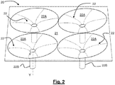
- the landing platform 20 does comprise a substantially flat surface 21 and a plurality of centering housings 22 recessed with respect to the flat surface .
- the housings 22 are suitably arranged and shaped so that the unmanned aerial vehicle 10, once landed, slides and moves to a predetermined parking position.
- the number of housings 22 and their arrangement preferably corresponds to the number and the arrangement of the support feet 16 of the unmanned aerial vehicle 10. Therefore, if the support feet 16 are four and the axes X-X of the feet are located at the four vertexes of a square, likewise the axes Y-Y of the centering housings are arranged in correspondence of the four vertexes of a square with side length equal to that of the side of the square of the feet.
- each centering housing 22 comprises a substantially frusto-conical mouth 22A and a tubular portion 22B which extends downward from the bottom of the frusto-conical mouth 22A.
- the shape of centering housing 22 is a funnel shape.
- the housings 22 are substantially tangent two by two. This reduces the amount of flat surface 21 between a centering housing 22 and the other and reduces the risk that, while landing, one of the feet 16 rests on the flat surface 21 and is not guided towards the center of the centering housings 22.
- the axis Y-Y of the funnel-shaped housings 22 is coaxial with the axis X-X of the projections 16.
- Figure 3a shows schematically a portion of a supporting foot 16 at the bottom of a funnel-shaped housing 22.
- the foot is shown in engagement with two arms 30+, 30-, connected to the ends of a power supply 31 of electric energy.
- the two arms 30+, 30- are staggered to avoid contact between the two poles.
- Figure 3a also schematically shows a presence contact 26, at the lower end 16' of a foot 16. This contact can be for reporting that the foot has reached its bottom position.
- Figures 4a.1 and 4a.2 schematically show the arms in open and closed configuration, respectively.
- the arms 30+, 30- embrace and retain the foot 16, and then the unmanned aerial vehicle 10, to the landing platform 20. Once the arms are opened, the unmanned aerial vehicle 10 is free to take off for a new mission.
- the substantially funnel-shaped housings 22 ensure the unmanned aerial vehicle 10 to slide from an inaccurate landing position to an optimal and perfectly centered landing and parking position.
- each foot 16 is loose in the cylindrical part 22B of the housings 22 .
- At least one of the feet may then be held by the arms closed during recharging of the batteries or can still be retained for safety reasons. Preferably, all of the feet may be retained.
- the unmanned aerial vehicle 10 is retained to the platform 20 through the tightened arms; this is a very advantageous feature, for example when the landing platform is rigidly connected on the roof of a vehicle and the unmanned aerial vehicle is transported therewith: the unmanned aerial vehicle 10 is not likely to separate from the platform 20, which is firmly fixed, and is ready to take off as soon as the charging arms are opened.
- the mass of the unmanned aerial vehicle 10 makes sure that the lower end 16' of the feet is in contact with suitable supporting surfaces 27.
- a contact 26 may be provided at the support surface, as shown in Figure 3a .
- the closure of the arms 30+, 30- can be activated by a presence contact (such as contact 26 of Figure 3a ) or by any other sensor that detects the presence of a foot in a suitable position.
- a presence contact such as contact 26 of Figure 3a
- any other sensor that detects the presence of a foot in a suitable position.
- the combination between the cylindrical feet 16 and the shape of the housings 22 also facilitates the take-off and makes sure that it occurs along the (or in proximity of) vertical direction.
- the tubular portions 22B of the housings 22 guide the feet 16 in the first part of the take-off phase.
- the deviation with respect to the direction of vertical takeoff is however limited by the recessed shape of the housings 22.
- the landing platform 20 also comprises an approaching and pointing system, (for example based on marker tracking).
- This system allows the unmanned aerial vehicle to be positioned substantially vertically relative to the platform and, even automatically, to land ensuring a very precise descent of the unmanned aerial vehicle, for example, with errors of a few centimeters only.
- the marker tracking could be based on an optical and/or radio and/or infrared system.
- G is the weight on the single foot (corresponding to the overall weight of the unmanned aerial vehicle, divided by the number of feet, four in the illustrated embodiment)
- F is the force which tends to make it move toward the inlet (a component of the weight parallel to the sliding plane) and N is the pressing force (a component of the weight perpendicular to the sliding plane)
- G G * sin ⁇ > ⁇ f * G * cos ⁇ and then sin ⁇ > f cos ⁇ f ⁇ tg ⁇
- ⁇ is the inclination angle of the sliding plane with respect to a horizontal position
- f is the friction coefficient between the material of the surface of the housing and the end surface of the feet.
- the inclination of the mouth 22A may have different shapes depending on the materials and/or the available space.
- the mouth 22A is in the form of a substantially truncated cone, with minimum inclination defined above.
- the shape could be represented by a function of the natural logarithm represented in Figure 6 , which guarantees an inclination such as to allow an "accompanied" sliding of the feet to the inlet created by the curve itself.
- a landing platform 20 for an unmanned aerial vehicle 10 is therefore provided which allows the unmanned aerial vehicle to land on an equipped workstation, which ensures an efficient electrical connectivity between the recharging system on board the unmanned aerial vehicle and a battery charger (or power supply) of the recharge platform.
- the present invention ensures recharge times which are comparable to those obtained with the classical charge systems used to date for the battery packs.
- the required accuracy is not such as to require the connectors positioned on the platform to be centered.
- the shape of the housings ensures the unmanned aerial vehicle to slide towards the parking position and optimum charge without the need for further active translation systems of the unmanned aerial vehicle towards the optimal position, or any human intervention.
- the number of funnel-shaped housings (and thus the number of supporting feet) is greater than one.
- it can be three or four. In addition to other advantages reported in the present description, this allows to keep the central part of the unmanned aerial vehicle free for example, for a camera and/or a sensor.
- one or more feet can (also) be used for the networking component, allowing the download of the data collected by the unmanned aerial vehicle during a mission and/or the storing of data in a memory on board the unmanned aerial vehicle. This avoids having complex and heavy equipment on board to transfer the data collected (or used) during a flight.
- the present invention is applicable to any VTOL unmanned aerial vehicle.
Claims (13)
- Landeplattform (20) für ein unbemanntes Luftfahrzeug (10), die eine Vielzahl von im Wesentlichen trichterförmigen Zentriergehäusen (22) umfasst, die dafür konfiguriert sind, mit einer entsprechenden Vielzahl von Vorsprüngen (16) des unbemannten Luftfahrzeugs (10) zum Erreichen einer vorbestimmten Landeposition zusammenzuwirken, wobei die Landeplattform ferner einen positiven elektrischen Kontakt (30+) und einen negativen elektrischen Kontakt (30-) umfasst, die so konfiguriert sind, dass sie mit einem entsprechenden positiven elektrischen Kontakt (16+) und mit einem entsprechenden negativen elektrischen Kontakt (16-) in wenigstens einem der Vorsprünge (16) des unbemannten Luftfahrzeugs (10) zum Wiederauflagen einer Batterie (BAT) des Luftfahrzeugs zusammenwirken,
dadurch gekennzeichnet, dass die elektrischen Kontakte (30+, 30-) der Plattform Arme (30+, 30-) umfassen, die so konfiguriert sind, dass sie sich in einer offenen Position und in einer geschlossenen Position, um einen Vorsprung (16) des unbemannten Luftfahrzeugs (10) zu umklammern, befinden. - Landeplattform (20) nach Anspruch 1, wobei eine Achse (Y-Y) der trichterförmigen Zentriergehäuse (22) koaxial mit einer Achse (X-X) der Vorsprünge (16) ist.
- Landeplattform (20) nach Anspruch 1 oder 2, wobei die im Wesentlichen trichterförmigen Zentriergehäuse (22) eine im Wesentlichen kegelstumpfförmige Mündung (22A) und einen röhrenförmigen Abschnitt (22B), der sich von dem Unterteil der kegelstumpfförmigen Mündung (22A) nach unten erstreckt, umfassen.
- Landeplattform (20) nach einem der vorhergehenden Ansprüche, die ferner eine im Wesentlichen flache Oberfläche (21) umfasst, wobei die im Wesentlichen trichterförmigen Zentriergehäuse (22) in Bezug auf die im Wesentlichen flache Oberfläche (21) eingezogen sind.
- Landeplattform (20) nach Anspruch 4, wobei wenigstens zwei der im Wesentlichen trichterförmigen Zentriergehäuse einander in der Nähe der im Wesentlichen flachen Oberfläche (21) im Wesentlichen berühren.
- Landeplattform (20) nach Anspruch 1, wobei die Arme (30+, 30-) gestaffelt sind, so dass jeder Arm mit dem Vorsprung (16) bei einer unterschiedlichen Höhe des Vorsprungs (16) zusammenwirkt.
- Landeplattform (20) nach Anspruch 1 oder 6, wobei das Schließen der Arme zu dem Vorsprung (16) hin durch einen Drucksensor (26) gesteuert wird.
- Landeplattform (20) nach einem der vorhergehenden Ansprüche, die ferner eine Anordnung zur seriellen Datenübertragung umfasst.
- Landeplattform (20) nach einem der vorhergehenden Ansprüche, wobei die Oberfläche der im Wesentlichen trichterförmigen Zentriergehäuse (22) wenigstens teilweise aus einem Material besteht, das verringerte Reibung mit den Vorsprüngen (16) bietet.
- Landeplattform (20) nach einem der vorhergehenden Ansprüche, wobei wenigstens ein Abschnitt einer Oberfläche der im Wesentlichen trichterförmigen Zentriergehäuse (22) im Wesentlichen einer logarithmischen Kurve folgt.
- Baugruppe, die ein unbemanntes Luftfahrzeug (10) und eine Landeplattform (20) nach einem der vorhergehenden Ansprüche umfasst.
- Baugruppe nach Anspruch 11, wobei das unbemannte Luftfahrzeug (10) ein vertikal startendes unbemanntes Luftfahrzeug ist, das eine Vielzahl von Rotoren und eine Vielzahl von Vorsprüngen (16), die jeweils die Form eines zylindrischen Fußes aufweisen, der sich von einer festen Struktur des unbemannten Luftfahrzeugs nach unten erstreckt, umfasst.
- Baugruppe nach Anspruch 11 oder 12, wobei das unbemannte Luftfahrzeug (10) ebenfalls eine Stecker-/Buchse-Anordnung, um Daten zwischen dem unbemannten Luftfahrzeug (10) und der Landeplattform (20) zu übertragen, umfasst.
Applications Claiming Priority (1)
| Application Number | Priority Date | Filing Date | Title |
|---|---|---|---|
| PCT/EP2014/066790 WO2016019978A1 (en) | 2014-08-05 | 2014-08-05 | Landing platform for an unmanned aerial vehicle |
Publications (2)
| Publication Number | Publication Date |
|---|---|
| EP3177528A1 EP3177528A1 (de) | 2017-06-14 |
| EP3177528B1 true EP3177528B1 (de) | 2019-04-24 |
Family
ID=51300733
Family Applications (1)
| Application Number | Title | Priority Date | Filing Date |
|---|---|---|---|
| EP14749781.2A Active EP3177528B1 (de) | 2014-08-05 | 2014-08-05 | Landeplattform für ein unbemanntes luftfahrzeug |
Country Status (4)
| Country | Link |
|---|---|
| US (1) | US10434885B2 (de) |
| EP (1) | EP3177528B1 (de) |
| CN (1) | CN106715265B (de) |
| WO (1) | WO2016019978A1 (de) |
Families Citing this family (67)
| Publication number | Priority date | Publication date | Assignee | Title |
|---|---|---|---|---|
| USD853939S1 (en) * | 2014-07-25 | 2019-07-16 | University Of Kansas | Aerial vehicle |
| US10407182B1 (en) * | 2015-04-07 | 2019-09-10 | Board Of Trustees Of The University Of Alabama, For And On Behalf Of The University Of Alabama In Huntsville | Unmanned aerial vehicle docking system |
| CZ309628B6 (cs) * | 2015-06-15 | 2023-05-31 | České vysoké učení technické v Praze | Systém zahrnující startovací a přistávací plošinu a členy bezpilotního létajícího prostředku pro kontakt s touto startovací a přistávací plošinou |
| EP3334651B1 (de) | 2015-08-12 | 2024-05-15 | Laitram, L.L.C. | Materialhandhabungslösungen für drohnen |
| US10633115B2 (en) * | 2015-08-17 | 2020-04-28 | Skyyfish, LLC | Autonomous system for unmanned aerial vehicle landing, charging and takeoff |
| BR112018004732B1 (pt) * | 2015-09-11 | 2023-03-07 | Reese Alexander Mozer | Estação de docagem |
| DE102015116118B4 (de) * | 2015-09-23 | 2021-06-02 | Intel Deutschland Gmbh | Bodenstationsvorrichtung für eine Mehrzahl an unbemannten Fluggeräten |
| WO2017083406A1 (en) * | 2015-11-10 | 2017-05-18 | Matternet, Inc. | Methods and systems for transportation using unmanned aerial vehicles |
| FR3043917A1 (fr) * | 2015-11-19 | 2017-05-26 | Chouette | Drone a stockage electrique reparti |
| JP6691794B2 (ja) | 2016-02-26 | 2020-05-13 | 三菱重工業株式会社 | 飛行体の離着陸支援装置及び飛行装置 |
| US20170282734A1 (en) * | 2016-04-04 | 2017-10-05 | Skycatch, Inc. | Unmanned aerial vehicle self-aligning battery assembly |
| US9840327B1 (en) * | 2016-04-29 | 2017-12-12 | Rfrank Llc | Vertical takeoff and landing (VTOL) aircraft and system |
| IL246358A0 (en) * | 2016-06-20 | 2016-11-30 | Fox Yuval | A system for positioning and locking and a method for driverless vehicles |
| WO2018011880A1 (ja) * | 2016-07-12 | 2018-01-18 | 中国電力株式会社 | 無人飛行体、受電コイルユニット、及び充電システム |
| JP6179687B1 (ja) * | 2016-07-12 | 2017-08-16 | 中国電力株式会社 | 無人飛行体、受電コイルユニット、及び充電システム |
| USD814350S1 (en) * | 2016-07-14 | 2018-04-03 | Eyedea Inc. | Drone |
| WO2018034033A1 (ja) | 2016-08-16 | 2018-02-22 | 本郷飛行機株式会社 | 通信制御装置 |
| USD814971S1 (en) * | 2016-10-05 | 2018-04-10 | Geosat Aerospace & Technology Inc. | Micro aerial vehicle |
| US10934019B2 (en) * | 2016-11-29 | 2021-03-02 | Easy Aerial Inc. | Unmanned aerial vehicle charging station with centering mechanism |
| ES2673051A1 (es) * | 2016-12-19 | 2018-06-19 | Universidade De Vigo | Sistema y método de acoplamiento por pares macho-hembra para la recarga eléctrica de aeronaves |
| TWI672887B (zh) * | 2016-12-27 | 2019-09-21 | 財團法人工業技術研究院 | 充電站與充電站模組 |
| CN108237934B (zh) * | 2016-12-27 | 2021-02-26 | 财团法人工业技术研究院 | 充电站与充电站模块 |
| US10537818B2 (en) * | 2017-02-08 | 2020-01-21 | James Vincent Green | Remote control aircraft race launch platform |
| USD853312S1 (en) * | 2017-05-25 | 2019-07-09 | Shenzhen Highgreat Innovation Technology Development Co., Ltd. | Landing gear for unmanned aerial vehicle |
| US11086337B2 (en) * | 2017-06-20 | 2021-08-10 | Planck Aerosystems Inc. | Systems and methods for charging unmanned aerial vehicles on a moving platform |
| US10882410B2 (en) * | 2017-07-19 | 2021-01-05 | Wing Aviation Llc | Systems for charging aerial vehicles |
| TWI628113B (zh) | 2017-08-29 | 2018-07-01 | 財團法人工業技術研究院 | 無人飛行器、判斷無人飛行器降落狀況的系統與方法 |
| RU2674550C1 (ru) * | 2017-10-04 | 2018-12-11 | Общество с ограниченной ответственностью "Инжиниринговая компания "Велес" | Автоматический комплекс дистанционной диагностики электросетевого оборудования |
| FR3072651B1 (fr) * | 2017-10-25 | 2020-06-26 | Airbus Helicopters | Drone et station de recharge adaptes pour une recharge electrique automatique et autonome du drone |
| WO2019114884A1 (de) * | 2017-12-15 | 2019-06-20 | ThyssenKrupp Carbon Components GmbH | Modulares fluggerät |
| US10953984B2 (en) | 2017-12-20 | 2021-03-23 | Wing Aviation Llc | Methods and systems for using an unmanned aerial vehicle (UAV) dedicated to deployment of operational infrastructure |
| US10894601B2 (en) | 2017-12-20 | 2021-01-19 | Wing Aviation Llc | Methods and systems for self-deployment of operational infrastructure by an unmanned aerial vehicle (UAV) |
| WO2019200088A1 (en) * | 2018-04-12 | 2019-10-17 | Laitram, L.L.C. | Autonomous package storage and retrieval system using a drone |
| CN108791930A (zh) * | 2018-05-25 | 2018-11-13 | 芜湖万户航空航天科技有限公司 | 安全无人机起降平台 |
| CN108674683A (zh) * | 2018-05-25 | 2018-10-19 | 芜湖万户航空航天科技有限公司 | 无人飞行器起降调节平台 |
| CN108466701A (zh) * | 2018-05-25 | 2018-08-31 | 芜湖万户航空航天科技有限公司 | 无人机起降调节平台 |
| CN108791931B (zh) * | 2018-05-25 | 2020-04-21 | 芜湖万户航空航天科技有限公司 | 新型无人机起降平台 |
| CN108797399A (zh) * | 2018-05-25 | 2018-11-13 | 芜湖万户航空航天科技有限公司 | 夜用无人机起降调节平台 |
| FR3081840B1 (fr) * | 2018-05-29 | 2020-05-08 | Safran Helicopter Engines | Systeme de ravitaillement pour un vehicule |
| CN108482697B (zh) * | 2018-06-06 | 2023-09-19 | 深圳草莓创新技术有限公司 | 一种无人机自动定位充电装置及其方法 |
| US11453498B2 (en) * | 2018-07-27 | 2022-09-27 | The Boeing Company | Payload engagement systems and related methods |
| US11174027B2 (en) * | 2018-07-27 | 2021-11-16 | The Boeing Company | Vehicle docking systems, payload transfer systems, and related methods |
| USD904967S1 (en) * | 2018-08-29 | 2020-12-15 | Kaiser Enterprises, Llc | Aircraft |
| US10439550B1 (en) * | 2018-09-18 | 2019-10-08 | Sebastian Goodman | System and method for positioning solar panels with automated drones |
| USD945352S1 (en) * | 2018-10-15 | 2022-03-08 | Connell Naylor | Robotically assisted power line aerial diverter mounting tool |
| USD884553S1 (en) * | 2018-10-25 | 2020-05-19 | WAVE3D Co., Ltd | Drone |
| TWD200590S (zh) * | 2019-02-25 | 2019-11-01 | 邱南昌 | 多軸飛行器用座艙容器 |
| US11572197B1 (en) | 2019-03-15 | 2023-02-07 | Alarm.Com Incorporated | Stations for unmanned aerial vehicles |
| US20220185472A1 (en) * | 2019-03-27 | 2022-06-16 | Sony Group Corporation | Information processing apparatus and method, and program |
| EP3738891A1 (de) | 2019-05-17 | 2020-11-18 | Fuvex Civil, SL | Landeplattform für unbemannte luftfahrzeuge |
| US11776136B1 (en) * | 2019-08-27 | 2023-10-03 | Sunflower Labs Inc. | Mobile security camera with multiple landing locations |
| CN111152678B (zh) * | 2020-03-07 | 2023-08-15 | 山东大地新能源科技有限公司 | 基于水面光伏的无人机充电装置及其充电系统 |
| EP3994060A4 (de) | 2020-04-06 | 2022-11-09 | Workhorse Group Inc. | Flugzeugsysteme und -verfahren |
| CN112091553B (zh) * | 2020-08-06 | 2022-03-25 | 浙江浙能天然气运行有限公司 | 一种无人机电池更换装置及其使用方法 |
| CN111977027B (zh) * | 2020-08-19 | 2021-10-12 | 湖南德羽航天装备科技有限公司 | 一种无人机调试用风信子 |
| US11440679B2 (en) * | 2020-10-27 | 2022-09-13 | Cowden Technologies, Inc. | Drone docking station and docking module |
| US11673690B2 (en) | 2021-01-22 | 2023-06-13 | Easy Aerial Inc. | Modular collapsible and portable drone in a box |
| US11685558B2 (en) | 2021-02-01 | 2023-06-27 | Honeywell International Inc. | Marker based smart landing pad |
| US20220306319A1 (en) * | 2021-03-29 | 2022-09-29 | The Boeing Company | Vertical Air Vehicle Takeoff and Landing Stabilization Apparatuses, Systems, and Methods |
| US20220306284A1 (en) * | 2021-03-29 | 2022-09-29 | The Boeing Company | Vertical Air Vehicle Takeoff and Landing Stabilization Apparatuses, Systems, and Methods |
| US20220306320A1 (en) * | 2021-03-29 | 2022-09-29 | The Boeing Company | Vertical Air Vehicle Takeoff and Landing Stabilization Apparatuses, Systems, and Methods |
| CN112874805B (zh) * | 2021-04-09 | 2022-12-09 | 翼飞智能科技(武汉)有限公司 | 无人机存放舱以及具有无人机存放舱的无人机设备 |
| CN113104216B (zh) * | 2021-04-12 | 2024-02-02 | 山东叮当云数字科技有限公司 | 一种基于智慧灯杆的无人机停机管控系统 |
| US20230060684A1 (en) * | 2021-08-26 | 2023-03-02 | United Parcel Service Of America, Inc. | Locking mechanism and container for delivering items |
| CA3227521A1 (en) * | 2021-08-26 | 2023-02-02 | Julian Bell | Unmanned aerial vehicle (uav) landing systems |
| CN114906339A (zh) * | 2022-05-16 | 2022-08-16 | 山东欧齐珞信息科技有限公司 | 一种无人机用复合漏斗形停机平台 |
| CN117539282A (zh) * | 2022-07-26 | 2024-02-09 | 峰飞航空科技(昆山)有限公司 | 飞行器姿态控制方法、装置、电子设备和存储介质 |
Family Cites Families (11)
| Publication number | Priority date | Publication date | Assignee | Title |
|---|---|---|---|---|
| US20040256519A1 (en) * | 2003-03-12 | 2004-12-23 | Ellis Stephen C. | System for recovery of aerial vehicles |
| US20070228214A1 (en) * | 2005-09-26 | 2007-10-04 | Honeywell International Inc. | Autonomous launch pad for micro air vehicles |
| DE102007003458A1 (de) * | 2007-01-24 | 2008-07-31 | Diehl Bgt Defence Gmbh & Co. Kg | Einrichtung zur Energieversorgung eines batteriebetriebenen Kleinfluggerätes |
| US8205820B2 (en) | 2009-02-03 | 2012-06-26 | Honeywell International Inc. | Transforming unmanned aerial-to-ground vehicle |
| US8453966B2 (en) | 2009-02-12 | 2013-06-04 | Aerovel Corporation | Method and apparatus for automated launch, retrieval, and servicing of a hovering aircraft |
| WO2012064891A2 (en) | 2010-11-09 | 2012-05-18 | Colorado Seminary, Which Owns And Operates The University Of Denver | Intelligent self-leveling docking system |
| US20120271461A1 (en) * | 2011-04-20 | 2012-10-25 | Spata Gregory P | Capturing environmental information |
| CN202929383U (zh) * | 2012-09-11 | 2013-05-08 | 深圳一电科技有限公司 | 无人机及其自动充电系统 |
| CN103645740B (zh) * | 2013-12-30 | 2016-02-17 | 中国科学院自动化研究所 | 基于无线充电奇数轴飞行器的智能巡航机器人 |
| US9561871B2 (en) * | 2014-05-07 | 2017-02-07 | Deere & Company | UAV docking system and method |
| KR101643718B1 (ko) * | 2014-07-16 | 2016-07-28 | 한국항공우주연구원 | 지주형 무인비행체 격납충전장치 및 이를 이용한 무인비행체의 격납 및 충전방법 |
-
2014
- 2014-08-05 CN CN201480081767.XA patent/CN106715265B/zh active Active
- 2014-08-05 US US15/500,291 patent/US10434885B2/en active Active
- 2014-08-05 EP EP14749781.2A patent/EP3177528B1/de active Active
- 2014-08-05 WO PCT/EP2014/066790 patent/WO2016019978A1/en active Application Filing
Also Published As
| Publication number | Publication date |
|---|---|
| US10434885B2 (en) | 2019-10-08 |
| US20170217323A1 (en) | 2017-08-03 |
| WO2016019978A1 (en) | 2016-02-11 |
| CN106715265B (zh) | 2019-08-16 |
| CN106715265A (zh) | 2017-05-24 |
| EP3177528A1 (de) | 2017-06-14 |
Similar Documents
| Publication | Publication Date | Title |
|---|---|---|
| EP3177528B1 (de) | Landeplattform für ein unbemanntes luftfahrzeug | |
| US11608193B2 (en) | UAV retrieval and deployment system | |
| EP3487760B1 (de) | Verfahren und systeme zur verankerung eines unbemannten luftfahrzeugs auf einer bodenstation | |
| US10953999B2 (en) | Unmanned aerial vehicle docking system | |
| US20210276732A1 (en) | Pod cover system for a vertical take-off and landing (vtol) unmanned aerial vehicle (uav) | |
| US9505493B2 (en) | System for automatic takeoff and landing by interception of small UAVs | |
| US11721995B2 (en) | Battery management system | |
| US20190002127A1 (en) | Autonomous docking station for drones | |
| JP6395835B2 (ja) | Uavのバッテリー電源バックアップシステムおよび方法 | |
| US20170297445A1 (en) | Cone Shaped Docking Mechanism Provides Rigid Connection Between 2 UAVs and Serves as Charging Port to Provide Real Time Charging Power in the air as well as Serves as Ground UAV Charging Stations | |
| US20170225802A1 (en) | Systems and methods for deployment and operation of vertical take-off and landing (vtol) unmanned aerial vehicles | |
| WO2015195175A2 (en) | System for automatic takeoff and landing by interception of small uavs | |
| US20150069968A1 (en) | Vehicle replenishment | |
| US20200044463A1 (en) | Unmanned aerial vehicle and unmanned aerial vehicle automatic charging device | |
| JP6791561B2 (ja) | Uavにエネルギーを供給する方法、及び装置 | |
| JP2018100088A (ja) | Uavにエネルギーを供給する方法、及びuav | |
| US9862504B1 (en) | Positioning hovering objects for docking | |
| EP3455129B1 (de) | Systeme und verfahren im zusammenhang mit umwandelbaren unbemannten luftfahrzeugen | |
| RU168376U1 (ru) | Малогабаритный беспилотный летательный аппарат | |
| US20240021091A1 (en) | Method, system and components providing a secure internet connected aerial network for continuous drone operation and surveillance | |
| CN215753078U (zh) | 一种无人机停机坪、无人机停靠系统及无人机系统 |
Legal Events
| Date | Code | Title | Description |
|---|---|---|---|
| STAA | Information on the status of an ep patent application or granted ep patent |
Free format text: STATUS: THE INTERNATIONAL PUBLICATION HAS BEEN MADE |
|
| PUAI | Public reference made under article 153(3) epc to a published international application that has entered the european phase |
Free format text: ORIGINAL CODE: 0009012 |
|
| STAA | Information on the status of an ep patent application or granted ep patent |
Free format text: STATUS: REQUEST FOR EXAMINATION WAS MADE |
|
| 17P | Request for examination filed |
Effective date: 20170221 |
|
| AK | Designated contracting states |
Kind code of ref document: A1 Designated state(s): AL AT BE BG CH CY CZ DE DK EE ES FI FR GB GR HR HU IE IS IT LI LT LU LV MC MK MT NL NO PL PT RO RS SE SI SK SM TR |
|
| AX | Request for extension of the european patent |
Extension state: BA ME |
|
| DAX | Request for extension of the european patent (deleted) | ||
| GRAP | Despatch of communication of intention to grant a patent |
Free format text: ORIGINAL CODE: EPIDOSNIGR1 |
|
| STAA | Information on the status of an ep patent application or granted ep patent |
Free format text: STATUS: GRANT OF PATENT IS INTENDED |
|
| INTG | Intention to grant announced |
Effective date: 20181206 |
|
| RIN1 | Information on inventor provided before grant (corrected) |
Inventor name: FICI, GIAN PIERO Inventor name: GASPARDONE, MARCO Inventor name: ANTONINI, ROBERTO |
|
| GRAS | Grant fee paid |
Free format text: ORIGINAL CODE: EPIDOSNIGR3 |
|
| GRAA | (expected) grant |
Free format text: ORIGINAL CODE: 0009210 |
|
| STAA | Information on the status of an ep patent application or granted ep patent |
Free format text: STATUS: THE PATENT HAS BEEN GRANTED |
|
| AK | Designated contracting states |
Kind code of ref document: B1 Designated state(s): AL AT BE BG CH CY CZ DE DK EE ES FI FR GB GR HR HU IE IS IT LI LT LU LV MC MK MT NL NO PL PT RO RS SE SI SK SM TR |
|
| REG | Reference to a national code |
Ref country code: GB Ref legal event code: FG4D |
|
| REG | Reference to a national code |
Ref country code: CH Ref legal event code: EP |
|
| REG | Reference to a national code |
Ref country code: AT Ref legal event code: REF Ref document number: 1123849 Country of ref document: AT Kind code of ref document: T Effective date: 20190515 Ref country code: IE Ref legal event code: FG4D |
|
| REG | Reference to a national code |
Ref country code: DE Ref legal event code: R096 Ref document number: 602014045357 Country of ref document: DE |
|
| REG | Reference to a national code |
Ref country code: NL Ref legal event code: MP Effective date: 20190424 |
|
| REG | Reference to a national code |
Ref country code: LT Ref legal event code: MG4D |
|
| PG25 | Lapsed in a contracting state [announced via postgrant information from national office to epo] |
Ref country code: NL Free format text: LAPSE BECAUSE OF FAILURE TO SUBMIT A TRANSLATION OF THE DESCRIPTION OR TO PAY THE FEE WITHIN THE PRESCRIBED TIME-LIMIT Effective date: 20190424 |
|
| PG25 | Lapsed in a contracting state [announced via postgrant information from national office to epo] |
Ref country code: SE Free format text: LAPSE BECAUSE OF FAILURE TO SUBMIT A TRANSLATION OF THE DESCRIPTION OR TO PAY THE FEE WITHIN THE PRESCRIBED TIME-LIMIT Effective date: 20190424 Ref country code: HR Free format text: LAPSE BECAUSE OF FAILURE TO SUBMIT A TRANSLATION OF THE DESCRIPTION OR TO PAY THE FEE WITHIN THE PRESCRIBED TIME-LIMIT Effective date: 20190424 Ref country code: PT Free format text: LAPSE BECAUSE OF FAILURE TO SUBMIT A TRANSLATION OF THE DESCRIPTION OR TO PAY THE FEE WITHIN THE PRESCRIBED TIME-LIMIT Effective date: 20190824 Ref country code: ES Free format text: LAPSE BECAUSE OF FAILURE TO SUBMIT A TRANSLATION OF THE DESCRIPTION OR TO PAY THE FEE WITHIN THE PRESCRIBED TIME-LIMIT Effective date: 20190424 Ref country code: LT Free format text: LAPSE BECAUSE OF FAILURE TO SUBMIT A TRANSLATION OF THE DESCRIPTION OR TO PAY THE FEE WITHIN THE PRESCRIBED TIME-LIMIT Effective date: 20190424 Ref country code: NO Free format text: LAPSE BECAUSE OF FAILURE TO SUBMIT A TRANSLATION OF THE DESCRIPTION OR TO PAY THE FEE WITHIN THE PRESCRIBED TIME-LIMIT Effective date: 20190724 Ref country code: AL Free format text: LAPSE BECAUSE OF FAILURE TO SUBMIT A TRANSLATION OF THE DESCRIPTION OR TO PAY THE FEE WITHIN THE PRESCRIBED TIME-LIMIT Effective date: 20190424 Ref country code: FI Free format text: LAPSE BECAUSE OF FAILURE TO SUBMIT A TRANSLATION OF THE DESCRIPTION OR TO PAY THE FEE WITHIN THE PRESCRIBED TIME-LIMIT Effective date: 20190424 |
|
| PG25 | Lapsed in a contracting state [announced via postgrant information from national office to epo] |
Ref country code: GR Free format text: LAPSE BECAUSE OF FAILURE TO SUBMIT A TRANSLATION OF THE DESCRIPTION OR TO PAY THE FEE WITHIN THE PRESCRIBED TIME-LIMIT Effective date: 20190725 Ref country code: PL Free format text: LAPSE BECAUSE OF FAILURE TO SUBMIT A TRANSLATION OF THE DESCRIPTION OR TO PAY THE FEE WITHIN THE PRESCRIBED TIME-LIMIT Effective date: 20190424 Ref country code: RS Free format text: LAPSE BECAUSE OF FAILURE TO SUBMIT A TRANSLATION OF THE DESCRIPTION OR TO PAY THE FEE WITHIN THE PRESCRIBED TIME-LIMIT Effective date: 20190424 Ref country code: BG Free format text: LAPSE BECAUSE OF FAILURE TO SUBMIT A TRANSLATION OF THE DESCRIPTION OR TO PAY THE FEE WITHIN THE PRESCRIBED TIME-LIMIT Effective date: 20190724 Ref country code: LV Free format text: LAPSE BECAUSE OF FAILURE TO SUBMIT A TRANSLATION OF THE DESCRIPTION OR TO PAY THE FEE WITHIN THE PRESCRIBED TIME-LIMIT Effective date: 20190424 |
|
| REG | Reference to a national code |
Ref country code: AT Ref legal event code: MK05 Ref document number: 1123849 Country of ref document: AT Kind code of ref document: T Effective date: 20190424 |
|
| PG25 | Lapsed in a contracting state [announced via postgrant information from national office to epo] |
Ref country code: IS Free format text: LAPSE BECAUSE OF FAILURE TO SUBMIT A TRANSLATION OF THE DESCRIPTION OR TO PAY THE FEE WITHIN THE PRESCRIBED TIME-LIMIT Effective date: 20190824 |
|
| REG | Reference to a national code |
Ref country code: DE Ref legal event code: R097 Ref document number: 602014045357 Country of ref document: DE |
|
| PG25 | Lapsed in a contracting state [announced via postgrant information from national office to epo] |
Ref country code: DK Free format text: LAPSE BECAUSE OF FAILURE TO SUBMIT A TRANSLATION OF THE DESCRIPTION OR TO PAY THE FEE WITHIN THE PRESCRIBED TIME-LIMIT Effective date: 20190424 Ref country code: SK Free format text: LAPSE BECAUSE OF FAILURE TO SUBMIT A TRANSLATION OF THE DESCRIPTION OR TO PAY THE FEE WITHIN THE PRESCRIBED TIME-LIMIT Effective date: 20190424 Ref country code: CZ Free format text: LAPSE BECAUSE OF FAILURE TO SUBMIT A TRANSLATION OF THE DESCRIPTION OR TO PAY THE FEE WITHIN THE PRESCRIBED TIME-LIMIT Effective date: 20190424 Ref country code: RO Free format text: LAPSE BECAUSE OF FAILURE TO SUBMIT A TRANSLATION OF THE DESCRIPTION OR TO PAY THE FEE WITHIN THE PRESCRIBED TIME-LIMIT Effective date: 20190424 Ref country code: EE Free format text: LAPSE BECAUSE OF FAILURE TO SUBMIT A TRANSLATION OF THE DESCRIPTION OR TO PAY THE FEE WITHIN THE PRESCRIBED TIME-LIMIT Effective date: 20190424 Ref country code: AT Free format text: LAPSE BECAUSE OF FAILURE TO SUBMIT A TRANSLATION OF THE DESCRIPTION OR TO PAY THE FEE WITHIN THE PRESCRIBED TIME-LIMIT Effective date: 20190424 |
|
| PG25 | Lapsed in a contracting state [announced via postgrant information from national office to epo] |
Ref country code: SM Free format text: LAPSE BECAUSE OF FAILURE TO SUBMIT A TRANSLATION OF THE DESCRIPTION OR TO PAY THE FEE WITHIN THE PRESCRIBED TIME-LIMIT Effective date: 20190424 |
|
| PLBE | No opposition filed within time limit |
Free format text: ORIGINAL CODE: 0009261 |
|
| STAA | Information on the status of an ep patent application or granted ep patent |
Free format text: STATUS: NO OPPOSITION FILED WITHIN TIME LIMIT |
|
| PG25 | Lapsed in a contracting state [announced via postgrant information from national office to epo] |
Ref country code: TR Free format text: LAPSE BECAUSE OF FAILURE TO SUBMIT A TRANSLATION OF THE DESCRIPTION OR TO PAY THE FEE WITHIN THE PRESCRIBED TIME-LIMIT Effective date: 20190424 |
|
| 26N | No opposition filed |
Effective date: 20200127 |
|
| PG25 | Lapsed in a contracting state [announced via postgrant information from national office to epo] |
Ref country code: LU Free format text: LAPSE BECAUSE OF NON-PAYMENT OF DUE FEES Effective date: 20190805 Ref country code: MC Free format text: LAPSE BECAUSE OF FAILURE TO SUBMIT A TRANSLATION OF THE DESCRIPTION OR TO PAY THE FEE WITHIN THE PRESCRIBED TIME-LIMIT Effective date: 20190424 Ref country code: SI Free format text: LAPSE BECAUSE OF FAILURE TO SUBMIT A TRANSLATION OF THE DESCRIPTION OR TO PAY THE FEE WITHIN THE PRESCRIBED TIME-LIMIT Effective date: 20190424 Ref country code: CH Free format text: LAPSE BECAUSE OF NON-PAYMENT OF DUE FEES Effective date: 20190831 Ref country code: LI Free format text: LAPSE BECAUSE OF NON-PAYMENT OF DUE FEES Effective date: 20190831 |
|
| REG | Reference to a national code |
Ref country code: BE Ref legal event code: MM Effective date: 20190831 |
|
| PG25 | Lapsed in a contracting state [announced via postgrant information from national office to epo] |
Ref country code: IE Free format text: LAPSE BECAUSE OF NON-PAYMENT OF DUE FEES Effective date: 20190805 |
|
| PG25 | Lapsed in a contracting state [announced via postgrant information from national office to epo] |
Ref country code: BE Free format text: LAPSE BECAUSE OF NON-PAYMENT OF DUE FEES Effective date: 20190831 |
|
| PG25 | Lapsed in a contracting state [announced via postgrant information from national office to epo] |
Ref country code: CY Free format text: LAPSE BECAUSE OF FAILURE TO SUBMIT A TRANSLATION OF THE DESCRIPTION OR TO PAY THE FEE WITHIN THE PRESCRIBED TIME-LIMIT Effective date: 20190424 |
|
| PG25 | Lapsed in a contracting state [announced via postgrant information from national office to epo] |
Ref country code: MT Free format text: LAPSE BECAUSE OF FAILURE TO SUBMIT A TRANSLATION OF THE DESCRIPTION OR TO PAY THE FEE WITHIN THE PRESCRIBED TIME-LIMIT Effective date: 20190424 Ref country code: HU Free format text: LAPSE BECAUSE OF FAILURE TO SUBMIT A TRANSLATION OF THE DESCRIPTION OR TO PAY THE FEE WITHIN THE PRESCRIBED TIME-LIMIT; INVALID AB INITIO Effective date: 20140805 |
|
| PG25 | Lapsed in a contracting state [announced via postgrant information from national office to epo] |
Ref country code: MK Free format text: LAPSE BECAUSE OF FAILURE TO SUBMIT A TRANSLATION OF THE DESCRIPTION OR TO PAY THE FEE WITHIN THE PRESCRIBED TIME-LIMIT Effective date: 20190424 |
|
| P01 | Opt-out of the competence of the unified patent court (upc) registered |
Effective date: 20230527 |
|
| P02 | Opt-out of the competence of the unified patent court (upc) changed |
Effective date: 20230530 |
|
| PGFP | Annual fee paid to national office [announced via postgrant information from national office to epo] |
Ref country code: IT Payment date: 20230822 Year of fee payment: 10 Ref country code: GB Payment date: 20230828 Year of fee payment: 10 |
|
| PGFP | Annual fee paid to national office [announced via postgrant information from national office to epo] |
Ref country code: FR Payment date: 20230825 Year of fee payment: 10 Ref country code: DE Payment date: 20230829 Year of fee payment: 10 |