EP3177002A2 - Verbessertes abtastdesign - Google Patents
Verbessertes abtastdesign Download PDFInfo
- Publication number
- EP3177002A2 EP3177002A2 EP17151477.1A EP17151477A EP3177002A2 EP 3177002 A2 EP3177002 A2 EP 3177002A2 EP 17151477 A EP17151477 A EP 17151477A EP 3177002 A2 EP3177002 A2 EP 3177002A2
- Authority
- EP
- European Patent Office
- Prior art keywords
- camera
- scanner
- platen
- document
- scanning
- Prior art date
- Legal status (The legal status is an assumption and is not a legal conclusion. Google has not performed a legal analysis and makes no representation as to the accuracy of the status listed.)
- Withdrawn
Links
Images


Classifications
-
- B—PERFORMING OPERATIONS; TRANSPORTING
- B60—VEHICLES IN GENERAL
- B60R—VEHICLES, VEHICLE FITTINGS, OR VEHICLE PARTS, NOT OTHERWISE PROVIDED FOR
- B60R1/00—Optical viewing arrangements; Real-time viewing arrangements for drivers or passengers using optical image capturing systems, e.g. cameras or video systems specially adapted for use in or on vehicles
- B60R1/02—Rear-view mirror arrangements
- B60R1/08—Rear-view mirror arrangements involving special optical features, e.g. avoiding blind spots, e.g. convex mirrors; Side-by-side associations of rear-view and other mirrors
- B60R1/083—Anti-glare mirrors, e.g. "day-night" mirrors
- B60R1/084—Anti-glare mirrors, e.g. "day-night" mirrors using a removable filtering or hiding screen
-
- H—ELECTRICITY
- H04—ELECTRIC COMMUNICATION TECHNIQUE
- H04N—PICTORIAL COMMUNICATION, e.g. TELEVISION
- H04N1/00—Scanning, transmission or reproduction of documents or the like, e.g. facsimile transmission; Details thereof
- H04N1/04—Scanning arrangements, i.e. arrangements for the displacement of active reading or reproducing elements relative to the original or reproducing medium, or vice versa
- H04N1/19—Scanning arrangements, i.e. arrangements for the displacement of active reading or reproducing elements relative to the original or reproducing medium, or vice versa using multi-element arrays
- H04N1/195—Scanning arrangements, i.e. arrangements for the displacement of active reading or reproducing elements relative to the original or reproducing medium, or vice versa using multi-element arrays the array comprising a two-dimensional array or a combination of two-dimensional arrays
-
- A—HUMAN NECESSITIES
- A63—SPORTS; GAMES; AMUSEMENTS
- A63F—CARD, BOARD, OR ROULETTE GAMES; INDOOR GAMES USING SMALL MOVING PLAYING BODIES; VIDEO GAMES; GAMES NOT OTHERWISE PROVIDED FOR
- A63F9/00—Games not otherwise provided for
- A63F9/24—Electric games; Games using electronic circuits not otherwise provided for
- A63F2009/2401—Detail of input, input devices
- A63F2009/2411—Input form cards, tapes, discs
- A63F2009/2419—Optical
- A63F2009/2425—Scanners, e.g. for scanning regular characters
-
- A—HUMAN NECESSITIES
- A63—SPORTS; GAMES; AMUSEMENTS
- A63F—CARD, BOARD, OR ROULETTE GAMES; INDOOR GAMES USING SMALL MOVING PLAYING BODIES; VIDEO GAMES; GAMES NOT OTHERWISE PROVIDED FOR
- A63F3/00—Board games; Raffle games
- A63F3/06—Lottos or bingo games; Systems, apparatus or devices for checking such games
- A63F3/0625—Devices for filling-in or checking
- A63F3/064—Electric devices for filling-in or checking
Definitions
- An Embedded Optical Signature can be added to a lottery scratch-off ticket as, for example, an image under the scratch-off coating.
- the EOS validation data revealed from under the removed scratch-off coating can then be processed with the ticket's barcode data (not hidden under a scratch-off coating) allowing the ticket to be validated without any other action required from the person initiating the transaction.
- An EOS can also be used to ensure the authenticity of a printed document, such as an on-line lottery ticket, provide copyright protection, or carry additional information such as the name and address of an individual filling out a form.
- a scanner or camera is generally necessary to capture a digital image of the document.
- An inexpensive camera, linear sensor, or contact image sensor may be used to provide this image capture functionality.
- certain problems may be encountered in such applications. For example, whether attempting to capture an EOS or other information on a printed document, a scanner should preferably be able to capture the relevant data without interference from the surrounding environment.
- Linear or Contact Image Sensors typically include a mechanical mechanism that either moves the document past the sensor or vice versa.
- One method of isolating the scan head from environmental light contamination is to provide intrinsic illumination in a darkened environment.
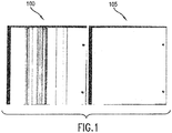
- Fig. 1 illustrates this problem with scan 100 being of a blank document with small particles of dirt on the scan head and scan 105 showing the same document with a clean scan head.
- This susceptibility to dirt-induced noise makes this type of scanner disfavored for dirty environments such as, for example, the processing of scratch-off lottery tickets.
- a questionnaire or bet slip is completed with a ballpoint pen and a sufficient amount of time is not allowed for the ink to completely dry, ink can transfer to the scan head and create this type of dirt-induced noise in linear/CIS scanners.
- the reliability of a mechanical scanning mechanism is inherently worse than a fully electronic device.
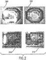
- Two-dimensional camera scanners can minimize the effects of dirt and ink noise while increasing reliability by eliminating the need to physically move the document or scan head. Additionally, mounting the camera some distance away from the target document creates an open space that isolates the camera lens from the dirt/ink noise sources. If the camera is placed above a platen, the dirt and ink noise problem can be further reduced because a fresh document is presented for each scan with no visible residual dirt left on a scanning surface or glass platen if the document is scanned face up. Unfortunately, the spacing of the camera above a platen allows direct-reflection-noise (i.e., glare) to be introduced from ambient light or poorly positioned scanner lighting sources. Referring to Fig.
- image 200 shows a scratch-off lottery ticket with ambient glare while image 205 shows a scratch-off lottery ticket without ambient glare.
- Image 210 shows a camera image of a scratch-off lottery ticket with glare from internal lighting while image 215 shows the same lottery ticket without glare from internal lighting.
- Glare noise from ambient light sources can be eliminated by encasing the camera scanner mechanism in a light tight enclosure. However, opening a door or moving a curtain may be cumbersome and slow for an operator. Careful placement of light sources can also eliminate scanner-internal glare noise. As illustrated in Fig. 3A , glare is eliminated or reduced as light sources 300 are moved into non-reflection areas 305.
- Fig. 3B shows a camera view of a platen 320 with a light source about 2 inches above on both sides while platen 325 has a light source and diffuser about 2 inches above on both sides such that less glare is apparent on the platen.
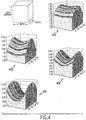
- Fig. 4 illustrates the light intensity relative to the x-y location on a platen with various locations for the light sources.
- graph 400 represents a platen with side illumination sources 1 inch above the platen
- graph 405 represents a platen with side illumination sources 2 inches above the platen
- graph 410 represents a platen with side illumination sources 4 inches above the platen
- graph 415 represents a platen with side illumination sources 5 inches above the platen
- moving the light sources further away from the platen greatly improves the side to side illumination uniformity and substantially improves front to rear illumination uniformity, but requires significantly more space for the scanner housing.
- mounting a camera above a platen and not securing the document to a flat plane introduces a potential new error source if the document is bowed. More specifically, variability in the distance between the scanned surface and the camera can introduce a locational error that limits the size of symbols.
- Trapezoidal error is introduced if the camera is not mounted perfectly parallel to the plane of the platen. If a mirror is added in an attempt to reduce the size of the scanner housing, proper alignment becomes even more critical because any alignment error will be magnified by a factor of two.
- a camera and platen based scanning system is susceptible to errors caused by the human operator improperly aligning the document on the platen. This problem is less of an issue with motorized one-dimensional scanners (e.g., CIS) since the motor can be used to help align the document.
- motorized one-dimensional scanners e.g., CIS
- the method for operating a scanning device comprises the steps:
- the optical element comprises a raster scan camera.
- the scanner lights comprise light-emitting diodes.
- the present invention includes a scanner having a shield surrounding the scanner lens to block ambient or interfering light sources.
- the present invention includes an enclosure for a scanner that defines an opening to an interior space where the platen is located.
- the enclosure provides for shielding the platen along at least three sides so as to minimize or eliminate glare or interference from external light sources.
- the present invention also includes an exemplary embodiment in which the scanner platen is tilted at a slight downward angle from the opening to the enclosure.
- the side of the enclosure or a stop-element within the enclosure assists with settling the document into place after insertion.
- the tilted platen helps to ensure that the document being scanned is properly positioned and/or oriented.
- Another exemplary embodiment of the present invention includes a gimbaled mount for the camera scanner.
- the gimbaled mount allows for the camera to be properly aligned relative to the platen so as to minimize trapezoidal error.
- a locking mechanism may be provided to secure the position of the camera once aligned.
- the scanner enclosure is constructed within precise tolerances to ensure proper alignment and reduce or eliminate trapezoidal error.
- a scanner design in which the light source is located below a mirror to reduce the housing height.
- the mirror is located near the target document so that the horizontal distance between light sources decreases to approximately the target width plus an offset.
- the present invention also includes an embodiment in which a scanner's light sources are synchronized with the camera's raster scanning. Multiple light sources are positioned relative to the platen at specific locations such that as the camera scans the documents, the lights are turned on and off in a sequence that illuminates the document while eliminating or minimizing glare or direct reflection.
- the present invention also includes an improved scanner embodiment in which the brightness of the scanner's internal lighting is increased so as to reduce the scanner's sensitivity to ambient or other external light sources.
- an improved scanner design includes a monochromatic or near monochromatic light source coupled with a narrow band filter to minimize or eliminate interfering light.
- the present invention also includes an exemplary embodiment in which different color light sources (e.g., red, green, blue) are built into the scanner.
- different color light sources e.g., red, green, blue
- the camera can be programmed to first capture one frame with the scanner's lights extinguished. Therefore, any light readings that are recorded in this frame represent the ambient environmental light noise.
- the average magnitude of the intensities of all of the camera's red, blue, and green pixels are compared and the color with the lowest average reading is selected for illumination and processing, since it represents the lowest light level of the environmental noise.
- an improved scanner has multiple cameras with overlapping or nearly overlapping fields of view of the same platen. During processing, the overlapping area from the resulting images is either eliminated or combined to achieve a composite image. In still another embodiment of the present invention, multiple cameras are each arranged to view all or most of the entire platen. The resulting image is then evaluated (e.g. using software) to eliminate or reduce one or more of the scanner errors previously described above.
- a preferred scanning device comprises:
- said scanning device further comprises at least one scanner light positioned within the interior of the enclosure in a manner that minimizes direct-reflections to the optical element.
- said scanning device further comprises:
- said scanning device further comprises:
- said scanning device further comprises locking elements for fixing the position for said gimbaled mount about the multiple pivot points.
- said enclosure defines an input slot for receipt of a ticket
- the scanning device further comprises:
- a preferred scanning device comprises:
- said plurality of light sources comprises light-emitting diodes.
- a preferred scanning device comprises:
- said substantially monochromatic light source comprises light-emitting diodes.
- filter comprises a 500 nanometer bandpass filter.
- a preferred method for operating a scanning device comprises the steps:
- said scanner lights comprise light-emitting diodes.
- a preferred scanning device comprises:
- a preferred scanning device comprises:
- a preferred method for operating a scanning device comprises the steps:
- a preferred method for operating a scanning device comprises the steps:
- said comparing step comprises Transverse Mercator projection.
- a preferred scanning device comprises:
- said scanning device further comprises a platen that is tilted within the interior of said enclosure and positioned relative to the opening of said enclosure so as to provide for positioning of documents therein.
- said platen is positioned relative to the opening of said enclosure so as to minimize direct reflections from ambient light sources.
- said scanning device further comprises:
- said scanning device further comprises locking elements for fixing the position of each said gimbaled mount about the multiple pivot points.
- said enclosure defines an input slot for receipt of a ticket and the scanning device further comprises:
- the present invention includes apparatus and methods for using two-dimensional camera based scanning systems to capture information on documents while minimizing error sources previously described. Different embodiments and methods are discussed that can be used in combination or separately as desired. Additionally, a method of aligning on-line tickets that permits branding (visibly altering the ticket to indicate that its status has changed - e.g., paid or cancelled) is also disclosed.
- One exemplary technique for protecting a camera-based scanner from environmentally induced noise is to partially enclose the scan area and physically alter the platen.
- camera and lens 500 are protected by a shield 505 from ambient light 510 that could cause lens flaring - i.e. bright spots caused by a light source shining directly into the lens.
- a shield 505 from ambient light 510 that could cause lens flaring - i.e. bright spots caused by a light source shining directly into the lens.
- low angle light sources can induce lens flaring or glare in some locations.
- the noise source can be misdiagnosed as an intermittent scanner problem.
- the light shield 505 should preferably encircle the camera lens 360 degrees and have a non-glossy/non-reflective finish to avoid glare from ambient light sources 510 wherever a document is not covering the platen.
- FIG. 6 includes multiple embodiments of cabinets or enclosures 600, 605, 610, and 615 that each have an opening 620 for operator access.
- Each enclosure includes a scanner (e.g. a camera-based scanner) but may also include other components such as a display monitor or transaction register.
- a scanner e.g. a camera-based scanner
- the only side of the camera-based scanner that is exposed to potential ambient light noise is the same side that the human operator would normally be blocking with his or her body, virtually eliminating glare noise from ambient environmental sources.
- Such three-sided enclosures 600, 605, 610, and 615 also allow for multiple scanner lights that can be placed to provide uniform illumination while at the same time avoiding any direct reflections to the camera.
- the three-sided enclosure's interior should also be a non-glossy / non-reflective finish.
- the three-sided enclosures 600, 605, 610, and 615 create a semi-dark scanning area that enables the camera-based scanner to use various optical techniques to authenticate a document - e.g., illuminate and detect ultraviolet or infrared fluorescence from a taggant present on authentic documents. It should be noted that this type of document authentication would be virtually impossible with a housing design that allows excessive ambient light into the scanning area.
- a tilted platen that is tilted at a slight angle (e.g., 10 degrees) down from the document input opening.
- a tilted platen could be provided within opening 620 of enclosures 600, 605, 610, and 615.
- Such tilted platen will cause the document to slide and settle against a wall or other element of the scanner such that the document is correctly positioned in the camera's field of view (provided the camera must also be physically arranged to be parallel to the tilted platen).
- many document insertion errors can be automatically corrected.
- tilting the platen below the opening will also help reduce glare from ambient environmental light sources.
- trapezoidal error can also be introduced if the camera is not mounted parallel to the plane of the platen. For example, assuming an 8.1-inch (206 mm) focal length and 4-inch (102 mm) field of view, trapezoidal error increases by approximately 1.2% on the farthest edge of the platen for every degree that the platen is offset relative to the camera. If a mirror is added, even more chances for an alignment problem are created because the alignment error increases by a factor of two over a camera direct-view design. For example, with a mirror added at a nominal 45° angle between the camera view and the platen, a one degree sum total tilt error (i.e., platen, mirror, and camera combined) causes 2.4% distortion at the far end of the platen. Two degrees of tilt results in 4.8% distortion and so on.
- a one degree sum total tilt error i.e., platen, mirror, and camera combined
- FIGs. 7A and 7B provide an exemplary embodiment of a gimbaled camera mount 700.
- the mount includes a surface 710 upon which the camera may be mounted. Pivot points 715, 720, 725, and 730 allow the orientation of the camera to be aligned as desired.
- locking screws (not shown) can be used to ensure that the assembly does not move during shipping. Alignment of the gimbal can be readily accomplished during assembly, for example, by using a rectangular target grid and a software program.
- the housing would be more than 6-inches wide (to accommodate the physical dimensions of the light source and housing thickness) so that none of the light rays from the light source can reflect directly into the camera aperture.
- the problem may be compounded if a mirror is introduced into the housing to reduce height because the mirror may cast a partial shadow on the target unless the light source is located below the mirror.
- one advantageous technique includes moving the light closer to the target so that the horizontal distance between light sources decreases to approximately the target width plus an offset.
- under-illumination of the center of the document can be disadvantageous because the light must travel further and therefore has less intensity.
- another exemplary technique according to the present invention is to synchronize multiple scanner light sources with the camera's raster scanning.
- scanner lighting can be placed where direct reflections would occur on portions of the target.
- the light source is enabled while the camera scans only those portions of the target that do not cause a direct reflection.
- any offending light sources are extinguished and different light sources are turned on so that the scan can continue with illumination but not direct reflection.
- Such a design can be used to create a smaller scanner design and, consequently, a smaller enclosure for the camera scanner.
- light source 800 may be activated while camera scanner 805 scans a portion of target 810 creating illumination but no direct reflections.
- Light source 815 is either off or positioned not to cause glare or direct reflections.
- the scanning is synchronized with the activation of light source 815 and the deactivation of light source 800 (or movement thereof) so as to continue to ensure that only illumination without direct reflection is created.
- a camera's light sensing array 900 is comprised of a two dimensional arrangement of pixels, with each pixel 905, 910, and 915, for example, being sensitive to either red, green, or blue light.
- a camera captures an image by capturing one row of pixels at a time in a raster scanning process.
- only one row of camera pixels is susceptible to direct reflection from the scanner's light source. Therefore, if the scanner's lighting source are turned on and off at the proper speed and timing, only the lights that will not reflect directly into the camera's active scan line are illuminated.
- LEDs Light emitting diodes
- incandescent lamps which can have turn on/off times in the order of 500 ms, are generally not suitable.
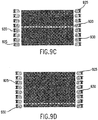
- Fig. 9B schematically illustrates the third scan line 920 from the top of a camera active in its raster scan process. Only the LEDs 925 that would not directly reflect into the active scan line are illuminated at this time. LEDs 930 that would create direct reflection are not illuminated. Accordingly, only indirect illumination is provided (i.e. no direct reflection) to the portion of the target observed by the third scan line of the camera.
- Fig. 9C illustrates the same camera with the raster scan active for the eleventh scan line 925 from the top. Again, the illuminated LEDs 925 have changed to ensure that the target area observed by the eleventh scan line does not have any direct reflections and while providing even illumination.
- Fig. 9D illustrates the same camera with the raster scan active for the twenty-second scan line 925 from the top. In this position, the illuminated LEDs 925 are near the top to ensure no direct reflections and even illumination.
- While synchronized illumination does substantially eliminate direct reflection noise caused by scanner internal light sources, this technique does not address external illumination noise (e.g. direct reflection) introduced by the ambient environment.
- the brightness of the scanner's internal lighting is increased to reduce the camera's overall sensitivity to light. Such modification can reduce the camera's susceptibility to less intense ambient lighting that may be present.
- increased scanner lighting intensity may be combined with other techniques of the present invention, such as those previously discussed, to even further eliminate ambient environment light noise.
- an improved scanner design is provided by including a monochromatic or near monochromatic light source (e.g., LED) that is coupled with a narrow band filter placed in front of the camera as illustrated schematically in Fig. 10 .
- a monochromatic or near monochromatic light source e.g., LED
- a narrow band filter placed in front of the camera as illustrated schematically in Fig. 10 .
- different color light sources e.g., red, green, blue
- the camera can be programmed to first capture one frame with the scanner's lights extinguished. Therefore, any light readings that are recorded in this frame represent the environment's ambient light noise contribution. The average magnitude of the intensities of all of the camera's red, blue, and green pixels can then be compared. The color with the lowest average reading is selected for illumination and processing, since it represents the lowest light level of the environmental noise.
- the scanner would automatically turn on its green LEDs for illumination and only use the camera's green pixels for processing of the document.
- red, blue, and green pixel filters present on any color camera and the red, blue, and green LEDs built into the scanner would function as a dynamic filter to enhance the signal to noise ratio of the scanner's light source to its environment. It should be noted that these selective spectrum techniques of dynamic signal to noise reduction require a camera having sufficient pixel density to permit decoding the document using only one pixel color type.
- a majority of the noise sources inherent in camera scanning designs is reduced or even eliminated by incorporating two (or more) cameras that have overlapping fields of view of the same platen. If the two cameras' fields of view are arranged such that they are not completely overlapping, this technique also has the added advantage of minimizing the enclosure volume required for the scanning area.
- Figs. 11A through 11C illustrate a lottery terminal 1100 with an open scanning access area 1105 in the front.
- Terminal 1100 utilizes, by way of example, two 1.3 megapixel cameras 1110 and 1115 along with a mirror 1120 to provide a large scan 7.1 x 5.4 inches (181 x 136 mm) field of view with 280 dpi resolution.
- the overlap between the two cameras 1110 and 1115 can be processed digitally to either eliminate the overlap area of one of the two cameras or process both camera overlap image areas to achieve a composite image.
- this embodiment of the present invention provides a larger scanning area with relatively high camera resolution in a small enclosure using inexpensive cameras.
- the scan area covered by two relatively low resolution cameras e.g., .1.3 Megapixel
- Another advantage of a small overlap with two cameras is that a large scan area can be processed in less time (about half the time) required by a single camera processing the same area (i.e., parallel processing between the two cameras). With the exception of low lighting level situations or when digital preprocessing of the image is employed (discussed below), this advantage may be minimized as improvements in scanner cameras increase.
- the resulting composite image can then be evaluated with digital processing techniques to accomplish one or more of the following: a) substantially or completely eliminate glare (direct reflections) from all sources; b) reduce errors induced by a bent (or bowed) document; c) reduce errors from a platen and camera not being parallel; and d) enable multi-spectral scanning of the same document at the same time.
- glare direct reflections
- c reduce errors from a platen and camera not being parallel
- d enable multi-spectral scanning of the same document at the same time.
- glare is a direct reflection of a light source to the camera lens, and glare can make it impossible for the scanner to read portions of a document.
- glare is a direct reflection of a light source to the camera lens
- most sources of glare would not directly reflect into both cameras at the same time - assuming the two cameras are mounted side-by-side as shown in Figs. 11A through 11C .
- This mounting arrangement means that, for the most part, glare will appear on different areas of the document from the perspective of the two cameras.
- a composite image can be constructed that is virtually glare-free.
- this composite imaging method of glare reduction can be used in conjunction with other methods previously discussed (e.g., three sided enclosure, synchronized lighting, etc.)
- this composite imaging method can be used to reduce the scanner's dependency on some of these methods - e.g. to allow for a more open scanner enclosure.
- Bent document error results when the actual and perceived location of imagery on a bent or bowed document do not coincide. If the bent portion of the document is within the field of view of both side-by-side cameras, the resulting parallax shift of the same point on a document from one camera to the other can be used to digitally normalize the point's location on a virtual flat platen.
- the term "parallax shift” means measuring the differences in optical distortion as perceived by the two parallel cameras mounted along the same baseline. These differences in optical distortion can then be triangulated between the two cameras allowing a virtual ideal image (i.e., an image without the distortions) to be digitally constructed. This correlation and corresponding correction is particularly advantageous for documents, like bet slips, where the location of a mark on the two-dimensional document conveys information.
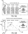
- Figs. 14A and 14B illustrate images of a typical bet slip aligned flat on the platen.
- the grid locations 1400 that have been filled in with a pen denote the numbers that the player desires for "Choices 1, 2, and 3" - e.g., the player's selection for Choice 1 (1405) is "657029" as shown in Fig. 14A.
- Fig. 14A illustrates the bet slip as it would appear in normal, white, light.
- Fig. 14B illustrates how the same bet slip would appear under red light illumination. This type of selective illumination filtering is widely known in the art and is used to eliminate the background for digital processing of only relevant data.
- the terminal's processor only need identify preprinted clock marks 1410 and the marks made by the consumer 1400 to deduce the numbers selected on a virtual grid.
- Fig. 14B shows virtual grid lines 1415 for the second number 1420 selected by the player in Choice 1 and the sixth number 1425 in Choice 3. This process works well provided the bet slip remains flat and parallel to the camera so that the perpendicular virtual grid overlay accurately maps the surface of the bet slip. However, in the event of a warped bet slip or a non-parallel platen, the perpendicular virtual grid overlay can convey incorrect information as illustrated in Fig. 15 .
- edge of ticket mapping or measuring of the distortion of the clock marks can be attempted with a single camera to compensate for warped distortion, it is extremely difficult to deduce all of the nuances of a three-dimensional surface with a single camera perspective.
- a better way is to map the differences between two cameras' perspectives (i.e., parallax shift) to deduce the amount and type of distortion in a non-flat/non-parallel document. This difference in perspectives can be analyzed and corrected through a wide variety of mathematical tools including principles of mapping, trigonometry, trilateration, etc. Mapping will be discussed herein and it should be understood that one of skill in the art, using the teachings disclosed herein, will be able to apply other mathematical tools to this problem.
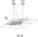
- Fig. 16 illustrates a two-camera scanning system with differing perspectives of a point D on the virtual plane (i.e., perfectly parallel and flat relative to cameras A and B ).
- points A' and B' represent the points on the virtual plane directly beneath the center pixels of cameras A and B respectively.
- the line segment C represents the distance between the center of cameras A and B and therefore accounts for the difference in perspective between the two cameras.
- the differences in the two cameras perspectives can be mapped directly to the virtual plane as different points of origin - i.e., point A' for camera A and point B' for camera B . Notice how these two differing points of origin create different reference coordinates for any arbitrary point D on the virtual plane even if D is selected such that the angle to D from the line segment A'B' on the virtual plane is approximately the same from both points of origin.
- any pixel (point) containing a dot of information will have different coordinates on each camera.
- the virtual plane is, by definition, perfectly flat and parallel to the two cameras there exists a mapping function to equate any pixel with information from camera A to camera B and vice versa.
- point D as seen from the perspective of camera A has orthogonal grid coordinates 8,9 ; but, the same point D has grid coordinates - 5,9 from the perspective of camera B .
- This idealized virtual plane can then be used to normalize a common dot of information that is observed by the two cameras on a warped or non-parallel document.
- the a priori mapping function between the two cameras would dictate that if a point D was observed by camera A at coordinates 8,9 then the same reference point D should be located at -5,9 on camera B's coordinate system. If the point was found to have different coordinates on camera B then -5,9; the difference would be attributable to either a warped (i.e., not flat) document, or a non-parallel plane, or a combination of the two.
- a mapping function e.g., Transverse Mercator projection
- Transverse Mercator projection can be used to normalize the dot's location on both coordinate systems A and B to the virtual plane as represented in Fig. 18 . Accordingly, under some circumstances, the image error induced by a bent document can be reduced by comparing the images of two side-by-side mounted cameras. Such comparison could be performed automatically by software, for example.
- Nonparallel platen/camera error can also cause offsets between the perceived and actual position of target document features as previously discussed. Again, the parallax shift between the two side-by-side camera perspectives can be used to digitally correct for the nonparallel platen and camera with the methodologies previously discussed. However, in the case of a nonparallel platen/camera (as opposed to the "bent document" condition) the source of error is the scanner itself. In another exemplary technique of the present invention, a permanent digital correction factor can be automatically computed by scanning a precision array of points printed on a special calibration document.
- the selective spectrum techniques previously discussed can be incorporated to provide each camera in the embodiments of Figs. 11A through 11C with a different bandpass filter.
- two different bands of light may be scanned at the same time.
- Such an arrangement could be used to help eliminate noise or also to authenticate a document.
- a document could be viewed both in white light and infrared at the same time with a taggant added to the document that uses white light to trigger fluorescence in the infrared band.
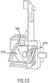
- the multi-spectral scanning technique does not require two cameras to be side-by-side. More specifically, the cameras could be mounted in the same optical path with a beam splitter sending a portion of the reflected light to each camera as shown in Fig. 12 , which depicts two cameras 1200 and 1210 along with a partially silvered mirror 1215.
- this shared optical path/beam splitter design likely will not work for any technique requiring different perspective or parallax shift for normalization.
- a scanner mounted DSP can provide the low level interface to the camera chip(s) and coordinate the raster scan as well as other parameters - e.g., exposure.
- the DSP's utility can be further enhanced if it is programmed to coordinate light synchronization; selective red, green, blue pixel filtering (previously discussed); or coordination and synchronization of dual cameras - all as previously discussed.
- the DSP can further reduce the burden on the primary processor by performing imaging preprocessing, which may include, for example 1) rotating and cropping the scanned image to only provide the primary processor with data from the actual document; 2) detecting overlapping documents - i.e. cropping and only providing image data for the document on the top; 3) compressing the scanned image; 4) transmitting only the information necessary for the task at hand; and/or 5) detecting direct reflections by, for example, detecting saturated pixels in the camera (full scale readings) and passing a warning message to the primary processor to alert the human operator.
- imaging preprocessing may include, for example 1) rotating and cropping the scanned image to only provide the primary processor with data from the actual document; 2) detecting overlapping documents - i.e. cropping and only providing image data for the document on the top; 3) compressing the scanned image; 4) transmitting only the information necessary for the task at hand; and/or 5) detecting direct reflections by, for example, detecting saturated pixels in the camera (full scale readings)
- yet another exemplary technique of the present invention provides a method for aligning on-line tickets for branding and allowing their digital image to be captured by a scanner.
- Branding is a concept used in the lottery industry to permanently mark a submitted on-line ticket (receipt) for a completed drawing. Once the submitted ticket is verified as a winner, the branding system prints "PAID" (or words to the same effect) on the ticket's surface, usually by using a thermal print head. Branding can be used for other purposes in the lottery industry, like printing "CANCELED” on tickets printed by mistake. Regardless, in each case the process is substantially the same. Once the ticket is verified (i.e., barcode or other data read from it), a secondary printing process overprints wording or other symbology to indicate a change of status for the ticket.
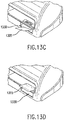
- a branding mechanism 1300 e.g. branding thermal print head 1305 and motor 1310 to move ticket 1315
- Terminal 1320 uses the same previously described two dimensional scanning system with cameras 1325 to read the ticket's barcode.
- the human operator places the submitted ticket 1315, barcode first, into an input slot 1330 below the platen.
- Motor 1310 advances ticket 1315 so that the ticket 1315 and its barcode emerge onto the platen where it is scanned ( Fig. 13D .
- the branding mechanism By mounting the branding mechanism beneath the platen with a separate input slot 1330, the human operator approaches the same area he or she uses for all other transactions.
- the ticket path is illustrated in Figure 13B . Assuming the ticket's barcode decodes to valid information, the appropriate branded status is then printed on the part of the ticket 1315 remaining in the mechanism and the ticket 1315 is ejected onto the platen. Conversely, if the barcode decodes to invalid information or cannot be decoded, the mechanism reverses the motor and the ticket 1315 is backed out of the input slot 1330.
Applications Claiming Priority (3)
| Application Number | Priority Date | Filing Date | Title |
|---|---|---|---|
| US96658207P | 2007-08-29 | 2007-08-29 | |
| US12/200,367 US8199370B2 (en) | 2007-08-29 | 2008-08-28 | Enhanced scanner design |
| EP08798944.8A EP2185256B1 (de) | 2007-08-29 | 2008-08-29 | Verbessertes abtastdesign |
Related Parent Applications (1)
| Application Number | Title | Priority Date | Filing Date |
|---|---|---|---|
| EP08798944.8A Division EP2185256B1 (de) | 2007-08-29 | 2008-08-29 | Verbessertes abtastdesign |
Publications (2)
| Publication Number | Publication Date |
|---|---|
| EP3177002A2 true EP3177002A2 (de) | 2017-06-07 |
| EP3177002A3 EP3177002A3 (de) | 2017-06-21 |
Family
ID=39876446
Family Applications (2)
| Application Number | Title | Priority Date | Filing Date |
|---|---|---|---|
| EP08798944.8A Active EP2185256B1 (de) | 2007-08-29 | 2008-08-29 | Verbessertes abtastdesign |
| EP17151477.1A Withdrawn EP3177002A3 (de) | 2007-08-29 | 2008-08-29 | Verbessertes abtastdesign |
Family Applications Before (1)
| Application Number | Title | Priority Date | Filing Date |
|---|---|---|---|
| EP08798944.8A Active EP2185256B1 (de) | 2007-08-29 | 2008-08-29 | Verbessertes abtastdesign |
Country Status (8)
| Country | Link |
|---|---|
| US (2) | US8199370B2 (de) |
| EP (2) | EP2185256B1 (de) |
| CN (3) | CN103873733B (de) |
| AU (1) | AU2008293402B2 (de) |
| CA (1) | CA2697788C (de) |
| ES (1) | ES2618495T3 (de) |
| MX (1) | MX2010002370A (de) |
| WO (1) | WO2009029772A1 (de) |
Families Citing this family (21)
| Publication number | Priority date | Publication date | Assignee | Title |
|---|---|---|---|---|
| WO2008028674A2 (en) * | 2006-09-08 | 2008-03-13 | Exbiblio B.V. | Optical scanners, such as hand-held optical scanners |
| US8269855B2 (en) * | 2009-01-15 | 2012-09-18 | Essence Security International Ltd. | Narrow bandwidth illumination image processing system and method |
| US8622302B2 (en) * | 2009-03-17 | 2014-01-07 | Datalogic ADC, Inc. | Systems and methods for compensating for fixed pattern noise |
| EP2409260A1 (de) * | 2009-03-17 | 2012-01-25 | Scientific Games Holdings Limited | Optische signatur zur ermöglichung von bildkorrektur |
| US8649076B2 (en) * | 2009-07-30 | 2014-02-11 | Hewlett-Packard Development Company, L.P. | Calibrating field uniformity |
| ITTO20110261A1 (it) * | 2011-03-25 | 2012-09-26 | St Microelectronics Srl | "apparecchio scanner, procedimento e prodotto informatico relativi" |
| NL2006698C2 (en) * | 2011-04-29 | 2012-10-30 | Optelec Dev B V | Portable magnifying camera. |
| WO2012164686A1 (ja) * | 2011-05-31 | 2012-12-06 | 楽天株式会社 | 画像処理装置、画像処理方法、プログラム及び記録媒体 |
| KR20140111341A (ko) | 2012-01-09 | 2014-09-18 | 퀄컴 인코포레이티드 | Ocr 캐시 업데이트 |
| USD685372S1 (en) * | 2012-11-30 | 2013-07-02 | Atiz Innovation Co., Ltd. | Document scanning and visualization system |
| US8559063B1 (en) * | 2012-11-30 | 2013-10-15 | Atiz Innovation Co., Ltd. | Document scanning and visualization system using a mobile device |
| US20140153066A1 (en) * | 2012-11-30 | 2014-06-05 | Sarasin Booppanon | Document scanning system with true color indicator |
| US9742952B2 (en) | 2014-08-12 | 2017-08-22 | Scanner Bin, LLC | Image scanning and object storage |
| EP3198525A4 (de) * | 2014-09-24 | 2018-05-23 | Atkinson, Don | Auswertungsvorrichtung mit gleichförmiger beleuchtung und datenerfassung |
| US9619686B2 (en) | 2015-03-10 | 2017-04-11 | Conduent Business Services, Llc | Printed tag information recognition using multi-pose illumination to mitigate glare |
| US20170209783A1 (en) * | 2016-01-22 | 2017-07-27 | Hydra Management Llc | Scratch-off games with collectible variable reveal feature |
| FR3064782B1 (fr) | 2017-03-30 | 2019-04-05 | Idemia Identity And Security | Procede d'analyse d'un document structure susceptible d'etre deforme |
| US10881949B2 (en) * | 2019-04-24 | 2021-01-05 | Igt Global Solutions Corporation | Lottery ticket pack verification system and method |
| RU2723409C1 (ru) * | 2019-08-23 | 2020-06-11 | Закрытое акционерное общество "ЛЕТА" | Сканер документов, удостоверяющих личность |
| FR3109048B1 (fr) * | 2020-04-06 | 2022-04-15 | Idemia Identity & Security France | procédé et dispositif d’imagerie de documents |
| CN111783768B (zh) * | 2020-07-07 | 2023-12-01 | 科大讯飞股份有限公司 | 一种扫描笔 |
Family Cites Families (33)
| Publication number | Priority date | Publication date | Assignee | Title |
|---|---|---|---|---|
| US4731661A (en) * | 1984-11-16 | 1988-03-15 | Sharp Kabushiki Kaisha | Color document reader with white balance adjuster for determining light emission periods for a plurality of different-colored light sources and corresponding integration times for a light sensor by reading a white reference area |
| US5268752A (en) * | 1989-06-12 | 1993-12-07 | Semiconductor Energy Laboratory Co., Ltd. | Image sensing device utilizing synchronized LEDs and light sensors |
| CA1321026C (en) * | 1989-09-28 | 1993-08-03 | Arny I. Sokoloff | Method and apparatus for optically reading pre-printed survey pages |
| US5109153A (en) * | 1990-04-17 | 1992-04-28 | Johnsen Edward L | Flash imaging and voidable articles |
| US5619254A (en) * | 1995-04-11 | 1997-04-08 | Mcnelley; Steve H. | Compact teleconferencing eye contact terminal |
| JP3406140B2 (ja) * | 1996-01-18 | 2003-05-12 | シャープ株式会社 | カラー画像読み取り装置 |
| AU702209B2 (en) * | 1996-07-16 | 1999-02-18 | Roche Diagnostics Gmbh | Analytical system with means for detecting too small sample volumes |
| US5798849A (en) * | 1996-11-05 | 1998-08-25 | Mustek Systems Inc. | Multilevel light source device |
| US6394952B1 (en) * | 1998-02-03 | 2002-05-28 | Adeza Biomedical Corporation | Point of care diagnostic systems |
| US5974168A (en) * | 1998-04-16 | 1999-10-26 | International Business Machines Corporation | Acquiring bump maps from curved objects |
| US6155491A (en) * | 1998-05-29 | 2000-12-05 | Welch Allyn Data Collection, Inc. | Lottery game ticket processing apparatus |
| CA2306515A1 (en) * | 2000-04-25 | 2001-10-25 | Inspeck Inc. | Internet stereo vision, 3d digitizing, and motion capture camera |
| US6439743B1 (en) * | 2000-10-05 | 2002-08-27 | Power Signal Technologies Inc. | Solid state traffic light apparatus having a cover including an integral lens |
| GB2372391A (en) | 2001-02-16 | 2002-08-21 | Hewlett Packard Co | Removal of specular reflection |
| US7023588B2 (en) | 2001-09-10 | 2006-04-04 | Kabushiki Kaisha Toshiba | Image reading apparatus |
| EP1452010A2 (de) * | 2001-11-23 | 2004-09-01 | Oce Document Technologies Gmbh | Einrichtung und verfahren zum abtasten einer vorlage unter anwendung einer hebe- und drehbewegung einer kamera |
| CN1469299A (zh) * | 2002-07-16 | 2004-01-21 | 力捷电脑股份有限公司 | 具有双面扫描功能的扫描仪组及其中的光源控制方法 |
| CN2587188Y (zh) * | 2002-11-10 | 2003-11-26 | 柯育华 | 一种脆糖块 |
| CN2622726Y (zh) * | 2003-01-24 | 2004-06-30 | 力捷电脑股份有限公司 | 扫描头的光学总成 |
| US20050029352A1 (en) * | 2003-08-08 | 2005-02-10 | Spears Kurt E. | System and method for automatic correction of illumination noise caused by ambient light |
| US7640691B2 (en) * | 2004-02-11 | 2010-01-05 | Philip B Karcher | Dual sight scope system and method |
| WO2005088955A1 (ja) * | 2004-03-16 | 2005-09-22 | Canon Components, Inc. | カラーイメージセンサユニット及び前記センサユニットを用いた画像読み取り装置及びその制御方法 |
| JP2007263563A (ja) * | 2004-06-03 | 2007-10-11 | Matsushita Electric Ind Co Ltd | カメラモジュール |
| JP4663407B2 (ja) * | 2004-06-11 | 2011-04-06 | キヤノン株式会社 | 記録材判別装置および方法 |
| US7248280B2 (en) * | 2004-06-16 | 2007-07-24 | Lexmark International, Inc. | Laser scanner having reduced air currents |
| JP4211703B2 (ja) * | 2004-07-23 | 2009-01-21 | セイコーエプソン株式会社 | 画像読み取り装置 |
| DE602006008587D1 (de) * | 2005-03-14 | 2009-10-01 | Gtech Corp | System und verfahren zur verarbeitung von markierungen in einem formular |
| EP1764996A1 (de) * | 2005-09-20 | 2007-03-21 | Agfa Graphics N.V. | Verfahren und Apparat für automatische Ausrichtung von Druckelementanordnungen |
| JP4821372B2 (ja) * | 2006-03-03 | 2011-11-24 | 富士ゼロックス株式会社 | 画像読み取り装置 |
| CN101150732B (zh) * | 2006-09-20 | 2010-08-11 | 王锦峰 | 用黑白相机拍摄彩色图像的成像方法和装置 |
| KR100874158B1 (ko) * | 2007-03-14 | 2008-12-15 | 주식회사 아이센스 | 전기화학적 바이오센서 및 이의 측정기 |
| CN101094299A (zh) * | 2007-06-29 | 2007-12-26 | Duplo(山东)办公设备有限公司 | 制版印刷一体机扫描方法及实现该方法的扫描机构 |
| US8119905B2 (en) * | 2007-11-03 | 2012-02-21 | Solfocus, Inc. | Combination non-imaging concentrator |
-
2008
- 2008-08-28 US US12/200,367 patent/US8199370B2/en active Active
- 2008-08-29 ES ES08798944.8T patent/ES2618495T3/es active Active
- 2008-08-29 WO PCT/US2008/074761 patent/WO2009029772A1/en active Application Filing
- 2008-08-29 AU AU2008293402A patent/AU2008293402B2/en active Active
- 2008-08-29 EP EP08798944.8A patent/EP2185256B1/de active Active
- 2008-08-29 MX MX2010002370A patent/MX2010002370A/es active IP Right Grant
- 2008-08-29 CN CN201410090106.5A patent/CN103873733B/zh active Active
- 2008-08-29 CN CN200880114430.9A patent/CN101883614B/zh not_active Expired - Fee Related
- 2008-08-29 EP EP17151477.1A patent/EP3177002A3/de not_active Withdrawn
- 2008-08-29 CN CN201410090583.1A patent/CN103861275B/zh active Active
- 2008-08-29 CA CA2697788A patent/CA2697788C/en active Active
-
2012
- 2012-06-12 US US13/494,279 patent/US8638479B2/en active Active
Non-Patent Citations (1)
| Title |
|---|
| None |
Also Published As
| Publication number | Publication date |
|---|---|
| CA2697788A1 (en) | 2009-03-05 |
| US20090059316A1 (en) | 2009-03-05 |
| EP2185256A1 (de) | 2010-05-19 |
| US20120250118A1 (en) | 2012-10-04 |
| US8199370B2 (en) | 2012-06-12 |
| WO2009029772A1 (en) | 2009-03-05 |
| CN101883614A (zh) | 2010-11-10 |
| AU2008293402B2 (en) | 2011-11-24 |
| ES2618495T3 (es) | 2017-06-21 |
| EP2185256B1 (de) | 2017-01-18 |
| EP3177002A3 (de) | 2017-06-21 |
| US8638479B2 (en) | 2014-01-28 |
| AU2008293402A1 (en) | 2009-03-05 |
| CN101883614B (zh) | 2014-04-02 |
| MX2010002370A (es) | 2010-06-25 |
| CN103861275B (zh) | 2017-12-12 |
| CN103861275A (zh) | 2014-06-18 |
| CN103873733B (zh) | 2017-04-12 |
| CN103873733A (zh) | 2014-06-18 |
| CA2697788C (en) | 2016-05-10 |
Similar Documents
| Publication | Publication Date | Title |
|---|---|---|
| US8638479B2 (en) | Enhanced scanner design | |
| JP3892407B2 (ja) | 撮影装置 | |
| US6498867B1 (en) | Method and apparatus for differential illumination image-capturing and defect handling | |
| US8844819B2 (en) | Reading device | |
| GB2302434A (en) | Data symbol reading system | |
| US8854703B2 (en) | Document reading device | |
| CN109565531A (zh) | 信息读取装置 | |
| WO2012042887A1 (ja) | 帳票読取装置 | |
| JP4473933B1 (ja) | 読取装置 | |
| AU2012244240B2 (en) | Enhanced scanner design | |
| US20080285094A1 (en) | Uniform illumination for camera based scanning devices | |
| KR101460686B1 (ko) | 홀로그램 처리기능을 가지는 스캔 장치 및 스캔 방법 | |
| KR101433001B1 (ko) | 고품질 스캐너 | |
| KR101460685B1 (ko) | 초소형 스캐너 | |
| WO2023175031A1 (en) | Document reader with improved illumination | |
| JP2020119451A (ja) | 情報読取装置の使用方法 | |
| JP2009253318A (ja) | 非接触スキャナ装置 | |
| JP2010200186A (ja) | 読取装置 |
Legal Events
| Date | Code | Title | Description |
|---|---|---|---|
| PUAL | Search report despatched |
Free format text: ORIGINAL CODE: 0009013 |
|
| AC | Divisional application: reference to earlier application |
Ref document number: 2185256 Country of ref document: EP Kind code of ref document: P |
|
| AK | Designated contracting states |
Kind code of ref document: A2 Designated state(s): AT BE BG CH CY CZ DE DK EE ES FI FR GB GR HR HU IE IS IT LI LT LU LV MC MT NL NO PL PT RO SE SI SK TR |
|
| PUAI | Public reference made under article 153(3) epc to a published international application that has entered the european phase |
Free format text: ORIGINAL CODE: 0009012 |
|
| AK | Designated contracting states |
Kind code of ref document: A3 Designated state(s): AT BE BG CH CY CZ DE DK EE ES FI FR GB GR HR HU IE IS IT LI LT LU LV MC MT NL NO PL PT RO SE SI SK TR |
|
| RIC1 | Information provided on ipc code assigned before grant |
Ipc: H04N 1/00 20060101AFI20170516BHEP Ipc: A63F 9/24 20060101ALI20170516BHEP Ipc: H04N 1/195 20060101ALI20170516BHEP Ipc: A63F 3/06 20060101ALI20170516BHEP Ipc: B60R 1/08 20060101ALI20170516BHEP |
|
| 17P | Request for examination filed |
Effective date: 20171221 |
|
| RBV | Designated contracting states (corrected) |
Designated state(s): AT BE BG CH CY CZ DE DK EE ES FI FR GB GR HR HU IE IS IT LI LT LU LV MC MT NL NO PL PT RO SE SI SK TR |
|
| 17Q | First examination report despatched |
Effective date: 20180803 |
|
| STAA | Information on the status of an ep patent application or granted ep patent |
Free format text: STATUS: THE APPLICATION IS DEEMED TO BE WITHDRAWN |
|
| 18D | Application deemed to be withdrawn |
Effective date: 20181214 |