EP3176639B1 - Element für elektrofotografie, prozesskassette und elektrofotografische vorrichtung - Google Patents
Element für elektrofotografie, prozesskassette und elektrofotografische vorrichtung Download PDFInfo
- Publication number
- EP3176639B1 EP3176639B1 EP16200001.2A EP16200001A EP3176639B1 EP 3176639 B1 EP3176639 B1 EP 3176639B1 EP 16200001 A EP16200001 A EP 16200001A EP 3176639 B1 EP3176639 B1 EP 3176639B1
- Authority
- EP
- European Patent Office
- Prior art keywords
- formula
- group
- less
- carbon atoms
- electro
- Prior art date
- Legal status (The legal status is an assumption and is not a legal conclusion. Google has not performed a legal analysis and makes no representation as to the accuracy of the status listed.)
- Active
Links
- 238000000034 method Methods 0.000 title claims description 31
- 230000008569 process Effects 0.000 title claims description 18
- 229920005989 resin Polymers 0.000 claims description 81
- 239000011347 resin Substances 0.000 claims description 81
- 229920001296 polysiloxane Polymers 0.000 claims description 57
- 125000002887 hydroxy group Chemical group [H]O* 0.000 claims description 56
- -1 isocyanate compound Chemical class 0.000 claims description 52
- 125000004432 carbon atom Chemical group C* 0.000 claims description 50
- 229920002803 thermoplastic polyurethane Polymers 0.000 claims description 49
- 150000003077 polyols Chemical class 0.000 claims description 44
- 229920005862 polyol Polymers 0.000 claims description 43
- 125000004435 hydrogen atom Chemical group [H]* 0.000 claims description 30
- 125000000217 alkyl group Chemical group 0.000 claims description 28
- 239000000470 constituent Substances 0.000 claims description 26
- 239000000126 substance Substances 0.000 claims description 18
- 239000012948 isocyanate Substances 0.000 claims description 13
- 125000005843 halogen group Chemical group 0.000 claims description 12
- 125000003118 aryl group Chemical group 0.000 claims description 11
- 150000002148 esters Chemical class 0.000 claims description 9
- 125000002947 alkylene group Chemical group 0.000 claims description 6
- RTZKZFJDLAIYFH-UHFFFAOYSA-N ether Substances CCOCC RTZKZFJDLAIYFH-UHFFFAOYSA-N 0.000 claims description 6
- 125000005647 linker group Chemical group 0.000 claims description 5
- 239000011203 carbon fibre reinforced carbon Substances 0.000 claims description 2
- 239000010410 layer Substances 0.000 description 97
- 150000001875 compounds Chemical class 0.000 description 35
- 239000000463 material Substances 0.000 description 31
- 239000000243 solution Substances 0.000 description 28
- 230000000052 comparative effect Effects 0.000 description 24
- 238000011156 evaluation Methods 0.000 description 24
- 238000005259 measurement Methods 0.000 description 21
- 229920003023 plastic Polymers 0.000 description 20
- 239000004033 plastic Substances 0.000 description 20
- NIXOWILDQLNWCW-UHFFFAOYSA-M Acrylate Chemical compound [O-]C(=O)C=C NIXOWILDQLNWCW-UHFFFAOYSA-M 0.000 description 19
- 239000011248 coating agent Substances 0.000 description 19
- 238000000576 coating method Methods 0.000 description 19
- 238000013329 compounding Methods 0.000 description 17
- 235000013870 dimethyl polysiloxane Nutrition 0.000 description 17
- 229920000435 poly(dimethylsiloxane) Polymers 0.000 description 17
- 239000002904 solvent Substances 0.000 description 17
- 239000004205 dimethyl polysiloxane Substances 0.000 description 16
- 150000003254 radicals Chemical class 0.000 description 14
- ZWEHNKRNPOVVGH-UHFFFAOYSA-N 2-Butanone Chemical compound CCC(C)=O ZWEHNKRNPOVVGH-UHFFFAOYSA-N 0.000 description 13
- 150000002009 diols Chemical class 0.000 description 13
- WYURNTSHIVDZCO-UHFFFAOYSA-N Tetrahydrofuran Chemical compound C1CCOC1 WYURNTSHIVDZCO-UHFFFAOYSA-N 0.000 description 12
- 230000015572 biosynthetic process Effects 0.000 description 12
- 229910052731 fluorine Inorganic materials 0.000 description 12
- IQPQWNKOIGAROB-UHFFFAOYSA-N isocyanate group Chemical group [N-]=C=O IQPQWNKOIGAROB-UHFFFAOYSA-N 0.000 description 12
- 239000007787 solid Substances 0.000 description 12
- 239000003795 chemical substances by application Substances 0.000 description 11
- 238000006116 polymerization reaction Methods 0.000 description 11
- 239000006229 carbon black Substances 0.000 description 10
- 125000000118 dimethyl group Chemical group [H]C([H])([H])* 0.000 description 10
- 229920001971 elastomer Polymers 0.000 description 10
- 239000005060 rubber Substances 0.000 description 10
- 239000010935 stainless steel Substances 0.000 description 10
- 229910001220 stainless steel Inorganic materials 0.000 description 10
- 238000012546 transfer Methods 0.000 description 10
- 238000004140 cleaning Methods 0.000 description 9
- 239000000203 mixture Substances 0.000 description 9
- UPMLOUAZCHDJJD-UHFFFAOYSA-N 4,4'-Diphenylmethane Diisocyanate Chemical compound C1=CC(N=C=O)=CC=C1CC1=CC=C(N=C=O)C=C1 UPMLOUAZCHDJJD-UHFFFAOYSA-N 0.000 description 8
- XLOMVQKBTHCTTD-UHFFFAOYSA-N Zinc monoxide Chemical compound [Zn]=O XLOMVQKBTHCTTD-UHFFFAOYSA-N 0.000 description 8
- 229920002379 silicone rubber Polymers 0.000 description 8
- 238000003786 synthesis reaction Methods 0.000 description 8
- 238000012360 testing method Methods 0.000 description 8
- 125000000391 vinyl group Chemical group [H]C([*])=C([H])[H] 0.000 description 8
- LYCAIKOWRPUZTN-UHFFFAOYSA-N Ethylene glycol Chemical compound OCCO LYCAIKOWRPUZTN-UHFFFAOYSA-N 0.000 description 7
- YCKRFDGAMUMZLT-UHFFFAOYSA-N Fluorine atom Chemical compound [F] YCKRFDGAMUMZLT-UHFFFAOYSA-N 0.000 description 7
- 239000004721 Polyphenylene oxide Substances 0.000 description 7
- 238000006243 chemical reaction Methods 0.000 description 7
- 239000010419 fine particle Substances 0.000 description 7
- 239000011737 fluorine Substances 0.000 description 7
- 229910052751 metal Inorganic materials 0.000 description 7
- 239000002184 metal Substances 0.000 description 7
- 229920000570 polyether Polymers 0.000 description 7
- 238000007639 printing Methods 0.000 description 7
- 239000004945 silicone rubber Substances 0.000 description 7
- 239000002344 surface layer Substances 0.000 description 7
- XLYOFNOQVPJJNP-UHFFFAOYSA-N water Chemical compound O XLYOFNOQVPJJNP-UHFFFAOYSA-N 0.000 description 7
- WFDIJRYMOXRFFG-UHFFFAOYSA-N Acetic anhydride Chemical compound CC(=O)OC(C)=O WFDIJRYMOXRFFG-UHFFFAOYSA-N 0.000 description 6
- VTYYLEPIZMXCLO-UHFFFAOYSA-L Calcium carbonate Chemical compound [Ca+2].[O-]C([O-])=O VTYYLEPIZMXCLO-UHFFFAOYSA-L 0.000 description 6
- YXFVVABEGXRONW-UHFFFAOYSA-N Toluene Chemical compound CC1=CC=CC=C1 YXFVVABEGXRONW-UHFFFAOYSA-N 0.000 description 6
- 239000000654 additive Substances 0.000 description 6
- 239000002390 adhesive tape Substances 0.000 description 6
- 238000011088 calibration curve Methods 0.000 description 6
- 239000006258 conductive agent Substances 0.000 description 6
- 230000000694 effects Effects 0.000 description 6
- 125000001153 fluoro group Chemical group F* 0.000 description 6
- 239000011521 glass Substances 0.000 description 6
- 239000003999 initiator Substances 0.000 description 6
- 150000002500 ions Chemical class 0.000 description 6
- 239000005056 polyisocyanate Substances 0.000 description 6
- 229920001228 polyisocyanate Polymers 0.000 description 6
- CXMXRPHRNRROMY-UHFFFAOYSA-N sebacic acid Chemical compound OC(=O)CCCCCCCCC(O)=O CXMXRPHRNRROMY-UHFFFAOYSA-N 0.000 description 6
- 229920000459 Nitrile rubber Polymers 0.000 description 5
- VYPSYNLAJGMNEJ-UHFFFAOYSA-N Silicium dioxide Chemical compound O=[Si]=O VYPSYNLAJGMNEJ-UHFFFAOYSA-N 0.000 description 5
- 239000010408 film Substances 0.000 description 5
- 125000002496 methyl group Chemical group [H]C([H])([H])* 0.000 description 5
- 239000011369 resultant mixture Substances 0.000 description 5
- IJGRMHOSHXDMSA-UHFFFAOYSA-N Atomic nitrogen Chemical compound N#N IJGRMHOSHXDMSA-UHFFFAOYSA-N 0.000 description 4
- 0 C*1=*CC*C1 Chemical compound C*1=*CC*C1 0.000 description 4
- RYGMFSIKBFXOCR-UHFFFAOYSA-N Copper Chemical compound [Cu] RYGMFSIKBFXOCR-UHFFFAOYSA-N 0.000 description 4
- XEEYBQQBJWHFJM-UHFFFAOYSA-N Iron Chemical compound [Fe] XEEYBQQBJWHFJM-UHFFFAOYSA-N 0.000 description 4
- PXHVJJICTQNCMI-UHFFFAOYSA-N Nickel Chemical compound [Ni] PXHVJJICTQNCMI-UHFFFAOYSA-N 0.000 description 4
- 239000005062 Polybutadiene Substances 0.000 description 4
- HXBPYFMVGFDZFT-UHFFFAOYSA-N allyl isocyanate Chemical compound C=CCN=C=O HXBPYFMVGFDZFT-UHFFFAOYSA-N 0.000 description 4
- 229910052782 aluminium Inorganic materials 0.000 description 4
- XAGFODPZIPBFFR-UHFFFAOYSA-N aluminium Chemical compound [Al] XAGFODPZIPBFFR-UHFFFAOYSA-N 0.000 description 4
- 229910052802 copper Inorganic materials 0.000 description 4
- 239000010949 copper Substances 0.000 description 4
- FJKIXWOMBXYWOQ-UHFFFAOYSA-N ethenoxyethane Chemical compound CCOC=C FJKIXWOMBXYWOQ-UHFFFAOYSA-N 0.000 description 4
- 125000000524 functional group Chemical group 0.000 description 4
- 230000001771 impaired effect Effects 0.000 description 4
- 238000010907 mechanical stirring Methods 0.000 description 4
- 150000002739 metals Chemical class 0.000 description 4
- 229920002857 polybutadiene Polymers 0.000 description 4
- 230000002265 prevention Effects 0.000 description 4
- 239000011541 reaction mixture Substances 0.000 description 4
- 230000035484 reaction time Effects 0.000 description 4
- 238000011084 recovery Methods 0.000 description 4
- 239000002699 waste material Substances 0.000 description 4
- 239000011787 zinc oxide Substances 0.000 description 4
- VVQNEPGJFQJSBK-UHFFFAOYSA-N Methyl methacrylate Chemical compound COC(=O)C(C)=C VVQNEPGJFQJSBK-UHFFFAOYSA-N 0.000 description 3
- CTQNGGLPUBDAKN-UHFFFAOYSA-N O-Xylene Chemical compound CC1=CC=CC=C1C CTQNGGLPUBDAKN-UHFFFAOYSA-N 0.000 description 3
- HEMHJVSKTPXQMS-UHFFFAOYSA-M Sodium hydroxide Chemical compound [OH-].[Na+] HEMHJVSKTPXQMS-UHFFFAOYSA-M 0.000 description 3
- GWEVSGVZZGPLCZ-UHFFFAOYSA-N Titan oxide Chemical compound O=[Ti]=O GWEVSGVZZGPLCZ-UHFFFAOYSA-N 0.000 description 3
- ZMANZCXQSJIPKH-UHFFFAOYSA-N Triethylamine Chemical compound CCN(CC)CC ZMANZCXQSJIPKH-UHFFFAOYSA-N 0.000 description 3
- 150000001252 acrylic acid derivatives Chemical class 0.000 description 3
- 239000011230 binding agent Substances 0.000 description 3
- 229910000019 calcium carbonate Inorganic materials 0.000 description 3
- 229910052799 carbon Inorganic materials 0.000 description 3
- 239000011231 conductive filler Substances 0.000 description 3
- 239000003431 cross linking reagent Substances 0.000 description 3
- 238000003618 dip coating Methods 0.000 description 3
- 238000001035 drying Methods 0.000 description 3
- 125000001495 ethyl group Chemical group [H]C([H])([H])C([H])([H])* 0.000 description 3
- 150000002513 isocyanates Chemical class 0.000 description 3
- VLKZOEOYAKHREP-UHFFFAOYSA-N n-Hexane Chemical compound CCCCCC VLKZOEOYAKHREP-UHFFFAOYSA-N 0.000 description 3
- 239000012299 nitrogen atmosphere Substances 0.000 description 3
- 239000003921 oil Substances 0.000 description 3
- 125000000962 organic group Chemical group 0.000 description 3
- 239000003960 organic solvent Substances 0.000 description 3
- 239000002245 particle Substances 0.000 description 3
- VLTRZXGMWDSKGL-UHFFFAOYSA-N perchloric acid Chemical compound OCl(=O)(=O)=O VLTRZXGMWDSKGL-UHFFFAOYSA-N 0.000 description 3
- 229920000515 polycarbonate Polymers 0.000 description 3
- 239000004417 polycarbonate Substances 0.000 description 3
- 238000010526 radical polymerization reaction Methods 0.000 description 3
- YLQBMQCUIZJEEH-UHFFFAOYSA-N tetrahydrofuran Natural products C=1C=COC=1 YLQBMQCUIZJEEH-UHFFFAOYSA-N 0.000 description 3
- OGIDPMRJRNCKJF-UHFFFAOYSA-N titanium oxide Inorganic materials [Ti]=O OGIDPMRJRNCKJF-UHFFFAOYSA-N 0.000 description 3
- 239000008096 xylene Substances 0.000 description 3
- 125000003903 2-propenyl group Chemical group [H]C([*])([H])C([H])=C([H])[H] 0.000 description 2
- DSSAWHFZNWVJEC-UHFFFAOYSA-N 3-(ethenoxymethyl)heptane Chemical compound CCCCC(CC)COC=C DSSAWHFZNWVJEC-UHFFFAOYSA-N 0.000 description 2
- LJPCNSSTRWGCMZ-UHFFFAOYSA-N 3-methyloxolane Chemical compound CC1CCOC1 LJPCNSSTRWGCMZ-UHFFFAOYSA-N 0.000 description 2
- HMBNQNDUEFFFNZ-UHFFFAOYSA-N 4-ethenoxybutan-1-ol Chemical compound OCCCCOC=C HMBNQNDUEFFFNZ-UHFFFAOYSA-N 0.000 description 2
- SOGAXMICEFXMKE-UHFFFAOYSA-N Butylmethacrylate Chemical compound CCCCOC(=O)C(C)=C SOGAXMICEFXMKE-UHFFFAOYSA-N 0.000 description 2
- VYZAMTAEIAYCRO-UHFFFAOYSA-N Chromium Chemical compound [Cr] VYZAMTAEIAYCRO-UHFFFAOYSA-N 0.000 description 2
- 244000043261 Hevea brasiliensis Species 0.000 description 2
- CSNNHWWHGAXBCP-UHFFFAOYSA-L Magnesium sulfate Chemical compound [Mg+2].[O-][S+2]([O-])([O-])[O-] CSNNHWWHGAXBCP-UHFFFAOYSA-L 0.000 description 2
- CERQOIWHTDAKMF-UHFFFAOYSA-M Methacrylate Chemical compound CC(=C)C([O-])=O CERQOIWHTDAKMF-UHFFFAOYSA-M 0.000 description 2
- MZRVEZGGRBJDDB-UHFFFAOYSA-N N-Butyllithium Chemical compound [Li]CCCC MZRVEZGGRBJDDB-UHFFFAOYSA-N 0.000 description 2
- 239000004793 Polystyrene Substances 0.000 description 2
- UIIMBOGNXHQVGW-UHFFFAOYSA-M Sodium bicarbonate Chemical compound [Na+].OC([O-])=O UIIMBOGNXHQVGW-UHFFFAOYSA-M 0.000 description 2
- 235000021355 Stearic acid Nutrition 0.000 description 2
- QYKIQEUNHZKYBP-UHFFFAOYSA-N Vinyl ether Chemical class C=COC=C QYKIQEUNHZKYBP-UHFFFAOYSA-N 0.000 description 2
- 125000003647 acryloyl group Chemical group O=C([*])C([H])=C([H])[H] 0.000 description 2
- WNLRTRBMVRJNCN-UHFFFAOYSA-N adipic acid Chemical compound OC(=O)CCCCC(O)=O WNLRTRBMVRJNCN-UHFFFAOYSA-N 0.000 description 2
- 229910045601 alloy Inorganic materials 0.000 description 2
- 239000000956 alloy Substances 0.000 description 2
- 238000013459 approach Methods 0.000 description 2
- 239000007864 aqueous solution Substances 0.000 description 2
- 230000033228 biological regulation Effects 0.000 description 2
- 150000001642 boronic acid derivatives Chemical class 0.000 description 2
- WERYXYBDKMZEQL-UHFFFAOYSA-N butane-1,4-diol Chemical compound OCCCCO WERYXYBDKMZEQL-UHFFFAOYSA-N 0.000 description 2
- DKPFZGUDAPQIHT-UHFFFAOYSA-N butyl acetate Chemical compound CCCCOC(C)=O DKPFZGUDAPQIHT-UHFFFAOYSA-N 0.000 description 2
- 239000003990 capacitor Substances 0.000 description 2
- 239000003054 catalyst Substances 0.000 description 2
- 239000012295 chemical reaction liquid Substances 0.000 description 2
- 239000011651 chromium Substances 0.000 description 2
- 229910052804 chromium Inorganic materials 0.000 description 2
- 239000004020 conductor Substances 0.000 description 2
- 229920001577 copolymer Polymers 0.000 description 2
- 238000004132 cross linking Methods 0.000 description 2
- 125000002993 cycloalkylene group Chemical group 0.000 description 2
- 238000011161 development Methods 0.000 description 2
- 229910001873 dinitrogen Inorganic materials 0.000 description 2
- 238000006073 displacement reaction Methods 0.000 description 2
- 238000010438 heat treatment Methods 0.000 description 2
- HTDJPCNNEPUOOQ-UHFFFAOYSA-N hexamethylcyclotrisiloxane Chemical compound C[Si]1(C)O[Si](C)(C)O[Si](C)(C)O1 HTDJPCNNEPUOOQ-UHFFFAOYSA-N 0.000 description 2
- 239000001257 hydrogen Substances 0.000 description 2
- 229910052739 hydrogen Inorganic materials 0.000 description 2
- WGCNASOHLSPBMP-UHFFFAOYSA-N hydroxyacetaldehyde Natural products OCC=O WGCNASOHLSPBMP-UHFFFAOYSA-N 0.000 description 2
- 229910052742 iron Inorganic materials 0.000 description 2
- NIMLQBUJDJZYEJ-UHFFFAOYSA-N isophorone diisocyanate Chemical compound CC1(C)CC(N=C=O)CC(C)(CN=C=O)C1 NIMLQBUJDJZYEJ-UHFFFAOYSA-N 0.000 description 2
- 229920003049 isoprene rubber Polymers 0.000 description 2
- 239000007788 liquid Substances 0.000 description 2
- 230000014759 maintenance of location Effects 0.000 description 2
- 238000004519 manufacturing process Methods 0.000 description 2
- 229910044991 metal oxide Inorganic materials 0.000 description 2
- 150000004706 metal oxides Chemical class 0.000 description 2
- 239000000178 monomer Substances 0.000 description 2
- 125000004108 n-butyl group Chemical group [H]C([H])([H])C([H])([H])C([H])([H])C([H])([H])* 0.000 description 2
- 229920003052 natural elastomer Polymers 0.000 description 2
- 229920001194 natural rubber Polymers 0.000 description 2
- 229910052759 nickel Inorganic materials 0.000 description 2
- BDJRBEYXGGNYIS-UHFFFAOYSA-N nonanedioic acid Chemical compound OC(=O)CCCCCCCC(O)=O BDJRBEYXGGNYIS-UHFFFAOYSA-N 0.000 description 2
- QIQXTHQIDYTFRH-UHFFFAOYSA-N octadecanoic acid Chemical compound CCCCCCCCCCCCCCCCCC(O)=O QIQXTHQIDYTFRH-UHFFFAOYSA-N 0.000 description 2
- OQCDKBAXFALNLD-UHFFFAOYSA-N octadecanoic acid Natural products CCCCCCCC(C)CCCCCCCCC(O)=O OQCDKBAXFALNLD-UHFFFAOYSA-N 0.000 description 2
- 239000012044 organic layer Substances 0.000 description 2
- 150000002978 peroxides Chemical class 0.000 description 2
- 239000005011 phenolic resin Substances 0.000 description 2
- 238000007747 plating Methods 0.000 description 2
- 229920001084 poly(chloroprene) Polymers 0.000 description 2
- 229920001195 polyisoprene Polymers 0.000 description 2
- 230000000379 polymerizing effect Effects 0.000 description 2
- 229920001451 polypropylene glycol Polymers 0.000 description 2
- 229920002223 polystyrene Polymers 0.000 description 2
- 229920005749 polyurethane resin Polymers 0.000 description 2
- 150000003242 quaternary ammonium salts Chemical class 0.000 description 2
- 238000005507 spraying Methods 0.000 description 2
- 239000008117 stearic acid Substances 0.000 description 2
- 238000003756 stirring Methods 0.000 description 2
- 229920003002 synthetic resin Polymers 0.000 description 2
- 239000000057 synthetic resin Substances 0.000 description 2
- 239000010409 thin film Substances 0.000 description 2
- XOLBLPGZBRYERU-UHFFFAOYSA-N tin dioxide Chemical compound O=[Sn]=O XOLBLPGZBRYERU-UHFFFAOYSA-N 0.000 description 2
- 229910001887 tin oxide Inorganic materials 0.000 description 2
- DVKJHBMWWAPEIU-UHFFFAOYSA-N toluene 2,4-diisocyanate Chemical compound CC1=CC=C(N=C=O)C=C1N=C=O DVKJHBMWWAPEIU-UHFFFAOYSA-N 0.000 description 2
- BJZYYSAMLOBSDY-QMMMGPOBSA-N (2s)-2-butoxybutan-1-ol Chemical compound CCCCO[C@@H](CC)CO BJZYYSAMLOBSDY-QMMMGPOBSA-N 0.000 description 1
- QWSXJTYKCBAUTM-UHFFFAOYSA-N 1,1,2-trifluoropenta-1,4-diene Chemical compound FC(F)=C(F)CC=C QWSXJTYKCBAUTM-UHFFFAOYSA-N 0.000 description 1
- SUTQSIHGGHVXFK-UHFFFAOYSA-N 1,2,2-trifluoroethenylbenzene Chemical compound FC(F)=C(F)C1=CC=CC=C1 SUTQSIHGGHVXFK-UHFFFAOYSA-N 0.000 description 1
- SKYXLDSRLNRAPS-UHFFFAOYSA-N 1,2,4-trifluoro-5-methoxybenzene Chemical compound COC1=CC(F)=C(F)C=C1F SKYXLDSRLNRAPS-UHFFFAOYSA-N 0.000 description 1
- FKTHNVSLHLHISI-UHFFFAOYSA-N 1,2-bis(isocyanatomethyl)benzene Chemical compound O=C=NCC1=CC=CC=C1CN=C=O FKTHNVSLHLHISI-UHFFFAOYSA-N 0.000 description 1
- ZTNJGMFHJYGMDR-UHFFFAOYSA-N 1,2-diisocyanatoethane Chemical compound O=C=NCCN=C=O ZTNJGMFHJYGMDR-UHFFFAOYSA-N 0.000 description 1
- ZXHZWRZAWJVPIC-UHFFFAOYSA-N 1,2-diisocyanatonaphthalene Chemical compound C1=CC=CC2=C(N=C=O)C(N=C=O)=CC=C21 ZXHZWRZAWJVPIC-UHFFFAOYSA-N 0.000 description 1
- CDMDQYCEEKCBGR-UHFFFAOYSA-N 1,4-diisocyanatocyclohexane Chemical compound O=C=NC1CCC(N=C=O)CC1 CDMDQYCEEKCBGR-UHFFFAOYSA-N 0.000 description 1
- AXKZIDYFAMKWSA-UHFFFAOYSA-N 1,6-dioxacyclododecane-7,12-dione Chemical compound O=C1CCCCC(=O)OCCCCO1 AXKZIDYFAMKWSA-UHFFFAOYSA-N 0.000 description 1
- 229940008841 1,6-hexamethylene diisocyanate Drugs 0.000 description 1
- ALVZNPYWJMLXKV-UHFFFAOYSA-N 1,9-Nonanediol Chemical compound OCCCCCCCCCO ALVZNPYWJMLXKV-UHFFFAOYSA-N 0.000 description 1
- OZCMOJQQLBXBKI-UHFFFAOYSA-N 1-ethenoxy-2-methylpropane Chemical compound CC(C)COC=C OZCMOJQQLBXBKI-UHFFFAOYSA-N 0.000 description 1
- UZKWTJUDCOPSNM-UHFFFAOYSA-N 1-ethenoxybutane Chemical compound CCCCOC=C UZKWTJUDCOPSNM-UHFFFAOYSA-N 0.000 description 1
- YAOJJEJGPZRYJF-UHFFFAOYSA-N 1-ethenoxyhexane Chemical compound CCCCCCOC=C YAOJJEJGPZRYJF-UHFFFAOYSA-N 0.000 description 1
- XXCVIFJHBFNFBO-UHFFFAOYSA-N 1-ethenoxyoctane Chemical compound CCCCCCCCOC=C XXCVIFJHBFNFBO-UHFFFAOYSA-N 0.000 description 1
- RTBFRGCFXZNCOE-UHFFFAOYSA-N 1-methylsulfonylpiperidin-4-one Chemical compound CS(=O)(=O)N1CCC(=O)CC1 RTBFRGCFXZNCOE-UHFFFAOYSA-N 0.000 description 1
- RNIPJYFZGXJSDD-UHFFFAOYSA-N 2,4,5-triphenyl-1h-imidazole Chemical class C1=CC=CC=C1C1=NC(C=2C=CC=CC=2)=C(C=2C=CC=CC=2)N1 RNIPJYFZGXJSDD-UHFFFAOYSA-N 0.000 description 1
- DMWVYCCGCQPJEA-UHFFFAOYSA-N 2,5-bis(tert-butylperoxy)-2,5-dimethylhexane Chemical compound CC(C)(C)OOC(C)(C)CCC(C)(C)OOC(C)(C)C DMWVYCCGCQPJEA-UHFFFAOYSA-N 0.000 description 1
- WULAHPYSGCVQHM-UHFFFAOYSA-N 2-(2-ethenoxyethoxy)ethanol Chemical compound OCCOCCOC=C WULAHPYSGCVQHM-UHFFFAOYSA-N 0.000 description 1
- XMNIXWIUMCBBBL-UHFFFAOYSA-N 2-(2-phenylpropan-2-ylperoxy)propan-2-ylbenzene Chemical compound C=1C=CC=CC=1C(C)(C)OOC(C)(C)C1=CC=CC=C1 XMNIXWIUMCBBBL-UHFFFAOYSA-N 0.000 description 1
- PGYJSURPYAAOMM-UHFFFAOYSA-N 2-ethenoxy-2-methylpropane Chemical compound CC(C)(C)OC=C PGYJSURPYAAOMM-UHFFFAOYSA-N 0.000 description 1
- VUIWJRYTWUGOOF-UHFFFAOYSA-N 2-ethenoxyethanol Chemical compound OCCOC=C VUIWJRYTWUGOOF-UHFFFAOYSA-N 0.000 description 1
- 125000000954 2-hydroxyethyl group Chemical group [H]C([*])([H])C([H])([H])O[H] 0.000 description 1
- 229940044192 2-hydroxyethyl methacrylate Drugs 0.000 description 1
- GWZMWHWAWHPNHN-UHFFFAOYSA-N 2-hydroxypropyl prop-2-enoate Chemical compound CC(O)COC(=O)C=C GWZMWHWAWHPNHN-UHFFFAOYSA-N 0.000 description 1
- JEHFRMABGJJCPF-UHFFFAOYSA-N 2-methylprop-2-enoyl isocyanate Chemical compound CC(=C)C(=O)N=C=O JEHFRMABGJJCPF-UHFFFAOYSA-N 0.000 description 1
- OJXVWULQHYTXRF-UHFFFAOYSA-N 3-ethenoxypropan-1-ol Chemical compound OCCCOC=C OJXVWULQHYTXRF-UHFFFAOYSA-N 0.000 description 1
- QOXOZONBQWIKDA-UHFFFAOYSA-N 3-hydroxypropyl Chemical group [CH2]CCO QOXOZONBQWIKDA-UHFFFAOYSA-N 0.000 description 1
- SXFJDZNJHVPHPH-UHFFFAOYSA-N 3-methylpentane-1,5-diol Chemical compound OCCC(C)CCO SXFJDZNJHVPHPH-UHFFFAOYSA-N 0.000 description 1
- SXIFAEWFOJETOA-UHFFFAOYSA-N 4-hydroxy-butyl Chemical group [CH2]CCCO SXIFAEWFOJETOA-UHFFFAOYSA-N 0.000 description 1
- ASPUDHDPXIBNAP-UHFFFAOYSA-N 6-ethenoxyhexan-1-ol Chemical compound OCCCCCCOC=C ASPUDHDPXIBNAP-UHFFFAOYSA-N 0.000 description 1
- 239000004925 Acrylic resin Substances 0.000 description 1
- 229920000178 Acrylic resin Polymers 0.000 description 1
- OKTJSMMVPCPJKN-UHFFFAOYSA-N Carbon Chemical compound [C] OKTJSMMVPCPJKN-UHFFFAOYSA-N 0.000 description 1
- JKVPXTSSGLSSLD-UHFFFAOYSA-N ClC[Si](O[Si](CC)(CC)CC)(CC)CC Chemical compound ClC[Si](O[Si](CC)(CC)CC)(CC)CC JKVPXTSSGLSSLD-UHFFFAOYSA-N 0.000 description 1
- XDTMQSROBMDMFD-UHFFFAOYSA-N Cyclohexane Chemical compound C1CCCCC1 XDTMQSROBMDMFD-UHFFFAOYSA-N 0.000 description 1
- XONJOIITABUDFZ-UHFFFAOYSA-N FC(CCCC[Si](CC)(CC)O[Si](CC)(CC)CC)=C(F)F Chemical compound FC(CCCC[Si](CC)(CC)O[Si](CC)(CC)CC)=C(F)F XONJOIITABUDFZ-UHFFFAOYSA-N 0.000 description 1
- 239000005057 Hexamethylene diisocyanate Substances 0.000 description 1
- WOBHKFSMXKNTIM-UHFFFAOYSA-N Hydroxyethyl methacrylate Chemical compound CC(=C)C(=O)OCCO WOBHKFSMXKNTIM-UHFFFAOYSA-N 0.000 description 1
- 239000004944 Liquid Silicone Rubber Substances 0.000 description 1
- WHXSMMKQMYFTQS-UHFFFAOYSA-N Lithium Chemical compound [Li] WHXSMMKQMYFTQS-UHFFFAOYSA-N 0.000 description 1
- 239000006057 Non-nutritive feed additive Substances 0.000 description 1
- XUIMIQQOPSSXEZ-UHFFFAOYSA-N Silicon Chemical group [Si] XUIMIQQOPSSXEZ-UHFFFAOYSA-N 0.000 description 1
- 229910000831 Steel Inorganic materials 0.000 description 1
- 244000028419 Styrax benzoin Species 0.000 description 1
- 235000000126 Styrax benzoin Nutrition 0.000 description 1
- NINIDFKCEFEMDL-UHFFFAOYSA-N Sulfur Chemical compound [S] NINIDFKCEFEMDL-UHFFFAOYSA-N 0.000 description 1
- 235000008411 Sumatra benzointree Nutrition 0.000 description 1
- BOTDANWDWHJENH-UHFFFAOYSA-N Tetraethyl orthosilicate Chemical compound CCO[Si](OCC)(OCC)OCC BOTDANWDWHJENH-UHFFFAOYSA-N 0.000 description 1
- XSTXAVWGXDQKEL-UHFFFAOYSA-N Trichloroethylene Chemical compound ClC=C(Cl)Cl XSTXAVWGXDQKEL-UHFFFAOYSA-N 0.000 description 1
- ZJCCRDAZUWHFQH-UHFFFAOYSA-N Trimethylolpropane Chemical compound CCC(CO)(CO)CO ZJCCRDAZUWHFQH-UHFFFAOYSA-N 0.000 description 1
- 229920001807 Urea-formaldehyde Polymers 0.000 description 1
- 229920006311 Urethane elastomer Polymers 0.000 description 1
- YIMQCDZDWXUDCA-UHFFFAOYSA-N [4-(hydroxymethyl)cyclohexyl]methanol Chemical compound OCC1CCC(CO)CC1 YIMQCDZDWXUDCA-UHFFFAOYSA-N 0.000 description 1
- UJCLFVWIHMQGJN-UHFFFAOYSA-N [Si]C=CCl Chemical compound [Si]C=CCl UJCLFVWIHMQGJN-UHFFFAOYSA-N 0.000 description 1
- 150000008062 acetophenones Chemical class 0.000 description 1
- 230000009471 action Effects 0.000 description 1
- 239000008186 active pharmaceutical agent Substances 0.000 description 1
- 239000001361 adipic acid Substances 0.000 description 1
- 235000011037 adipic acid Nutrition 0.000 description 1
- 238000004220 aggregation Methods 0.000 description 1
- 230000002776 aggregation Effects 0.000 description 1
- 125000003172 aldehyde group Chemical group 0.000 description 1
- 125000002723 alicyclic group Chemical group 0.000 description 1
- 125000001931 aliphatic group Chemical group 0.000 description 1
- 229920003232 aliphatic polyester Polymers 0.000 description 1
- 125000003342 alkenyl group Chemical group 0.000 description 1
- 125000004450 alkenylene group Chemical group 0.000 description 1
- 150000001408 amides Chemical class 0.000 description 1
- JFCQEDHGNNZCLN-UHFFFAOYSA-N anhydrous glutaric acid Natural products OC(=O)CCCC(O)=O JFCQEDHGNNZCLN-UHFFFAOYSA-N 0.000 description 1
- 150000004056 anthraquinones Chemical class 0.000 description 1
- 125000000732 arylene group Chemical group 0.000 description 1
- QVGXLLKOCUKJST-UHFFFAOYSA-N atomic oxygen Chemical compound [O] QVGXLLKOCUKJST-UHFFFAOYSA-N 0.000 description 1
- ZYGHJZDHTFUPRJ-UHFFFAOYSA-N benzo-alpha-pyrone Natural products C1=CC=C2OC(=O)C=CC2=C1 ZYGHJZDHTFUPRJ-UHFFFAOYSA-N 0.000 description 1
- 239000012965 benzophenone Substances 0.000 description 1
- 150000008366 benzophenones Chemical class 0.000 description 1
- NTXGQCSETZTARF-UHFFFAOYSA-N buta-1,3-diene;prop-2-enenitrile Chemical compound C=CC=C.C=CC#N NTXGQCSETZTARF-UHFFFAOYSA-N 0.000 description 1
- HQABUPZFAYXKJW-UHFFFAOYSA-N butan-1-amine Chemical compound CCCCN HQABUPZFAYXKJW-UHFFFAOYSA-N 0.000 description 1
- 229910052791 calcium Inorganic materials 0.000 description 1
- 125000003178 carboxy group Chemical group [H]OC(*)=O 0.000 description 1
- 229910052801 chlorine Inorganic materials 0.000 description 1
- 125000001309 chloro group Chemical group Cl* 0.000 description 1
- XSDCTSITJJJDPY-UHFFFAOYSA-N chloro-ethenyl-dimethylsilane Chemical compound C[Si](C)(Cl)C=C XSDCTSITJJJDPY-UHFFFAOYSA-N 0.000 description 1
- UUAGAQFQZIEFAH-UHFFFAOYSA-N chlorotrifluoroethylene Chemical group FC(F)=C(F)Cl UUAGAQFQZIEFAH-UHFFFAOYSA-N 0.000 description 1
- 238000003776 cleavage reaction Methods 0.000 description 1
- 230000006835 compression Effects 0.000 description 1
- 238000007906 compression Methods 0.000 description 1
- 238000006482 condensation reaction Methods 0.000 description 1
- 238000001816 cooling Methods 0.000 description 1
- 235000001671 coumarin Nutrition 0.000 description 1
- 150000004775 coumarins Chemical class 0.000 description 1
- 239000013078 crystal Substances 0.000 description 1
- 238000002425 crystallisation Methods 0.000 description 1
- 230000008025 crystallization Effects 0.000 description 1
- 125000000113 cyclohexyl group Chemical group [H]C1([H])C([H])([H])C([H])([H])C([H])(*)C([H])([H])C1([H])[H] 0.000 description 1
- 238000007872 degassing Methods 0.000 description 1
- LSXWFXONGKSEMY-UHFFFAOYSA-N di-tert-butyl peroxide Chemical compound CC(C)(C)OOC(C)(C)C LSXWFXONGKSEMY-UHFFFAOYSA-N 0.000 description 1
- 150000008049 diazo compounds Chemical class 0.000 description 1
- WITDFSFZHZYQHB-UHFFFAOYSA-N dibenzylcarbamothioylsulfanyl n,n-dibenzylcarbamodithioate Chemical compound C=1C=CC=CC=1CN(CC=1C=CC=CC=1)C(=S)SSC(=S)N(CC=1C=CC=CC=1)CC1=CC=CC=C1 WITDFSFZHZYQHB-UHFFFAOYSA-N 0.000 description 1
- 150000001991 dicarboxylic acids Chemical class 0.000 description 1
- 125000005442 diisocyanate group Chemical group 0.000 description 1
- XUKFPAQLGOOCNJ-UHFFFAOYSA-N dimethyl(trimethylsilyloxy)silicon Chemical compound C[Si](C)O[Si](C)(C)C XUKFPAQLGOOCNJ-UHFFFAOYSA-N 0.000 description 1
- 238000007598 dipping method Methods 0.000 description 1
- KPUWHANPEXNPJT-UHFFFAOYSA-N disiloxane Chemical compound [SiH3]O[SiH3] KPUWHANPEXNPJT-UHFFFAOYSA-N 0.000 description 1
- 239000006185 dispersion Substances 0.000 description 1
- 150000002019 disulfides Chemical class 0.000 description 1
- GMSCBRSQMRDRCD-UHFFFAOYSA-N dodecyl 2-methylprop-2-enoate Chemical compound CCCCCCCCCCCCOC(=O)C(C)=C GMSCBRSQMRDRCD-UHFFFAOYSA-N 0.000 description 1
- 230000009881 electrostatic interaction Effects 0.000 description 1
- 229920005558 epichlorohydrin rubber Polymers 0.000 description 1
- 125000003700 epoxy group Chemical group 0.000 description 1
- 239000003822 epoxy resin Substances 0.000 description 1
- MRRXLWNSVYPSRB-UHFFFAOYSA-N ethenyl-dimethyl-trimethylsilyloxysilane Chemical compound C[Si](C)(C)O[Si](C)(C)C=C MRRXLWNSVYPSRB-UHFFFAOYSA-N 0.000 description 1
- 239000000945 filler Substances 0.000 description 1
- MDQRDWAGHRLBPA-UHFFFAOYSA-N fluoroamine Chemical class FN MDQRDWAGHRLBPA-UHFFFAOYSA-N 0.000 description 1
- 229920001973 fluoroelastomer Polymers 0.000 description 1
- 239000004088 foaming agent Substances 0.000 description 1
- 239000007789 gas Substances 0.000 description 1
- 238000000227 grinding Methods 0.000 description 1
- 235000019382 gum benzoic Nutrition 0.000 description 1
- 229910052736 halogen Inorganic materials 0.000 description 1
- 150000002367 halogens Chemical class 0.000 description 1
- RRAMGCGOFNQTLD-UHFFFAOYSA-N hexamethylene diisocyanate Chemical compound O=C=NCCCCCCN=C=O RRAMGCGOFNQTLD-UHFFFAOYSA-N 0.000 description 1
- LNCPIMCVTKXXOY-UHFFFAOYSA-N hexyl 2-methylprop-2-enoate Chemical compound CCCCCCOC(=O)C(C)=C LNCPIMCVTKXXOY-UHFFFAOYSA-N 0.000 description 1
- 150000004678 hydrides Chemical class 0.000 description 1
- 125000004029 hydroxymethyl group Chemical group [H]OC([H])([H])* 0.000 description 1
- 150000003949 imides Chemical class 0.000 description 1
- 229910021432 inorganic complex Inorganic materials 0.000 description 1
- 230000003993 interaction Effects 0.000 description 1
- 230000009878 intermolecular interaction Effects 0.000 description 1
- 239000002608 ionic liquid Substances 0.000 description 1
- 125000000959 isobutyl group Chemical group [H]C([H])([H])C([H])(C([H])([H])[H])C([H])([H])* 0.000 description 1
- ZFSLODLOARCGLH-UHFFFAOYSA-N isocyanuric acid Chemical compound OC1=NC(O)=NC(O)=N1 ZFSLODLOARCGLH-UHFFFAOYSA-N 0.000 description 1
- 239000011344 liquid material Substances 0.000 description 1
- 229910052744 lithium Inorganic materials 0.000 description 1
- 230000004807 localization Effects 0.000 description 1
- 229910052943 magnesium sulfate Inorganic materials 0.000 description 1
- 235000019341 magnesium sulphate Nutrition 0.000 description 1
- 150000002734 metacrylic acid derivatives Chemical class 0.000 description 1
- RBQRWNWVPQDTJJ-UHFFFAOYSA-N methacryloyloxyethyl isocyanate Chemical compound CC(=C)C(=O)OCCN=C=O RBQRWNWVPQDTJJ-UHFFFAOYSA-N 0.000 description 1
- XJRBAMWJDBPFIM-UHFFFAOYSA-N methyl vinyl ether Chemical compound COC=C XJRBAMWJDBPFIM-UHFFFAOYSA-N 0.000 description 1
- 238000002156 mixing Methods 0.000 description 1
- 238000012986 modification Methods 0.000 description 1
- 230000004048 modification Effects 0.000 description 1
- 125000004123 n-propyl group Chemical group [H]C([H])([H])C([H])([H])C([H])([H])* 0.000 description 1
- SLCVBVWXLSEKPL-UHFFFAOYSA-N neopentyl glycol Chemical compound OCC(C)(C)CO SLCVBVWXLSEKPL-UHFFFAOYSA-N 0.000 description 1
- 229910052757 nitrogen Inorganic materials 0.000 description 1
- MPQXHAGKBWFSNV-UHFFFAOYSA-N oxidophosphanium Chemical class [PH3]=O MPQXHAGKBWFSNV-UHFFFAOYSA-N 0.000 description 1
- 239000001301 oxygen Substances 0.000 description 1
- 229910052760 oxygen Inorganic materials 0.000 description 1
- VLTRZXGMWDSKGL-UHFFFAOYSA-M perchlorate Inorganic materials [O-]Cl(=O)(=O)=O VLTRZXGMWDSKGL-UHFFFAOYSA-M 0.000 description 1
- 208000017983 photosensitivity disease Diseases 0.000 description 1
- 231100000434 photosensitization Toxicity 0.000 description 1
- 229920006122 polyamide resin Polymers 0.000 description 1
- 229920000647 polyepoxide Polymers 0.000 description 1
- 229920000728 polyester Polymers 0.000 description 1
- 229920005906 polyester polyol Polymers 0.000 description 1
- 229920001225 polyester resin Polymers 0.000 description 1
- 239000004645 polyester resin Substances 0.000 description 1
- 229920000642 polymer Polymers 0.000 description 1
- 239000003505 polymerization initiator Substances 0.000 description 1
- 229920001343 polytetrafluoroethylene Polymers 0.000 description 1
- 239000004810 polytetrafluoroethylene Substances 0.000 description 1
- 239000000843 powder Substances 0.000 description 1
- 238000002360 preparation method Methods 0.000 description 1
- 238000003825 pressing Methods 0.000 description 1
- 239000010453 quartz Substances 0.000 description 1
- 239000007870 radical polymerization initiator Substances 0.000 description 1
- 239000000376 reactant Substances 0.000 description 1
- 230000009257 reactivity Effects 0.000 description 1
- 230000009467 reduction Effects 0.000 description 1
- 230000002787 reinforcement Effects 0.000 description 1
- 238000007151 ring opening polymerisation reaction Methods 0.000 description 1
- 150000003839 salts Chemical class 0.000 description 1
- 239000004576 sand Substances 0.000 description 1
- 239000000377 silicon dioxide Substances 0.000 description 1
- 229920002545 silicone oil Polymers 0.000 description 1
- 229920002050 silicone resin Polymers 0.000 description 1
- 235000017557 sodium bicarbonate Nutrition 0.000 description 1
- 229910000030 sodium bicarbonate Inorganic materials 0.000 description 1
- 238000007711 solidification Methods 0.000 description 1
- 230000008023 solidification Effects 0.000 description 1
- 229920003048 styrene butadiene rubber Polymers 0.000 description 1
- 125000001424 substituent group Chemical group 0.000 description 1
- 229910052717 sulfur Inorganic materials 0.000 description 1
- 239000011593 sulfur Substances 0.000 description 1
- 230000003746 surface roughness Effects 0.000 description 1
- 125000000999 tert-butyl group Chemical group [H]C([H])([H])C(*)(C([H])([H])[H])C([H])([H])[H] 0.000 description 1
- RUELTTOHQODFPA-UHFFFAOYSA-N toluene 2,6-diisocyanate Chemical compound CC1=C(N=C=O)C=CC=C1N=C=O RUELTTOHQODFPA-UHFFFAOYSA-N 0.000 description 1
- AAPLIUHOKVUFCC-UHFFFAOYSA-N trimethylsilanol Chemical compound C[Si](C)(C)O AAPLIUHOKVUFCC-UHFFFAOYSA-N 0.000 description 1
- JOYRKODLDBILNP-UHFFFAOYSA-N urethane group Chemical group NC(=O)OCC JOYRKODLDBILNP-UHFFFAOYSA-N 0.000 description 1
- 229920002554 vinyl polymer Polymers 0.000 description 1
Images


Classifications
-
- G—PHYSICS
- G03—PHOTOGRAPHY; CINEMATOGRAPHY; ANALOGOUS TECHNIQUES USING WAVES OTHER THAN OPTICAL WAVES; ELECTROGRAPHY; HOLOGRAPHY
- G03G—ELECTROGRAPHY; ELECTROPHOTOGRAPHY; MAGNETOGRAPHY
- G03G5/00—Recording members for original recording by exposure, e.g. to light, to heat, to electrons; Manufacture thereof; Selection of materials therefor
- G03G5/02—Charge-receiving layers
- G03G5/04—Photoconductive layers; Charge-generation layers or charge-transporting layers; Additives therefor; Binders therefor
- G03G5/043—Photoconductive layers characterised by having two or more layers or characterised by their composite structure
-
- G—PHYSICS
- G03—PHOTOGRAPHY; CINEMATOGRAPHY; ANALOGOUS TECHNIQUES USING WAVES OTHER THAN OPTICAL WAVES; ELECTROGRAPHY; HOLOGRAPHY
- G03G—ELECTROGRAPHY; ELECTROPHOTOGRAPHY; MAGNETOGRAPHY
- G03G15/00—Apparatus for electrographic processes using a charge pattern
- G03G15/02—Apparatus for electrographic processes using a charge pattern for laying down a uniform charge, e.g. for sensitising; Corona discharge devices
- G03G15/0208—Apparatus for electrographic processes using a charge pattern for laying down a uniform charge, e.g. for sensitising; Corona discharge devices by contact, friction or induction, e.g. liquid charging apparatus
- G03G15/0216—Apparatus for electrographic processes using a charge pattern for laying down a uniform charge, e.g. for sensitising; Corona discharge devices by contact, friction or induction, e.g. liquid charging apparatus by bringing a charging member into contact with the member to be charged, e.g. roller, brush chargers
- G03G15/0233—Structure, details of the charging member, e.g. chemical composition, surface properties
-
- C—CHEMISTRY; METALLURGY
- C08—ORGANIC MACROMOLECULAR COMPOUNDS; THEIR PREPARATION OR CHEMICAL WORKING-UP; COMPOSITIONS BASED THEREON
- C08F—MACROMOLECULAR COMPOUNDS OBTAINED BY REACTIONS ONLY INVOLVING CARBON-TO-CARBON UNSATURATED BONDS
- C08F259/00—Macromolecular compounds obtained by polymerising monomers on to polymers of halogen containing monomers as defined in group C08F14/00
- C08F259/08—Macromolecular compounds obtained by polymerising monomers on to polymers of halogen containing monomers as defined in group C08F14/00 on to polymers containing fluorine
-
- C—CHEMISTRY; METALLURGY
- C08—ORGANIC MACROMOLECULAR COMPOUNDS; THEIR PREPARATION OR CHEMICAL WORKING-UP; COMPOSITIONS BASED THEREON
- C08G—MACROMOLECULAR COMPOUNDS OBTAINED OTHERWISE THAN BY REACTIONS ONLY INVOLVING UNSATURATED CARBON-TO-CARBON BONDS
- C08G18/00—Polymeric products of isocyanates or isothiocyanates
- C08G18/06—Polymeric products of isocyanates or isothiocyanates with compounds having active hydrogen
- C08G18/28—Polymeric products of isocyanates or isothiocyanates with compounds having active hydrogen characterised by the compounds used containing active hydrogen
- C08G18/40—High-molecular-weight compounds
- C08G18/62—Polymers of compounds having carbon-to-carbon double bonds
- C08G18/6275—Polymers of halogen containing compounds having carbon-to-carbon double bonds; halogenated polymers of compounds having carbon-to-carbon double bonds
- C08G18/6279—Polymers of halogen containing compounds having carbon-to-carbon double bonds; halogenated polymers of compounds having carbon-to-carbon double bonds containing fluorine atoms
-
- C—CHEMISTRY; METALLURGY
- C08—ORGANIC MACROMOLECULAR COMPOUNDS; THEIR PREPARATION OR CHEMICAL WORKING-UP; COMPOSITIONS BASED THEREON
- C08G—MACROMOLECULAR COMPOUNDS OBTAINED OTHERWISE THAN BY REACTIONS ONLY INVOLVING UNSATURATED CARBON-TO-CARBON BONDS
- C08G18/00—Polymeric products of isocyanates or isothiocyanates
- C08G18/06—Polymeric products of isocyanates or isothiocyanates with compounds having active hydrogen
- C08G18/28—Polymeric products of isocyanates or isothiocyanates with compounds having active hydrogen characterised by the compounds used containing active hydrogen
- C08G18/40—High-molecular-weight compounds
- C08G18/62—Polymers of compounds having carbon-to-carbon double bonds
- C08G18/6295—Polymers of silicium containing compounds having carbon-to-carbon double bonds
-
- C—CHEMISTRY; METALLURGY
- C08—ORGANIC MACROMOLECULAR COMPOUNDS; THEIR PREPARATION OR CHEMICAL WORKING-UP; COMPOSITIONS BASED THEREON
- C08L—COMPOSITIONS OF MACROMOLECULAR COMPOUNDS
- C08L75/00—Compositions of polyureas or polyurethanes; Compositions of derivatives of such polymers
- C08L75/04—Polyurethanes
-
- G—PHYSICS
- G03—PHOTOGRAPHY; CINEMATOGRAPHY; ANALOGOUS TECHNIQUES USING WAVES OTHER THAN OPTICAL WAVES; ELECTROGRAPHY; HOLOGRAPHY
- G03G—ELECTROGRAPHY; ELECTROPHOTOGRAPHY; MAGNETOGRAPHY
- G03G15/00—Apparatus for electrographic processes using a charge pattern
- G03G15/06—Apparatus for electrographic processes using a charge pattern for developing
- G03G15/08—Apparatus for electrographic processes using a charge pattern for developing using a solid developer, e.g. powder developer
- G03G15/0806—Apparatus for electrographic processes using a charge pattern for developing using a solid developer, e.g. powder developer on a donor element, e.g. belt, roller
- G03G15/0812—Apparatus for electrographic processes using a charge pattern for developing using a solid developer, e.g. powder developer on a donor element, e.g. belt, roller characterised by the developer regulating means, e.g. structure of doctor blade
-
- G—PHYSICS
- G03—PHOTOGRAPHY; CINEMATOGRAPHY; ANALOGOUS TECHNIQUES USING WAVES OTHER THAN OPTICAL WAVES; ELECTROGRAPHY; HOLOGRAPHY
- G03G—ELECTROGRAPHY; ELECTROPHOTOGRAPHY; MAGNETOGRAPHY
- G03G15/00—Apparatus for electrographic processes using a charge pattern
- G03G15/06—Apparatus for electrographic processes using a charge pattern for developing
- G03G15/08—Apparatus for electrographic processes using a charge pattern for developing using a solid developer, e.g. powder developer
- G03G15/0806—Apparatus for electrographic processes using a charge pattern for developing using a solid developer, e.g. powder developer on a donor element, e.g. belt, roller
- G03G15/0818—Apparatus for electrographic processes using a charge pattern for developing using a solid developer, e.g. powder developer on a donor element, e.g. belt, roller characterised by the structure of the donor member, e.g. surface properties
-
- G—PHYSICS
- G03—PHOTOGRAPHY; CINEMATOGRAPHY; ANALOGOUS TECHNIQUES USING WAVES OTHER THAN OPTICAL WAVES; ELECTROGRAPHY; HOLOGRAPHY
- G03G—ELECTROGRAPHY; ELECTROPHOTOGRAPHY; MAGNETOGRAPHY
- G03G15/00—Apparatus for electrographic processes using a charge pattern
- G03G15/14—Apparatus for electrographic processes using a charge pattern for transferring a pattern to a second base
- G03G15/16—Apparatus for electrographic processes using a charge pattern for transferring a pattern to a second base of a toner pattern, e.g. a powder pattern, e.g. magnetic transfer
- G03G15/1665—Apparatus for electrographic processes using a charge pattern for transferring a pattern to a second base of a toner pattern, e.g. a powder pattern, e.g. magnetic transfer by introducing the second base in the nip formed by the recording member and at least one transfer member, e.g. in combination with bias or heat
- G03G15/167—Apparatus for electrographic processes using a charge pattern for transferring a pattern to a second base of a toner pattern, e.g. a powder pattern, e.g. magnetic transfer by introducing the second base in the nip formed by the recording member and at least one transfer member, e.g. in combination with bias or heat at least one of the recording member or the transfer member being rotatable during the transfer
- G03G15/1685—Structure, details of the transfer member, e.g. chemical composition
-
- G—PHYSICS
- G03—PHOTOGRAPHY; CINEMATOGRAPHY; ANALOGOUS TECHNIQUES USING WAVES OTHER THAN OPTICAL WAVES; ELECTROGRAPHY; HOLOGRAPHY
- G03G—ELECTROGRAPHY; ELECTROPHOTOGRAPHY; MAGNETOGRAPHY
- G03G21/00—Arrangements not provided for by groups G03G13/00 - G03G19/00, e.g. cleaning, elimination of residual charge
- G03G21/16—Mechanical means for facilitating the maintenance of the apparatus, e.g. modular arrangements
- G03G21/18—Mechanical means for facilitating the maintenance of the apparatus, e.g. modular arrangements using a processing cartridge, whereby the process cartridge comprises at least two image processing means in a single unit
- G03G21/1803—Arrangements or disposition of the complete process cartridge or parts thereof
- G03G21/1814—Details of parts of process cartridge, e.g. for charging, transfer, cleaning, developing
Definitions
- the present disclosure relates to a member for electrophotography for use in an electrophotographic apparatus and a process cartridge and an electrophotographic apparatus having the member for electrophotography.
- the member for electrophotography is a member to be used for various uses, such as a developer carrying member, a transfer member, a charging member, a developer feed member, a cleaning member, and a developer layer thickness regulation member.
- the member for electrophotography is sometimes provided with a surface layer on the surface from the viewpoint of high image quality and high durability.
- a surface layer containing urethane resin has been widely used due to excellent wear resistance and excellent charge-imparting performance to a developer.
- the adhesion of a developer to the surface has not been sufficiently controlled.
- toner has adhered to the surface of the member for electrophotography, so that a toner thin film has been formed in some cases.
- the phenomenon in which the toner thin film is formed may be referred to as toner filming in some cases.
- Japanese Patent Laid-Open No. 2014-146010 has proposed a developing roller containing a reactant of a polyisocyanate prepolymer forming an isocyanurate and a compound having a functional group containing a fluorine atom or a silicone-based functional group as a resin component.
- Japanese Patent Laid-Open No. 2014-146010 describes that, in such a developing roller, the compound having the functional group containing a fluorine atom or the silicone-based functional group having low surface energy is segregated near the surface of the developing roller, and therefore the adhesion to toner can be reduced, whereby the toner filming with time can be prevented.
- Japanese Patent Laid-Open No. 2009-151141 has proposed a developing roller having a surface resin layer formed by curing a silicone graft fluororesin having a hydroxyl group with polyisocyanate.
- the portion where the plastic deformation has occurred on the developing rollers is different in toner conveyance performance from the other portions free from plastic deformation. Therefore, uneven density resulting from the plastic deformation has sometimes arose in an electrophotographic image formed using the developing rollers in which the plastic deformation has occurred.
- US2012195631 (A1 ) describes a developing roller used for formation of an electrophotographic image.
- the developing roller is a developing roller including a mandrel, an elastic layer provided on the mandrel and containing a cured material of an addition curable-type dimethyl silicone rubber, and a surface layer containing a urethane resin that covers the circumferential surface of the elastic layer.
- US2013028634 (A1 ) describes a developing roller, a process cartridge and an electrophotographic apparatus using the developing roller.
- the developing roller has a mandrel, an elastic layer and a surface layer covering the elastic layer surface, wherein the surface layer contains a urethane resin, and the surface layer contains polyurethane resin particles.
- One aspect of the present disclosure is directed to providing a member for electrophotography which has toner filming resistance and which is hard to cause plastic deformation even when a load is applied thereto over a long period of time in a high temperature and high humidity environment.
- Another aspect of the present disclosure is directed to providing a process cartridge and an electrophotographic image forming apparatus capable of stably outputting a high grade electrophotographic image even in a high temperature and high humidity environment.
- the present invention in its first aspect provides a member for electrophotography as specified in claims 1 to 8.
- the present invention in its second aspect provides a process cartridge as specified in claim 9.
- the present invention in its third aspect provides an electrophotographic apparatus as specified in claim 10.
- a member for electrophotography is a member for electrophotography having an electro-conductive base and at least one electro-conductive resin layer, in which the electro-conductive resin layer of the outermost layer contains urethane resin and the urethane resin has a structure of a silicone graft fluororesin and a structure represented by Formula (1) shown below.
- A1 represents at least one structure selected from the group consisting of structures (A101) to (A104) described below.
- the present inventors presume as follows the reason why such a member for electrophotography is difficult to cause plastic deformation when a load is applied thereto over a long period of time in a high temperature and high humidity environment.
- Such a domain is held by a relatively weak intermolecular interaction. Therefore, when the member for electrophotography receives loads from other members, so that the resin is deformed, the domain is easily collapsed. Then, the urethane bonds in the surface resin layer which do not approach each other until then approach each other to form a new hydrogen bond.
- the hydrogen bond is a relatively strong bond. Therefore, the surface resin layer is easily fixed in a state of being deformed from the original state. As a result, it is considered that, when the resin layer having the structure of the silicone graft fluororesin is allowed to stand over a long period of time in the state where loads are applied thereto from other members, plastic deformation is likely to occur.
- the structure represented by Formula (1) is a structure having polarity lower than the polarity of the polyisocyanate according to Japanese Patent Laid-Open No. 2009-151141 , and therefore the polarity difference generated between the urethane bond and the siloxane structure can be reduced. It is considered that the structure represented by Formula (1) is a structure having low crystallinity, and therefore the crystallization of the entire urethane resin can be prevented by compounding such a structure into the urethane resin. Therefore, it is presumed that, in the urethane resin having the structure represented by Formula (1), the formation of the domain by the siloxane structure itself, which is the factor of the occurrence of the plastic deformation, is prevented.
- the structure represented by Formula (1) gives flexibility to urethane resin. Therefore, it is presumed that, in a layer containing the urethane resin having the structure, plastic deformation becomes large. It is considered that the softening of the urethane resin results from the fact that the polarity of the structure represented by Formula (1) is lower than that of the urethane bond in the urethane resin. More specifically, it is considered that the compounding of the structure represented by Formula (1) into the urethane resin reduces the localization state of charges in the main chain of the urethane resin, so that an interaction, such as an electrostatic interaction, between the main chains of the urethane resin is difficult to occur, whereby the urethane resin is softened.
- the urethane resin has the silicone graft fluororesin structure therein, the main chain of the fluororesin is rigid. Therefore, it is presumed that, even when the urethane resin has the structure represented by Formula (1), the softening of the urethane resin is prevented. More specifically, it is considered that the rigidity of the silicone graft fluororesin reinforces the urethane resin, which contributes to the prevention of the occurrence of the plastic deformation.
- the member for electrophotography refers to an electro-conductive roller, such as a developing roller, a transfer roller, a charging roller, and a developer supplying roller, and an electro-conductive blade, such as a cleaning blade and a developing blade.
- the member for electrophotography suitably has resistance required when placed in an electrophotographic apparatus.
- the electrical resistance value is suitably 10 3 ⁇ cm or more and 10 9 ⁇ cm or less.
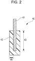
- FIG. 1A to FIG. 1C each represent a cross-sectional view of an example of the electro-conductive roller.
- An electro-conductive roller 10 illustrated in FIG. 1A has an electro-conductive base 12 and an elastic layer 13 provided on the periphery of the electro-conductive base 12, in which an electro-conductive resin layer 14 is formed on the periphery of the elastic layer 13.
- the elastic layer 13 has a function of giving elasticity required for forming a nip of a predetermined width to the electro-conductive roller 10 in a contact portion of the electro-conductive roller 10 with other members, for example, an elecrophotographic photoconductor (hereinafter referred to as a photoconductor).
- the electro-conductive resin layer 14 contains the urethane resin having the specific structure described above.
- the electro-conductive roller 10 may have two or more of the elastic layers 13. As illustrated in FIG. 1B , the electro-conductive roller 10 may be one not having the elastic layer 13. However, it is suitable for the electro-conductive roller 10 to have the elastic layer 13 from the viewpoint of securing the nip. Furthermore, the electro-conductive roller 10 may have one or two or more electro-conductive resin layers as an intermediate layer 15 in addition to the electro-conductive resin layer 14 as illustrated in FIG. 1C . In this case, it is required for at least the electro-conductive resin layer of the outermost layer to contain the urethane resin having the specific structure described above.
- the base 12 has a solid or hollow cylindrical shape and functions as an electrode and a support member of the electro-conductive roller 10.
- the base 12 contains metals, such as aluminum and copper; alloys, such as stainless steel; iron subjected to plating treatment with chromium or nickel; and conductive materials, such as synthetic resin having electro-conductivity.
- the elastic layer 13 is suitably a molded body of rubber materials.
- the rubber materials the following substances are mentioned, for example. Mentioned are an ethylene-propylene-diene copolymer rubber (EPDM), an acryl nitrile-butadiene rubber (NBR), a chloroprene rubber (CR), a natural rubber (NR), an isoprene rubber (IR), a styrenebutadiene rubber (SBR), a fluororubber, a silicone rubber, an epichlorohydrin rubber, an NBR hydride, and a urethane rubber. These rubber materials can be used alone or in combination of two or more kinds thereof.
- EPDM ethylene-propylene-diene copolymer rubber
- NBR acryl nitrile-butadiene rubber
- CR chloroprene rubber
- NR natural rubber
- IR isoprene rubber
- SBR styrenebutadiene rubber
- fluororubber
- the silicone rubber is particularly suitable from the viewpoint of the prevention of permanent deformation due to compression and flexibility.
- the silicone rubber include polydimethylsiloxane, polytrifluoropropylsiloxane, polymethylvinylsiloxane, polyphenylvinylsiloxane, and copolymers of the polysiloxanes.
- additives such as an electro-conductivity imparting agent, a non-conductive filler, a crosslinking agent, and a catalyst, are compounded as appropriate in the range where the purposes of compounding these additives are achieved and the effects disclosed herein are not impaired.
- the electro-conductivity imparting agent carbon black; electro-conductive metals, such as aluminum and copper; fine particles of electro-conductive metal oxides, such as zinc oxide, tin oxide, and titanium oxide; and ion conductive agents, such as quaternary ammonium salt, can be used.
- the carbon black is particularly suitable from the viewpoint of relatively easy availability and the viewpoint of electro-conductivity imparting performance and reinforcement performance.
- non-conductive filler examples include silica, quartz powder, titanium oxide, zinc oxide, or calcium carbonate.
- the crosslinking agent is not particularly limited, and tetraethoxysilane, di-t-butylperoxide, 2,5-dimethyl-2,5-di(t-butylperoxy)hexane, or dicumyl peroxide are mentioned, for example.
- the thickness of the elastic layer 13 is suitably 0.3 mm or more and 4.0 mm or less.
- the electro-conductive resin layer 14 of the outermost layer has the structure of the silicone graft fluororesin and the structure represented by Formula (1) shown below,
- A1 represents at least one structure selected from (A101) to (A104) shown below.
- (A101) is a structure containing a structure represented by Formula (A101a) shown below and a structure represented by either or both of Formula (A101b) and Formula (A101c) shown below,
- (A102) is a structure containing a constituent unit represented by Formula (A102a) shown below and a constituent unit represented by either or both of Formula (A102b) and Formula (A102c) shown below,
- R1 and R2 each independently represent a hydrogen atom or an alkyl group having carbon atoms of 1 or more and 4 or less and it is suitable that R1 and R2 in Formula (A102a) to Formula (A102c) each independently represent a hydrogen atom or a methyl group.
- (A103) is a structure represented by Formula (A103a) shown below,
- R3 and R4 each independently represent a hydrogen atom or an alkyl group having carbon atoms of 1 or more and 4 or less and m represents an integer of 7 or more, R3 and R4 are suitably hydrogen atoms or methyl groups, and m is an integer of 9 or more and 12 or less.
- (A104) is a structure represented by Formula (A104a) shown below,
- R5 and R6 each independently represent a hydrogen atom or an alkyl group having carbon atoms of 1 or more and 4 or less and p represents an integer of 6 or more, it is suitable that R5 and R6 each independently represent a hydrogen atom or a methyl group, and p is an integer of 7 or more and 12 or less.
- All the structures of (A101) to (A104) have relatively low crystallinity and have low polarity due to a structure in which the carbon atoms are continuously bonded to some extent. Therefore, it is considered that the structures prevent the aggregation of the siloxane structures in the urethane resin.
- the structures of (A101) and (A102) have a structure in which four or more carbon atoms are connected, and therefore the polarity is low and the polarity difference generated between the structure and the silicone graft fluororesin frame can be reduced. Moreover, a side chain is introduced into the main chain of the structure and the crystallinity is also kept low. For example, it is proved that the crystallinity of one having the structure represented by either or both of Formula (A101b) and Formula (A101c) is lower than the crystallinity of a polytetramethylene structure in which only the structures represented by Formula (A101a) are connected.
- the structures of (A103) and (A104) have a structure in which 7 or more carbon atoms and 6 or more carbon atoms are connected, and therefore the polarity is kept low.
- the structures of (A103) and (A104) initially have low crystallinity, and therefore it is not always needed to introduce a side chain thereinto to reduce the crystallinity as in the structures of (A101) and (A102).
- the structure of A1 in Formula (1) it is suitable for the structure of A1 in Formula (1) to have at least one structure selected from (A101) to (A103) among the structures of (A101) to (A104).
- the structure of A1 has at least one structure selected from (A101) to (A103)
- plastic deformation of the member for electrophotography is more difficult to occur.
- the urethane resin is suitably one having constituent units represented by Formula (2) and Formula (3) shown below,
- R7 represents any one selected from the group consisting of a hydrogen atom, a halogen atom, an alkyl group having carbon atoms of 1 or more and 10 or less, and a substituted or unsubstituted aryl group having carbon atoms of 6 or more and 10 or less
- R8 and R9 each independently represent any one selected from the group consisting of a hydrogen atom, a halogen atom, an alkyl group having carbon atoms of 1 or more and 10 or less, and a substituted or unsubstituted aryl group having carbon atoms of 6 or more and 10 or less.
- R7 represents a fluorine atom and R8 and R9 each independently represent any one selected from the group consisting of a hydrogen atom, a fluorine atom, and a chlorine atom.
- R7 to R9 may vary in each constituent unit.
- R10 represents any one selected from the group consisting of a hydrogen atom, a halogen atom, an alkyl group having carbon atoms of 1 or more and 10 or less, a substituted or unsubstituted aryl group having carbon atoms of 6 or more and 10 or less
- L represents a linking group
- R11 to R15 each independently represent a hydrogen atom or an alkyl group having carbon atoms of 1 or more and 2 or less
- R16 to R17 each independently represent any one selected from the group consisting of a hydrogen atom, a halogen atom, an alkyl group having carbon atoms of 1 or more and 10 or less, and a substituted or unsubstituted aryl group having carbon atoms of 6 or more and 10 or less
- n represents an integer of 1 or more.
- the linking group L in Formula (3) is a bond formed by a known reaction of introducing the siloxane structure portion in Formula (3) into a side chain and is not particularly limited.
- Specific examples of the linking group L include a single bond, a straight or branched-chain alkylene group having carbon atoms of 1 or more and 2 or less, or a group in which an arbitrary carbon-carbon bond in the alkylene group is substituted by an ester bond, an ether bond, an amide bond, or a combination thereof.
- the number of the carbon numbers in the alkylene group is not particularly limited and is suitably 2 or more and 10 or less.
- R10 is suitably a hydrogen atom, a fluorine atom, or an alkyl group having carbon atoms of 1 or more and 2 or less
- R11 to R14 are suitably an alkyl group having carbon atoms of 1 or more and 2 or less
- R15 is suitably an alkyl group having carbon atoms of 1 or more and 2 or less
- R16 and R17 are suitably a hydrogen atom or a methyl group.
- the urethane resin may have a constituent unit represented by Formula (4) shown below in addition to the constituent units represented by Formula (2) and Formula (3) .
- R18 in Formula (4) represents any one selected from the group consisting of a hydrogen atom, a halogen atom, an alkyl group having carbon atoms of 1 or more and 10 or less, and a substituted or unsubstituted aryl group having carbon atoms of 6 or more and 10 or less
- R19 represents any one selected from the group consisting of a single bond, an ether bond, and an ester bond
- R20 represents any one selected from the group consisting of an alkyl group having carbon atoms of 1 or more and 12 or less, a substituted or unsubstituted cycloalkylene group having carbon atoms of 6 or more and 10 or less, an alkenyl group having carbon atoms of 2 or more and 12 or less, and a substituted or unsubstituted aryl group having carbon atoms of 6 or more and 10 or less
- R21 and R22 each independently represent a hydrogen atom, a halogen atom, or an alkyl group having carbon
- the urethane resin having the structure represented by Formula (1) is suitably a cured product obtained by crosslinking a silicone graft fluororesin having a hydroxyl group (hereinafter referred to as a "hydroxyl group-containing silicone graft fluororesin") and polyol having the structures of (A101) to (A104) with an isocyanate compound.
- a silicone graft fluororesin having a hydroxyl group hereinafter referred to as a "hydroxyl group-containing silicone graft fluororesin”
- polyol having the structures of (A101) to (A104) with an isocyanate compound.
- the electro-conductive resin layer 14 can be formed by applying a coating solution obtained by mixing the components described above onto the elastic layer 13 or the base 12, followed by drying and curing by heating.
- a method for applying the coating solution is not particularly limited and spray coating, dip coating, or roll coating is mentioned.
- a dip coating method including causing a coating solution to overflow from the upper end of a dipping tank described in Japanese Patent Laid-Open No. 57-5047 is simple and excellent in production stability as a method for forming a resin layer.
- the thickness of the electro-conductive resin layer 14 is suitably 1.0 ⁇ m or more and 50 ⁇ m or less and particularly suitably 5 ⁇ m or more and 30 ⁇ m or less.
- the hydroxyl group-containing silicone graft fluororesin reacts with an isocyanate group in an isocyanate compound described later.
- the hydroxyl group-containing silicone graft fluororesin is suitably one having the constituent units represented by Formula (2) and Formula (3) shown above and Formula (5) shown below,
- R23 represents any one selected from the group consisting of a hydrogen atom, a halogen atom, a substituted or an unsubstituted alkyl group having carbon atoms of 1 or more and 10 or less, and a substituted or unsubstituted aryl group having carbon atoms of 6 or more and 10 or less.
- R24 represents any one selected from the group consisting of a single bond, an ether bond, and an ester bond.
- R25 represents any one selected from the group consisting of an alkylene group having carbon atoms of 1 or more and 10 or less, a substituted or unsubstituted cycloalkylene group having carbon atoms of 6 or more and 10 or less, an alkenylene group having carbon atoms of 2 or more and 10 or less, and a substituted or unsubstituted arylene group having carbon atoms of 6 or more and 10 or less.
- R26 and R27 each independently represent any one selected from the group consisting of a hydrogen atom, a halogen atom, and an alkyl group having carbon atoms of 1 or more and 5 or less.
- specific examples of the substituents include an alkyl group having C1 to C4, such as methyl group, ethyl group, n-propyl group and n-butyl group.
- the molecular weight of the hydroxyl group-containing silicone graft fluororesin is not particularly limited and the number average molecular weight thereof is suitably 5000 or more and 2500000 or less and particularly suitably 20000 or more and 100000 or less. When the number average molecular weight is in the ranges mentioned above, the toner adhesion prevention effect is high and gelling is hard to occur in a reaction.
- the molecular weight (number average molecular weight) of the constituent unit portion represented by Formula (3) in the hydroxyl group-containing silicone graft fluororesin is 200 or more and 100000 or less, particularly suitably 1000 or more and 50000 or less, and still more suitably 15000 or more and 30000 or less. When the molecular weight is in the ranges mentioned above, the toner adhesion prevention effect is higher.
- commercially-available items can be used as the hydroxyl group-containing silicone graft fluororesin.
- Examples of the commercially-available items include "ZX001”, “ZX007C”, “ZX017”, “ZX022”, “ZX022C”, and “ZX022H” (all Trade Names, manufactured by T&K TOKA Co, Ltd.), for example.
- the hydroxyl group-containing silicone graft fluororesin can be obtained by the following two methods (i) and (ii).
- the hydroxyl group-containing silicone graft fluororesin can be obtained by polymerizing a fluorine-containing polymerizable compound giving the constituent unit represented by Formula (2), a polymerizable compound having a siloxane structure giving the constituent unit represented by Formula (3), and a polymerizable compound having a hydroxyl group giving the constituent unit represented by Formula (5).
- the fluorine-containing polymerizable compound is suitably chlorotrifluoroethylene, tetrafluoroethylene, or ⁇ , ⁇ , ⁇ -trifluorostyrene.
- Examples of the polymerizable compound having a siloxane structure include a polymerizable compound having a radical polymerizable group.
- Specific examples of the radical polymerizable group include a vinyl group, an allyl group, and a (meth)acryloyl group.
- the polymerizable compound having a siloxane structure in the side chain the following substances are specifically suitable; vinyl-modified organodisiloxane, such as vinyl(trimethylsiloxy)dimethylsilane; (meth)acryl-modified organodisiloxane, such as (meth)acryloyloxy (trimethylsiloxy)dimethylsilane; trifluorovinyl-modified organodisiloxane, such as 5,6,6-trifluoro-5-hexenyl(triethylsiloxy)diethyl silane; one-terminal vinyl-modified dimethyl polysiloxane; one-terminal (meth)acryl-modified dimethyl polysiloxane; and one-terminal trifluorovinyl-modified dimethyl polysiloxane.
- vinyl-modified organodisiloxane such as vinyl(trimethylsiloxy)dimethylsilane
- the number average molecular weight of the polymerizable compounds having a siloxane structure is not particularly limited and is suitably 1000 or more and 50000 or less and particularly 10000 or more and 30000 or less.
- the polymerizable compounds having a siloxane structure can be prepared by a known method.
- the trifluorovinyl-modified organodisiloxane can be obtained by causing halosilane to react with a polymerizable compound having a trifluorovinyl group.
- the one-terminal-modified dimethyl polysiloxanes can be prepared by a combination of a cleavage reaction by organic lithium of cyclic siloxane and a reaction with halosilane having a radical polymerizable group, such as a chlorovinylsilane.
- commercially-available items can also be used as the polymerizable compounds having a siloxane structure in the side chain.
- examples of the commercially-available items of the one-terminal-modified dimethyl polysiloxane include "SILAPLANE FM-0711”and “SILAPLANE FM-0725” (all Trade Names, manufactured by JNC) and "X22-174DX” (manufactured by Shin-Etsu Chemical Co., Ltd.).
- the polymerizable compounds having a siloxane structure can be used alone or as a mixture of two or more kinds thereof.
- hydroxyl group-containing (meth)acrylates such as hydroxymethyl (meth)acrylate, 2-hydroxyethyl (meth)acrylate, 2-hydroxypropyl acrylate, 3-hydroxypropyl (meth)acrylate, 4-hydroxybutyl (meth)acrylate, 3-hydroxybutyl (meth)acrylate, 6-hydroxyhexyl (meth)acrylate, 8-hydroxyoctyl (meth)acrylate, ethyl 2-(hydroxymethyl) (meth)acrylate, 2-hydroxy-3-phenoxypropyl (meth)acrylate, and 1,4-cyclohexane dimethanol mono(meth)acrylate; and hydroxyl group-containing vinylethers, such as 2-hydroxyethylvinylether, 3-hydroxypropylvinylether, 4-hydroxybutylvinylether, 6-hydroxyhexylvinylether, diethylene glycol monovinylether, and 2-ethyl group-containing (meth)acrylates), such as 2-hydroxymethyl (meth)acryl
- (meth)acrylate When the " (meth)acrylate” is referred to, acrylates and/or methacrylates are referred to.
- the polymerizable compounds having a hydroxyl group can be used alone or as a mixture of two or more kinds thereof.
- the hydroxyl group-containing silicone graft fluororesin may be obtained by polymerizing a polymerizable compound giving the constituent unit represented by Formula (4) shown above in combination with the polymerizable compounds described above.
- polymerizable compounds are the following substances; (meth)acrylates, such as ethyl (meth)acrylate, t-butyl (meth)acrylate, isobutyl (meth)acrylate, n-butyl (meth)acrylate, n-hexyl methacrylate, n-octyl (meth)acrylate, n-lauryl (meth)acrylate, 2-ethylhexyl (meth)acrylate, and cyclohexyl (meth)acrylate; and vinyl ethers, such as methylvinylether, ethylvinylether, t-butylvinylether, isobutylvinylether, n-butylvinylether, n-
- polymerization reaction known arbitrary polymerization reaction methods can be used.
- a solution radical polymerization method or a nonaqueous dispersion radical polymerization method is suitably used.
- photoradical initiators and thermal radical initiators can be used.
- the photoradical initiators include acetophenones, benzoins, benzophenones, phosphine oxides, ketals, anthraquinones, thioxanthones, azo compounds, peroxides, 2,3-dialkyldione compounds, disulfide compounds, fluoroamine compounds, aromatic sulfoniums, lophine dimers, onium salts, borate salts, active esters, active halogens, inorganic complexes, and coumarins. These initiators may be used alone or as a mixture.
- the photoradical initiators are suitably used in the range of 0.1 part by mass or more and 15 parts by mass or less based on 100 parts by mass of monomers. Moreover, photosensitization agents, such as n-butylamine and triethylamine, may be added as necessary. As the thermal radical initiators, organic or inorganic peroxides and organic azo and diazo compounds can be used.
- the urethane resin obtained by the polymerization reaction of (i) described above has the constituent unit represented by Formula (2) shown above and the constituent unit represented by Formula (3) shown above in the same chain. Specifically, the urethane resin has a structure represented by Formula (6) shown below,
- A2 is a structure containing the constituent unit represented by Formula (2) shown above and the constituent unit represented by Formula (3) shown above.
- the hydroxyl group-containing silicone graft fluororesin can be obtained by using a solvent soluble fluororesin having a radical polymerizable group in place of the fluorine-containing polymerizable compound in the polymerization reaction of (i) described above.
- the solvent soluble fluororesin having a radical polymerizable group can be obtained by introducing a radical polymerizable group into a solvent soluble fluororesin.
- the solvent soluble fluororesin is a fluororesin which dissolves in an organic solvent and has advantages in that the solvent soluble fluororesin can react in an organic solvent and is easily dissolved in an organic solvent to be formed into a coating solution.
- the solvent soluble fluororesin can be obtained by causing a fluorine-containing polymerizable compound and other polymerizable compounds or polymerizable compounds having a hydroxyl group to react with each other in the same manner as in the method (i) described above.
- solvent soluble fluororesin examples include, for example, "Cefral Coat” series (PX-40, A202B, A606X, and CF803, all Trade Names, manufactured by Central Glass Co., Ltd.), "LUMIFLON” series (LF-100, LF-200, LF-302, LF-400, LF-554, LF-600, and LF-986N, all Trade Names, manufactured by Asahi Glass Co., Ltd.), "ZAFLON” series (FC-110, FC-220, FC-250, FC-275, FC-310, FC-575, and XFC-973, all Trade Names, manufactured by Toagosei Co., Ltd.), "ZEFFLE GK-510" (Trade Name, manufactured by Daikin Industries, LTD.), and “FLUONATE” series (Trade Name, manufactured by Dainippon Ink and Chemicals, Incorporated).
- the solvent soluble fluororesins having a hydroxyl group can be used alone or as a mixture of two or more kinds thereof.
- the solvent soluble fluororesin has a hydroxyl group in the molecule. Therefore, a radical polymerizable group can be introduced into the molecule by causing a polymerizable compound having both an organic group capable of reacting with such a hydroxyl group and a radical polymerizable group to react therewith.
- the organic group capable of reacting with a hydroxyl group include an isocyanate group, a carboxyl group, a hydroxyl group, an aldehyde group, and an epoxy group, for example.
- the isocyanate group is suitable because the isocyanate group has high reactivity and easily reacts.
- the radical polymerizable group include a vinyl group, an allyl group, and a (meth)acryloyl group, for example.
- polymerizable compound having both an organic group capable of reacting with a hydroxyl group and a radical polymerizable group examples include methacryloyl isocyanate, 2-isocyanatoethyl methacrylate, allyl isocyanate, m-, or p-isopropenyl- ⁇ , ⁇ -dimethylbenzyl isocyanate, for example. These compounds can be used alone or as a mixture of two or more kinds thereof.
- the constituent unit represented by Formula (3) shown above is present in a branched chain branched from the fluororesin frame of the structure of the silicone graft fluororesin, unlike the method (i) described above.
- polyol those having at least one structure selected from (A101) to (A104) shown above are used.
- Polyol having the (A101) structure is suitably polyether polyol having the specific structure described above and particularly suitably polyether diol obtained by performing ring opening copolymerization of tetrahydrofuran and 3-methyl-tetrahydrofuran.
- the number average molecular weight of the polyol having the (A101) structure is suitably 500 or more and 5000 or less and particularly suitably 1000 or more and 3000 or less.
- Examples of the polyol having the (A101) structure include "PTG-L1000" and "PTG-L3000” manufactured by HODOGAYA CHEMICAL CO., LTD.
- Polyol having the (A102) structure is suitably polybutadiene diol or polyisoprene diol.
- the number average molecular weight of the polyol having the (A102) structure is suitably 1000 or more and 5000 or less and particularly suitably 1000 or more and 4000 or less.
- Examples of the polyol having the (A102) structure include "Poly ip” and “Poly bd” manufactured by Idemitsu Kosan and "G-1000", “G-2000”, and “G-3000” manufactured by Nippon Soda Co., Ltd.
- Polyol having the (A103) structure is suitably polycarbonate diol derived from 1,9-nonanediol.
- the number average molecular weight of the polyol having the (A103) structure is suitably 500 or more and 5000 or less and particularly suitably 1000 or more and 3000 or less.
- Examples of the polyol having the (A103) structure include "Kuraray polyol C1090", “Kuraray polyol C2090", and "Kuraray polyol C3090" manufactured by Kuraray Co., Ltd.
- Polyol having the (A104) structure is suitably polyester diol derived from azelaic acid or sebacic acid.
- the number average molecular weight of the polyol having the (A104) structure is suitably 1000 or more and 5000 or less and particularly suitably 2000 or more and 4000 or less.
- Examples of the polyol having the (A104) structure include "URIC SE-2606" and "URIC SE-3506” manufactured by ITOH OIL CHEMICALS CO., LTD.
- polyol not having any structures of (A101) to (A104) may be used in combination as necessary insofar as the effects disclosed herein are not impaired.
- polyol the following substances are specifically mentioned; polyether polyols, such as polypropylene glycol, ethylene glycol, and tetraethyl glycol; and aliphatic polyester polyols obtained by a condensation reaction between diol components, such as 1,4-butanediol, 3-methyl-1.5-pentanediol, and neopentyl glycol or triol components, such as trimethylolpropane, and dicarboxylic acids, such as glutaric acid, adipic acid, and sebacic acid.
- diol components such as 1,4-butanediol, 3-methyl-1.5-pentanediol, and neopentyl glycol or triol components, such as trimethylolpropane, and dicarboxylic acids, such as gluta
- the polyols not having any structures of (A101) to (A104) may be prepolymers subjected to chain extension beforehand as necessary with isocyanates, such as 2,4-tolylene diisocyanate (TDI), 1,4 diphenylmethane diisocyanate (MDI), and isophorone diisocyanate (IPDI). Further, as the polyol, polyol having at least one structure selected from (A101) to (A104) and the prepolymers may be used in combination.
- isocyanates such as 2,4-tolylene diisocyanate (TDI), 1,4 diphenylmethane diisocyanate (MDI), and isophorone diisocyanate (IPDI).
- TDI 2,4-tolylene diisocyanate
- MDI 1,4 diphenylmethane diisocyanate
- IPDI isophorone diisocyanate
- the isocyanate compound reacts with the hydroxyl group in the hydroxyl group-containing silicone graft fluororesin and the polyol having the specific structure described above to form a urethane bond, and then crosslinks the same.
- the isocyanate compound known diisocyanates having two or more isocyanate groups can be suitably used and the isocyanate compound is not particularly limited. Specifically, the following substances are suitably used; aliphatic polyisocyanates, such as ethylene diisocyanate and 1,6-hexamethylene diisocyanate (HDI); alicyclic polyisocyanates, such as isophorone diisocyanate (IPDI), cyclohexane 1,3-diisocyanate, and cyclohexane 1,4-diisocyanate; and aromatic isocyanates, such as 2,4-tolylene diisocyanate, 2,6-tolylene diisocyanate (TDI), 4,4'-diphenylmethane diisocyanate (MDI), polymeric diphenylmethane diisocyanate, xylylene diisocyanate, and naphthalene diisocyanate.
- aliphatic polyisocyanates such as
- the isocyanate compounds may also be formed into prepolymers subjected to chain extension with polyols beforehand.
- the isocyanate content in the prepolymers is suitably in the range of 3.0% by mass or more and 5.0% by mass or less.
- the isocyanate compound is suitably mixed in such a manner that the ratio of the number of the isocyanate groups to the total of the number of the hydroxyl groups of the hydroxyl group-containing silicone graft fluororesin and the number of the hydroxyl groups of the polyol (hereinafter referred to as "NCO group/OH group ratio”) is in the range of 1.0 or more and 2.0 or less.
- FIG. 5 shows the structural formula of a part of the structure of an example of urethane resin.
- the urethane resin is obtained by cross-linking the hydroxyl group-containing silicone graft fluororesin and the polyols having the structures represented by Formula (A102a) and Formula (A102c) with polymeric MDI.
- the urethane resin has the constituent units represented by Formula (2) and Formula (3).
- the portion corresponding to A1 in Formula (1) has the structures represented by Formula (A102a) and Formula (A102c) and is sandwiched between the adjacent urethane bonds.
- e, f, h, and k each independently represent a positive integer.
- a filler a conducting agent, a softener, a processing aid, an adhesion imparting agent, a surface tack eliminator, and a foaming agent, which are generally used as compounding agents of resin, can be added insofar as the purposes of compounding the compounding agents are achieved and the effects disclosed herein are not impaired.
- carbon black As the conducting agent, carbon black; electro-conductive metals, such as aluminum and copper; fine particles of electro-conductive metal oxides, such as zinc oxide, tin oxide, and titanium oxide; ion conductive agents, such as quaternary ammonium salt, borate salt, perchlorate, and ionic liquid, can be used.
- electro-conductive metals such as aluminum and copper
- fine particles of electro-conductive metal oxides such as zinc oxide, tin oxide, and titanium oxide
- ion conductive agents such as quaternary ammonium salt, borate salt, perchlorate, and ionic liquid
- the carbon black and the ion conductive agents are particularly suitable because the carbon black and the ion conductive agents can prevent resistance changes when printing in large quantities is repeatedly performed in a high temperature and high humidity environment.
- the content of the carbon black is suitably 10 parts by mass or more and 30 parts by mass or less based on 100 parts by mass of the solid content of resin forming the electro-conductive resin layer 14 from the viewpoint of hardness, dispersibility, and electro-conductivity.
- the content of the ion conductive agent is suitably 0.1 part by mass or more and 10 parts by mass or less based on 100 parts by mass of the resin solid content from the viewpoint of bleed out and electro-conductivity.
- additives such as a non-conductive filler, a crosslinking agent, and a catalyst, can be compounded as appropriate insofar as the purposes of compounding the compounding agents are achieved and the effects disclosed herein are not impaired as in the elastic layer 13 described above.
- these additives the same additives mentioned as the additives for the elastic layers 13 can also be used.
- roughness controlling fine particles may be added to the electro-conductive resin layer 14.
- the volume average particle diameter of the roughness controlling fine particles is suitably 3 ⁇ m or more and 20 ⁇ m or less.
- the addition amount of the roughness controlling fine particles to be added to the electro-conductive resin layer 14 is suitably 1 part by mass or more and 50 parts by mass or less based on 100 parts by mass of the resin solid content of the electro-conductive resin layer 14.
- fine particles of polyurethane resin, polyester resin, polyether resin, polyamide resin, acrylic resin, and phenol resin can be used.
- the intermediate layer 15 is an electro-conductive resin layer.
- a binder resin forming the intermediate layer 15 known resin can be used and the binder resin is not particularly limited.
- the binder resin the following substances are mentioned, for example and these substances may be used alone or in combination of two or more kinds thereof. Mentioned are urethane resin, epoxy resin, urea resin, ester resin, amide resin, imide resin, amide imide resin, phenol resin, vinyl resin, silicone resin, and fluororesin.
- the urethane resin is particularly suitable from the viewpoint of wear resistance and flexibility.
- An electro-conductive blade is mentioned as an example of a member for electrophotography.
- FIG. 2 is a cross-sectional view along the direction orthogonal to the longitudinal direction of an example of an electro-conductive blade.
- An electro-conductive blade 40 contains an electro-conductive support base material (base) 41 and an electro-conductive resin layer 42 provided on the periphery of the electro-conductive support base material 41.
- the support base material 41 has a blade shape and functions as an electrode and a support member of the electro-conductive blade.
- the support base material 41 contains metals, such as aluminum and copper; alloys, such as stainless steel, iron subjected to plating treatment with chromium or nickel, and conductive materials, such as synthetic resin having electro-conductivity.
- the electro-conductive resin layer 42 is the same as the electro-conductive resin layer 14 of the first embodiment.
- the electro-conductive resin layer 42 can be formed by applying a coating solution produced in the same manner as in the formation method of the electro-conductive resin layer 14 by spray coating or dip coating, drying the same, and then curing a coating film by heating.
- the thickness of the electro-conductive resin layer 42 is suitably 1.0 ⁇ m or more and 50 ⁇ m or less and particularly suitably 5 ⁇ m or more and 30 ⁇ m or less.
- the member for electrophotography described above can be suitably used as an electro-conductive roller, such as a developing roller, a transfer roller, a charging roller, and a developer supplying roller, and an electro-conductive blade, such as a cleaning blade and a developing blade, of an electrophotographic apparatus.
- an electro-conductive roller such as a developing roller, a transfer roller, a charging roller, and a developer supplying roller
- an electro-conductive blade such as a cleaning blade and a developing blade
- the member for electrophotography can be suitably used as a developing roller, a charging roller, or a developing blade.
- FIG. 3 is a cross-sectional view of an example of an electrophotographic apparatus and has the member for electrophotography described above as a developing roller.
- a developing apparatus 22 containing a developing roller 11 (electro-conductive roller), a toner supplying roller 19, a toner container 20, and a developing blade 21 is detachably attached.
- the developing roller 11 is located in an opening portion extending in the longitudinal direction in the toner container 20 and is disposed facing a photoconductor 18.
- the toner container 20 accommodates a toner 20a as a one-component developer.
- the toner 20a is supplied to the surface of the developing roller 11 by the toner supplying roller 19, and then a toner layer having a predetermined thickness is formed on the surface of the developing roller 11 with the developing blade 21.
- a process cartridge 17 shown in Fig. 4 which contains a photoconductor 18, a cleaning blade 26, a waste toner accommodating container 25, and a charging roller 24 is detachably attached to the electrophotographic apparatus.
- the photoconductor 18, the cleaning blade 26, the waste toner accommodating container 25, and the charging roller 24 may be disposed in the main body of the electrophotographic apparatus.
- the photoconductor 18 rotates in the direction indicated by the arrow in FIG. 3 and is uniformly charged by the charging roller 24, so that an electrostatic latent image is formed on the surface of the photoconductor 18 by laser light 23.
- the electrostatic latent image is developed by the toner 20a given by the developing apparatus 22 disposed in contact with the photoconductor 18 to be visualized as a toner image.
- a development method is so-called reversal development, by which a toner image is formed in an exposure portion.
- the toner image on the photoconductor 18 is transferred to paper 34 which is a recording medium with the transfer roller 29 which is a transfer member.
- the paper 34 is fed onto an endless belt-shaped transfer conveying belt 32 through a paper feeding roller 35 and an absorbing roller 36.
- the paper 34 is conveyed between the photoconductor 18 and the transfer roller 29 by the transfer conveying belt 32.
- the transfer conveying belt 32 works by a driven roller 33, a driving roller 28, and a tension roller 31.
- a voltage is applied to the transfer roller 29 and the absorbing roller 36 from a bias power supply 30.
- the paper 34 to which the toner image is transferred is subjected to fixing treatment by a fixing apparatus 27, and then discharged to the outside of the apparatus to complete the print operation.
- the cleaning blade 26 which is a cleaning member for cleaning the surface of the photoconductor 18, and then accommodated in the waste toner accommodating container 25.
- the cleaned photoconductor 18 repeatedly performs the above-described action.
- FIG. 4 is a cross-sectional view of an example of a process cartridge.
- the process cartridge 17 is configured so that the developing apparatus 22, the photoconductor 18, the cleaning blade 26, the waste toner accommodating container 25, and the charging roller 24 are integrated and configured so as to be detachably attached to the main body of the electrophotographic image forming apparatus.
- the developing apparatus 22 contains the developing roller 11, the developing blade 21, the toner supplying roller 19, and the toner container 20 and has the electro-conductive roller described above as the developing roller 11.
- the toner container 20 in the developing apparatus 22 is filled with the toner 20a.
- the developing apparatus 22 may be detachable and attachable.
- One aspect of the present disclosure can provide a member for electrophotography which has toner filming resistance and is difficult to cause plastic deformation, even when a load is applied thereto over a long period of time in a high temperature and high humidity environment.
- Another aspect of the present disclosure can provide a process cartridge and an electrophotographic apparatus capable of stably forming a high grade electrophotographic image even in a high temperature and high humidity environment.
- a polymerizable compound having a siloxane structure in the side chain was synthesized.
- 0.5 g of trimethyl silanol (manufactured by Tokyo Kasei Kogyo Co., Ltd.) was poured into a glass reactor having a mechanical stirring device and a dropping funnel, and then stirred in an ice bath.
- 3.6 ml of a hexane solution of n-butyl lithium (1.6 mol/L) (manufactured by Tokyo Kasei Kogyo Co., Ltd.) was added dropwise.
- the resultant mixture was stirred in an ice bath for 1 hour, and then a solution in which 24.66 g of hexamethylcyclotrisiloxane (manufactured by Tokyo Kasei Kogyo Co., Ltd.) was dissolved in 25 g of THF was gradually added dropwise.
- the ice bath was removed, the resultant mixture was stirred for 6 hours, 1.0 g of chlorodimethylvinylsilane (manufactured by Tokyo Kasei Kogyo Co., Ltd.) was added dropwise to the resultant mixture, and then the resultant mixture was further stirred for 12 hours.
- the number average molecular weight (Mn) of the obtained terminal vinyl-modified dimethylpolysiloxane S-1 was measured by the following measuring apparatus under the following measurement conditions.
- the measurement sample 0.1% by mass of a toluene solution was used. Furthermore, the measurement was performed using an RI (refractive index) detector as a detector.
- the calibration curve was created using TSK standard polystyrene (Trade Names "A-1000”, “A-2500”, “A-5000”, “F-1", “F-2”, “F-4”, “F-10”, “F-20”, “F-40”, “F-80”, and “F-128", manufactured by TOSOH CORP.) as reference samples for creating the calibration curve. Based on the calibration curve, the number average molecular weight was determined from the retention time of the obtained measurement sample.
- the number average molecular weight of the terminal vinyl-modified dimethylpolysiloxane S-1 was 15000.
- L-1 has the constituent unit represented by Formula (3) in the branched chain branched from the main chain of the fluororesin frame.
- the number average molecular weight (Mn) of the obtained hydroxyl group-containing silicone graft fluororesin L-1 was measured by the following measuring apparatus under the following measurement conditions.
- the measurement sample 0.1% by mass of a THF solution was used. Furthermore, the measurement was performed using an RI (refractive index) detector as a detector.
- the calibration curve was created using TSK standard polystyrene (Trade Names "A-1000”, “A-2500”, “A-5000”, “F-1", “F-2”, “F-4”, “F-10”, “F-20”, “F-40”, “F-80”, and “F-128", manufactured by TOSOH CORP.) as reference samples for creating the calibration curve. Based on the calibration curve, the number average molecular weight was determined from the retention time of the obtained measurement sample.
- the number average molecular weight of the hydroxyl group-containing silicone graft fluororesin L-1 was 20000.
- Hydroxyl group-containing silicone graft fluororesins L-2 to L-4 were synthesized in the same manner as in L-1, except changing the compounding amount and the reaction time as shown in the following table 1.
- Terminal vinyl-modified dimethylpolysiloxane S-2 was synthesized in the same manner as in S-1, except changing the amount of the hexamethylcyclotrisiloxane (manufactured by Tokyo Kasei Kogyo Co., Ltd.) to 13.12 g and changing the stirring time after the completion of the dropwise addition to 4 hours.
- the number average molecular weight of the terminal vinyl-modified dimethylpolysiloxane S-2 was 8000.
- Hydroxyl group-containing silicone graft fluororesin L-5 was synthesized in the same manner as in L-1, except using the terminal vinyl-modified dimethylpolysiloxane S-2 and changing the compounding amount and the reaction time as shown in the following table 1.
- a soluble fluororesin F-2 having a methacryloyl group as a radical polymerizable group was synthesized in the same manner as in F-1, except using a solution in which 3.1 g (0.02 mol) of 2-isocyanateethyl methacrylate (manufactured by Tokyo Kasei Kogyo Co., Ltd.) was dissolved in 9.0 g of MEK in place of the MEK solution of allyl isocyanate.
- Hydroxyl group-containing silicone graft fluororesins L-6 to L-7 were synthesized in the same manner as in L-1, except using the soluble fluororesin F-2 and changing the compounding amount and the reaction time as shown in the following table 1.
- Table 1 Hydroxyl group-containing silicone graft fluororesin L-1 L-2 L-3 L-4 L-5 L-6 L-7
- Hydroxyl group-containing silicone graft fluororesin L-9 was synthesized in the same manner as in L-8, except using 8.7 g of the fluorine-containing polymerizable compound E-1 in place of the methacryl-modified dimethyl polysiloxane.
- the number average molecular weight of L-9 was measured in the same manner as in L-1, the number average molecular weight of L-9 was 30000.
- the polyol P-1 was synthesized as follows. In a glass reactor, a mixture of 461.4 g of dry tetrahydrofuran and 137.8 g of dry 3-methyltetrahydrofuran was held at a temperature of 10°C. Subsequently, 26.2 g of 70% perchloric acid and 240 g acetic anhydride were added, and then were caused to react with each other under stirring for 4 hours. The obtained reaction mixture was poured into 1000 g of a 20% sodium hydroxide aqueous solution. The pressure was further reduced to remove the remaining water and the solvent component to obtain a 498 g of liquid polyether diol P-1. When the number average molecular weight was measured in the same manner as in L-1, the number average molecular weight of P-1 was 5000.
- Isocyanate group terminal prepolymers B-2 to B-5 were synthesized in the same manner as in B-1, except changing the type and the compounding amount of polyols as shown in the following table 3.
- Table 3 Isocyanate group terminal prepolymer Polyol Compounding amount (g) Structure B-1 P-2 200.0 (A101) B-2 P-4 220.0 (A102) B-3 P-5 235.0 (A102) B-4 P-9 570.0 (A103) B-5 P-10 550.0 (A104)
- a primer (Trade Name "DY35-051", manufactured by Toray Industries Dow Corning) was applied to a stainless steel (SUS304) core metal with a diameter of 6 mm, and then baked for 20 minutes in an oven heated to a temperature of 180°C to be used as a base.
- Table 4 Material name Compounding amount Liquid silicone rubber material 100 parts by mass (Trade Name, SE6905A/B; manufactured by Toray Industries Dow Corning) Carbon black 15 parts by mass (Trade Name, TOKABLACK #4300; manufactured by Tokai Carbon Co., Ltd.)
- an electro-conductive resin layer As materials of an electro-conductive resin layer, 69.5 parts by mass of the polyol P-1, 53.5 parts by mass of the isocyanate group terminal prepolymer B-1, 1 part by mass of the hydroxyl group-containing silicone graft fluororesin L-1, 32.0 parts by mass of carbon black (Trade Name "MA230", manufactured by Mitsubishi Chemical Corporation), and 10.0 parts by mass of urethane resin particles (Trade Name, "Art Pearl C-800", manufactured by Negami Chemical Industrial CO., Ltd.) were stirred and mixed.
- methyl ethyl ketone was added so that the total solid content ratio was 30% by mass, and then mixed with a sand mill. Subsequently, further, the viscosity was adjusted to 10 to 12 cps with methyl ethyl ketone to prepare a coating solution for forming an electro-conductive resin layer.
- the elastic roller D-1 produced above was dipped in the coating solution to form a coating film of the coating solution on the surface of the elastic layer of the elastic roller D-1, and then dried. Furthermore, an electro-conductive resin layer with a film thickness of 15 ⁇ m was provided on the periphery of the elastic layer by heat-treating the same at a temperature of 150°C for 1 hour to produce a developing roller according to Example 1.
- the developing roller according to Example 1 thus obtained were evaluated for the following items.
- the evaluation results as a developing roller are shown in Table 6.
- a black toner cartridge for a laser beam printer (Trade Name "LBP7700C", manufactured by CANON KABUSHIKI KAISHA) having the configuration of FIG. 3 was prepared.
- a developing blade and the developing roller according to Example 1 were attached, and then the process cartridge was allowed to stand still for 60 days in an environment of a temperature of 40°C and a relative humidity of 95%RH (hereinafter referred to as a severe environment) in a state where the developing roller and the developing blade were in contact with each other.
- the contact pressure of the developing roller and the developing blade was adjusted to 0.6 N/cm on average, and the setting was changed to severer setting to plastic deformation.
- the process cartridge was allowed to stand still in an environment of a temperature of 23°C and a relative humidity of 55%RH for 6 hours, and then loaded into the laser beam printer. Then, halftone images were output, and then the halftone images were evaluated according to the following criteria.
- the evaluated developing roller was removed from the process cartridge, and then the amount of deformation ( ⁇ m) of the developing roller was measured as follows.
- the toner on the surface of the developing roller was removed by air blow, and then the base material of the developing roller was fixed in a state where the developing roller was rotatable.
- a laser displacement sensor (Trade Name "LT-9500V", manufactured by KEYENCE CORP.) was placed so that laser was vertically applied to the surface of the developing roller.
- the developing roller was rotated and driven at an arbitrary number of rotations, the maximum value and the minimum value of the displacement in the circumferential direction of the surface of the developing roller were read, and then a difference therebetween was determined.
- the measurement was performed at the center in the longitudinal direction of the developing roller and two points with a 43 mm pitch in the longitudinal direction from the center to both ends, i.e., five points in total, and then the average value of the values at the five points was determined as the amount of deformation.
- the evaluation of the toner stick density in the severe environment was performed by the following method.
- the developing roller according to Example 1 was attached to a yellow toner cartridge for a laser beam printer (Trade Name "LBP7700C", manufactured by CANON KABUSHIKI KAISHA) having the configuration of FIG. 3 .
- the yellow toner cartridge was loaded to the laser beam printer.
- an output operation of a white solid image image in which nothing was drawn on the sheet
- the developing roller in such a state was removed from the yellow toner cartridge.
- the developing roller was placed on a polytetrafluoroethylene flat plate, the developing roller was brought into pressure contact with the flat plate with a 2.94 N load (1.47 N load to each of both ends of the mandrel), and then the developing roller was allowed to stand for 60 days in the severe environment. Subsequently, the developing roller was released from the pressure contact state to the flat plate, the developing roller was allowed to stand still in an environment of a temperature of 25°C and a relative humidity of 45%RH for 3 hours, and then the surface of a developing roller was subjected to air blow.
- the toner sticking onto the developing roller was separated using an adhesive tape (Trade Name, "Mending tape”, manufactured by Sumitomo 3M Ltd.).
- the adhesive tape to which the yellow toner stuck was placed on a plain paper (Trade Name "office 70", manufactured by CANON KABUSHIKI KAISHA), and then the reflection density was measured using a reflection densitometer (Trade Name "TC-6 DS/A”, manufactured by Tokyo Denshoku. Co., Ltd.).
- an adhesive tape to which no toner stuck was similarly placed on a plain paper, and then the reflection density was similarly measured. Then, the density difference between the reflection density of the adhesive tape to which no toner stuck and the reflection density of the adhesive tape to which the yellow toner stuck was determined. Furthermore, the ratio of the density difference when the reflection density of the adhesive tape to which no toner stuck was set to 100 was determined to be used as the reflectance reduction amount (%). This measurement was performed at three points in total of a central part and both end portions of the developing roller, and then the arithmetic mean value was used as the toner stick density of the developing roller as the evaluation target.
- magenta toner cartridge for a laser beam printer (Trade Name "LBP7700C", manufactured by CANON KABUSHIKI KAISHA) having the configuration of FIG. 3 .
- the magenta toner cartridge was attached to the laser beam printer.
- the laser beam printer was allowed to stand in an environment of a temperature of 10°C and a relative humidity of 10%RH (hereinafter referred to as an L/L environment) for 24 hours, and then continuous printing was performed at a 0.5% printing rate. Images were checked at every 1000 sheets up to 20000 sheets. Then, it was confirmed whether a density difference between a printing portion and a non-printing portion due to filming was visually confirmed, and then the presence or absence of the generation of filming was evaluated.
- Developing rollers according to Examples 2 to 36 were produced in the same manner as in Example 1, except changing materials of the electro-conductive resin layer as shown in the following table 5. Then, the electro-conductive rollers according to Examples 2 to 36 were evaluated in the same manner as in Example 1. The evaluation results as a developing roller are shown in Table 6.
- Developing rollers according to Comparative Examples 1 to 6 were produced in the same manner as in Example 1, except changing materials of the electro-conductive resin layer as shown in the following table 5. Then, the electro-conductive rollers according to Comparative Examples 1 to 6 were evaluated in the same manner as in Example 1. The evaluation results as a developing roller are shown in Table 6.
- the amount of deformation after allowed to stand in the severe environment over a long period of time was small and the images were also good because the silicone graft fluororesin in the electro-conductive resin layer had the structure represented by Formula (1). Moreover, the toner stick in the severe environment was also prevented at a high level, and good filming resistance performance was shown even in the L/L environment.
- the developing rollers according to Examples 1 to 7, 9 to 10, and 13 to 36 in which the number average molecular weight of the silicone portion in the silicone graft fluororesin was 15000 or more exhibited a better toner stick value of 1.5% or less.
- the amount of deformation after allowed to stand in the severe environment over a long period of time was as small as less than 3 ⁇ m and the images were better.
- the developing rollers according to Comparative Examples 1 to 4 exhibited good filming resistance performance in the L/L environment.
- the urethane resin did not have the structure represented by Formula (1), the amount of plastic deformation after allowed to stand in the severe environment over a long period of time was large and the images were not good.
- the resin in the resin layer had the structure represented by Formula (1), and therefore a good set image with a small amount of deformation after allowed to stand in the severe environment over a long period of time was obtained.
- the resin did not have a side chain having the siloxane structure, the toner stick in the severe environment arose and the filming resistance was not good in the L/L environment.
- Silicone oil was added to the developing roller according to Comparative Example 6, and therefore, the toner stick was prevented and good filming resistance in the L/L environment was exhibited.
- rigid fluororesin was not contained in the resin layer, and therefore the amount of plastic deformation after allowed to stand in the severe environment over a long period of time was large.
- an unvulcanized elastic layer was provided on the mandrel with a crosshead extruder, and then heated in an oven heated to a temperature of 160°C for 70 minutes to cure the unvulcanized elastic layer. Thereafter, the surface of the elastic layer was ground with a rotary grinding wheel.
- an elastic roller D-2 was obtained in which the diameter of a central portion was 8.5 mm and the diameter at each position with a distance of 90 mm from the central portion toward both end portions was 8.4 mm.
- a charging roller according to Example 37 was produced in the same manner as in Example 1, except using the elastic roller D-2 and changing materials of the electro-conductive resin layer as shown in the following
- the charging roller according to Example 37 thus obtained was evaluated for the following items.
- the evaluation results as a charging roller are shown in Table 10.
- a black toner cartridge for a laser beam printer (Trade Name "HP LaserJet Enterprise Color CP4515dN", manufactured by HP) having the configuration of FIG. 3 was prepared.
- a charging roller attached to the laser beam printer was removed from the cartridge, and then the charging roller according to Example 37 was attached thereto.
- the cartridge was allowed to stand still for 60 days in the severe environment in a state where the charging roller and the photoconductor contacted each other.
- the pressing pressure by a spring was changed so that the contact pressure of the charging roller and the photoconductor was 5.0 N at one end, i.e., 10.0 N in total at both ends. Thereafter, the cartridge was allowed to stand still in the environment of a temperature of 23°C and a relative humidity of 55%RH for 6 hours.
- the resultant cartridge was loaded into the laser beam printer, halftone images were output, and then set mark images were evaluated according to the following criteria. Due to an increase in the resistance of the charging roller, uneven density in a thin streak shape arose in the halftone images in some cases. Such an image is referred to as a transverse streak in an image. The streak in an image tends to be more noticeable with an increase in the resistance due to sticking of toner and the like to the surface of the charging roller.
- the charging roller was removed from the evaluated process cartridge, and then the amount of deformation ( ⁇ m) of the radius of the charging roller was measured in the same manner as in the evaluation of the developing roller.
- a black toner cartridge for a laser beam printer (Trade Name "HP LaserJet Enterprise Color CP4515dN", manufactured by HP) having the configuration of FIG. 3 was prepared.
- a charging roller attached to the laser beam printer was removed from the cartridge, and then the charging roller according to Example 37 was attached thereto. Then, the cartridge was placed in the laser beam printer, and then allowed to stand in the L/L environment for 2 hours after the placement. Subsequently, a durability test of continuously outputting 4% black printing density images (images in which transverse lines with a width of 2 dots and an interval of 50 dots were drawn in a direction perpendicular to the rotation direction of a photoconductor) was performed.
- Halftone images (images in which transverse lines with a width of 1 dot and an interval of 2 dots were drawn in a direction perpendicular to the rotation direction of a photoconductor) were output in order to check the images after 100 images and 10000 images were output.
- the obtained images were visually observed, and then evaluated for the transverse streaks according to the following criteria. Images after 100 images were output were early images and images after 10000 images were output were images after durability.
- Charging rollers according to Examples 38 to 42 were produced in the same manner as in Example 37, except changing materials of the electro-conductive resin layer as shown in Table 9.
- the electro-conductive rollers according to Examples 38 to 42 were evaluated in the same manner as in Example 37.
- the evaluation results as a charging roller are shown in Table 10.
- Charging rollers according to Comparative Examples 7 to 9 were produced in the same manner as in Example 37, except changing materials of the electro-conductive resin layer as shown in Table 9.
- the electro-conductive rollers according to Comparative Examples 7 to 9 were evaluated in the same manner as in Example 37.
- the evaluation results as a charging roller are shown in Table 10.
- the amount of deformation after allowed to stand in the severe environment over a long period of time was small and the images were also good because the urethane resin in the electro-conductive resin layer had the structure represented by Formula (1). Moreover, the good images were maintained even after the charging rollers were subjected to the durability test in the L/L environment.
- the amount of deformation was as small as less than 5 ⁇ m after allowed to stand in the severe environment over a long period of time and images were also better.
- the charging rollers according to Comparative Examples 7 and 8 good images were maintained even after subjected to the durability test in the L/L environment.
- the urethane resin did not have the structure represented by Formula (1), and therefore the amount of deformation after allowed to stand in the severe environment over a long period of time was large and images were not good.
- the charging roller according to Comparative Example 9 did not contain rigid fluororesin in the resin layer, and therefore the amount of plastic deformation after allowed to stand in the severe environment over a long period of time was large and images were not good.
- a 0.08 mm thick SUS (stainless steel) sheet manufactured by Nisshin Steel Co., Ltd. was press-cut into a dimension of a length of 200 mm and a width of 23 mm.
- the cut SUS (stainless steel) sheet was dipped in the coating solution for forming an electro-conductive resin layer according to Example 37 so that a length 43 from a longitudinal end portion of the cut SUS sheet was 1.5 mm as illustrated in FIG. 2 to form a coating film of the coating solution, followed by drying.
- an electro-conductive resin layer 42 having a film thickness 44 of 10 ⁇ m was formed on the surface in the longitudinal end portion of the SUS sheet to produce a developing blade according to Example 43.
- the developing blade according to Example 43 thus obtained was evaluated for the following items.
- the developing blade according to Example 43 was evaluated for deformation recovery performance using an apparatus illustrated in FIG. 6 .
- the measuring apparatus has an LED dimension measuring device (Trade Name "LS-7000"; manufactured by KEYENCE CORP.) having a gripping portion (not illustrated) fixing the support base material 41 of the developing blade 40, a reference plate 51, an LED light emission portion 52, and a light receiving portion 53.
- LS-7000 LED dimension measuring device
- a distance 55 from an end portion on the side where the electro-conductive resin layer 42 was not formed of the support base material 41 of the developing blade 40 to the tip on the side of the electro-conductive resin layer 42 of the developing blade 40 was determined.
- the distance 55 was calculated by measuring a gap amount 54 between the tip of the developing blade 40 and the reference plate 51.
- the measurement of the gap amount 54 between the surface of the developing blade 40 and the reference plate 51 was performed at two points in total of positions with a distance of 20 mm from both end portions in the longitudinal direction of the developing blade 40 to the center side in the longitudinal direction.
- the measurement was performed in an environment of a temperature of 23°C and a relative humidity of 55%RH using a blade which was allowed to stand in an environment of a temperature of 23°C and a relative humidity of 55%RH for 6 hours or more.
- the developing blade 40 which was measured beforehand as described above was placed in a cyan cartridge for a laser beam printer (Trade Name "LBP7700C", manufactured by CANON KABUSHIKI KAISHA) so that the tip of the developing blade 40 contacted a developing roller.
- the developing roller was changed to a metal roller with a diameter of 12 mm and the contact pressure of the developing blade 40 was adjusted to 0.6 N/cm, so that the conditions were changed to conditions where deformation was more likely to occur than usual.
- the cartridge was allowed to stand for 30 days in the severe environment. Thereafter, the developing blade 40 was removed from the cartridge, and then allowed to stand in an environment of a temperature of 23°C and a relative humidity of 55%RH for 1 hour. Thereafter, the distance 55 from an end portion on the side of the support base material 41 of the developing blade 40 to the tip on the side of the electro-conductive resin layer 42 of the developing blade 40 was measured similarly to the measurement before contacting in an environment of a temperature of 23°C and a relative humidity of 55%RH. The measurement was performed at two places at the same positions as those of the measurement portions before allowed to stand in the severe environment.
- the amount of changes of the distance 55 from the end portion on the side of the support base material 41 of the developing blade 40 to the tip portion on the side of the electro-conductive resin layer 42 of the developing blade 40 before and after the contacting in a high temperature and high humidity environment at the contact position with a metal roller was determined.
- the average value of the amount of changes was defined as the amount of deformation [ ⁇ m].
- the image density difference of portions corresponding to a central portion and end portions in the longitudinal direction of the developing blade in the output image was measured as follows.
- the developing blade in which the evaluation of the above-described "Deformation recovery performance” was completed was placed in a cyan cartridge for a laser beam printer (Trade Name "LBP7700C", manufactured by CANON KABUSHIKI KAISHA).
- the cartridge was loaded into the laser beam printer, and then solid images were output.
- the density of the obtained solid images was measured, and then evaluated according to the following criteria.
- the time from the evaluation of deformation recovery performance to the output of the solid images was set to 1 hour.
- the image density was measured at arbitrary five points of portions corresponding to the central portion in the longitudinal direction and positions with a distance of 3 cm from the end portions to the central portion in the longitudinal direction of the developing blade using a reflection densitometer (Trade Name "GreatagMacbethRD918", manufactured by Macbeth). The average value was determined for each of the image density of the central portion and the image density of both end portions, and then the image density difference between the central portion and the end portions was determined. The image density difference was evaluated according to the following criteria.
- Sticking of toner to the developing blade may cause uneven density in a fine streak shape on an output image in a direction perpendicular to the rotation direction of a photoconductor.
- the image is referred to as a vertical streak in an image.
- the vertical streak in an image appears due to the fact that toner does not uniformly coat the developing roller owing to the generation of a stuck substance on the developing blade.
- a black toner cartridge for a laser beam printer (Trade Name "LBP7700C", manufactured by CANON KABUSHIKI KAISHA) having the configuration of FIG. 3 was prepared.
- a developing blade attached thereto was removed from the cartridge, the developing blade according to Example 43 was attached thereto, and then the cartridge was allowed to stand in the L/L environment for 2 hours after placed.
- a durability test of continuously outputting 1% black printing density images was performed. After 10000 images were output, a solid image was output in order to check the image. Then, the obtained images were visually observed, and then the presence or absence of the generation of vertical streaks was evaluated according to the following criteria.
- a developing blade according to Example 44 was produced in the same manner as in Example 43, except changing the coating solution for forming an electro-conductive resin layer to one prepared in Example 39. Moreover, a developing blade according to Example 45 was produced in the same manner as in Example 43, except changing the coating solution for forming an electro-conductive resin layer to one prepared in Example 41 and a developing blade according to Example 46 was produced in the same manner as in Example 43, except changing the coating solution to one prepared in Example 42.
- the developing blades according to Examples 44 to 46 were evaluated in the same manner as in Example 43. The evaluation results as a developing blade are shown in Table 11.
- Developing blades according to Comparative Examples 10 to 12 were produced in the same manner as in Example 43, except changing the coating solution for forming an electro-conductive resin layer to those prepared in Comparative Examples 7 to 9, respectively.
- the developing blades according to Comparative Examples 7 to 9 were evaluated in the same manner as in Example 43.
- the evaluation results as a developing blade are shown in Table 11.
- the urethane resin in the electro-conductive resin layer had the structure represented by Formula (1), and therefore the amount of deformation after allowed to stand in the severe environment over a long period of time was small and the image density difference was also small. Moreover, good images were obtained after the developing blades were subjected to the durability test in the L/L environment.
- the developing blades according to Comparative Examples 10 and 11 good images were maintained even after subjected to the durability test in the L/L environment.
- the urethane resin did not have the structure represented by Formula (1), and therefore the amount of plastic deformation after allowed to stand in the severe environment over a long period of time was large and images were not good.
- the developing blade according to Comparative Example 12 did not contain rigid fluororesin in the resin layer, and therefore the amount of plastic deformation after allowed to stand in the severe environment over a long period of time was large and image were not good.
Landscapes
- Physics & Mathematics (AREA)
- General Physics & Mathematics (AREA)
- Chemical & Material Sciences (AREA)
- Engineering & Computer Science (AREA)
- Chemical Kinetics & Catalysis (AREA)
- Medicinal Chemistry (AREA)
- Polymers & Plastics (AREA)
- Organic Chemistry (AREA)
- Health & Medical Sciences (AREA)
- Computer Vision & Pattern Recognition (AREA)
- Plasma & Fusion (AREA)
- Electrophotography Configuration And Component (AREA)
- Electrostatic Charge, Transfer And Separation In Electrography (AREA)
- Polyurethanes Or Polyureas (AREA)
- Rolls And Other Rotary Bodies (AREA)
- Dry Development In Electrophotography (AREA)
- Laminated Bodies (AREA)
Claims (10)
- Element für die Elektrophotographie, umfassend:eine elektrisch leitende Grundsubstanz (12); undmindestens eine elektrisch leitende Harzschicht (14), wobei die elektrisch leitende Harzschicht (14) einer äußersten Schicht Urethanharz enthält, unddas Urethanharz eine Struktur eines Silikonpfropf-Fluorharzes und eine durch die unten gezeigte Formel (1) dargestellte Struktur aufweist,
 wobei in Formel (1) A1 mindestens eine Struktur darstellt, die aus der unten gezeigten Gruppe bestehend aus (A101), (A102), (A103) und (A104) ausgewählt ist; wobei die (A101)-Struktur eine durch die unten gezeigte Formel (A101a) dargestellte Struktur und eine durch eine oder beide der unten gezeigten Formeln (A101b) und (A101c) dargestellte Struktur enthält;

 wobei die (A102)-Struktur eine konstituierende Einheit, die durch die unten gezeigte Formel (A102a) dargestellt wird, und eine konstituierende Einheit, die durch eine oder beide der unten gezeigten Formeln (A102b) und (A102c) dargestellt wird, enthält;

 wobei in den Formeln (A102a) bis (A102c) R1 und R2 jeweils unabhängig voneinander ein Wasserstoffatom oder eine Alkylgruppe mit 1 oder mehr und 4 oder weniger Kohlenstoffatomen darstellen;die (A103)-Struktur, dargestellt durch die unten gezeigte Formel (A103a);
 wobei in der Formel (A103a) R3 und R4 jeweils unabhängig voneinander ein Wasserstoffatom oder eine Alkylgruppe mit 1 oder mehr und 4 oder weniger Kohlenstoffatomen darstellen, und m eine ganze Zahl von 7 oder mehr darstellt; unddie (A104)-Struktur, dargestellt durch die unten gezeigte Formel (A104a),
 wobei in der Formel (A104a) R5 und R6 jeweils unabhängig voneinander ein Wasserstoffatom oder eine Alkylgruppe mit 1 oder mehr und 4 oder weniger Kohlenstoffatomen darstellen, und p eine ganze Zahl von 6 oder mehr darstellt.
 - Element für die Elektrophotographie nach Anspruch 1, wobei die Struktur des Silikonpfropf-Fluorharzes Strukturen aufweist, die durch Formel (2) und Formel (3) dargestellt werden


- Element für die Elektrophotographie nach Anspruch 1 oder 2, wobei das Urethanharz ein ausgehärtetes Produkt eines hydroxylgruppenhaltiges Silikonpfropf-Fluorharz, eines Polyols mit mindestens einer aus (A101) bis (A104) ausgewählten Struktur und einer Isocyanatverbindung darstellt.
- Element für die Elektrophotographie nach Anspruch 2 oder 3, wobei die Verknüpfungsgruppe L in Formel (3) eine Einfachbindung, eine geradkettige oder verzweigte Alkylengruppe mit 1 oder mehr und 2 oder weniger Kohlenstoffatomen, oder eine Gruppe ist, in der eine beliebige Kohlenstoff-Kohlenstoff-Bindung in der Alkylengruppe durch eine Esterbindung, eine Etherbindung, eine Amidbindung oder eine Kombination der Ester-, Ether-und Amidbindungen substituiert ist.
- Element für die Elektrophotographie nach einem der Ansprüche 2 bis 4, wobei das Molekulargewicht der durch Formel (3) dargestellten Struktur 15000 oder mehr und 30000 oder weniger beträgt.
- Element für die Elektrophotographie nach einem der Ansprüche 1 bis 5, wobei A1 in Formel (1) mindestens eine Struktur aufweist, die aus der Gruppe ausgewählt ist, die aus (A101), (A102) und (A103) besteht.
- Element für die Elektrophotographie nach einem der Ansprüche 2 bis 6, wobei das Urethanharz eine durch die Formel (6) dargestellte Struktur aufweist

- Element für die Elektrophotographie nach einem der Ansprüche 2 bis 6, wobei die durch Formel (3) dargestellte konstituierende Einheit in einer verzweigten Kette enthalten ist, die von einer Hauptkette eines Fluorharzrahmens der Struktur des Silikonpfropffluorharzes abzweigt.
- Prozesskartusche (17), die so konfiguriert ist, dass sie abnehmbar an einem Hauptkörper eines elektrophotographischen Geräts befestigt werden kann, wobei die Prozesskartusche umfasst:
das Element für die Elektrophotographie nach einem der Ansprüche 1 bis 8. - Elektrophotographische Vorrichtung, umfassend:
das Element für die Elektrophotographie nach einem der Ansprüche 1 bis 8.
Applications Claiming Priority (1)
| Application Number | Priority Date | Filing Date | Title |
|---|---|---|---|
| JP2015237992 | 2015-12-04 |
Publications (3)
| Publication Number | Publication Date |
|---|---|
| EP3176639A2 EP3176639A2 (de) | 2017-06-07 |
| EP3176639A3 EP3176639A3 (de) | 2017-08-02 |
| EP3176639B1 true EP3176639B1 (de) | 2020-10-28 |
Family
ID=57389320
Family Applications (1)
| Application Number | Title | Priority Date | Filing Date |
|---|---|---|---|
| EP16200001.2A Active EP3176639B1 (de) | 2015-12-04 | 2016-11-22 | Element für elektrofotografie, prozesskassette und elektrofotografische vorrichtung |
Country Status (5)
| Country | Link |
|---|---|
| US (1) | US10067430B2 (de) |
| EP (1) | EP3176639B1 (de) |
| JP (1) | JP6341979B2 (de) |
| KR (1) | KR101971768B1 (de) |
| CN (1) | CN106842851B (de) |
Families Citing this family (3)
| Publication number | Priority date | Publication date | Assignee | Title |
|---|---|---|---|---|
| JP6926375B2 (ja) * | 2017-10-13 | 2021-08-25 | 信越ポリマー株式会社 | 現像ローラ、現像装置及び画像形成装置 |
| JP2019197162A (ja) * | 2018-05-10 | 2019-11-14 | キヤノン株式会社 | 帯電ローラ、カートリッジ及び画像形成装置 |
| JP7207632B2 (ja) * | 2018-11-27 | 2023-01-18 | 信越ポリマー株式会社 | 現像ローラ、現像装置及び画像形成装置 |
Family Cites Families (10)
| Publication number | Priority date | Publication date | Assignee | Title |
|---|---|---|---|---|
| JPS575047A (en) | 1980-06-13 | 1982-01-11 | Ricoh Co Ltd | Coating method by dipping |
| JP3913359B2 (ja) * | 1998-03-06 | 2007-05-09 | 忠雄 仲矢 | 機能性グラフト化ポリウレタンフィルム、及びその製造法 |
| JP2003192988A (ja) * | 2001-12-25 | 2003-07-09 | Akurosu Kk | 撥記録材料性塗料組成物 |
| JP5332195B2 (ja) * | 2007-12-21 | 2013-11-06 | 株式会社ブリヂストン | 現像ローラ及び画像形成装置 |
| EP2626746B1 (de) * | 2010-10-04 | 2017-08-30 | Canon Kabushiki Kaisha | Ladeelement, prozesskartusche und elektrofotografische vorrichtung |
| JP5079134B2 (ja) * | 2010-12-28 | 2012-11-21 | キヤノン株式会社 | 現像ローラ、プロセスカートリッジおよび電子写真装置 |
| CN103649848B (zh) * | 2011-07-15 | 2017-03-01 | 佳能株式会社 | 显影剂承载构件、电子照相处理盒和电子照相图像形成设备 |
| CN104024957B (zh) * | 2011-12-28 | 2016-03-02 | 佳能株式会社 | 电子照相用构件、其制造方法、处理盒和电子照相设备 |
| JP6036346B2 (ja) | 2013-01-30 | 2016-11-30 | 株式会社リコー | 現像ローラ、現像装置、プロセスカートリッジ、画像形成装置、画像形成方法 |
| US9494884B2 (en) * | 2014-03-28 | 2016-11-15 | Xerox Corporation | Imaging plate coating composite composed of fluoroelastomer and aminosilane crosslinkers |
-
2016
- 2016-11-22 EP EP16200001.2A patent/EP3176639B1/de active Active
- 2016-11-29 US US15/363,135 patent/US10067430B2/en active Active
- 2016-11-30 JP JP2016233344A patent/JP6341979B2/ja active Active
- 2016-12-02 CN CN201611109372.3A patent/CN106842851B/zh active Active
- 2016-12-02 KR KR1020160163313A patent/KR101971768B1/ko active IP Right Grant
Non-Patent Citations (1)
| Title |
|---|
| None * |
Also Published As
| Publication number | Publication date |
|---|---|
| CN106842851A (zh) | 2017-06-13 |
| KR101971768B1 (ko) | 2019-04-23 |
| US10067430B2 (en) | 2018-09-04 |
| EP3176639A2 (de) | 2017-06-07 |
| EP3176639A3 (de) | 2017-08-02 |
| CN106842851B (zh) | 2019-12-27 |
| JP6341979B2 (ja) | 2018-06-13 |
| KR20170066262A (ko) | 2017-06-14 |
| US20170160654A1 (en) | 2017-06-08 |
| JP2017107197A (ja) | 2017-06-15 |
Similar Documents
| Publication | Publication Date | Title |
|---|---|---|
| US10379460B2 (en) | Electrophotographic member, process cartridge, and electrophotographic apparatus | |
| JP5893776B2 (ja) | 現像剤担持体、電子写真プロセスカートリッジ及び電子写真画像形成装置 | |
| CN107045272B (zh) | 电子照相用构件、其制造方法、处理盒和电子照相设备 | |
| EP2869130B1 (de) | Entwicklungselement, prozesskartusche und elektrofotografische vorrichtung | |
| US8655238B2 (en) | Developing member | |
| JP6516571B2 (ja) | 現像剤担持体、電子写真プロセスカートリッジ及び電子写真画像形成装置 | |
| US8706011B2 (en) | Developing member, process cartridge, and electrophotographic apparatus | |
| EP2287675B1 (de) | Entwicklungswalze, verfahren zu ihrer herstellung, prozesskartusche und elektrofotografische bilderzeugungsvorrichtung | |
| US8774677B2 (en) | Developing member, process cartridge and electrophotographic image forming apparatus | |
| EP2169476B1 (de) | Entwicklerwalze, Entwicklerwalzenherstellungsverfahren, Bilderzeugungskartusche und elektrofotografische Vorrichtung | |
| CN110941163B (zh) | 显影构件、电子照相处理盒和电子照相图像形成设备 | |
| EP3176639B1 (de) | Element für elektrofotografie, prozesskassette und elektrofotografische vorrichtung | |
| JP4324009B2 (ja) | 電子写真装置用の現像ローラおよびその製造方法、プロセスカートリッジおよび電子写真装置 | |
| JP4223227B2 (ja) | 帯電部材及び帯電装置 | |
| JP2956503B2 (ja) | 現像ローラ及び現像装置 |
Legal Events
| Date | Code | Title | Description |
|---|---|---|---|
| AK | Designated contracting states |
Kind code of ref document: A2 Designated state(s): AL AT BE BG CH CY CZ DE DK EE ES FI FR GB GR HR HU IE IS IT LI LT LU LV MC MK MT NL NO PL PT RO RS SE SI SK SM TR |
|
| AX | Request for extension of the european patent |
Extension state: BA ME |
|
| PUAI | Public reference made under article 153(3) epc to a published international application that has entered the european phase |
Free format text: ORIGINAL CODE: 0009012 |
|
| STAA | Information on the status of an ep patent application or granted ep patent |
Free format text: STATUS: THE APPLICATION HAS BEEN PUBLISHED |
|
| PUAL | Search report despatched |
Free format text: ORIGINAL CODE: 0009013 |
|
| AK | Designated contracting states |
Kind code of ref document: A3 Designated state(s): AL AT BE BG CH CY CZ DE DK EE ES FI FR GB GR HR HU IE IS IT LI LT LU LV MC MK MT NL NO PL PT RO RS SE SI SK SM TR |
|
| AX | Request for extension of the european patent |
Extension state: BA ME |
|
| RIC1 | Information provided on ipc code assigned before grant |
Ipc: G03G 15/16 20060101ALI20170626BHEP Ipc: C08F 259/08 20060101ALI20170626BHEP Ipc: G03G 15/08 20060101ALI20170626BHEP Ipc: G03G 21/18 20060101ALI20170626BHEP Ipc: G03G 15/02 20060101AFI20170626BHEP Ipc: G03G 5/043 20060101ALI20170626BHEP |
|
| STAA | Information on the status of an ep patent application or granted ep patent |
Free format text: STATUS: REQUEST FOR EXAMINATION WAS MADE |
|
| 17P | Request for examination filed |
Effective date: 20180202 |
|
| RBV | Designated contracting states (corrected) |
Designated state(s): AL AT BE BG CH CY CZ DE DK EE ES FI FR GB GR HR HU IE IS IT LI LT LU LV MC MK MT NL NO PL PT RO RS SE SI SK SM TR |
|
| GRAP | Despatch of communication of intention to grant a patent |
Free format text: ORIGINAL CODE: EPIDOSNIGR1 |
|
| STAA | Information on the status of an ep patent application or granted ep patent |
Free format text: STATUS: GRANT OF PATENT IS INTENDED |
|
| INTG | Intention to grant announced |
Effective date: 20200619 |
|
| GRAS | Grant fee paid |
Free format text: ORIGINAL CODE: EPIDOSNIGR3 |
|
| GRAA | (expected) grant |
Free format text: ORIGINAL CODE: 0009210 |
|
| STAA | Information on the status of an ep patent application or granted ep patent |
Free format text: STATUS: THE PATENT HAS BEEN GRANTED |
|
| AK | Designated contracting states |
Kind code of ref document: B1 Designated state(s): AL AT BE BG CH CY CZ DE DK EE ES FI FR GB GR HR HU IE IS IT LI LT LU LV MC MK MT NL NO PL PT RO RS SE SI SK SM TR |
|
| REG | Reference to a national code |
Ref country code: GB Ref legal event code: FG4D |
|
| REG | Reference to a national code |
Ref country code: CH Ref legal event code: EP |
|
| REG | Reference to a national code |
Ref country code: DE Ref legal event code: R096 Ref document number: 602016046611 Country of ref document: DE |
|
| REG | Reference to a national code |
Ref country code: AT Ref legal event code: REF Ref document number: 1328820 Country of ref document: AT Kind code of ref document: T Effective date: 20201115 |
|
| REG | Reference to a national code |
Ref country code: IE Ref legal event code: FG4D |
|
| REG | Reference to a national code |
Ref country code: AT Ref legal event code: MK05 Ref document number: 1328820 Country of ref document: AT Kind code of ref document: T Effective date: 20201028 |
|
| REG | Reference to a national code |
Ref country code: NL Ref legal event code: MP Effective date: 20201028 |
|
| PG25 | Lapsed in a contracting state [announced via postgrant information from national office to epo] |
Ref country code: NO Free format text: LAPSE BECAUSE OF FAILURE TO SUBMIT A TRANSLATION OF THE DESCRIPTION OR TO PAY THE FEE WITHIN THE PRESCRIBED TIME-LIMIT Effective date: 20210128 Ref country code: NL Free format text: LAPSE BECAUSE OF FAILURE TO SUBMIT A TRANSLATION OF THE DESCRIPTION OR TO PAY THE FEE WITHIN THE PRESCRIBED TIME-LIMIT Effective date: 20201028 Ref country code: RS Free format text: LAPSE BECAUSE OF FAILURE TO SUBMIT A TRANSLATION OF THE DESCRIPTION OR TO PAY THE FEE WITHIN THE PRESCRIBED TIME-LIMIT Effective date: 20201028 Ref country code: PT Free format text: LAPSE BECAUSE OF FAILURE TO SUBMIT A TRANSLATION OF THE DESCRIPTION OR TO PAY THE FEE WITHIN THE PRESCRIBED TIME-LIMIT Effective date: 20210301 Ref country code: FI Free format text: LAPSE BECAUSE OF FAILURE TO SUBMIT A TRANSLATION OF THE DESCRIPTION OR TO PAY THE FEE WITHIN THE PRESCRIBED TIME-LIMIT Effective date: 20201028 Ref country code: GR Free format text: LAPSE BECAUSE OF FAILURE TO SUBMIT A TRANSLATION OF THE DESCRIPTION OR TO PAY THE FEE WITHIN THE PRESCRIBED TIME-LIMIT Effective date: 20210129 |
|
| REG | Reference to a national code |
Ref country code: LT Ref legal event code: MG4D |
|
| PG25 | Lapsed in a contracting state [announced via postgrant information from national office to epo] |
Ref country code: SE Free format text: LAPSE BECAUSE OF FAILURE TO SUBMIT A TRANSLATION OF THE DESCRIPTION OR TO PAY THE FEE WITHIN THE PRESCRIBED TIME-LIMIT Effective date: 20201028 Ref country code: BG Free format text: LAPSE BECAUSE OF FAILURE TO SUBMIT A TRANSLATION OF THE DESCRIPTION OR TO PAY THE FEE WITHIN THE PRESCRIBED TIME-LIMIT Effective date: 20210128 Ref country code: PL Free format text: LAPSE BECAUSE OF FAILURE TO SUBMIT A TRANSLATION OF THE DESCRIPTION OR TO PAY THE FEE WITHIN THE PRESCRIBED TIME-LIMIT Effective date: 20201028 Ref country code: LV Free format text: LAPSE BECAUSE OF FAILURE TO SUBMIT A TRANSLATION OF THE DESCRIPTION OR TO PAY THE FEE WITHIN THE PRESCRIBED TIME-LIMIT Effective date: 20201028 Ref country code: IS Free format text: LAPSE BECAUSE OF FAILURE TO SUBMIT A TRANSLATION OF THE DESCRIPTION OR TO PAY THE FEE WITHIN THE PRESCRIBED TIME-LIMIT Effective date: 20210228 Ref country code: AT Free format text: LAPSE BECAUSE OF FAILURE TO SUBMIT A TRANSLATION OF THE DESCRIPTION OR TO PAY THE FEE WITHIN THE PRESCRIBED TIME-LIMIT Effective date: 20201028 Ref country code: ES Free format text: LAPSE BECAUSE OF FAILURE TO SUBMIT A TRANSLATION OF THE DESCRIPTION OR TO PAY THE FEE WITHIN THE PRESCRIBED TIME-LIMIT Effective date: 20201028 |
|
| PG25 | Lapsed in a contracting state [announced via postgrant information from national office to epo] |
Ref country code: HR Free format text: LAPSE BECAUSE OF FAILURE TO SUBMIT A TRANSLATION OF THE DESCRIPTION OR TO PAY THE FEE WITHIN THE PRESCRIBED TIME-LIMIT Effective date: 20201028 |
|
| REG | Reference to a national code |
Ref country code: CH Ref legal event code: PL |
|
| REG | Reference to a national code |
Ref country code: DE Ref legal event code: R097 Ref document number: 602016046611 Country of ref document: DE |
|
| PG25 | Lapsed in a contracting state [announced via postgrant information from national office to epo] |
Ref country code: RO Free format text: LAPSE BECAUSE OF FAILURE TO SUBMIT A TRANSLATION OF THE DESCRIPTION OR TO PAY THE FEE WITHIN THE PRESCRIBED TIME-LIMIT Effective date: 20201028 Ref country code: SK Free format text: LAPSE BECAUSE OF FAILURE TO SUBMIT A TRANSLATION OF THE DESCRIPTION OR TO PAY THE FEE WITHIN THE PRESCRIBED TIME-LIMIT Effective date: 20201028 Ref country code: EE Free format text: LAPSE BECAUSE OF FAILURE TO SUBMIT A TRANSLATION OF THE DESCRIPTION OR TO PAY THE FEE WITHIN THE PRESCRIBED TIME-LIMIT Effective date: 20201028 Ref country code: CZ Free format text: LAPSE BECAUSE OF FAILURE TO SUBMIT A TRANSLATION OF THE DESCRIPTION OR TO PAY THE FEE WITHIN THE PRESCRIBED TIME-LIMIT Effective date: 20201028 Ref country code: SM Free format text: LAPSE BECAUSE OF FAILURE TO SUBMIT A TRANSLATION OF THE DESCRIPTION OR TO PAY THE FEE WITHIN THE PRESCRIBED TIME-LIMIT Effective date: 20201028 Ref country code: MC Free format text: LAPSE BECAUSE OF FAILURE TO SUBMIT A TRANSLATION OF THE DESCRIPTION OR TO PAY THE FEE WITHIN THE PRESCRIBED TIME-LIMIT Effective date: 20201028 Ref country code: LU Free format text: LAPSE BECAUSE OF NON-PAYMENT OF DUE FEES Effective date: 20201122 Ref country code: LT Free format text: LAPSE BECAUSE OF FAILURE TO SUBMIT A TRANSLATION OF THE DESCRIPTION OR TO PAY THE FEE WITHIN THE PRESCRIBED TIME-LIMIT Effective date: 20201028 |
|
| REG | Reference to a national code |
Ref country code: BE Ref legal event code: MM Effective date: 20201130 |
|
| PG25 | Lapsed in a contracting state [announced via postgrant information from national office to epo] |
Ref country code: LI Free format text: LAPSE BECAUSE OF NON-PAYMENT OF DUE FEES Effective date: 20201130 Ref country code: DK Free format text: LAPSE BECAUSE OF FAILURE TO SUBMIT A TRANSLATION OF THE DESCRIPTION OR TO PAY THE FEE WITHIN THE PRESCRIBED TIME-LIMIT Effective date: 20201028 Ref country code: CH Free format text: LAPSE BECAUSE OF NON-PAYMENT OF DUE FEES Effective date: 20201130 |
|
| PLBE | No opposition filed within time limit |
Free format text: ORIGINAL CODE: 0009261 |
|
| STAA | Information on the status of an ep patent application or granted ep patent |
Free format text: STATUS: NO OPPOSITION FILED WITHIN TIME LIMIT |
|
| GBPC | Gb: european patent ceased through non-payment of renewal fee |
Effective date: 20210128 |
|
| 26N | No opposition filed |
Effective date: 20210729 |
|
| PG25 | Lapsed in a contracting state [announced via postgrant information from national office to epo] |
Ref country code: FR Free format text: LAPSE BECAUSE OF NON-PAYMENT OF DUE FEES Effective date: 20201228 Ref country code: AL Free format text: LAPSE BECAUSE OF FAILURE TO SUBMIT A TRANSLATION OF THE DESCRIPTION OR TO PAY THE FEE WITHIN THE PRESCRIBED TIME-LIMIT Effective date: 20201028 Ref country code: IT Free format text: LAPSE BECAUSE OF FAILURE TO SUBMIT A TRANSLATION OF THE DESCRIPTION OR TO PAY THE FEE WITHIN THE PRESCRIBED TIME-LIMIT Effective date: 20201028 Ref country code: IE Free format text: LAPSE BECAUSE OF NON-PAYMENT OF DUE FEES Effective date: 20201122 |
|
| PG25 | Lapsed in a contracting state [announced via postgrant information from national office to epo] |
Ref country code: SI Free format text: LAPSE BECAUSE OF FAILURE TO SUBMIT A TRANSLATION OF THE DESCRIPTION OR TO PAY THE FEE WITHIN THE PRESCRIBED TIME-LIMIT Effective date: 20201028 Ref country code: GB Free format text: LAPSE BECAUSE OF NON-PAYMENT OF DUE FEES Effective date: 20210128 |
|
| PG25 | Lapsed in a contracting state [announced via postgrant information from national office to epo] |
Ref country code: IS Free format text: LAPSE BECAUSE OF FAILURE TO SUBMIT A TRANSLATION OF THE DESCRIPTION OR TO PAY THE FEE WITHIN THE PRESCRIBED TIME-LIMIT Effective date: 20210228 Ref country code: TR Free format text: LAPSE BECAUSE OF FAILURE TO SUBMIT A TRANSLATION OF THE DESCRIPTION OR TO PAY THE FEE WITHIN THE PRESCRIBED TIME-LIMIT Effective date: 20201028 Ref country code: MT Free format text: LAPSE BECAUSE OF FAILURE TO SUBMIT A TRANSLATION OF THE DESCRIPTION OR TO PAY THE FEE WITHIN THE PRESCRIBED TIME-LIMIT Effective date: 20201028 Ref country code: CY Free format text: LAPSE BECAUSE OF FAILURE TO SUBMIT A TRANSLATION OF THE DESCRIPTION OR TO PAY THE FEE WITHIN THE PRESCRIBED TIME-LIMIT Effective date: 20201028 |
|
| PG25 | Lapsed in a contracting state [announced via postgrant information from national office to epo] |
Ref country code: MK Free format text: LAPSE BECAUSE OF FAILURE TO SUBMIT A TRANSLATION OF THE DESCRIPTION OR TO PAY THE FEE WITHIN THE PRESCRIBED TIME-LIMIT Effective date: 20201028 |
|
| PG25 | Lapsed in a contracting state [announced via postgrant information from national office to epo] |
Ref country code: BE Free format text: LAPSE BECAUSE OF NON-PAYMENT OF DUE FEES Effective date: 20201130 |
|
| PGFP | Annual fee paid to national office [announced via postgrant information from national office to epo] |
Ref country code: DE Payment date: 20231019 Year of fee payment: 8 |