EP3175925B1 - Quetschventilrestriktor - Google Patents
Quetschventilrestriktor Download PDFInfo
- Publication number
- EP3175925B1 EP3175925B1 EP17152724.5A EP17152724A EP3175925B1 EP 3175925 B1 EP3175925 B1 EP 3175925B1 EP 17152724 A EP17152724 A EP 17152724A EP 3175925 B1 EP3175925 B1 EP 3175925B1
- Authority
- EP
- European Patent Office
- Prior art keywords
- pinch valve
- valve housing
- housing
- pump
- dense phase
- Prior art date
- Legal status (The legal status is an assumption and is not a legal conclusion. Google has not performed a legal analysis and makes no representation as to the accuracy of the status listed.)
- Active
Links
- 230000004888 barrier function Effects 0.000 title claims description 29
- 239000000843 powder Substances 0.000 claims description 135
- 239000000463 material Substances 0.000 claims description 27
- 238000004891 communication Methods 0.000 claims description 10
- 239000012530 fluid Substances 0.000 claims description 10
- 238000010926 purge Methods 0.000 description 73
- 239000011248 coating agent Substances 0.000 description 23
- 238000000576 coating method Methods 0.000 description 23
- 239000007921 spray Substances 0.000 description 16
- 238000013461 design Methods 0.000 description 13
- 230000006835 compression Effects 0.000 description 4
- 238000007906 compression Methods 0.000 description 4
- 238000012423 maintenance Methods 0.000 description 4
- 238000000034 method Methods 0.000 description 4
- 230000008439 repair process Effects 0.000 description 4
- 230000013011 mating Effects 0.000 description 3
- 239000000203 mixture Substances 0.000 description 3
- 230000002093 peripheral effect Effects 0.000 description 3
- 230000008901 benefit Effects 0.000 description 2
- 230000008859 change Effects 0.000 description 2
- 239000002184 metal Substances 0.000 description 2
- 230000002441 reversible effect Effects 0.000 description 2
- 230000000007 visual effect Effects 0.000 description 2
- 229910001369 Brass Inorganic materials 0.000 description 1
- 244000043261 Hevea brasiliensis Species 0.000 description 1
- 239000004698 Polyethylene Substances 0.000 description 1
- 235000013290 Sagittaria latifolia Nutrition 0.000 description 1
- 230000009471 action Effects 0.000 description 1
- 238000000429 assembly Methods 0.000 description 1
- 230000000712 assembly Effects 0.000 description 1
- 239000010951 brass Substances 0.000 description 1
- 238000004140 cleaning Methods 0.000 description 1
- 235000015246 common arrowhead Nutrition 0.000 description 1
- 238000012790 confirmation Methods 0.000 description 1
- 238000005336 cracking Methods 0.000 description 1
- 238000010586 diagram Methods 0.000 description 1
- 238000009826 distribution Methods 0.000 description 1
- 230000000694 effects Effects 0.000 description 1
- 239000013013 elastic material Substances 0.000 description 1
- 230000008595 infiltration Effects 0.000 description 1
- 238000001764 infiltration Methods 0.000 description 1
- 238000009434 installation Methods 0.000 description 1
- 230000007246 mechanism Effects 0.000 description 1
- QCAWEPFNJXQPAN-UHFFFAOYSA-N methoxyfenozide Chemical compound COC1=CC=CC(C(=O)NN(C(=O)C=2C=C(C)C=C(C)C=2)C(C)(C)C)=C1C QCAWEPFNJXQPAN-UHFFFAOYSA-N 0.000 description 1
- 238000012986 modification Methods 0.000 description 1
- 230000004048 modification Effects 0.000 description 1
- 229920003052 natural elastomer Polymers 0.000 description 1
- 229920001194 natural rubber Polymers 0.000 description 1
- -1 polyethylene Polymers 0.000 description 1
- 229920000573 polyethylene Polymers 0.000 description 1
- 239000011148 porous material Substances 0.000 description 1
- 230000003252 repetitive effect Effects 0.000 description 1
- 230000000284 resting effect Effects 0.000 description 1
- 238000007789 sealing Methods 0.000 description 1
- 238000005507 spraying Methods 0.000 description 1
Images


Classifications
-
- F—MECHANICAL ENGINEERING; LIGHTING; HEATING; WEAPONS; BLASTING
- F16—ENGINEERING ELEMENTS AND UNITS; GENERAL MEASURES FOR PRODUCING AND MAINTAINING EFFECTIVE FUNCTIONING OF MACHINES OR INSTALLATIONS; THERMAL INSULATION IN GENERAL
- F16K—VALVES; TAPS; COCKS; ACTUATING-FLOATS; DEVICES FOR VENTING OR AERATING
- F16K7/00—Diaphragm valves or cut-off apparatus, e.g. with a member deformed, but not moved bodily, to close the passage ; Pinch valves
- F16K7/02—Diaphragm valves or cut-off apparatus, e.g. with a member deformed, but not moved bodily, to close the passage ; Pinch valves with tubular diaphragm
- F16K7/04—Diaphragm valves or cut-off apparatus, e.g. with a member deformed, but not moved bodily, to close the passage ; Pinch valves with tubular diaphragm constrictable by external radial force
- F16K7/07—Diaphragm valves or cut-off apparatus, e.g. with a member deformed, but not moved bodily, to close the passage ; Pinch valves with tubular diaphragm constrictable by external radial force by means of fluid pressure
-
- B—PERFORMING OPERATIONS; TRANSPORTING
- B05—SPRAYING OR ATOMISING IN GENERAL; APPLYING FLUENT MATERIALS TO SURFACES, IN GENERAL
- B05B—SPRAYING APPARATUS; ATOMISING APPARATUS; NOZZLES
- B05B7/00—Spraying apparatus for discharge of liquids or other fluent materials from two or more sources, e.g. of liquid and air, of powder and gas
- B05B7/14—Spraying apparatus for discharge of liquids or other fluent materials from two or more sources, e.g. of liquid and air, of powder and gas designed for spraying particulate materials
- B05B7/1404—Arrangements for supplying particulate material
- B05B7/1459—Arrangements for supplying particulate material comprising a chamber, inlet and outlet valves upstream and downstream the chamber and means for alternately sucking particulate material into and removing particulate material from the chamber through the valves
-
- F—MECHANICAL ENGINEERING; LIGHTING; HEATING; WEAPONS; BLASTING
- F04—POSITIVE - DISPLACEMENT MACHINES FOR LIQUIDS; PUMPS FOR LIQUIDS OR ELASTIC FLUIDS
- F04B—POSITIVE-DISPLACEMENT MACHINES FOR LIQUIDS; PUMPS
- F04B15/00—Pumps adapted to handle specific fluids, e.g. by selection of specific materials for pumps or pump parts
- F04B15/02—Pumps adapted to handle specific fluids, e.g. by selection of specific materials for pumps or pump parts the fluids being viscous or non-homogeneous
-
- F—MECHANICAL ENGINEERING; LIGHTING; HEATING; WEAPONS; BLASTING
- F04—POSITIVE - DISPLACEMENT MACHINES FOR LIQUIDS; PUMPS FOR LIQUIDS OR ELASTIC FLUIDS
- F04B—POSITIVE-DISPLACEMENT MACHINES FOR LIQUIDS; PUMPS
- F04B43/00—Machines, pumps, or pumping installations having flexible working members
- F04B43/0009—Special features
- F04B43/0054—Special features particularities of the flexible members
-
- F—MECHANICAL ENGINEERING; LIGHTING; HEATING; WEAPONS; BLASTING
- F04—POSITIVE - DISPLACEMENT MACHINES FOR LIQUIDS; PUMPS FOR LIQUIDS OR ELASTIC FLUIDS
- F04B—POSITIVE-DISPLACEMENT MACHINES FOR LIQUIDS; PUMPS
- F04B43/00—Machines, pumps, or pumping installations having flexible working members
- F04B43/08—Machines, pumps, or pumping installations having flexible working members having tubular flexible members
-
- F—MECHANICAL ENGINEERING; LIGHTING; HEATING; WEAPONS; BLASTING
- F04—POSITIVE - DISPLACEMENT MACHINES FOR LIQUIDS; PUMPS FOR LIQUIDS OR ELASTIC FLUIDS
- F04B—POSITIVE-DISPLACEMENT MACHINES FOR LIQUIDS; PUMPS
- F04B53/00—Component parts, details or accessories not provided for in, or of interest apart from, groups F04B1/00 - F04B23/00 or F04B39/00 - F04B47/00
- F04B53/10—Valves; Arrangement of valves
-
- F—MECHANICAL ENGINEERING; LIGHTING; HEATING; WEAPONS; BLASTING
- F04—POSITIVE - DISPLACEMENT MACHINES FOR LIQUIDS; PUMPS FOR LIQUIDS OR ELASTIC FLUIDS
- F04B—POSITIVE-DISPLACEMENT MACHINES FOR LIQUIDS; PUMPS
- F04B53/00—Component parts, details or accessories not provided for in, or of interest apart from, groups F04B1/00 - F04B23/00 or F04B39/00 - F04B47/00
- F04B53/20—Filtering
-
- F—MECHANICAL ENGINEERING; LIGHTING; HEATING; WEAPONS; BLASTING
- F16—ENGINEERING ELEMENTS AND UNITS; GENERAL MEASURES FOR PRODUCING AND MAINTAINING EFFECTIVE FUNCTIONING OF MACHINES OR INSTALLATIONS; THERMAL INSULATION IN GENERAL
- F16K—VALVES; TAPS; COCKS; ACTUATING-FLOATS; DEVICES FOR VENTING OR AERATING
- F16K15/00—Check valves
- F16K15/02—Check valves with guided rigid valve members
- F16K15/04—Check valves with guided rigid valve members shaped as balls
- F16K15/044—Check valves with guided rigid valve members shaped as balls spring-loaded
-
- Y—GENERAL TAGGING OF NEW TECHNOLOGICAL DEVELOPMENTS; GENERAL TAGGING OF CROSS-SECTIONAL TECHNOLOGIES SPANNING OVER SEVERAL SECTIONS OF THE IPC; TECHNICAL SUBJECTS COVERED BY FORMER USPC CROSS-REFERENCE ART COLLECTIONS [XRACs] AND DIGESTS
- Y10—TECHNICAL SUBJECTS COVERED BY FORMER USPC
- Y10T—TECHNICAL SUBJECTS COVERED BY FORMER US CLASSIFICATION
- Y10T137/00—Fluid handling
- Y10T137/0318—Processes
- Y10T137/0402—Cleaning, repairing, or assembling
- Y10T137/0441—Repairing, securing, replacing, or servicing pipe joint, valve, or tank
-
- Y—GENERAL TAGGING OF NEW TECHNOLOGICAL DEVELOPMENTS; GENERAL TAGGING OF CROSS-SECTIONAL TECHNOLOGIES SPANNING OVER SEVERAL SECTIONS OF THE IPC; TECHNICAL SUBJECTS COVERED BY FORMER USPC CROSS-REFERENCE ART COLLECTIONS [XRACs] AND DIGESTS
- Y10—TECHNICAL SUBJECTS COVERED BY FORMER USPC
- Y10T—TECHNICAL SUBJECTS COVERED BY FORMER US CLASSIFICATION
- Y10T137/00—Fluid handling
- Y10T137/8593—Systems
- Y10T137/85978—With pump
Definitions
- the inventions relate generally to material application systems that are used for spraying powder coating material onto a work piece or object. More particularly, the inventions relate to material application pumps, for example, dense phase pumps.
- a material application device is used to apply powder coating material to an object, part or other work piece or surface.
- a material application device is also referred to herein as a spray gun.
- the powder coating material can be delivered from a powder pump to a spray gun in dilute phase or dense phase.
- Dilute phase delivery refers to a powder flow or stream that is a lean mixture, or in other words has a higher ratio of flow air to powder.
- Dilute phase powder pumps are most commonly used in the form of a Venturi style pump that uses a larger volume of air to draw powder from a supply and push the powder to the spray gun.
- Dense phase delivery refers to a powder stream that is a rich mixture, or in other words has a lower ratio of flow air to powder.
- Dense phase pumps are commonly used in the form of a pump chamber that uses pressure to fill and empty a pump chamber but with a lower flow air volume, referred to hereinafter as flow air. Because dense phase delivery systems use less flow air, the powder hoses can be made smaller in diameter compared with powder hoses used with dilute phase delivery systems.
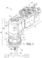
- a dense phase pump and manifold assembly 10 includes a dense phase pump 12 and a manifold 14.
- the dense phase pump 12 may be designed and operated generally in accordance with the 878 patent except as otherwise noted herein, for example, but alternatively many other dense phase pump designs may be used as needed.
- the dense phase pump pulls powder coating material from a coating material supply 16 and pushes the powder coating material to a spray gun 18.
- the supply 16 may be any suitable apparatus and design known in the art or later developed.
- a common example is a hopper that may have a fluidized bed, or alternatively, powder coating material can be supplied from a box or container or other suitable supply.
- the spray gun 18 may also be any suitable apparatus and design such that the spray gun receives a dense phase powder flow and produces a spray pattern that is suitable for a coating operation.
- a suitable dense phase spray gun is the PRODIGY® model spray gun available from Nordson Corporation, Westlake, Ohio.
- many other dense phase spray guns known in the art or later developed may be used.
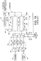
- Fig. 1A illustrates in simplified schematic form the basic parts of a dense phase pump 12, for example the pump disclosed in the 878 patent.
- a first control valve 20 is used to control the flow of powder coating material from the coating material supply 16 into an inlet 22 of the pump 12.
- a second control valve 24 is used to control the flow of powder coating material from an outlet 26 of the pump 12 to the spray gun 18.
- the pump 12 may be further realized using a pump chamber 28.
- the pump chamber 28 includes a gas permeable filter 30 that is disposed in a filter pressure chamber 32 with an annulus 34 that surrounds the gas permeable filter 30. Powder coating material is pulled into the pump chamber 28 by opening the first control valve 20 and applying negative pressure 36 (P - ) to the annulus 34.
- Powder coating material is pushed out of the pump chamber by closing the first control valve 20, removing the negative pressure P - , opening the second control valve 24 and applying positive pressure 38 (P + ) to the annulus 34.
- the first and second control valves 20, 24 thus are operated out of phase with each other, as is the application of the positive and negative pressures P + and P - .
- the control valves 20, 24 may each be realized in the form of a pneumatic pinch valve.
- a first powder flow Y-block 40 is used to provide inlet and outlet powder flow branches 44, 46 for the control valves 20, 24.
- the pinch valves 20, 24 may comprise an elastic material as described below, and in their natural relaxed condition are in an open position.
- positive pressure is applied to the pinch valve pressure chamber 43 associated with a pinch valve, the external pressure acting on the pinch valve body compresses or pinches the valve closed.
- the pressure chamber may be vented to atmosphere to release the pressure
- the pinch valve opens due to the natural elastic properties of the pinch valve body.
- negative pressure optionally may be applied to the pressure chamber 43 to further assist the pinch valve to return to the open position.
- each pinch valve is disposed in a respective pinch valve pressure chamber 43 in the pinch valve body (54). This allows the use of positive pressure 45 and optionally negative pressure 47 to be applied to the pinch valve pressure chamber 43 to close and open the pinch valve.
- each pinch valve 20, 24 may have its own separately controlled pressure to its associated pinch valve pressure chamber 43 to operate each pinch valve.
- a first barrier element or barrier filter 42 may be used in the pressure passage. A barrier element functions to prevent powder coating material from being drawn or blow back into a pressure source in the manifold 14 or into the ambient environment.
- barrier element is a porous filter that allows air to pass through but blocks a powder coating material.
- the barrier filters 42 used in commercial practice are disposed in the first Y-block 40.
- Each pinch valve may have an associated barrier element 42 for embodiments wherein each pinch valve is individually controlled.
- the manifold 14 provides the timing and supply for pressure applied to the pinch valve pressure chambers 43.
- the pump 12 may optionally include two pump chambers 28, 28' (we use a prime ' to indicate like parts for a two chamber pump) each having its own pair of control valves 20/20', 24/24'.
- a typical dense phase pump may have two gas permeable filters 30, 30' and four control valves 20/20', 24/24' and four barrier filters 42, 42'.
- the first Y-block 40 may be provided with four powder flow branches 44/44' and 46/46'.
- the use of the second pump chamber 28' also results in use of a second Y-block 48 because as the first pump chamber 28 is pulling powder from the supply 16, the second pump chamber 28' is pushing powder out to the spray gun 18 and vice-versa.
- the second Y-block 48 is disposed to provide powder flow branches 50, 50' and 52/52' between the supply 16, the spray gun 18 and the control valves 20/20', 24/24'.
- the control valves 20/20', 24/24' are positioned in a valve body 54, which may be transparent to allow observation of the operation of the control valves, as well as to detect a ruptured pinch valve. When a pinch valve ruptures, powder escapes into the pinch valve housing 72 and this will indicate to an operator to change out the pinch valve or the pinch valve housing 72 with new pinch valves.
- Powder coating systems frequently use many different types and color of powder coating material, and when the type or color of the powder coating material is changed, the pump 12 must be cleaned. Part of the cleaning operation is to purge the pump chambers 28, 28' as well as other portions of the powder flow paths.
- One of the purging options described in the 878 patent is to apply a purge gas 56 into an open or purge end 30b/30b' of the gas permeable filters 30, 30' that is opposite the single inlet/outlet end 30a/30a' of the gas permeable filters 30, 30'. Control of the purge timing and pressure source is carried out in the manifold 14.
- the filter pressure chambers 32, 32' along with the gas permeable filters 30, 30' are disposed in a pump housing 58.
- the pump housing 58 interfaces with the manifold 14 in order to provide the various pressure signals needed to operate the control valves 20/20', 24/24' and the pump chambers 28, 28'.
- the purge lines 56 separately attach to the pump housing 58 from the top of the pump housing and in-line with the check valve flow path.
- an embodiment of the dense phase delivery pump 12 in accordance with the present disclosure includes a first housing 60, which may include a pump body or housing 62 and a first or upper powder flow block or housing 64.
- the first housing 60 has a first pump chamber 66 and a second pump chamber 68 which each have respective gas permeable filters 70 associated therewith (see also Fig. 5 ).
- the gas permeable filters 70 are disposed in the pump body 62 although a lower portion of each may extend into the first powder flow block 64. Alternatively the gas permeable filters 70 may be fully disposed in the pump body 62.
- a pinch valve housing 72 preferably but not necessarily is a transparent unitary body that includes four pinch valve pressure chambers 74 (only two are shown in Fig. 4 ) that each receives a control valve 76.
- the control valves 76 are shown partially installed in their respective pinch valve pressure chambers 74.
- Each control valve 76 may be realized in the form of an elastic flexible pinch valve made of a suitable material, for example, natural rubber.
- the pump body 62 receives first and second check valve assemblies 78 which will be further described hereinbelow.
- the first powder flow block 64 may be attached to the bottom side of the pump body 62 with bolts 80, and includes powder flow branches that serve as inlet and outlet powder flow passages for the powder chambers 70a.
- a gasket 81 may also optionally be used to seal air passages between the pump body 62 and the first powder block 64.
- top, bottom, upper and lower are for convenience when viewing the drawings, but do not require that the dense phase pump 12 be oriented in any particular alignment during use; although a vertical or upright orientation as depicted in the drawings is common.
- the second flow block 82 provides powder flow branches 84, 86 (there are a total of four powder flow branches in the second powder flow block 82, two for each pump chamber 66, 68 for powder flow into and out of the pump chambers) respectively to a pump inlet connection 88 and a pump outlet connection 90.
- the pump inlet connection 88 is connectable to a powder supply 16 through a supply hose 92 and the pump outlet connection 90 is connectable to a spray gun 18 by a gun hose 94.
- the pinch valves 76 may be thought of as a wear item, meaning that due to the repetitive flexing of the pinch valve, the pinch valves 76 tend over time to weaken or wear out or rupture and need replacing.
- the barrier filters 96 may be disposed in the pinch valve housing 72 rather than in the upper Y-block (40) as done in prior designs.
- the barrier filters 96 are also wear items because the barrier filters 96 tend over time to become blocked or blinded with powder or at least to have reduced porosity.
- the pinch valves 76 and the barrier filters 96 are referred to herein as example of replaceable components (214, Fig. 3 ) because they tend to wear out over time and can be serviced so that the overall pump can continue in use. Other pump designs may use additional or different replaceable components.
- a single releasable fastener 98 is used to attach the second powder flow block 82 and the pinch valve housing 72 to the pump housing 60.
- the second powder flow block 82 and the pinch valve housing 72 may be attached to the first powder flow block 64 using the single releasable fastener 98. In this manner, by simply loosening or releasing the single releasable fastener 98, the pinch valve housing 72 can be removed from the pump housing 60 for access to the replaceable components 76, 96 (214).
- the replaceable components (214) can be replaced individually as needed.
- the entire pinch valve housing 72 with replacement components as a discrete assembly can be installed in place of the previously installed pinch valve housing 72. Reassembly is also simplified by using the single releasable fastener 98.
- the single releasable fastener 98 may be realized in the form of an end threaded bolt, however, many other types of releasable fasteners may alternatively be used.
- the single releasable fastener 98 can be completely withdrawn. It is important to note that the single releasable fastener concept may be used in dense phase pumps other than the exemplary embodiment herein, for example, with the dense phase pump described in the 878 patent or others known or later developed.
- the single releasable fastener 98 extends through a central bore 100d of a multi-section column 100.
- the column 100 is centrally located with respect to the pinch valve 76 locations, for example, along a central longitudinal axis X of the dense phase pump 12.
- the pinch valves 76 may be uniformly spaced about the central longitudinal axis of the pinch valve housing 72.
- the pinch valves 76 may be disposed approximately ninety degrees apart from each other. The central location of the column 100 then facilitates an even distribution of compressive forces as the fastener 98 is tightened.
- a first column section 100a is centrally positioned in the second powder flow block 82; a second column section 100b extends centrally through the pinch valve housing 72, and a third column section 100c is centrally positioned in the first powder flow block 64 (see also Figs. 11 and 11A ).
- the column 100 therefore may be realized with sections 100a-100c with each column section comprising a single central opening in the associated body that the single releasable fastener 98 extends through or into.
- the pinch valve housing 72 includes the central column section 100b that extends all the way through the pinch valve housing 72 and provides a single central opening for the single releasable fastener.
- the column 100 may be integrally formed as part of the second powder flow block 82 (column section 100a), the pinch valve housing 72 (column section 100b), and the first powder flow block 64 (column section 100c).
- the three sections 100a-100c all align axially with each other so that the single releasable fastener 98 extends through the central bore 100d and into all three sections 100a-100c and may have a threaded end 98a that can be screwed into a threaded insert 102 in the first powder flow block 64.
- the threaded insert 102 may comprise metal such as brass for example, and may contact a metal spring 103 in order to provide electrical ground for the fastener 98.
- the pinch valves 76 each include two end flanges (194) that will be further described below. These end flanges are axially compressed when the single releasable fastener 98 is tightened to form tight seals so that powder coating material flowing through the pinch valves 76 does not by-pass around the pinch valves and escape into or out of the pinch valve body 72. It is useful then that the single releasable fastener 98 be sufficiently robust and tightened so that the pinch valves 76 are adequately compressed to seal.
- the single releasable fastener 98 may include a socket 98b that accepts an Allen wrench to allow sufficient torque to be applied to the fastener 98.
- the multi-section column 100 functions as a stop mechanism to prevent over-torque being applied to the single releasable fastener 98.
- the first column section 100a has an upper distal end 104 that contacts a lower distal end 106 of the second column section 100b; and the second column section 100b has an upper distal end 108 that contacts a lower distal end 110 of the third column section 100c.
- the distal ends 104, 106, 108, 110 make contact so as to form the continuous central bore 100d within a continuous supporting column 100.
- the distal ends 104, 106, 108 and 110 make full contact at a predetermined or controlled compression of the pinch valves 76. Once all three column sections 100a-c are in full contact, additional axial movement or compression of the three bodies 82, 72 and 64 is prevented and the pinch valves 76 cannot be further compressed or over-compressed.
- the facing contacting surface pairs namely the distal ends 104/106 between the upper side (220) of the pinch valve housing 72 and the lower side (222) of the first powder flow block 64, and the distal ends 108/110 between the lower side (224) of the pinch valve housing 72 and the upper side (226) of the second powder flow block 82, function as positive stops to prevent over-tightening or over-torque of the single releasable fastener 98 which could otherwise over compress or damage the pinch valve end flanges (194).
- the manifold 14 provides purge air to the dense phase pump 12.
- One of the purge modes that can be used is to direct a flow of pressurized air longitudinally through each gas permeable filter 70.
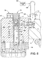
- the dense phase pump 12 includes the pair of pump chambers 66, 68 (only the pump chamber 68 is visible in Figs. 5-7 ).
- the pump chamber 68 includes a bore 112 that extends through the pump body 62. Disposed within the bore 112 is the check valve assembly 78 and a gas permeable filter 70. Seals 114, such as o-rings for example, provide pressure tight seals at either end of the gas permeable filter 70 so that a portion of the bore 112 serves as the pressure chamber 32 ( Fig. 1A ) volume with a portion of the bore 112 wall providing a pressure chamber wall 116 about the gas permeable filter 70 disposed therein.
- the gas permeable filter 70 may be a hollow cylinder comprising a gas porous material such as, for example, porous polyethylene. This same material may also be used for the barrier filter discs 96.
- the central volume 70a of the hollow cylinder thus serves as a powder chamber by which powder is drawn into and pushed out of the dense phase pump 12.
- the gas permeable filter 70 fits within the pressure chamber wall 116 so as to provide an annulus 118 that serves as a pressure chamber for the gas permeable filter 70.
- the annulus 118 is in fluid communication (not shown in Fig. 5 ) with sources of the positive pressure 38 (P + ) and negative pressure 36 (P - ) ( Fig.
- each gas permeable filter 70 may be received in a counterbore 120 that may be in the first powder flow block 64, and aligned so that the powder chamber 70a is in fluid communication with an inlet powder flow branch 122 and an outlet powder flow branch 124 which in turn are in fluid communication with associated pinch valves 76.
- the pump body 62 is attached to the manifold 14 by bolts 126 ( Figs. 1 and 2 ).
- the manifold 14 in part is an air manifold that provides various pressure signals and conditions to the dense phase pump 12, including pressure for the pump chambers 66, 68, purge air 56 ( Fig. 1A ), and pressure for the pinch valves 76. Therefore, we provide a sealed interface 128 between the pump body 62 and the manifold 14 for air passages (not shown) to pass therebetween.
- a back side 130 of the pump body 62 presents a first planar surface 132 that faces a second planar surface 134 that is presented by a front side 136 of the manifold 14.
- the sealed interface 128 is compressed between the two facing planar surfaces 132, 134 when the bolts 126 are tightened down.
- the sealed interface 128 may be realized, for example, with a gasket 138.
- the check valve assembly 78 includes a check valve body 140 that may be threadably installed in a threaded portion of the bore 112 wall. Seals 142 such as o-rings provide a sealed chamber 144 that is provided in the pump body 62 about a portion of the check valve body 140.
- a purge inlet bore 146 is provided in the pump body 62.
- a coupler 148 having an air passage 148a therethrough is installed in one end of the purge inlet bore 146 and inserts into a purge outlet bore 150 in the manifold 14.
- the purge outlet bore 150 receives purge air from a purge air source 152 through an air fitting 154 in the manifold 14.
- Timing and control of the purge air is provided by valves and controls in the manifold 14.
- the coupler 148 bridges the interface 128 between the pump body 62 and the manifold 14 to provide a pressure tight sealed air passage 148a for purge air from the manifold 14 into the pump body 62.
- a seal 156 such as an o-ring, for example, may be used to seal the coupler 148 in the manifold purge outlet bore 150.
- the purge inlet bore 146 opens to the sealed chamber 144 and therefore provides a purge air inlet 146a to the check valve assembly 78 via the sealed chamber 144.
- the manifold purge outlet bore 150 provides a purge air outlet 150a from the manifold 14 that is in fluid communication with the purge air inlet 146a to the check valve assembly 78.
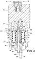
- a check valve plug 158 may be threadably attached to the check valve body 140 and includes a hollow cylindrical extension 160.
- the cylindrical extension 160 is provided with one or more through ports or holes 162 that establish fluid communication between the sealed chamber 144 and an interior cavity 164 of the check valve body 144.
- Disposed within the check valve cavity 164 is a ball type check valve 166.
- the interior cavity 164 of the check valve body 144 is in fluid communication with the powder chamber 70a only when the check valve is open.
- the check valve 166 includes a sleeve-like valve seat member 168 that provides a valve seat 168a; a valve member 170, for example a ball; and a biasing element 172, for example, a spring.
- the spring 172 is disposed between the valve member 170 and the valve seat 168 in a compressed condition so as to urge the ball 170 into sealing engagement with the valve seat 168a.
- the check valve 166 is therefore in a normally closed condition with the ball 170 urged against the valve seat 168a in the absence of purge air pressure.
- the check valve 166 When purge air is supplied to the check valve 166, the check valve remains closed until the purge air pressure exceeds the cracking or opening pressure of the check valve 166.
- the opening pressure of the check valve 166 can be controlled by appropriate selection of the strength of the biasing element 172.
- the valve member 170 moves away from the valve seat 168a and purge air flows through the check valve 166 and into the powder chamber 70a to purge powder therefrom.
- the valve seat cage 168 may optionally include a second valve seat member 174 that presents a second valve seat 174a on the downstream end of the valve seat cage. This valve seat may be used to cutoff purge flow in the event of an overpressure condition in the purge supply.
- the second valve seat 174 may be sealed in the check valve body 140 by a seal 176 such as an o-ring, for example.
- the flow path of purge air when the check valve 166 is open is represented schematically by the arrow 178 (see Figs. 6 and 7 ).
- the purge air 178 enters the pump body 62 from the coupler 148 that is in fluid communication with the purge air supply 152.
- the purge air 178 flows into the sealed chamber 144 and because the chamber is sealed, the purge air is forced up towards and through the holes 162.
- the purge air pressure exceeds the opening pressure of the check valve 166, the ball 170 unseats from the valve seat 168a and purge air 178 flows along the flow axis of the check valve 166 and passes into and through the powder chamber 70a. From Fig.
- the purge air can pass all the way through to the spray gun 18 and purge the spray gun at the same time, as well as purge the powder paths all the way back to the powder supply 16 if so needed.
- the purge air 178 enters the gas permeable filter 70 at the open purge end 180 (corresponding to 30b in Fig. 1A ) thereof that is opposite the open end 182 (corresponding to 30a in Fig. 1A ) that serves as both the inlet and outlet of the pump chamber 68 for powder flow.
- purge air enters the gas permeable filter 70 through the same open end 30b of the gas permeable filter 30 but is supplied through an air hose and connector that are mounted on top of the check valve assembly meaning that, in the 878 patent, the purge air is supplied to the check valve in-line or coaxial with the flow axis 186 of the check valve and the longitudinal axis 188 of the gas permeable filter 30.
- the purge air is supplied to the check valve in-line or coaxial with the flow axis 186 of the check valve and the longitudinal axis 188 of the gas permeable filter 30.
- the purge air 178 enters the purge air inlet 146a of the check valve assembly 68 off-axis from the longitudinal axis 188 of powder flow through the gas permeable filter 70, which is optionally in-line or coaxial with the flow axis 186 of the check valve 166.
- the illustrated embodiment shows that the purge air 178 enters the pump body 62 along a purge flow directional inlet axis 184 that is transverse the directional flow axis 186 of the check valve 166.
- the check valve directional flow axis 186 may be but need not be in-line with the longitudinal axis 188 of the gas permeable filter 70 and the powder chamber 70a.
- the purge air 178 enters the pump body 62 and flows into the check valve assembly 68 along a purge flow inlet axis 184 that is transverse the longitudinal axis 188 of the gas permeable filter 70.
- the purge air 178 then flows along a flow path that forces the purge air to change direction by ninety degrees as it enters the check valve 166 so that the purge air flow is in-line with the check valve flow axis 186 and thus also in-line with the longitudinal axis 188 of the gas permeable filter 70 and the powder chamber 70a.
- a benefit of the transverse inlet flow of the purge air is that it facilitates supplying the purge air from a side mounted arrangement between the pump body 62 and the manifold 14. This completely eliminates the need for top mounted purge hoses connected between the check valve assembly 68 and the manifold 14.
- the off-axis angle of the inlet purge air flow which is defined as being the angle between the purge flow inlet axis 184 and the longitudinal axis 188 of the gas permeable filter 70 and the powder chamber 70a, is not critical.
- the check valve 166 orientation still provide an outlet flow of the purge air that is in-line with the gas permeable filter 70 longitudinal axis.
- the ninety degree turn of the purge air flow path could occur within the check valve 166 itself.
- the pinch valve 76 includes a pinch valve body 190 with a central passage 192 therethrough along a longitudinal axis X.
- the pinch valve 76 further includes first and second end flanges 194 that may be the same size and shape. By having the end flanges 194 be the same, it does not matter whether the pinch valve 76 is installed in a first longitudinal orientation into the pinch valve housing 72, or is flipped around and installed in the inverse longitudinal orientation.
- the pinch valve 76 may further have a pair of diametrically opposed and longitudinally extending ribs 196 along opposite sides of the valve body 190. These ribs 196 provide a localized stiffness to the pinch valve body 190 so that when the pinch valve is exposed to external positive pressure, the portions 198 of the pinch valve body between the ribs 196 act as hinge points to allow the pinch valve to close without high stresses on the valve body 190.
- the pinch valve 76 is closed off by having the major sides 192a of the cats-eye passage 192 being compressed together under force of pneumatic pressure, with the ribs 196 reducing stress on the valve body.
- the elastic ribs 196 are in tension so that when the pressure is released or vented, the ribs 196 assist in returning the pinch valve 76 to an open position.
- the pinch valve body 192 shape includes generally elliptical portions when viewed in transverse cross-section. This shape allows the pinch valve to open and close by the outer ends of the ellipses to act as hinge points when the pinch valve is closed.
- the end flanges 194 may each include a peripheral shape or profile when viewed in plan ( Fig. 9 ) that assists in assembly of the pinch valve 76 into the pinch valve pressure chamber 74 in the pinch valve housing 72.
- the ribs 196 preferably fit inside corresponding longitudinal slots 200 provided in the pinch valve pressure chamber 74 (note that in Fig. 8B the slots 200 and the pressure chamber 74 are illustrated in schematic fashion).
- the end flanges 194 each then has a non-circular peripheral shape.
- Fig. 9 shows all four pinch valve 76 installed in the pinch valve housing 72.
- the flats 202 form a visual appearance as an arrow head or pointer to an assembler (as represented by the arrows 204 in Fig. 9 ) that points to the center of the pinch valve body 72, for example the center column 100. This helps the assembler locate the ribs 196 into the corresponding slots 200 in the pinch valve pressure chamber 74.
- the flats 202 therefore act as alignment indicia in assisting the assembler to install the pinch valve in a proper orientation.
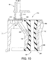
- the flats 202 may be provided optionally in only the upper surface portions of the associated end flanges 194 so that the end flanges 194 have radially symmetric seal surfaces 206 (also see Fig. 10 ) within the pinch valve housing 72.
- the dashed lines R in Fig. 9 show the alignment of the ribs 196 and the slots 200 which are not otherwise visible in the drawing.
- each pinch valve 76 is disposed in a pinch valve pressure chamber or bore 74 (corresponding to 43 in Fig. 1A ) in the pinch valve housing 72.
- the pinch valve pressure chamber 74 generally conforms to the elliptical shape of the pinch valve body 190.
- the pinch valve end flanges 194 are sealingly compressed when the pinch valve housing 72 is assembled between the first powder flow block 64 and the second powder flow block 82.
- the pinch valve pressure chamber 74 receives pressure via a pneumatic pressure passage 208, depending on whether the pinch valve 76 is to be in an open or closed position.
- the pinch valve pressure chamber 74 shares the same longitudinal axis X as the pinch valve 76 disposed therein.
- the pressure passages that open to the pinch valve pressure chamber are formed at ninety degrees from the longitudinal axis of the pinch valve pressure chamber.
- the air pressure from the manifold enters the pinch valve housing from the top end and then a pressure passage is first drilled down into the pinch valve body and then cross-drilled for access to the pinch valve pressure chamber.
- the pressure passage 208 may be formed at an oblique angle relative to the longitudinal axis of the pinch valve pressure chamber 74.
- the pressure passage 208 has an oblique entry angle ⁇ to the pinch valve pressure chamber 74.
- the obliquely angled pressure passage 208 may extend, for example, from an inlet port 209 to the pinch valve pressure chamber 74.
- the oblique angle ⁇ may in some cases be easier to form in the pinch valve housing 72, and also may provide a more effective entry for the air pressure in to the pressure chamber 74.
- a respective barrier element 96 for example a barrier filter in the form of a flat disc 96, is disposed in a port 209 that is provided in the upper side 220 of the pinch valve housing 72.
- the port 209 is in fluid communication with the pneumatic flow passage 208.
- Pneumatic pressure is provided through an associated pneumatic branch 210 in the first powder flow block 64.
- the first powder flow block 64 in addition to providing the powder flow branches between the pinch valves 76 and the gas permeable filters 70, also provides the pneumatic branches for positive pressure from the manifold 14 to the pinch valve pressure chambers 74 in the pinch valve housing 72.
- the barrier elements 96 in this disclosure may be disposed in the pinch valve housing 72 so that they are accessible and easily replaceable when the single releasable fastener 98 is loosened.
- a suitable seal 212 such as an o-ring for example, may be used to provide a pressure tight seal between the pneumatic branch 210 of the first powder flow block 64 and the pneumatic pressure passage 208 in the pinch valve housing 72.
- the pinch valves 76 and the barrier filter discs 96, as well as the seals 212 are therefore examples of replaceable components 214 ( Fig. 3 ) that are readily accessible when the pinch valve housing 72 is separated from the first powder flow block 64.
- the replaceable components 214 typically will be wear items that over time and repeated operation of the dense phase pump 12 need to be replaced either as a repair action or during routine maintenance.
- the pinch valve 250 includes a generally cylindrical body 252 with a central passage 254 therethrough.
- the central passage 254 may have but need not have a non-circular cross-section shape, for example the shape may be like a cats-eye shape, and the pinch valve body may have an elliptical shape in lateral cross-section.
- the pinch valve 250 may also include diametrically opposed ribs 256 and drawing lines 256a on the end flange surfaces (278) are shown to indicate the rib 256 diametric and directional orientation.
- a first difference between the pinch valve 250 and the pinch valve 76 is that the upper end flange 258 and the lower end flange 260 are radially offset from one another. As will be additionally explained below, this radial offset is provided to accommodate the location of the slots in the pinch valve pressure chamber that receive the ribs 256.
- the drawings show a first alignment axis 262 for the upper end flange 258 and a second alignment axis 264 for the lower end flange 260 (best understood from Fig. 8D ).
- the pinch valve 250 may still be reversible in the sense that it may be installed in the orientation of Fig. 8C or flipped around with the lower end flange 260.
- the alignment axes 262, 264 are referenced to an outermost radial extent of the respective end flanges 258, 260.
- the end flanges 194 of Figs. 8A and 8B are non-circular, in contrast to the pinch valves of the 878 patent for example.
- the end flanges 258, 260 are also non-circular but have a more defined pointing profile as best viewed in Fig. 8D .
- the end flanges 258, 260 are radially offset from each other, they may otherwise be the same or matching shape so that the pinch valve 250 can be installed in a first longitudinal orientation or flipped around and installed in an inverse longitudinal orientation.
- each end flange 258, 260 may still be circular, but two straight portions 270, 272 blend to a more defined point or pointer apex 274 that delimits a radially outermost radial extent of each end flange 258, 260.
- each end flange 258, 260 presents a more visually perceptible directional or orientation indication for aligning the pinch valves 250 during assembly into the pinch valve housing so that the pinch valves 250 "point" towards the center of the pinch valve housing 72, for example, radially towards the column 100.
- alignment indicia for example optional directional arrows 276, may be provided on the outer surfaces 278 of the end flanges 258, 260.
- the directional arrows 276 may be molded into the pinch valve body 252 or otherwise provided as needed. Note that the directional arrows 276 directionally align with the pointer apex 274.
- the alignment axes 262, 264 indicate a radial offset included angle ⁇ between the end flanges 258, 260 when viewed in plan. Moreover, the alignment axes 262, 264 also indicate a radial offset included angle ⁇ between each pointer apex 274 and the rib alignment directional axis 256a. In other words, the alignment profile of the end flanges 258, 260 are not only radially offset from each other but also from the ribs 256.
- the ribs when used as part of the pinch valve 250 (or 76 in the embodiment of Figs. 8A and 8B ), are to be aligned with and received in the slots in the pinch valve pressure chamber.
- the slots 200 are formed at right angles with respect to the slots 200 in each adjacent pinch valve pressure chamber 74 on either side thereof, as indicated by the lines R (the lines R indicate the rib orientation).
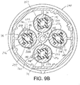
- the slots 200 and the ribs 196 are oriented in a manner similar to what was done in the 878 patent (which discloses a square pinch valve housing), but this results in the ribs 196 partially obstructing the pressure passage 208 in the location or area where the pressure passage 208 opens to the pressure chamber 74, for example when the pinch valve housing 72 is now of a generally compact cylindrical shape.
- a pinch valve housing 290 is provided with slots 292 that receive the pinch valve ribs 256.
- the slots 292 are radially offset by an angle relative to the location or area where the pressure passage 208 opens to the pressure chamber 74 so that the ribs 256 do not interfere with pressurizing the pressure chamber 74.
- the slots 292 may be rotated by approximately 37° away from the where the pressure passage 208 opens to the pressure chamber 74. This moves the ribs 256 out of the way of where the pressure passage 208 opens to the pinch valve pressure chamber 74.
- the pressure passage 208 faces a flatter portion of the pinch valve body that is between the rib 196 and the hinge 198, as this helps compress the pinch valve closed.
- This is best understood from Fig. 9B .
- the angle of radial offset between the ribs 256 and the opening of the pressure passage 208 to the pressure chamber 75 will depend on the shape, design, dimensions and so forth of the pinch valve housing 72 as well as the design of the pinch valve 250, particularly the shape of the elliptical portions. Therefore, 37° is but one example of a radial offset that assures that the pressure passage 208 does not open to the pressure chamber 74 in an orientation that would be obstructed by the ribs 256.
- this radial offset between the ribs 256 and the opening of the of the pressure passage 208 to the pressure chamber 74 assures that the pressure chamber 208 does not open to the pressure chamber 74 facing the hinge location 198 ( Fig. 9B ) because if that were the case then, when the pinch valve is in a closed position, the pinch valve hinge area 198 could obstruct the pressure passage 208 and the pressure passage 208 might not be vented to re-open the pinch valve.
- pressure passage 208 may be formed at an oblique entry angle ⁇ to the pinch valve pressure chamber 74 as described hereinabove.
- this angle is determined by the radial offset angle between the ribs 256 and the opening of the pressure passage 208 to the pressure chamber 74.
- the orientation of the pressure chamber 74 (as measured from the plane which bisects the pinch valve ribs) rotates about the longitudinal center axis of the pinch valve housing 72.
- an angle from the horizontal plane when viewed from the top as shown in Figs.
- the selection of the angle ⁇ determines the angle ⁇ if it is desired to have the pinch valve 250 installable in either longitudinal orientation. And the selection of the angle ⁇ may be made based on the specific needs to pressurizing the pinch valve pressure chamber 74, such as the location where the pressure passage 208 opens to the pressure chamber 74 and the shape and design of the pinch valve 250. Therefore, the exemplary values for ⁇ and ⁇ as well as the radial offset angle between the ribs 256 and the pressure passage 208 opening to the pressure chamber 74, may be chosen based on the specific geometries of a particular pinch valve housing.
- the pinch valve housing 72 can be separated from the first powder flow block 64 for access to the replaceable components 214 such as the pinch valves 76 and the barrier filter discs 96 and the o-rings 212. These replaceable components can be replaced without any further disassembly of the dense phase pump 12, although optionally the pinch valve housing 72 can be also separated from the second powder flow block 82 when the single releasable fastener 98 is removed. This may be done, for example, if the entire pinch valve housing 72 is to be swapped or replaced with a different pinch valve housing 72.
- the pinch valve housing 72 can be readily accessed for servicing to replace the replaceable components 214 and/or the pinch valve housing 72 itself without having to remove any hoses that are connected to the dense phase pump 12 during normal operation.
- the pinch valve housing 72 may be serviced without removing the supply hose 92 or the gun hose 94 from the second powder flow block 82 ( Fig. 1 ); or for embodiments in which the 878 type of purge connections are used, without removing the purge air hoses from the check valves.
- An exemplary method for replacing one or more replaceable components includes the step of loosening the single releasable fastener 98 so as to release the axial compression between the first powder flow block 64, the pinch valve housing 72 and the second powder flow block 82.
- the first housing 60 ( Fig. 1 ) can remain attached to the manifold 14 if so desired.
- the first powder flow block 64 may be attached to the pump body 62 using the fasteners 80 such as a plurality of bolts.
- the pinch valve housing 72 may be serviced without separating the first powder flow block 64 from the pump body 62 or the pump body 62 from the manifold 14.
- the pinch valve housing 72 may be axially pulled away or separated from the first powder flow block 64 (note that although the exemplary embodiments illustrate the dense phase pump 12 in a vertical orientation as is done in common practice, such is not required for operation of the pump).
- the replaceable components 214 such as one or more of the pinch valves 76, the barrier elements 96 and the seals 212, may be replaced with different or new ones.
- the pinch valve assembly housing 72 may be further separated from the second powder flow block 82 and wholly replaced, or in some cases it may be easier to service the replaceable components 214 with the pinch valve housing also separated from the second powder flow block 82 as a standalone assembly.
- the dense phase pump 12 can be reassembled by mating up the pinch valve housing 72 with the first powder flow block 64 and the second powder flow block 82 with the pinch valve housing 72 and then tightening the single releasable fastener 98.
- alignment structures may be provided. Proper radial alignment, for example, of the pinch valve housing 72 relative to the first and second powder flow blocks 64, 82, assures that the various pneumatic and powder flow passages which extend between these bodies are correctly aligned and sealed.
- a first alignment concept contemplates keyed elements 215 ( Fig. 4 ) on the attachable bodies so as to assure proper radial alignment.
- the pinch valve housing 72 may be provided with one or more extensions or tabs 216 that are circumferentially disposed about the outer periphery of the pinch valve housing 72.
- tabs 216 mate with conforming slots 218 that are circumferentially disposed about the outer peripheries of the first and second powder flow blocks 64, 82.
- Each tab 216a on the pump facing side 220 of the pinch valve housing 72 is received in a conforming slot 218a on the pinch valve facing side 222 of the first powder flow block 64.
- each tab 216b on the opposite facing side 224 of the pinch valve housing 72 is received in a conforming slot 218b on the pinch valve facing side 226 of the second powder flow block 82.
- the mating tabs 216 and conforming slots 218 may be disposed slightly radially inward along the outer wall 228 of the pinch valve housing 72 so that the keyed elements 215 are enclosed when the pinch valve housing 72 is assembled with the first and second powder flow blocks 64, 82.
- the keyed elements 215 may be located elsewhere other than along the outer peripheries if so needed, and may have any suitable shape or geometry.
- the tabs 216 and the conforming slots 218 may be keyed to each other by having at least one of the tabs 216 and its conforming slot 218 on each side 220, 224 of the pinch valve housing 72 be of a different size or shape than the others.
- the pinch valve housing 72 can be assembled to the first and second powder flow blocks 64, 82 in only one radial orientation and the keyed elements 215 may also be selected so that the pinch valve housing 72 can be assembled in only one axial orientation (for example, only with the first side 220 assembled with the first powder flow block 64 and not upside down).
- the keyed elements 215 need only be designed to provide radial alignment.
- the keyed elements 215 also cooperate to restrict relative rotation between the pinch valve housing 72 and the first and second powder flow blocks 64, 82.
- This may be realized, for example, by providing a close dimensional fit between the tabs 216 and the conforming slots 218 so that the assembled keyed elements 215 restrict relative rotation between the pinch valve housing 72 and the first and second powder flow blocks 64, 82.
- the close dimensional fit between the tabs and slots amounts to an interference fit is a matter of design choice.
- the close dimensional fit is sufficient to prevent relative rotation between the assembled bodies but not so tight so as to make assembly or disassembly less useful. From these teachings, many other ways to provide a keyed connection and alignment between the assembled bodies 72, 64 and 82 will be readily apparent to those skilled in the art.
- the keyed elements 215 may be disposed as needed on the several mating bodies.
- the tabs 216 may be provided on the first and second powder flow blocks 64, 82 and the slots 218 disposed on the pinch valve housing 72.
- all three bodies 72, 64 and 82 may have tabs and slots that cooperate with conforming tabs and slots on the facing sides of the attached bodies.
- the keyed elements 215 restrict the pinch valve housing 72 to being assembled in preferably a single radial position relative to the first and second powder flow blocks 64, 82.
- the differently shaped or sized keyed elements 215 may be visually distinct to an assembler, such may not always be the case.
- exterior alignment indicia 230 may be provided.
- Each of the pinch valve housing 72, the first powder flow block 64 and the second powder flow block 82 may include an exterior alignment indicia 230 that aligns with the adjacent body to indicate correct radial alignment.
- the exterior alignment indicia may be in the form of one or more directional pointers 232 on the outer surface 234 of the pinch valve housing 72 that align with directional pointers 236 on the respective outer surfaces 238, 240 of the first powder flow block 64 and the second powder flow block 82 when the bodies are radially aligned.
- the exterior alignment indicia 230 may have any suitable form and appearance.
- the exterior alignment indicia 230 may be embossed raised surfaces or reliefs on the outer surfaces 234, 238 and 240, or may be applied on labels or printed on, or any other suitable technique may be used as needed.
- the exterior alignment indicia 230 may be used to assist in the assembly of the dense phase pump 12, and after the pump is assembled and the single releasable fastener 98 tightened, the exterior alignment indicia 230 provide visual confirmation that the pinch valve housing 72 is properly and radially aligned with the first and second powder flow blocks 64, 82.
Landscapes
- Engineering & Computer Science (AREA)
- General Engineering & Computer Science (AREA)
- Mechanical Engineering (AREA)
- Physics & Mathematics (AREA)
- Fluid Mechanics (AREA)
- Nozzles (AREA)
- Details Of Reciprocating Pumps (AREA)
- Jet Pumps And Other Pumps (AREA)
- Coating Apparatus (AREA)
- Check Valves (AREA)
Claims (15)
- Ein Quetschventilgehäuse, aufweisend einen Körper, aufweisend zumindest eine Druckkammer (74), ein Quetschventil (76, 250), das in der Druckkammer (74) angeordnet ist, und eine Einlassöffnung (209), die in Fluidverbindung mit der Druckkammer (74) steht, dadurch gekennzeichnet, dass die Einlassöffnung (209) in der Oberseite (220) des Quetschventilgehäuses vorgesehen ist, wobei das Quetschventilgehäuse ferner einen Druckdurchgang (208), der sich von einer Einlassöffnung (209) zu der Druckkammer (74) erstreckt, und ein Sperrelement (96), das in der Einlassöffnung (209) angeordnet ist zum Bereitstellen eines vereinfachten Zugangs zum Ersetzen des Sperrelements (96), aufweist.
- Quetschventilgehäuse nach Anspruch 1, wobei das Sperrelement einen Sperrfilter aufweist, der ein gasdurchlässiges Material aufweist.
- Quetschventilgehäuse nach Anspruch 1, wobei das Sperrelement (96) betriebsbereit ist, um Pulver am Eintreten in einen Druckdurchgang (208) zu blockieren, der in Fluidverbindung mit der Druckkammer (74) steht.
- Quetschventilgehäuse nach Anspruch 3, wobei der Druckdurchgang (208) abwechselnd Überdruck und Unterdruck an die Druckkammer (74) anlegt.
- Quetschventilgehäuse nach Anspruch 1, aufweisend einen Druckdurchgang (208) mit einer Öffnung in die Druckkammer (74).
- Quetschventilgehäuse nach Anspruch 5, wobei das Quetschventil (76, 250) Rippen (196, 256) aufweist, die in Schlitzen (200) in dem Körper aufgenommen sind, wobei die Schlitze (200) radial um einen Winkel β von der Öffnung versetzt sind.
- Quetschventilgehäuse nach einem der Ansprüche 3 bis 6, wobei der Druckdurchgang sich von der Einlassöffnung zu der Druckkammer erstreckt, wobei die Druckkammer eine Längsachse X aufweist, und wobei sich der Druckdurchgang zu der Druckkammer unter einem schrägen Winkel θ relativ zu der Längsachse X öffnet.
- Quetschventilgehäuse nach einem der vorstehenden Ansprüche, aufweisend Ausrichtungsanzeigen (230) an einer äußeren Fläche des Körpers.
- Eine Dichtstrompulver-Pumpe, umfassend:ein erstes Gehäuse (60), einen gasdurchlässigen Filter (70), der in dem ersten Gehäuse (60) angeordnet ist, undein Quetschventilgehäuse (74) wie in einem der vorstehenden Ansprüche beansprucht.
- Dichtstrompumpe nach Anspruch 9, aufweisend das Quetschventilgehäuse nach Anspruch 8, wobei das erste Gehäuse (60) externe Ausrichtungsanzeigen (230) aufweist, die in Kombination mit den Ausrichtungsanzeigen (230) an dem Körper das Quetschventilgehäuse (72) mit dem ersten Gehäuse (60) während der Montage der Dichtstrompumpe ausrichten.
- Dichtstrompumpe nach Anspruch 9, wobei das Quetschventilgehäuse (72) und das erste Gehäuse (60) aufeinander abgestimmte Elemente (215) zum Ausrichten des Quetschventilgehäuses (72) mit dem ersten Gehäuse (60) während des Montierens der Dichtstrompumpe aufweist.
- Dichtstrompumpe nach Anspruch 11, wobei die aufeinander abgestimmten Elemente (215) die Rotation des Quetschventilgehäuses (72) relativ zu dem ersten Gehäuse (60) begrenzen.
- Dichtstrompumpe nach einem der Ansprüche 9 bis 12, aufweisend einen zweiten gasdurchlässigen Filter (70), der in dem ersten Gehäuse (60) angeordnet ist, und das Quetschventilgehäuse (72) dazu angepasst ist, zumindest vier Quetschventile (76, 250) aufzunehmen.
- Dichtstrompumpe nach Anspruch 13, aufweisend zumindest vier Sperrelemente (96), welche in dem Quetschventilgehäuse (72) angeordnet sind.
- Dichtstrompumpe nach einem der Ansprüche 9 bis 14, wobei das erste Gehäuse einen Pumpenkörper (62) und einen ersten Pulverströmungs-Block (64) und eine Vielzahl von Befestigungsmitteln (103) zum Befestigen des ersten Pulverströmungs-Blocks (64) an dem Pumpenkörper (62) aufweist, wobei die Dichtstrompumpe einen zweiten Pulverströmungs-Block (82) aufweist, wobei das Quetschventilgehäuse (72) zwischen dem ersten Pulverströmungs-Block (64) und dem zweiten Pulverströmungs-Block (82) angeordnet ist, wobei das einzige lösbare Befestigungsmittel (98) den zweiten Pulverströmungs-Block (82) und das Quetschventilgehäuse (72) mit dem ersten Pulverströmungs-Block (64) befestigt.
Applications Claiming Priority (2)
| Application Number | Priority Date | Filing Date | Title |
|---|---|---|---|
| US13/837,169 US20140261739A1 (en) | 2013-03-15 | 2013-03-15 | Dense phase pump with easily replaceable components |
| EP14159865.6A EP2777821B2 (de) | 2013-03-15 | 2014-03-14 | Dichtstrompumpe mit leicht auswechselbaren Komponenten |
Related Parent Applications (2)
| Application Number | Title | Priority Date | Filing Date |
|---|---|---|---|
| EP14159865.6A Division EP2777821B2 (de) | 2013-03-15 | 2014-03-14 | Dichtstrompumpe mit leicht auswechselbaren Komponenten |
| EP14159865.6A Division-Into EP2777821B2 (de) | 2013-03-15 | 2014-03-14 | Dichtstrompumpe mit leicht auswechselbaren Komponenten |
Publications (2)
| Publication Number | Publication Date |
|---|---|
| EP3175925A1 EP3175925A1 (de) | 2017-06-07 |
| EP3175925B1 true EP3175925B1 (de) | 2019-12-18 |
Family
ID=50277076
Family Applications (3)
| Application Number | Title | Priority Date | Filing Date |
|---|---|---|---|
| EP17152724.5A Active EP3175925B1 (de) | 2013-03-15 | 2014-03-14 | Quetschventilrestriktor |
| EP17152721.1A Active EP3181238B2 (de) | 2013-03-15 | 2014-03-14 | Form kodierte quetschventile. |
| EP14159865.6A Active EP2777821B2 (de) | 2013-03-15 | 2014-03-14 | Dichtstrompumpe mit leicht auswechselbaren Komponenten |
Family Applications After (2)
| Application Number | Title | Priority Date | Filing Date |
|---|---|---|---|
| EP17152721.1A Active EP3181238B2 (de) | 2013-03-15 | 2014-03-14 | Form kodierte quetschventile. |
| EP14159865.6A Active EP2777821B2 (de) | 2013-03-15 | 2014-03-14 | Dichtstrompumpe mit leicht auswechselbaren Komponenten |
Country Status (5)
| Country | Link |
|---|---|
| US (4) | US20140261739A1 (de) |
| EP (3) | EP3175925B1 (de) |
| JP (3) | JP6448912B2 (de) |
| CN (2) | CN107716148B (de) |
| DE (1) | DE202014011108U1 (de) |
Families Citing this family (13)
| Publication number | Priority date | Publication date | Assignee | Title |
|---|---|---|---|---|
| US20140261739A1 (en) | 2013-03-15 | 2014-09-18 | Nordson Corporation | Dense phase pump with easily replaceable components |
| USD771719S1 (en) * | 2014-12-17 | 2016-11-15 | Graco Minnesota Inc. | Plural component proportioner |
| USD784414S1 (en) * | 2015-10-20 | 2017-04-18 | Forefront Product Design, Llc | Portable pump assembly |
| US10711788B2 (en) | 2015-12-17 | 2020-07-14 | Wayne/Scott Fetzer Company | Integrated sump pump controller with status notifications |
| IT201600071110A1 (it) * | 2016-07-07 | 2018-01-07 | Verne Tech S R L | Valvola a manicotto. |
| US10378661B2 (en) * | 2016-11-08 | 2019-08-13 | Mueller International, Llc | Valve body with integral bypass |
| CA3049888A1 (en) * | 2017-01-17 | 2018-07-26 | Microfluidics International Corporation | Apparatuses and methods using high pressure dual check valve |
| US10661332B2 (en) | 2017-04-10 | 2020-05-26 | Mueller International, Llc | Monolithic bypass |
| USD893552S1 (en) | 2017-06-21 | 2020-08-18 | Wayne/Scott Fetzer Company | Pump components |
| USD886157S1 (en) * | 2017-09-29 | 2020-06-02 | Fluke Corporation | High pressure manual pump with detachable manifold and high pressure pneumatic calibration manifold |
| USD890211S1 (en) | 2018-01-11 | 2020-07-14 | Wayne/Scott Fetzer Company | Pump components |
| USD870153S1 (en) * | 2018-03-15 | 2019-12-17 | Kelai Pumps (Ningbo) Co., Ltd | Effluent pump |
| US11339688B2 (en) | 2020-01-29 | 2022-05-24 | Borgwarner, Inc. | Variable camshaft timing valve assembly |
Citations (11)
| Publication number | Priority date | Publication date | Assignee | Title |
|---|---|---|---|---|
| DE1486090A1 (de) | 1963-08-05 | 1969-09-25 | Vogt Clarence W | Verfahren zum Fuellen von Behaeltern mit pulvrigem Gut und Einrichtung zur Ausuebung des Verfahrens |
| DE2511306A1 (de) | 1974-03-14 | 1975-09-18 | Inter Ocean Nv | Schlauchabsperrventil mit einem mit laengsrippen versehenen einsatzstueck |
| WO2005005060A2 (en) | 2003-07-11 | 2005-01-20 | Studio A-Z Di Giancarlo Simontacchi | Device for conveying powders through pipelines |
| EP1519091A2 (de) * | 2003-09-29 | 2005-03-30 | I-CON Systems, Inc. | Schlauchquetschventil |
| WO2005051549A1 (en) | 2003-11-24 | 2005-06-09 | Nordson Corporation | Dense phase pump for dry particulate material |
| DE202006014550U1 (de) | 2004-06-03 | 2007-02-15 | Nordson Corporation, Westlake | Vorrichtung zum Wechseln der Farben für Pulverbeschichtungssysteme mit Fernbetätigung |
| DE102007006764B3 (de) | 2007-02-12 | 2008-04-30 | Festo Ag & Co. | Quetschventil |
| CN201173306Y (zh) | 2008-03-14 | 2008-12-31 | 宝山钢铁股份有限公司 | 一种用于夹紧阀的弹性芯管 |
| DE202008015865U1 (de) | 2008-12-03 | 2009-02-19 | Festo Ag & Co. Kg | Ventilglied für ein Quetschventil und damit ausgestattetes Quetschventil |
| DE102007049219A1 (de) | 2007-10-13 | 2009-04-16 | Itw Gema Gmbh | Pulverfördervorrichtung für Pulversprühbeschichtungsvorrichtungen |
| USD597629S1 (en) | 2007-12-07 | 2009-08-04 | Nordson Corporation | Valve |
Family Cites Families (93)
| Publication number | Priority date | Publication date | Assignee | Title |
|---|---|---|---|---|
| US318412A (en) | 1885-05-19 | Implement for obimping shells | ||
| US403049A (en) | 1889-05-07 | Spike-blank bar | ||
| US486061A (en) | 1892-11-08 | Half to william w | ||
| US464063A (en) | 1891-12-01 | Electric motor | ||
| US523251A (en) | 1894-07-17 | The nor | ||
| US456818A (en) | 1891-07-28 | herring-ton | ||
| US424161A (en) | 1890-03-25 | Hay-press | ||
| US276299A (en) | 1883-04-24 | stabb | ||
| US237312A (en) | 1881-02-01 | noyes | ||
| US348922A (en) | 1886-09-07 | Spoke-fitting machine | ||
| US2627874A (en) * | 1945-09-20 | 1953-02-10 | Richard S Johnson | Hydraulically operated reinforced collapsible valve |
| US2606500A (en) * | 1946-06-24 | 1952-08-12 | Benjamin F Schmidt | Fluid actuated double-acting submersible pump |
| US2995335A (en) * | 1957-04-26 | 1961-08-08 | Spiros G Raftis | Collapsible valve apparatus |
| US3047008A (en) * | 1957-05-24 | 1962-07-31 | J R Clarkson Company | Valve |
| US3007416A (en) * | 1958-08-13 | 1961-11-07 | Gen Dynamics Corp | Pump for cellular fluid such as blood and the like |
| US3064997A (en) * | 1958-10-13 | 1962-11-20 | Karlsson Gustaf Valfrid | Socket pipe |
| US3490732A (en) * | 1967-02-24 | 1970-01-20 | Union Carbide Corp | Pressure programmed check valve |
| US3895631A (en) * | 1974-02-04 | 1975-07-22 | Alza Corp | Liquid infusion unit |
| USD244943S (en) | 1975-10-28 | 1977-07-05 | Xerox Corporation | Film reel |
| US4108418A (en) * | 1977-01-19 | 1978-08-22 | Cla-Val Co. | Fluid operated pinch valve |
| ES457022A1 (es) * | 1977-03-21 | 1978-03-01 | Schott Malo Carlos | Perfeccionamientos en los sistemas de perforacion rotativa con barrido de lodos por circulacion inversa. |
| US4268005A (en) | 1978-12-08 | 1981-05-19 | Red Valve Company, Inc. | Pinch valve |
| US4312528A (en) | 1979-11-07 | 1982-01-26 | Plc Engineering Company Limited | Panic bolt assembly |
| US4373877A (en) * | 1980-09-15 | 1983-02-15 | The Bendix Corporation | Pump with rotatable reservoir casing and index means |
| US4372528A (en) | 1981-07-06 | 1983-02-08 | Red Valve Co., Inc. | Pinch valve sleeve |
| USD276299S (en) | 1982-04-12 | 1984-11-13 | Reardon Patrick O | Water bed air bleeder |
| JPS58189862U (ja) | 1982-06-11 | 1983-12-16 | 株式会社テイエルブイ | 可撓性弁体を用いた弁 |
| DE3302804C2 (de) * | 1983-01-28 | 1985-03-14 | Fresenius AG, 6380 Bad Homburg | Vorrichtung zur Entfernung von Wasser aus Blut |
| AU90671S (en) | 1983-05-11 | 1985-08-01 | Toko Kogyo Kk | Winding frame |
| JPS59186565U (ja) * | 1983-05-30 | 1984-12-11 | 松下電器産業株式会社 | 流体制御装置 |
| US4742593A (en) | 1985-09-12 | 1988-05-10 | Coxwold (Proprietary) Ltd. | Valve member for water interruption pool cleaner |
| USD318412S (en) | 1987-03-16 | 1991-07-23 | Morrilton Plastics Products, Inc. | Grommet |
| US5261610A (en) * | 1990-09-18 | 1993-11-16 | Nordson Corporation | Coating dispenser with hydraulic-assisted valve closure |
| US5078361A (en) | 1990-12-04 | 1992-01-07 | Applied Biosystems Inc. | Positive opening pinch valve |
| US5395352A (en) * | 1992-02-24 | 1995-03-07 | Scimed Lift Systems, Inc. | Y-adaptor manifold with pinch valve for an intravascular catheter |
| USD348922S (en) | 1993-04-07 | 1994-07-19 | Kdi American Products Company | Air control valve for a spa or hot tub |
| USD355584S (en) | 1993-07-06 | 1995-02-21 | Gardena Kress + Kastner Gmbh | Hose reel |
| US5297773A (en) * | 1993-07-16 | 1994-03-29 | Fluoroware, Inc. | Plastic valve with flexible tube and tube squeezing apparatus |
| USD368299S (en) | 1994-11-29 | 1996-03-26 | Ratledge George L | Probe check valve |
| US6047943A (en) * | 1995-02-28 | 2000-04-11 | Hussey; James J. | Fluid flow control sleeve valve |
| USD372034S (en) | 1995-04-28 | 1996-07-23 | Graco Inc. | Reciprocating pump |
| JPH0971325A (ja) | 1995-09-06 | 1997-03-18 | Kazutoshi Ogawa | 粉体空気輸送装置 |
| USD403049S (en) | 1997-07-10 | 1998-12-22 | Yamatake-Honeywell Co., Ltd. | Double-seated control valve |
| EP0948971A1 (de) * | 1998-04-07 | 1999-10-13 | Pharmelan Medizinprodukte AG | Katheterventil |
| US6179221B1 (en) | 1998-09-14 | 2001-01-30 | The Torro Company | Fixed spray sprinkler with flow shut off valve |
| US6705545B1 (en) | 1998-11-13 | 2004-03-16 | Steelcase Development Corporation | Quick color change powder paint system |
| US6105545A (en) | 1999-02-12 | 2000-08-22 | General Motors Corporation | Intake port for an internal combustion engine |
| US6102361A (en) * | 1999-03-05 | 2000-08-15 | Riikonen; Esko A. | Fluidic pinch valve system |
| USD424167S (en) | 1999-04-02 | 2000-05-02 | Ecolab, Inc. | Dispensing system bung cup |
| US6278061B1 (en) | 1999-10-28 | 2001-08-21 | Avaya Technology Corp. | Concentric retainer mechanism for variable diameter cables |
| USD464063S1 (en) | 2000-04-03 | 2002-10-08 | Gast Manufacturing, Inc. | Compressor |
| USD443811S1 (en) | 2000-05-02 | 2001-06-19 | Custom Plastics, Inc. | Flexible grommet |
| USD436520S1 (en) | 2000-05-08 | 2001-01-23 | Reel-Core, Inc. | Reel |
| USD456818S1 (en) | 2001-03-07 | 2002-05-07 | Pow Engineering, Inc. | Carburetor throttle body |
| US6589342B2 (en) | 2001-04-02 | 2003-07-08 | Abb Automation Inc. | Powder paint color changer |
| US6619563B2 (en) | 2001-05-14 | 2003-09-16 | Efc Systems, Inc. | Manifold block for flow control in coating applications |
| USD486501S1 (en) | 2001-10-13 | 2004-02-10 | Swagelok Company | Combined snap assembly actuator housing and mounting bracket |
| USD486061S1 (en) | 2003-01-06 | 2004-02-03 | The Children's Factory Inc. | Non slip insert for a cot leg or other structure |
| JP2004293782A (ja) * | 2003-03-07 | 2004-10-21 | Mitsuboshi Co Ltd | 異形チューブおよびそれを用いた流体装置 |
| US7100445B2 (en) | 2003-06-30 | 2006-09-05 | Siemens Aktiengesellschaft | Rotation rate sensor comprising a vibration gyroscope |
| USD508199S1 (en) | 2003-10-20 | 2005-08-09 | Ss3 Storage Systems Llc | Grommet |
| JP2007510875A (ja) | 2003-11-04 | 2007-04-26 | クレーン・プロセス・フロウ・テクノロジーズ・リミテッド | ダイヤフラム弁 |
| EP1713409B1 (de) | 2004-01-23 | 2013-01-16 | Biomet C.V. | System zur stabilisierung von frakturen von konvexen gelenkknochenflächen mit subchondrialer stützstruktur |
| USD504806S1 (en) | 2004-05-27 | 2005-05-10 | N.V. Bekaert S.A. | Reel |
| USD504307S1 (en) | 2004-06-17 | 2005-04-26 | Intellectual Solutions, Inc. | Notched cable spool stop |
| DE102005006522B3 (de) | 2005-02-11 | 2006-08-03 | J. Wagner Ag | Vorrichtung zum Fördern von Beschichtungspulver und Verfahren zum Fördern von Pulver mit der Fördervorrichtung |
| USD531643S1 (en) | 2005-04-29 | 2006-11-07 | Kmt Waterjet Systems, Inc. | High pressure cylinder assembly for pumps |
| USD546920S1 (en) | 2005-05-27 | 2007-07-17 | Nordson Corporation | Valve |
| USD524911S1 (en) | 2005-06-03 | 2006-07-11 | Nordson Corporation | Valve |
| USD523251S1 (en) | 2005-07-14 | 2006-06-20 | David Parpala | Symmetrical stool |
| USD537709S1 (en) | 2005-09-16 | 2007-03-06 | Thoerner Wolfgang B | Electric cable clamp |
| DE102005045016A1 (de) | 2005-09-21 | 2007-03-29 | Robert Bosch Gmbh | Quetschventil |
| US7731456B2 (en) | 2005-10-07 | 2010-06-08 | Nordson Corporation | Dense phase pump with open loop control |
| USD545561S1 (en) | 2006-03-17 | 2007-07-03 | Nv Bekaert Sa | Bobbin |
| USD563207S1 (en) | 2006-09-25 | 2008-03-04 | Tokusen Engineering Co., Ltd. | Cable drum |
| DE102006048573B4 (de) * | 2006-10-13 | 2011-03-10 | Festo Ag & Co. Kg | Quetschventil |
| USD557118S1 (en) | 2006-12-21 | 2007-12-11 | Richmond Pattern, Llc | Molded plastic reel |
| USD603480S1 (en) | 2007-01-08 | 2009-11-03 | Cepex, S.A.U. | Valve |
| DE102007006767B4 (de) | 2007-02-12 | 2011-12-22 | Festo Ag & Co. Kg | Quetschventil |
| EP1967281B1 (de) | 2007-03-05 | 2013-01-02 | J. Wagner AG | Förderkammerschlauch sowie Vorrichtung zum Fördern |
| USD583651S1 (en) | 2007-03-08 | 2008-12-30 | Tokusen Engineering Co., Ltd. | Cable drum |
| GB0715982D0 (en) * | 2007-08-15 | 2007-09-26 | Itw Ltd | Check valve |
| US8424920B2 (en) * | 2008-03-07 | 2013-04-23 | The Gates Corporation | Multi-port fluid connectors, systems and methods |
| USD619624S1 (en) | 2009-05-14 | 2010-07-13 | Ulvac Kiko, Inc. | Vacuum pump |
| US8578671B2 (en) * | 2009-05-19 | 2013-11-12 | Groupe Lessard Inc. | Pressure plate assembly for curtain wall panels |
| USD655312S1 (en) | 2010-09-08 | 2012-03-06 | Denso Corporation | Rotation pump |
| USD649561S1 (en) | 2010-12-03 | 2011-11-29 | Bauck Mark L | LD oil and grease pump |
| USD655314S1 (en) | 2011-01-20 | 2012-03-06 | Smc Corporation | Multi-position cylinder |
| DE102011004035A1 (de) † | 2011-02-14 | 2012-08-16 | Illinois Tool Works Inc. | Pulverpumpe zum Fördern von Beschichtungspulver |
| USD680134S1 (en) | 2012-04-23 | 2013-04-16 | Prestolite Performance Llc | Fuel pump |
| USD692100S1 (en) | 2012-10-23 | 2013-10-22 | Eaton Corporation | Combined valve and handle |
| USD726873S1 (en) | 2013-03-14 | 2015-04-14 | Nordson Corporation | Pinch valve |
| US20140261739A1 (en) | 2013-03-15 | 2014-09-18 | Nordson Corporation | Dense phase pump with easily replaceable components |
-
2013
- 2013-03-15 US US13/837,169 patent/US20140261739A1/en not_active Abandoned
-
2014
- 2014-03-14 EP EP17152724.5A patent/EP3175925B1/de active Active
- 2014-03-14 DE DE202014011108.1U patent/DE202014011108U1/de not_active Withdrawn - After Issue
- 2014-03-14 JP JP2014051544A patent/JP6448912B2/ja active Active
- 2014-03-14 EP EP17152721.1A patent/EP3181238B2/de active Active
- 2014-03-14 EP EP14159865.6A patent/EP2777821B2/de active Active
- 2014-03-17 CN CN201710952284.8A patent/CN107716148B/zh active Active
- 2014-03-17 CN CN201410098892.3A patent/CN104043568A/zh active Pending
- 2014-06-27 US US29/495,150 patent/USD729279S1/en active Active
-
2016
- 2016-05-10 US US15/151,427 patent/US10989316B2/en active Active
-
2018
- 2018-06-15 JP JP2018114121A patent/JP2018155251A/ja active Pending
-
2020
- 2020-04-22 JP JP2020075905A patent/JP7101209B2/ja active Active
-
2021
- 2021-03-22 US US17/208,472 patent/US11543038B2/en active Active
Patent Citations (14)
| Publication number | Priority date | Publication date | Assignee | Title |
|---|---|---|---|---|
| DE1486090A1 (de) | 1963-08-05 | 1969-09-25 | Vogt Clarence W | Verfahren zum Fuellen von Behaeltern mit pulvrigem Gut und Einrichtung zur Ausuebung des Verfahrens |
| DE2511306A1 (de) | 1974-03-14 | 1975-09-18 | Inter Ocean Nv | Schlauchabsperrventil mit einem mit laengsrippen versehenen einsatzstueck |
| WO2005005060A2 (en) | 2003-07-11 | 2005-01-20 | Studio A-Z Di Giancarlo Simontacchi | Device for conveying powders through pipelines |
| EP1519091A2 (de) * | 2003-09-29 | 2005-03-30 | I-CON Systems, Inc. | Schlauchquetschventil |
| DE202004021629U1 (de) | 2003-11-24 | 2009-08-27 | Nordson Corp., Westlake | Pumpe zum Transport in dichter Phase für trockenes Teilchenmaterial |
| WO2005051549A1 (en) | 2003-11-24 | 2005-06-09 | Nordson Corporation | Dense phase pump for dry particulate material |
| US7997878B2 (en) | 2003-11-24 | 2011-08-16 | Nordson Corporation | Dense phase powder pump with single ended flow and purge |
| DE202006014550U1 (de) | 2004-06-03 | 2007-02-15 | Nordson Corporation, Westlake | Vorrichtung zum Wechseln der Farben für Pulverbeschichtungssysteme mit Fernbetätigung |
| DE102007006764B3 (de) | 2007-02-12 | 2008-04-30 | Festo Ag & Co. | Quetschventil |
| DE102007049219A1 (de) | 2007-10-13 | 2009-04-16 | Itw Gema Gmbh | Pulverfördervorrichtung für Pulversprühbeschichtungsvorrichtungen |
| USD597629S1 (en) | 2007-12-07 | 2009-08-04 | Nordson Corporation | Valve |
| USD617421S1 (en) | 2007-12-07 | 2010-06-08 | Nordson Corporation | Valve |
| CN201173306Y (zh) | 2008-03-14 | 2008-12-31 | 宝山钢铁股份有限公司 | 一种用于夹紧阀的弹性芯管 |
| DE202008015865U1 (de) | 2008-12-03 | 2009-02-19 | Festo Ag & Co. Kg | Ventilglied für ein Quetschventil und damit ausgestattetes Quetschventil |
Non-Patent Citations (5)
| Title |
|---|
| "Applikationspumpe OptiSpray DPP01", BETRIEBSANLEITUNG UND ERSATZTEILLISTE, June 2008 (2008-06-01), pages 1 - 39, XP055766951 |
| "Prodigy® HDLV® Pump", CUSTOMER PRODUCT MANUAL PART 1053244A02, January 2007 (2007-01-01), pages 1 - 20, XP055766937 |
| "Prodigy® High-Capacity HDLV® Powder Transfer Pump", CUSTOMER PRODUCT MANUAL PART 1053991C04, June 2008 (2008-06-01), pages 1 - 32, XP055768934 |
| "Quetschventile VZQA", PRODUKTINFORMATION, July 2020 (2020-07-01), pages 1 - 15, XP055768947 |
| NORDSON: "Prodigy® HDLV® Pump Pinch Valve Replacement", INSTRUCTION SHEET P/N 1053279A03, August 2009 (2009-08-01), pages 1 - 4, XP055768925 |
Also Published As
| Publication number | Publication date |
|---|---|
| EP2777821A1 (de) | 2014-09-17 |
| JP2020122578A (ja) | 2020-08-13 |
| EP3175925A1 (de) | 2017-06-07 |
| US20160252184A1 (en) | 2016-09-01 |
| JP7101209B2 (ja) | 2022-07-14 |
| CN107716148A (zh) | 2018-02-23 |
| US20210207721A1 (en) | 2021-07-08 |
| EP3181238B2 (de) | 2023-02-15 |
| JP2018155251A (ja) | 2018-10-04 |
| JP6448912B2 (ja) | 2019-01-09 |
| US20140261739A1 (en) | 2014-09-18 |
| EP2777821B2 (de) | 2022-07-20 |
| EP3181238A1 (de) | 2017-06-21 |
| EP3181238B1 (de) | 2019-10-23 |
| DE202014011108U1 (de) | 2017-11-29 |
| CN107716148B (zh) | 2022-12-23 |
| JP2014181703A (ja) | 2014-09-29 |
| US10989316B2 (en) | 2021-04-27 |
| US11543038B2 (en) | 2023-01-03 |
| CN104043568A (zh) | 2014-09-17 |
| EP2777821B1 (de) | 2017-02-22 |
| USD729279S1 (en) | 2015-05-12 |
Similar Documents
| Publication | Publication Date | Title |
|---|---|---|
| US11543038B2 (en) | Dense phase pump with easily replaceable components | |
| JP5087126B2 (ja) | 拡張可能な気体又は液体分配システム | |
| JP5342536B2 (ja) | 拡張可能な気体又は液体分配システム | |
| JP2008537988A (ja) | 拡張可能な気体又は液体分配システム | |
| EP2140184A1 (de) | Schnellwechsel-rückschlagventilsystem | |
| AU2015101965A4 (en) | Fluid supply apparatus | |
| CA2488988A1 (en) | Universal pressure washer extension/replacement hose | |
| EP0685670B1 (de) | Absperrschieber | |
| JP5065324B2 (ja) | 流体圧機器の接続装置 | |
| US11982392B2 (en) | Flow restriction system | |
| WO2000036321A1 (en) | A sealing device and a method of repairing/replacing sealing devices | |
| US20050126200A1 (en) | Single valve manifold | |
| WO2005120162A3 (en) | Rotary valve | |
| KR20050025217A (ko) | 건설 중장비의 무방향 유압공급장치 |
Legal Events
| Date | Code | Title | Description |
|---|---|---|---|
| AC | Divisional application: reference to earlier application |
Ref document number: 2777821 Country of ref document: EP Kind code of ref document: P |
|
| AK | Designated contracting states |
Kind code of ref document: A1 Designated state(s): AL AT BE BG CH CY CZ DE DK EE ES FI FR GB GR HR HU IE IS IT LI LT LU LV MC MK MT NL NO PL PT RO RS SE SI SK SM TR |
|
| PUAI | Public reference made under article 153(3) epc to a published international application that has entered the european phase |
Free format text: ORIGINAL CODE: 0009012 |
|
| STAA | Information on the status of an ep patent application or granted ep patent |
Free format text: STATUS: THE APPLICATION HAS BEEN PUBLISHED |
|
| STAA | Information on the status of an ep patent application or granted ep patent |
Free format text: STATUS: REQUEST FOR EXAMINATION WAS MADE |
|
| 17P | Request for examination filed |
Effective date: 20171206 |
|
| RBV | Designated contracting states (corrected) |
Designated state(s): AL AT BE BG CH CY CZ DE DK EE ES FI FR GB GR HR HU IE IS IT LI LT LU LV MC MK MT NL NO PL PT RO RS SE SI SK SM TR |
|
| RIC1 | Information provided on ipc code assigned before grant |
Ipc: B65G 53/58 20060101ALI20180424BHEP Ipc: B65G 53/04 20060101ALI20180424BHEP Ipc: B65G 53/28 20060101ALI20180424BHEP Ipc: F04F 1/02 20060101ALI20180424BHEP Ipc: B05B 7/14 20060101AFI20180424BHEP Ipc: B65G 53/66 20060101ALI20180424BHEP |
|
| STAA | Information on the status of an ep patent application or granted ep patent |
Free format text: STATUS: EXAMINATION IS IN PROGRESS |
|
| 17Q | First examination report despatched |
Effective date: 20180607 |
|
| GRAP | Despatch of communication of intention to grant a patent |
Free format text: ORIGINAL CODE: EPIDOSNIGR1 |
|
| STAA | Information on the status of an ep patent application or granted ep patent |
Free format text: STATUS: GRANT OF PATENT IS INTENDED |
|
| INTG | Intention to grant announced |
Effective date: 20190625 |
|
| GRAS | Grant fee paid |
Free format text: ORIGINAL CODE: EPIDOSNIGR3 |
|
| GRAA | (expected) grant |
Free format text: ORIGINAL CODE: 0009210 |
|
| STAA | Information on the status of an ep patent application or granted ep patent |
Free format text: STATUS: THE PATENT HAS BEEN GRANTED |
|
| AC | Divisional application: reference to earlier application |
Ref document number: 2777821 Country of ref document: EP Kind code of ref document: P |
|
| AK | Designated contracting states |
Kind code of ref document: B1 Designated state(s): AL AT BE BG CH CY CZ DE DK EE ES FI FR GB GR HR HU IE IS IT LI LT LU LV MC MK MT NL NO PL PT RO RS SE SI SK SM TR |
|
| REG | Reference to a national code |
Ref country code: CH Ref legal event code: EP |
|
| REG | Reference to a national code |
Ref country code: IE Ref legal event code: FG4D |
|
| REG | Reference to a national code |
Ref country code: DE Ref legal event code: R096 Ref document number: 602014058790 Country of ref document: DE |
|
| REG | Reference to a national code |
Ref country code: AT Ref legal event code: REF Ref document number: 1214012 Country of ref document: AT Kind code of ref document: T Effective date: 20200115 |
|
| REG | Reference to a national code |
Ref country code: CH Ref legal event code: NV Representative=s name: ING. MARCO ZARDI C/O M. ZARDI AND CO. S.A., CH |
|
| REG | Reference to a national code |
Ref country code: NL Ref legal event code: MP Effective date: 20191218 |
|
| PG25 | Lapsed in a contracting state [announced via postgrant information from national office to epo] |
Ref country code: LT Free format text: LAPSE BECAUSE OF FAILURE TO SUBMIT A TRANSLATION OF THE DESCRIPTION OR TO PAY THE FEE WITHIN THE PRESCRIBED TIME-LIMIT Effective date: 20191218 Ref country code: NO Free format text: LAPSE BECAUSE OF FAILURE TO SUBMIT A TRANSLATION OF THE DESCRIPTION OR TO PAY THE FEE WITHIN THE PRESCRIBED TIME-LIMIT Effective date: 20200318 Ref country code: BG Free format text: LAPSE BECAUSE OF FAILURE TO SUBMIT A TRANSLATION OF THE DESCRIPTION OR TO PAY THE FEE WITHIN THE PRESCRIBED TIME-LIMIT Effective date: 20200318 Ref country code: LV Free format text: LAPSE BECAUSE OF FAILURE TO SUBMIT A TRANSLATION OF THE DESCRIPTION OR TO PAY THE FEE WITHIN THE PRESCRIBED TIME-LIMIT Effective date: 20191218 Ref country code: SE Free format text: LAPSE BECAUSE OF FAILURE TO SUBMIT A TRANSLATION OF THE DESCRIPTION OR TO PAY THE FEE WITHIN THE PRESCRIBED TIME-LIMIT Effective date: 20191218 Ref country code: FI Free format text: LAPSE BECAUSE OF FAILURE TO SUBMIT A TRANSLATION OF THE DESCRIPTION OR TO PAY THE FEE WITHIN THE PRESCRIBED TIME-LIMIT Effective date: 20191218 Ref country code: GR Free format text: LAPSE BECAUSE OF FAILURE TO SUBMIT A TRANSLATION OF THE DESCRIPTION OR TO PAY THE FEE WITHIN THE PRESCRIBED TIME-LIMIT Effective date: 20200319 |
|
| REG | Reference to a national code |
Ref country code: LT Ref legal event code: MG4D |
|
| PG25 | Lapsed in a contracting state [announced via postgrant information from national office to epo] |
Ref country code: HR Free format text: LAPSE BECAUSE OF FAILURE TO SUBMIT A TRANSLATION OF THE DESCRIPTION OR TO PAY THE FEE WITHIN THE PRESCRIBED TIME-LIMIT Effective date: 20191218 Ref country code: RS Free format text: LAPSE BECAUSE OF FAILURE TO SUBMIT A TRANSLATION OF THE DESCRIPTION OR TO PAY THE FEE WITHIN THE PRESCRIBED TIME-LIMIT Effective date: 20191218 |
|
| PG25 | Lapsed in a contracting state [announced via postgrant information from national office to epo] |
Ref country code: AL Free format text: LAPSE BECAUSE OF FAILURE TO SUBMIT A TRANSLATION OF THE DESCRIPTION OR TO PAY THE FEE WITHIN THE PRESCRIBED TIME-LIMIT Effective date: 20191218 |
|
| PG25 | Lapsed in a contracting state [announced via postgrant information from national office to epo] |
Ref country code: NL Free format text: LAPSE BECAUSE OF FAILURE TO SUBMIT A TRANSLATION OF THE DESCRIPTION OR TO PAY THE FEE WITHIN THE PRESCRIBED TIME-LIMIT Effective date: 20191218 Ref country code: RO Free format text: LAPSE BECAUSE OF FAILURE TO SUBMIT A TRANSLATION OF THE DESCRIPTION OR TO PAY THE FEE WITHIN THE PRESCRIBED TIME-LIMIT Effective date: 20191218 Ref country code: PT Free format text: LAPSE BECAUSE OF FAILURE TO SUBMIT A TRANSLATION OF THE DESCRIPTION OR TO PAY THE FEE WITHIN THE PRESCRIBED TIME-LIMIT Effective date: 20200513 Ref country code: CZ Free format text: LAPSE BECAUSE OF FAILURE TO SUBMIT A TRANSLATION OF THE DESCRIPTION OR TO PAY THE FEE WITHIN THE PRESCRIBED TIME-LIMIT Effective date: 20191218 Ref country code: EE Free format text: LAPSE BECAUSE OF FAILURE TO SUBMIT A TRANSLATION OF THE DESCRIPTION OR TO PAY THE FEE WITHIN THE PRESCRIBED TIME-LIMIT Effective date: 20191218 |
|
| PG25 | Lapsed in a contracting state [announced via postgrant information from national office to epo] |
Ref country code: IS Free format text: LAPSE BECAUSE OF FAILURE TO SUBMIT A TRANSLATION OF THE DESCRIPTION OR TO PAY THE FEE WITHIN THE PRESCRIBED TIME-LIMIT Effective date: 20200418 Ref country code: SM Free format text: LAPSE BECAUSE OF FAILURE TO SUBMIT A TRANSLATION OF THE DESCRIPTION OR TO PAY THE FEE WITHIN THE PRESCRIBED TIME-LIMIT Effective date: 20191218 Ref country code: SK Free format text: LAPSE BECAUSE OF FAILURE TO SUBMIT A TRANSLATION OF THE DESCRIPTION OR TO PAY THE FEE WITHIN THE PRESCRIBED TIME-LIMIT Effective date: 20191218 |
|
| REG | Reference to a national code |
Ref country code: DE Ref legal event code: R026 Ref document number: 602014058790 Country of ref document: DE |
|
| PLBI | Opposition filed |
Free format text: ORIGINAL CODE: 0009260 |
|
| REG | Reference to a national code |
Ref country code: AT Ref legal event code: MK05 Ref document number: 1214012 Country of ref document: AT Kind code of ref document: T Effective date: 20191218 |
|
| 26 | Opposition filed |
Opponent name: GEMA SWITZERLAND GMBH Effective date: 20200918 |
|
| PG25 | Lapsed in a contracting state [announced via postgrant information from national office to epo] |
Ref country code: DK Free format text: LAPSE BECAUSE OF FAILURE TO SUBMIT A TRANSLATION OF THE DESCRIPTION OR TO PAY THE FEE WITHIN THE PRESCRIBED TIME-LIMIT Effective date: 20191218 Ref country code: ES Free format text: LAPSE BECAUSE OF FAILURE TO SUBMIT A TRANSLATION OF THE DESCRIPTION OR TO PAY THE FEE WITHIN THE PRESCRIBED TIME-LIMIT Effective date: 20191218 Ref country code: MC Free format text: LAPSE BECAUSE OF FAILURE TO SUBMIT A TRANSLATION OF THE DESCRIPTION OR TO PAY THE FEE WITHIN THE PRESCRIBED TIME-LIMIT Effective date: 20191218 |
|
| PG25 | Lapsed in a contracting state [announced via postgrant information from national office to epo] |
Ref country code: AT Free format text: LAPSE BECAUSE OF FAILURE TO SUBMIT A TRANSLATION OF THE DESCRIPTION OR TO PAY THE FEE WITHIN THE PRESCRIBED TIME-LIMIT Effective date: 20191218 Ref country code: SI Free format text: LAPSE BECAUSE OF FAILURE TO SUBMIT A TRANSLATION OF THE DESCRIPTION OR TO PAY THE FEE WITHIN THE PRESCRIBED TIME-LIMIT Effective date: 20191218 |
|
| REG | Reference to a national code |
Ref country code: BE Ref legal event code: MM Effective date: 20200331 |
|
| PG25 | Lapsed in a contracting state [announced via postgrant information from national office to epo] |
Ref country code: LU Free format text: LAPSE BECAUSE OF NON-PAYMENT OF DUE FEES Effective date: 20200314 |
|
| PG25 | Lapsed in a contracting state [announced via postgrant information from national office to epo] |
Ref country code: IE Free format text: LAPSE BECAUSE OF NON-PAYMENT OF DUE FEES Effective date: 20200314 |
|
| PLBG | Opposition deemed not to have been filed |
Free format text: ORIGINAL CODE: 0009274 |
|
| PG25 | Lapsed in a contracting state [announced via postgrant information from national office to epo] |
Ref country code: BE Free format text: LAPSE BECAUSE OF NON-PAYMENT OF DUE FEES Effective date: 20200331 Ref country code: PL Free format text: LAPSE BECAUSE OF FAILURE TO SUBMIT A TRANSLATION OF THE DESCRIPTION OR TO PAY THE FEE WITHIN THE PRESCRIBED TIME-LIMIT Effective date: 20191218 |
|
| 26D | Opposition deemed not to have been filed |
Opponent name: GEMA SWITZERLAND GMBH Effective date: 20210210 |
|
| GBPC | Gb: european patent ceased through non-payment of renewal fee |
Effective date: 20200318 |
|
| PG25 | Lapsed in a contracting state [announced via postgrant information from national office to epo] |
Ref country code: GB Free format text: LAPSE BECAUSE OF NON-PAYMENT OF DUE FEES Effective date: 20200318 |
|
| PG25 | Lapsed in a contracting state [announced via postgrant information from national office to epo] |
Ref country code: TR Free format text: LAPSE BECAUSE OF FAILURE TO SUBMIT A TRANSLATION OF THE DESCRIPTION OR TO PAY THE FEE WITHIN THE PRESCRIBED TIME-LIMIT Effective date: 20191218 Ref country code: MT Free format text: LAPSE BECAUSE OF FAILURE TO SUBMIT A TRANSLATION OF THE DESCRIPTION OR TO PAY THE FEE WITHIN THE PRESCRIBED TIME-LIMIT Effective date: 20191218 Ref country code: CY Free format text: LAPSE BECAUSE OF FAILURE TO SUBMIT A TRANSLATION OF THE DESCRIPTION OR TO PAY THE FEE WITHIN THE PRESCRIBED TIME-LIMIT Effective date: 20191218 |
|
| PG25 | Lapsed in a contracting state [announced via postgrant information from national office to epo] |
Ref country code: MK Free format text: LAPSE BECAUSE OF FAILURE TO SUBMIT A TRANSLATION OF THE DESCRIPTION OR TO PAY THE FEE WITHIN THE PRESCRIBED TIME-LIMIT Effective date: 20191218 |
|
| PLAB | Opposition data, opponent's data or that of the opponent's representative modified |
Free format text: ORIGINAL CODE: 0009299OPPO |
|
| R26D | Opposition deemed not to have been filed (corrected) |
Opponent name: GEMA SWITZERLAND GMBH Effective date: 20210210 |
|
| P01 | Opt-out of the competence of the unified patent court (upc) registered |
Effective date: 20230530 |
|
| PGFP | Annual fee paid to national office [announced via postgrant information from national office to epo] |
Ref country code: DE Payment date: 20240320 Year of fee payment: 11 |
|
| PGFP | Annual fee paid to national office [announced via postgrant information from national office to epo] |
Ref country code: IT Payment date: 20240329 Year of fee payment: 11 Ref country code: FR Payment date: 20240328 Year of fee payment: 11 |
|
| PGFP | Annual fee paid to national office [announced via postgrant information from national office to epo] |
Ref country code: CH Payment date: 20240401 Year of fee payment: 11 |