EP3175883B1 - Am körper tragbares kardioverter-defibrillator-system mit einem messkreis umfassend einen isolierkreis - Google Patents
Am körper tragbares kardioverter-defibrillator-system mit einem messkreis umfassend einen isolierkreis Download PDFInfo
- Publication number
- EP3175883B1 EP3175883B1 EP16202067.1A EP16202067A EP3175883B1 EP 3175883 B1 EP3175883 B1 EP 3175883B1 EP 16202067 A EP16202067 A EP 16202067A EP 3175883 B1 EP3175883 B1 EP 3175883B1
- Authority
- EP
- European Patent Office
- Prior art keywords
- circuit
- isolated
- isolating
- patient
- ecg
- Prior art date
- Legal status (The legal status is an assumption and is not a legal conclusion. Google has not performed a legal analysis and makes no representation as to the accuracy of the status listed.)
- Active
Links
Images


Classifications
-
- A—HUMAN NECESSITIES
- A61—MEDICAL OR VETERINARY SCIENCE; HYGIENE
- A61N—ELECTROTHERAPY; MAGNETOTHERAPY; RADIATION THERAPY; ULTRASOUND THERAPY
- A61N1/00—Electrotherapy; Circuits therefor
- A61N1/18—Applying electric currents by contact electrodes
- A61N1/32—Applying electric currents by contact electrodes alternating or intermittent currents
- A61N1/38—Applying electric currents by contact electrodes alternating or intermittent currents for producing shock effects
- A61N1/39—Heart defibrillators
- A61N1/3987—Heart defibrillators characterised by the timing or triggering of the shock
-
- A—HUMAN NECESSITIES
- A61—MEDICAL OR VETERINARY SCIENCE; HYGIENE
- A61N—ELECTROTHERAPY; MAGNETOTHERAPY; RADIATION THERAPY; ULTRASOUND THERAPY
- A61N1/00—Electrotherapy; Circuits therefor
- A61N1/02—Details
- A61N1/04—Electrodes
- A61N1/0404—Electrodes for external use
- A61N1/0472—Structure-related aspects
- A61N1/0484—Garment electrodes worn by the patient
-
- A—HUMAN NECESSITIES
- A61—MEDICAL OR VETERINARY SCIENCE; HYGIENE
- A61N—ELECTROTHERAPY; MAGNETOTHERAPY; RADIATION THERAPY; ULTRASOUND THERAPY
- A61N1/00—Electrotherapy; Circuits therefor
- A61N1/02—Details
- A61N1/04—Electrodes
- A61N1/0404—Electrodes for external use
- A61N1/0408—Use-related aspects
- A61N1/046—Specially adapted for shock therapy, e.g. defibrillation
-
- A—HUMAN NECESSITIES
- A61—MEDICAL OR VETERINARY SCIENCE; HYGIENE
- A61N—ELECTROTHERAPY; MAGNETOTHERAPY; RADIATION THERAPY; ULTRASOUND THERAPY
- A61N1/00—Electrotherapy; Circuits therefor
- A61N1/18—Applying electric currents by contact electrodes
- A61N1/32—Applying electric currents by contact electrodes alternating or intermittent currents
- A61N1/38—Applying electric currents by contact electrodes alternating or intermittent currents for producing shock effects
- A61N1/39—Heart defibrillators
- A61N1/3925—Monitoring; Protecting
-
- A—HUMAN NECESSITIES
- A61—MEDICAL OR VETERINARY SCIENCE; HYGIENE
- A61N—ELECTROTHERAPY; MAGNETOTHERAPY; RADIATION THERAPY; ULTRASOUND THERAPY
- A61N1/00—Electrotherapy; Circuits therefor
- A61N1/18—Applying electric currents by contact electrodes
- A61N1/32—Applying electric currents by contact electrodes alternating or intermittent currents
- A61N1/38—Applying electric currents by contact electrodes alternating or intermittent currents for producing shock effects
- A61N1/39—Heart defibrillators
- A61N1/3975—Power supply
Definitions
- SCA sudden cardiac arrest
- ICD implantable cardioverter defibrillator
- a WCD system typically includes a harness, vest, or other garment that the patient is to wear.
- the WCD system includes a defibrillator and electrodes, coupled to the harness, vest, or other garment.
- the external electrodes may then make good electrical contact with the patient's skin, and therefore can help determine the patient's ECG. If a shockable heart arrhythmia is detected, then the defibrillator delivers the appropriate electric shock through the patient's body, and thus through the heart.
- Generic US 2015/0037636 A1 shows a wearable cardiac defibrillator with a support structure to be worn by a patient, a power source coupled with a discharge circuit and a patient parameter sense port to be coupled to a patient.
- a discharge module and a controller module are provided on a folded circuit board and are arranged so that the low-voltage controller module is arranged spaced apart from the high-voltage discharge module and thus isolated therefrom.
- WCD wearable cardiac defibrillator
- embodiments are directed to WCD systems that include patient parameter electrodes, such as ECG electrodes, which are at least substantially electrically isolated from other circuits of the wearable cardioverter defibrillator (WCD) system by using separate grounds and optionally an isolating circuit.
- patient parameter electrodes such as ECG electrodes
- WCD wearable cardioverter defibrillator
- An advantage over the prior art is that the sensing of a physiological input of the patient may be improved, resulting in fewer erroneous readings and false alarms.
- WCD wearable cardioverter defibrillator
- a WCD system made according to embodiments has a number of components. These components can be provided separately as modules that can be interconnected, or can be combined with other components, etc.
- a component of a WCD system can be a support structure, which is configured to be worn by the patient.
- the support structure can be any structure suitable for wearing, such as a harness, a vest, a half-vest - for example over the left side of the torso that positions electrodes on opposite sides of the heart, one or more belts that are configured to be worn horizontally or possibly vertically over a shoulder, another garment, and so on.
- the support structure can be implemented in a single component or multiple components.
- a support structure may have a top component resting on the shoulders, for ensuring that the defibrillation electrodes will be in the appropriate positions for defibrillating, and a bottom component resting on the hips, for carrying the bulk of the weight of the defibrillator.
- a single component embodiment could be with a belt around at least the torso.
- Other embodiments could use an adhesive material or another way for attaching to the patient, without encircling any part of the body. There can be other examples.
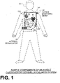
- FIG. 1 depicts components of a WCD system 101 made according to embodiments, as it might be worn by a patient 82.
- a patient such as patient 82 may also be referred to as a person and/or wearer, since that patient wears components of the WCD system.
- a generic support structure 170 is shown relative to the body of patient 82, and thus also relative to his or her heart 85.
- Structure 170 could be a harness, a vest, a half-vest, one or more belts, or a garment, etc., as per the above.
- Structure 170 could be implemented in a single component, or multiple components, and so on.
- Structure 170 is wearable by patient 82, but the manner of wearing it is not depicted, as structure 170 is depicted only generically in FIG. 1 and, in fact, partly conceptually.
- a WCD system is configured to defibrillate a patient who is wearing it, by delivering an electrical charge to the patient's body in the form of an electric shock delivered in one or more pulses.
- FIG. 1 shows a sample external defibrillator 100, and sample defibrillation electrodes 104, 108, which are coupled to external defibrillator 100 via electrode leads 105.
- Defibrillator 100 and defibrillation electrodes 104, 108 are coupled to support structure 170. As such, many of the components of defibrillator 100 can be therefore coupled to support structure 170.
- defibrillator 100 can administer, via electrodes 104, 108, a brief, strong electric pulse 111 through the body.
- Pulse 111 also known as a defibrillation shock or therapy shock, is intended to go through and restart heart 85, in an effort to save the life of patient 82.
- Pulse 111 can further include one or more pacing pulses, and so on.
- a prior art defibrillator typically decides whether to defibrillate or not based on an ECG signal of the patient.
- defibrillator 100 can defibrillate, or not defibrillate, also based on other inputs.
- WCD system 101 includes patient parameter electrodes 114 and 118 coupled to external defibrillator 100 via electrode leads 116.
- Patient parameter electrodes 114 and 118 are shown unsupported by support structure 170. Patient parameter electrodes may alternatively be supported by support structure 170 as appropriate for the patent parameter being monitored. In some embodiments there may be only one patient parameter electrode or more than two patient parameter electrodes, as appropriate for the patient parameter or parameters being monitored. In an embodiment in which the patient parameter electrodes include ECG electrodes, for example, there may be a required number of patient parameter electrodes depending on the configuration being used, such as three, four, five, or ten electrodes, which are distributed appropriately on the patient's body, as is known in the art. Patient parameter electrodes 114 and 118 are therefore intended as representative of a set of electrodes that is appropriate for the parameter or parameters being monitored.
- the WCD system may optionally include an outside monitoring device 180.
- Device 180 is called an "outside" device because it is provided as a standalone device, for example not within the housing of defibrillator 100.
- Device 180 can be configured to sense or monitor at least one local parameter.
- a local parameter can be a parameter of patient 82, or a parameter of the WCD system, or a parameter of the environment, as will be described later in this document.
- Device 180 may include one or more transducers that are configured to render one or more physiological inputs from one or more patient parameters that it senses.
- device 180 is physically coupled to support structure 170.
- device 180 can be communicatively coupled with other components, which are coupled to support structure 170.
- Such communication can be implemented by a communication module, as will be deemed applicable by a person skilled in the art in view of this disclosure.
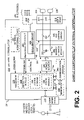
- FIG. 2 is a diagram showing components of an external defibrillator 200, made according to embodiments. These components can be, for example, included in external defibrillator 100 of FIG. 1 .
- the components shown in FIG. 2 can be provided in a housing 201, which is also known as casing 201.
- External defibrillator 200 is intended for a patient who would be wearing it, such as patient 82 of FIG. 1 .
- Defibrillator 200 may further include a user interface 270 for a user 282.
- User 282 can be patient 82, also known as wearer 82.
- user 282 can be a local rescuer at the scene, such as a bystander who might offer assistance, or a trained person.
- user 282 might be a remotely located trained caregiver in communication with WCD system 101.
- User interface 270 can be made in any number of ways.
- User interface 270 may include output devices, which can be visual, audible or tactile, for communicating to a user.
- an output device can be a light, or a screen to display what is sensed, detected and/or measured, and provide visual feedback to rescuer 282 for their resuscitation attempts, and so on.
- Another output device can be a speaker, which can be configured to issue voice prompts, etc. Sounds, images, vibrations, and anything that can be perceived by user 282 can also be called human perceptible indications.
- User interface 270 may also include input devices for receiving inputs from users. Such input devices may additionally include various controls, such as pushbuttons, keyboards, touchscreens, a microphone, and so on.
- An input device can be a cancel switch, which is sometimes called a "live-man" switch. In some embodiments, actuating the cancel switch can prevent the impending delivery of a shock.
- Defibrillator 200 may include an internal monitoring device 281.
- Device 281 is called an "internal” device because it is incorporated within housing 201.
- Monitoring device 281 can sense or monitor patient parameters such as patient physiological parameters, system parameters and/or environmental parameters, all of which can be called patient data.
- patient data can be used on the patient in association with monitoring device 281 (or an external monitoring device such as outside monitoring device 180 of FIG. 1 ), such as electrodes 114 and 118 illustrated in FIG. 1 .
- the associated monitoring device may also have an isolating circuit as discussed below with reference to measurement circuit 220.
- Internal monitoring device 281 can be complementary or an alternative to outside monitoring device 180 of FIG. 1 . Allocating which of the system parameters are to be monitored by which monitoring device can be done according to design considerations.
- Device 281 may include one or more transducers that are configured to render one or more physiological inputs from one or more patient parameters that it senses.
- Patient physiological parameters include, for example, those physiological parameters that can be of any help in detecting by the wearable defibrillation system whether the patient is in need of a shock, plus optionally their medical history and/or event history.
- physiological parameters include the patient's ECG, blood oxygen level, blood flow, blood pressure, blood perfusion, pulsatile change in light transmission or reflection properties of perfused tissue, heart sounds, heart wall motion, breathing sounds and pulse.
- the monitoring device could include a perfusion sensor, a pulse oximeter, a Doppler device for detecting blood flow, a cuff for detecting blood pressure, an optical sensor, illumination detectors and perhaps sources for detecting color change in tissue, a motion sensor, a device that can detect heart wall movement, a sound sensor, a device with a microphone, an SpO2 sensor, and so on.
- Pulse detection is taught at least in Physio-Control's US Patent No. 8,135,462 , which is hereby incorporated by reference in its entirety.
- a person skilled in the art may implement other ways of performing pulse detection.
- the transducer includes an appropriate sensor, and the physiological input is a measurement by the sensor of that patient parameter.
- the appropriate sensor for a heart sound may include a microphone, etc.
- the local parameter is a trend that can be detected in a monitored physiological parameter of patient 82.
- a trend can be detected by comparing values of parameters at different times.
- Parameters whose detected trends can particularly help a cardiac rehabilitation program include: a) cardiac function (e.g. ejection fraction, stroke volume, cardiac output, etc.); b) heart rate variability at rest or during exercise; c) heart rate profile during exercise and measurement of activity vigor, such as from the profile of an accelerometer signal and informed from adaptive rate pacemaker technology; d) heart rate trending; e) perfusion, such as from SpO2 or CO2; f) respiratory function, respiratory rate, etc.; g) motion, level of activity; and so on.
- cardiac function e.g. ejection fraction, stroke volume, cardiac output, etc.
- c) heart rate profile during exercise and measurement of activity vigor such as from the profile of an accelerometer signal and informed from adaptive rate pacemaker technology
- Patient state parameters include recorded aspects of patient 82, such as motion, posture, whether they have spoken recently plus maybe also what they said, and so on, plus optionally the history of these parameters.
- one of these monitoring devices could include a location sensor such as a global positioning system (GPS) location sensor.
- GPS global positioning system
- Such a sensor can detect the location, plus a speed can be detected as a rate of change of location over time.
- Many motion detectors output a motion signal that is indicative of the motion of the detector, and thus of the patient's body. Patient state parameters can be very helpful in narrowing down the determination of whether SCA is indeed taking place.
- a WCD system made according to embodiments may include a motion detector.
- a motion detector can be implemented within monitoring device 180 or monitoring device 281.
- Such a motion detector can be configured to detect a motion event.
- the motion detector may render or generate from the detected motion event a motion detection input that can be received by a subsequent device or functionality.
- a motion event can be defined as is convenient, for example a change in motion from a baseline motion or rest, etc.
- Such a motion detector can be made in many ways as is known in the art, for example by using an accelerometer.
- the patient parameter is a motion
- the transducer includes a motion detector
- the physiological input is a motion measurement.
- System parameters of a WCD system can include system identification, battery status, system date and time, reports of self-testing, records of data entered, records of episodes and intervention, and so on.
- Environmental parameters can include ambient temperature and pressure.
- a humidity sensor may provide information as to whether it is likely raining. Presumed patient location could also be considered an environmental parameter. The patient location could be presumed if monitoring device 180 or 281 includes a GPS location sensor as per the above.
- Defibrillator 200 typically includes a defibrillation port 210, such as a socket in housing 201.
- Defibrillation port 210 includes electrical nodes 214, 218.
- Leads of defibrillation electrodes 204, 208, such as leads 105 of FIG. 1 can be plugged into defibrillation port 210, so as to make electrical contact with nodes 214, 218, respectively.
- defibrillation electrodes 204, 208 are connected continuously to defibrillation port 210, instead. Either way, defibrillation port 210 can be used for guiding, via electrodes, to the wearer the electrical charge that has been stored in energy storage module 250. The electric charge will be the shock for defibrillation, pacing, and so on.
- Defibrillator 200 may optionally also have a patient parameter sense port 219 in housing 201 and configured to be coupled to the patient, such as for plugging in sensing electrodes 209.
- patient parameter port 219 is an ECG port, in which case sensing electrodes 209 are ECG electrodes having ECG leads connecting the electrodes to the port. It is also possible that sensing electrodes 209 can be connected continuously to patient parameter port 219, instead.
- Sensing electrodes 209 are types of transducers that can help sense a patient parameter signal, such as a voltage.
- the sensing port is an ECG port
- sensing electrodes 209 sense an ECG signal, e.g.
- Sensing electrodes 209 can be attached to the inside of support structure 170 for making good electrical contact with the patient, similarly as defibrillation electrodes 204, 208.
- defibrillator 200 also includes a transducer that includes a measurement circuit 220.
- Measurement circuit 220 senses one or more electrical physiological signal of the patient from patient parameter sense port 219.
- the parameter can be an ECG, which can be sensed as a voltage difference between sensing electrodes 209.
- the parameter can be an impedance, which can be sensed between separate sensing electrodes 209 connected to measurement circuit 220 through the connections of patient parameter sense port 219. Sensing the impedance can be useful for detecting, among other things, whether sensing electrodes 209 are not making good electrical contact with the patient's body. These patient physiological signals can be sensed, when available.
- Measurement circuit 220 can then render or generate information about them as physiological inputs, data, other signals, etc. More strictly speaking, the information rendered by measurement circuit 220 is output from it, but this information can be called an input because it is received by a subsequent device or functionality as an input.
- measurement circuit 220 includes an isolating circuit 222 configured to electrically isolate patient parameter sense port 219 from a first circuit ground 224 to which other external defibrillator circuits are connected. Isolating circuit 222 may in turn use a second circuit ground 226 isolated from first circuit ground 224 for circuits electrically coupled to sense port 219. This isolation improves the quality of the acquired ECG data, which may result in fewer false alarms and improved patient safety. This is an improvement over prior art versions that use a common voltage reference, typically referred to as a "ground,” for all parts of the WCD system, which is therefore not isolated.
- Non-isolated ECG acquisition systems are susceptible to environmental noise sources such as 60Hz fields in the vicinity of the WCD system. Patient leakage currents could be difficult to control. Further, electrical noise generated by switch mode power supplies or high voltage charging circuits could couple into the ECG acquisition system of the WCD system.
- Defibrillator 200 also includes a processor 230 connected to first circuit ground 224.
- Processor 230 may be implemented in any number of ways. Such ways include, by way of example and not of limitation, digital and/or analog processors such as microprocessors and digital signal processors (DSPs); controllers such as microcontrollers; software running in a machine; programmable circuits such as field programmable gate arrays (FPGAs), field-programmable analog arrays (FPAAs), programmable logic devices (PLDs), application specific integrated circuits (ASICs), any combination of one or more of these, and so on.
- DSPs digital signal processors
- controllers such as microcontrollers
- software running in a machine programmable circuits such as field programmable gate arrays (FPGAs), field-programmable analog arrays (FPAAs), programmable logic devices (PLDs), application specific integrated circuits (ASICs), any combination of one or more of these, and so on.
- FPGAs field programmable gate
- Processor 230 can be considered to have a number of modules.
- One such module can be a detection module 232.
- Detection module 232 can include a ventricular fibrillation (VF) detector.
- the patient's sensed ECG from measurement circuit 220 which can be available as physiological inputs, data, or other signals, may be used by the VF detector to determine whether the patient is experiencing VF.
- Detecting VF is useful, because VF results in SCA.
- Detection module 232 can also include a (shockable) ventricular tachycardia (VT) detector, and so on.
- VT ventricular tachycardia
- Another such module in processor 230 can be an advice module 234, which generates advice for what to do.
- the advice can be based on outputs of detection module 232.
- the advice is a shock/no shock determination that processor 230 can make, for example via advice module 234.
- the shock/no shock determination can be made by executing a stored Shock Advisory Algorithm.
- a Shock Advisory Algorithm can make a shock/no shock determination from one or more of ECG signals that are captured according to embodiments, and determining whether a shock criterion is met. The determination can be made from a rhythm analysis of the captured ECG signal or otherwise.
- an electrical charge is delivered to the patient. Delivering the electrical charge is also known as discharging. Shocking can be for defibrillation, pacing, and so on.
- Processor 230 can include additional modules, such as other module 236, for other functions.
- additional modules such as other module 236, for other functions.
- internal monitoring device 281 it may be operated in part by processor 230, etc.
- Defibrillator 200 optionally further includes a memory 238, which can work together with processor 230.
- Memory 238 may be implemented in any number of ways. Such ways include, by way of example and not of limitation, volatile memories, nonvolatile memories (NVM), read-only memories (ROM), random access memories (RAM), magnetic disk storage media, optical storage media, smart cards, flash memory devices, any combination of these, and so on. Memory 238 is thus a non-transitory storage medium.
- Memory 238, if provided, can include programs for processor 230, which processor 230 may be able to read and execute. More particularly, the programs can include sets of instructions in the form of code, which processor 230 may be able to execute upon reading.
- Executing is performed by physical manipulations of physical quantities, and may result in functions, processes, actions and/or methods to be performed, and/or the processor to cause other devices or components or blocks to perform such functions, processes, actions and/or methods.
- the programs can be operational for the inherent needs of processor 230, and can also include protocols and ways that decisions can be made by advice module 234.
- memory 238 can store prompts for user 282, if this user is a local rescuer, or the patient.
- memory 238 can store data.
- the data can include patient data, system data and environmental data, for example as learned by internal monitoring device 281 and outside monitoring device 180.
- the data can be stored in memory 238 before it is transmitted out of defibrillator 200, or stored there after it is received by defibrillator 200.
- Defibrillator 200 may also include a power source 240 also connected to first circuit ground 224.
- power source 240 typically includes a battery. Such a battery is typically implemented as a battery pack, which can be rechargeable or not. Sometimes a combination is used of rechargeable and non-rechargeable battery packs.
- Other embodiments of power source 240 can include an energy storage capacitor, and so on.
- power source 240 is controlled by processor 230.
- Defibrillator 200 additionally includes an energy storage module 250 also connected to first circuit ground 224.
- Energy storage module can be coupled to the support structure of the WCD system.
- Module 250 is where some electrical energy is stored in the form of an electrical charge, when preparing it for discharge to administer a shock.
- Module 250 can be charged from power source 240 to the right amount of energy, as controlled by processor 230.
- module 250 includes a capacitor 252, which can be a single capacitor or a system of capacitors, and so on. As described above, capacitor 252 can store the energy in the form of an electrical charge, for delivering to the patient.
- Defibrillator 200 moreover includes a discharge circuit 255.
- processor 230 can be configured to control discharge circuit 255 to discharge through the patient the electrical charge stored in energy storage module 250.
- circuit 255 can permit the energy stored in module 250 to be discharged to nodes 214, 218, and from there also to defibrillation electrodes 204, 208, so as to cause a shock to be delivered to the patient.
- Circuit 255 can include one or more switches 257. Switches 257 can be made in a number of ways, such as by an H-bridge, and so on. Circuit 255 can also be controlled via user interface 270.
- Defibrillator 200 can optionally include a communication module 290, for establishing one or more wireless communication links with other devices of other entities, such as a remote assistance center, Emergency Medical Services (EMS), and so on.
- Module 290 may also include an antenna, portions of a processor, and other sub-components as may be deemed necessary by a person skilled in the art. This way, data and commands can be communicated, such as patient data, event information, therapy attempted, CPR performance, system data, environmental data, and so on.
- Defibrillator 200 can optionally include other components.
- one or more of the components of the shown WCD system have been customized for patient 82.
- This customization may include a number of aspects.
- support structure 170 can be fitted to the body of patient 82.
- baseline physiological parameters of patient 82 can be measured, such as the heart rate of patient 82 while resting, while walking, motion detector outputs while walking, etc.
- Such baseline physiological parameters can be used to customize the WCD system, in order to make its diagnoses more accurate, since bodies behave differently.
- such parameters can be stored in a memory of the WCD system, and so on.
- a programming interface can be made according to embodiments, which receives such measured baseline physiological parameters.
- Such a programming interface may input automatically in the WCD system the baseline physiological parameters, along with other data.
- FIG. 3 illustrates samples of components of a measurement circuit 320.
- Measurement circuit 320 is an embodiment of measurement circuit 220 of FIG. 2 that includes an isolating circuit 322 and an ECG acquisition circuit 328.
- the patient parameter is an electrical patient physiological signal, e.g., an ECG signal, received at an ECG port 319, as an example of patient parameter sense port 219, from Electrocardiogram (ECG) electrodes 309, as an example of patient parameter electrodes 209.
- ECG acquisition circuit 328 is configured to detect the ECG signal.
- ECG acquisition circuit 328 is operatively coupled to the patient parameter sense port (ECG port 319) and isolating circuit 322.
- ECG acquisition circuit 328 operatively couples isolating circuit 322 to ECG port 319, a patient parameter sense port, and correspondingly to ECG electrodes 309.
- ECG acquisition circuit 328 is connected to second circuit ground 326 and is isolated from first circuit ground 324.
- Isolating circuit 322 can be thought of defining an isolation boundary 370, which separates an isolated side from a non-isolated side in the WCD system. As will be seen later in this document, isolation boundary 370 may be implemented by an isolation barrier.
- Measurement circuit 320 has a second circuit ground 326 that is isolated from first circuit ground 324.
- Isolating circuit 322 is configured to electrically isolate first circuit ground 324 from second circuit ground 326, and thereby electrically isolate ECG port 319, as an example of a patient parameter sense port, from first circuit ground 324.
- Processor 330 as an example of processor 230, is electrically connected to first circuit ground 324 and received ECG data from the portion of isolating circuit 322 also connected to first circuit ground 324.
- processor 330 may send one or more control signals to ECG acquisition circuit 328 via isolating circuit 322.
- FIG. 4 is a block diagram of a sample of a measurement circuit of the external defibrillator of FIG. 2 , made according to alternate embodiments.
- Measurement circuit 420 includes an isolating circuit 422 and an ECG acquisition circuit 428.
- an ECG port 419 receives a patient-parameter ECG signal from ECG electrodes 409.
- ECG acquisition circuit 428 is configured to detect the ECG signal.
- Isolating circuit 422 is operatively coupled to ECG port 419 and ECG acquisition circuit 428.
- Isolating circuit 422 operatively couples ECG acquisition circuit 428 to ECG port 419, the patient parameter sense port.
- ECG acquisition circuit 428 is connected to the first circuit ground
- isolating circuit 422 of measurement circuit 420 has a portion connected to first circuit ground 424 and a portion connected to second circuit ground 426, which is isolated from the first circuit ground.
- Isolating circuit 422 is configured to electrically isolate first circuit ground 424 from second circuit ground 426, and thereby electrically isolate ECG port 419, and thereby ECG electrodes 409, from first circuit ground 424.
- Processor 430 as an example of processor 230, is electrically connected to first circuit ground 324 and receives ECG data directly from ECG acquisition circuit 428.
- processor 430 may send one or more control signals to ECG acquisition circuit 428.
- Isolating circuit 422 can be thought of defining an isolation boundary 470, which separates an isolated side from a non-isolated side in the WCD system.
- FIG. 5 is a block diagram of a sample isolating circuit for the measurement circuit of FIG. 3 .
- Isolating circuit 522 includes an isolating signal coupler 510, an optional voltage difference reducing circuit 520, and an isolated power supply 530.
- Isolating circuit 522 includes a non-isolated circuit portion connected to first circuit ground 524, an isolated circuit portion connected to second circuit ground 526, which is isolated from the first circuit ground.
- Isolating circuit 522 includes an isolation barrier 570 electrically isolating the isolated circuit portion from the non-isolated circuit portion.
- Patient parameter sense port 219 such as ECG port 319 or 419, is thereby isolated from first circuit ground 524, preferably with at least 100 volts of protection across the isolation barrier.
- the isolation barrier provides protection from the voltages applied by the defibrillator discharge circuit.
- Isolating signal coupler 510 is configured to couple a signal representative of an ECG signal--the sensed patient parameter--from the isolated circuit portion of isolating circuit 522 to the non-isolated circuit portion of the isolating circuit.
- the signal is a digital signal, such as for isolating circuit 322 of FIG. 3
- isolating signal coupler 510 includes an isolated digital data coupler configured to couple a first digital signal representative of the sensed patient parameter from ECG acquisition circuit 328 to processor 330.
- isolating signal coupler 510 is further configured to couple a second signal, such as a control signal, from processor 330 through the non-isolated circuit portion of isolating circuit 522 and the isolated circuit portion of the isolating circuit to circuits connected to the second circuit ground 526, such as the ECG acquisition circuit.
- a second signal such as a control signal
- signals can be coupled either direction or both directions across isolation barrier 570.
- Isolating signal coupler 510 may be a digital signal coupler or an analog signal coupler. Isolation may be provided by appropriate means, such as galvanic couplers, such as provided by inductance or capacitance devices, such as an isolation transformer or an isolation capacitor, or by a non-electrical means, such as an opto-isolator. Analog signals and some digital signals are converted into a form of alternating current appropriate to cross over the isolation barrier or to cross between other isolated signal transferring components. For example, an analog signal may be converted to a binary signal using an appropriate signal-processing circuit, such as provided by an analog-to-digital converter (ADC), a switching circuit, or a pulse-width modulator. The signal form may then be converted back to its original form or further processed in its digital form, depending on the application.
- ADC analog-to-digital converter
- the non-isolated portion of isolating signal coupler 510 receives power from a non-isolated direct-current (DC) power source NDC.
- the isolated portion of isolating signal coupler 510 receives power from an isolated direct-current (DC) power source IDC.
- Isolated power source IDC is electrically isolated from non-isolated power source NDC.
- Isolated power source IDC may be produced from non-isolated power source NDC, as is provided by isolated power supply 530.
- the two power sources may be entirely independent, each with electrically separate and isolated power sources, such as batteries, and associated power supply circuits.
- Isolating circuit 522 further includes a voltage-difference reducing circuit 520 configured to reduce a voltage difference between the first and second circuit grounds.
- First circuit ground 524 is a common reference for circuits of the defibrillator that are not isolated.
- Second circuit ground not being connected to first circuit ground 524, has a reference level that floats relative to the common reference level of the first circuit ground. The voltage on the second circuit ground can thus vary compared to the first circuit ground.
- Voltage difference reducing circuit 520 provides a protected current path across isolation barrier 570 between the first and second circuit grounds, that does not substantially compromise the isolation between the two circuit grounds. This current path allows the voltages of the first and second circuit grounds to equalize or approach equalization. This maintains the reference potential of the first and second grounds at close to the same level. As such, even with circuit 520, embodiments attain at least substantial isolation. And, without circuit 520, isolation is even more complete.
- Isolated power supply 530 is configured to transfer power from a non-isolated power source, such as power source 240 of defibrillator 200 shown in FIG. 2 , to the isolated circuit portion of isolating circuit 522. Accordingly, when isolating circuit 522 is configured as shown in FIG. 3 , isolated power supply 530 is configured to transfer power from non-isolated power source 240 to isolated ECG acquisition circuit 328.
- Isolated power supply 530 includes a transformer driver 540 connected to non-isolated first circuit ground 524, an isolation transformer 550 having an input side connected to non-isolated circuit ground 524 and an isolated side connected to isolated circuit ground 526, and an isolated rectifier 560 connected to isolated circuit ground 526.
- Isolation transformers use varying current, such as alternating current, to transfer power.
- Transformer driver 540 is a switching circuit that converts the constant DC voltage of non-isolated power source NDC into an alternating power signal that is applied to isolation transformer 550.
- the output alternating power signal of the isolation transformer which is electrically isolated from the input by isolation barrier 570, is then converted to an isolated direct-current power source IDC by rectifier 560.
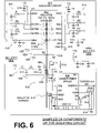
- FIG. 6 is a circuit diagram of a sample of the isolating circuit of FIG. 5 as an embodiment of the measurement circuit of FIG. 3 , made according to embodiments.
- the isolated side is shown at the left, while the non-isolated side is shown to the right, which is flipped compared to FIG.s 3 and 5 .
- isolating circuit 622 is disposed between ECG isolating circuit 328 and processor 330.
- Isolating circuit 622 includes an isolating signal coupler 610 including an integrated-circuit isolated digital data coupler 612 (U1) embodied as an integrated circuit configured to couple a first digital signal representative of the sensed patient parameter from the ECG acquisition circuit to the processor.
- U1 integrated-circuit isolated digital data coupler 612
- the ECG data signal is input into terminal INB4 of isolated digital data coupler 612 and output on terminal OUTA4.
- Isolated digital data coupler 612 is accordingly configured to couple a signal representative of the sensed patient parameter, i.e., the ECG signal, from an isolated circuit portion of isolating circuit 622, shown on the left side of isolation barrier 670 in FIG. 6 , to a non-isolated circuit portion of isolating circuit 622, shown on the right side of the isolation barrier.
- the isolated circuit portion connected to isolated second circuit ground 626, is isolated from first circuit ground 624.
- the non-isolated circuit portion is connected to first circuit ground 624.
- Isolated digital data coupler 612 is further configured to couple three digital control signals from the processor to the ECG acquisition circuit.
- the control signals are input on circuit terminals INA1-3 and output on circuit terminals OUTB1-3.
- the data signals are coupled across isolation barrier 670 by respective isolating capacitors 611.
- Isolating signal coupler 610 includes low-pass RC input filters 614 and output filters 616 that condition the data signals received by and output by the isolated digital data coupler. While the illustrated embodiment includes bidirectional data across the isolation barrier, other embodiments include data only being transferred from the isolated to the non-isolated sides of the isolating circuit.
- Isolated digital data coupler 612 receives power for the non-isolated portion of the circuit from a non-isolated voltage source V N and receives power for the isolated portion of the circuit from an isolated voltage source V I .
- Isolating circuit 622 further includes a voltage-difference reducing circuit 620 extending across isolation barrier 670 and configured to reduce a voltage difference between the isolated and non-isolated circuit grounds.
- voltage-difference reducing circuit 620 includes a resistor R9 connecting non-isolated first circuit ground 624 to isolated second circuit ground 626.
- the value of resistor R9 may be selected to limit the current flowing through it.
- resistor R9 may have a value of 1 gigaohm. The 1-gigaohm resistor across the isolation barrier keeps the non-isolated and isolated grounds at relatively the same voltage but has no or little effect on the operation of the other circuits.
- Isolating circuit 622 further includes an isolated power supply 630 configured to transfer power from the non-isolated power source to the isolated circuit portion of the isolating circuit, and thereby transfer power from the power source to the ECG acquisition circuit.
- Non-isolated power source 240 is used to produce a non-isolated power source V N .
- Isolated power supply 630 produces an isolated voltage source V I and includes an integrated-circuit transformer driver 640 (U2) connected to non-isolated first circuit ground 624.
- Transformer driver 640 is a switching circuit that converts the constant DC voltage of non-isolated power source V N into an alternating power signal that is applied to an isolation transformer 650.
- Isolation transformer 650 includes a first winding 636 coupled to non-isolated first circuit ground 624 and a second winding 638 isolated from the first winding by isolation barrier 670 and coupled to isolated second circuit ground 626.
- An isolated rectifier 660 is connected to transformer second winding 638 and connected to isolated circuit ground 626. Rectifier 660 converts the alternating-current power signal produced on second winding 638 of transformer 650 to an isolated direct-current power source V I .
- the circuit components of isolating circuit 622 have values appropriate for the application. In some embodiments, the components have the following values:
- Capacitors C1-C8 and C14: 10pF; C9, C10, C13, C16, and C19: 0.1 ⁇ F; C11: 47 ⁇ F; C12 and C18: 10 ⁇ F; C15: 1.0 ⁇ F; and C17: 4700pF.
- Resistors R1-R8: 100 ohms; R9: 1G ohms; R10: 8.08k ohms; R11: 18.2k ohms; R12: 8.04k ohms; R13: 120k ohms; R14: 100k ohms; R15: 20.0k ohms; and R16: 43.2k ohms.
- Inductors L1 and L3: inductor no. BLM18EG4718N1D; and L2: 10 ⁇ H.
- an isolation barrier between the patient-parameter ECG port, and also preferably the ECG acquisition circuitry, and the rest of the WCD system may provide advantages over a conventional non-isolated system.
- the ECG system is isolated from the defibrillation circuit with a small capacitance between them. As such, the defibrillation circuitry and non-isolated circuit ground may not cause an imbalance in the ECG acquisition system and have little to no adverse effect on the ECG signal quality.
- This larger capacitance has two effects. It results in more common mode signals being converted to differential signals that degrade the ECG signals. Also, the varying nature of the larger capacitance generates more common mode signals which get converted to differential signals and further degrade the ECG signal.
- Isolating the ECG acquisition system removes the influence of the capacitance between the non-isolated components and earth or components electrically connected to earth from the ECG acquisition system including the ECG acquisition circuit, ECG port, and ECG electrodes.
- the capacitance to earth is limited to the smaller isolated ground system and the earth. This can be made considerably smaller than the complete WCD system ground system. This may result in the ECG signal being degraded significantly less by having a much smaller capacitance between the isolated ground and earth as compared to the non-isolated WCD system.
- the isolating circuitry reduces the coupling between electrical noise sources on the non-isolated side and the ECG acquisition system. This results in higher ECG signal quality.
- the isolated circuits form an isolation zone that includes an isolated power supply and an isolated digital data coupler for transferring information between the isolated ECG acquisition system and the non-isolated parts of the WCD system.
- the non-isolated WCD system generally includes a processor for both controlling the ECG acquisition system and receiving ECG and other data from this system.
- Many of the benefits of the isolated ECG acquisition system may be realized by using an isolation barrier providing an isolation voltage as low as around 100 volts. However, the isolation barrier preferably provides enough isolation to not break down during the defibrillation electrical discharge.
- FIGS. 1 , 2 , 4 , and 5 can include an analog isolating signal coupler that transfers the analog signals from the isolated section to the non-isolated section of the WCD system, which then includes the ECG acquisition circuit.
- the phrases "constructed to” and/or “configured to” denote one or more actual states of construction and/or configuration that is fundamentally tied to physical characteristics of the element or feature preceding these phrases and, as such, reach well beyond merely describing an intended use. Any such elements or features can be implemented in a number of ways, as will be apparent to a person skilled in the art after reviewing the present disclosure, beyond any examples shown in this document.
- a single reference numeral may be used consistently to denote a single item, aspect, component, or process.
- a further effort may have been made in the drafting of this description to use similar though not identical reference numerals to denote other versions or embodiments of an item, aspect, component or process that are identical or at least similar or related. Where made, such a further effort was not required, but was nevertheless made gratuitously so as to accelerate comprehension by the reader. Even where made in this document, such a further effort might not have been made completely consistently for all of the versions or embodiments that are made possible by this description. Accordingly, the description controls in defining an item, aspect, component or process, rather than its reference numeral. Any similarity in reference numerals may be used to infer a similarity in the text, but not to confuse aspects where the text or other context indicates otherwise.
- the term “including” should be interpreted as “including but not limited to,” the term “having” should be interpreted as “having at least,” etc. If a specific number is ascribed to a claim recitation, this number is a minimum but not a maximum unless stated otherwise. For example, where a claim recites “a" component or “an” item, it means that it can have one or more of this component or item.
Landscapes
- Health & Medical Sciences (AREA)
- Radiology & Medical Imaging (AREA)
- Engineering & Computer Science (AREA)
- Biomedical Technology (AREA)
- Nuclear Medicine, Radiotherapy & Molecular Imaging (AREA)
- Life Sciences & Earth Sciences (AREA)
- Animal Behavior & Ethology (AREA)
- General Health & Medical Sciences (AREA)
- Public Health (AREA)
- Veterinary Medicine (AREA)
- Heart & Thoracic Surgery (AREA)
- Cardiology (AREA)
- Electrotherapy Devices (AREA)
Claims (14)
- Tragbares Cardioverter-Defibrillator-System (WCD-System) (101), mit:einer Haltestruktur (170), die dazu eingerichtet ist, von einem Patienten (82) getragen zu werden,einer Energiequelle (240), die mit einer ersten Schaltungsmasse verbunden ist,einem Energiespeichermodul (250), das mit der ersten Schaltungsmasse verbunden und so eingerichtet ist, dass es mit der Haltestruktur gekoppelt ist, von der Energiequelle (240) geladen wird und eine elektrische Ladung speichert,einer Entladeschaltung (255), die mit dem Energiespeichermodul (250) gekoppelt ist,einem Patientenparameterabtastanschluss (219; 319; 419), der zur Kopplung mit dem Patienten (82) eingerichtet ist,einem Messkreis (220; 320; 420), der so eingerichtet ist, dass er einen physiologischen Eingang von dem Patientenparameterabtastanschluss (219; 319; 419) wiedergibt, wobei der Messkreis eine Trennschaltung aufweist, die so eingerichtet ist, dass sie den Patientenparameterabtastanschluss galvanisch von der ersten Schaltungsmasse trennt, undeinem Prozessor (230; 330; 430), der mit einer ersten Schaltungsmasse (224; 324; 424; 524; 524) verbunden, mit dem Messkreis (220; 320; 420) wirkungsmäßig gekoppelt und so eingerichtet ist, dass er:aus dem physiologischen Eingang bestimmt, ob ein Schockkriterium erfüllt ist oder nicht, unddie Entladeschaltung (255) so ansteuert, dass sie die elektrische Ladung durch den Patienten (82) entlädt, wenn das Schockkriterium erfüllt ist,dadurch gekennzeichnet, dass die Energiequelle (240) und das Energiespeichermodul (250) mit einer ersten Schaltungsmasse (224; 324; 424; 524; 624) verbunden sind und dass der Messkreis (220; 320; 420) eine Trennschaltung (222, 322; 422; 522; 622) aufweist, die so eingerichtet ist, dass sie den Patientenparameterabtastanschluss (219; 319; 419) galvanisch von der ersten Schaltungsmasse (224; 324; 424; 524; 624) trennt, wobei die Trennschaltung (522; 622) einen getrennten Schaltkreisabschnitt, der mit einer zweiten Schaltungsmasse (526; 626) verbunden ist, die von der ersten Schaltungsmasse (524; 626) getrennt ist, und einen nicht getrennten Schaltkreisabschnitt aufweist, der mit der ersten Schaltungsmasse (524; 624) verbunden ist, und die Trennschaltung (522; 622) ferner eine Spannungsdifferenzreduzierschaltung (620) zwischen der ersten und der zweiten Schaltungsmasse (524, 626) aufweist.
- WCD-System nach Anspruch 1, bei demder Patientenparameter ein elektrisches physiologisches Patientensignal vom Patientenparameterabtastanschluss (219; 319; 419) von Elektrokardiogrammelektroden (EKG-Elektroden) (209; 309; 409) ist undder physiologische Eingang ein EKG-Signal von den EKG-Elektroden (209; 309; 409) enthält.
- WCD-System nach Anspruch 2, bei dem
der Messkreis (320; 420) ferner eine EKG-Erfassungsschaltung (328; 428) aufweist, die wirkungsmäßig mit dem Patientenparameterabtastanschluss (319; 419) und der Trennschaltung (322; 422) gekoppelt ist, wobei die EKG-Erfassungsschaltung (328; 428) zur Erfassung des EKG-Signals eingerichtet ist, wobei der Messkreis (320; 420) eine zweite Schaltungsmasse (226; 326; 426; 526; 626) aufweist, die von der ersten Schaltungsmasse (224; 324; 424; 524; 624) getrennt ist. - WCD-System nach Anspruch 3, bei dem
die Trennschaltung (622) einen getrennten Digitaldatenkoppler (612) aufweist, der so eingerichtet ist, dass er ein erstes digitales Signal, das für den Patientenparameter von der EKG-Erfassungsschaltung (328; 428) bezeichnend ist, mit dem Prozessor (330; 430) koppelt. - WCD-System nach Anspruch 4, bei dem
der getrennte Digitaldatenkoppler (612) so eingerichtet ist, dass er ein zweites digitales Signal vom Prozessor (330; 430) mit der EKG-Erfassungsschaltung (328; 428) koppelt. - WCD-System nach Anspruch 4 oder 5, bei dem die Trennschaltung (622) ferner eine getrennte Energieversorgung (630) aufweist, die zur Übertragung von Energie von der Energiequelle (240) zur EKG-Erfassungsschaltung (328; 428) eingerichtet ist.
- WCD-System nach einem der Ansprüche 3 bis 6, bei dem die Trennschaltung (522) einen Trennsignalkoppler (510) aufweist, der so eingerichtet ist, dass er ein erstes Parametersignal, das für den Patientenparameter vom Patientenparameterabtastanschluss (219; 319; 419) bezeichnend ist, mit der EKG-Erfassungsschaltung (328; 428) koppelt.
- WCD-System nach einem der Ansprüche 2 bis 7, bei dem
die EKG-Erfassungsschaltung (328; 428) die Trennschaltung (322; 422; 522; 622) wirkungsmäßig mit dem Patientenparameterabtastanschluss (219; 319; 419) koppelt und die EKG-Erfassungsschaltung (328; 428) mit einer zweiten Schaltungsmasse (326; 426; 526; 626) verbunden ist, die von der ersten Schaltungsmasse (324; 424; 524; 624) getrennt ist. - WCD-System nach einem der Ansprüche 2 bis 8, bei dem
die Trennschaltung (322; 422) die EKG-Erfassungsschaltung (328; 428) wirkungsmäßig mit dem Patientenparameterabtastanschluss (319; 419) koppelt und die EKG-Erfassungsschaltung (328; 428) mit der ersten Schaltungsmasse (324; 326) verbunden ist. - WCD-System nach einem der vorhergehenden Ansprüche, bei dem
die Trennschaltung (522) eine Trennwand (570) aufweist, die den Patientenparameterabtastanschluss (219; 319; 419) mit einer Absicherung von wenigstens 100 Volt an der Trennwand (570) galvanisch von der ersten Schaltungsmasse (224; 324; 424; 524) trennt. - WCD-System nach einem der vorhergehenden Ansprüche, bei dem
die Spannungsdifferenzreduzierschaltung (620) einen Widerstand aufweist, der die erste Schaltungsmasse (624) mit der zweiten Schaltungsmasse (626) verbindet. - WCD-System nach einem der vorhergehenden Ansprüche, bei dem
die Trennschaltung (622) einen Trennsignalkoppler (610) aufweist, der so eingerichtet ist, dass er ein Signal, das für den Patientenparameter bezeichnend ist, von einem getrennten Schaltkreisabschnitt der Trennschaltung (622) an einen nicht getrennten Schaltkreisabschnitt der Trennschaltung (622) koppelt, wobei der getrennte Schaltkreisabschnitt von der ersten Schaltungsmasse (624) getrennt ist und der nicht getrennte Schaltkreisabschnitt mit der ersten Schaltungsmasse (624) verbunden ist. - WCD-System nach einem der vorhergehenden Ansprüche, bei dem
die Trennschaltung (622) ferner eine getrennte Energieversorgung (630) aufweist, die zur Übertragung von Energie von der Energiequelle (240) zum getrennten Schaltkreisabschnitt der Trennschaltung (622) eingerichtet ist. - WCD-System nach Anspruch 13, bei dem
die getrennte Energieversorgung (630) einen Trenntransformator (650) aufweist, der mit einer ersten Wicklung an die erste Schaltungsmasse (624) gekoppelt ist und mit einer von der ersten Wicklung getrennten zweiten Wicklung an die zweite Schaltungsmasse (626) gekoppelt ist.
Applications Claiming Priority (2)
| Application Number | Priority Date | Filing Date | Title |
|---|---|---|---|
| US201562263566P | 2015-12-04 | 2015-12-04 | |
| US15/365,801 US10322291B2 (en) | 2015-12-04 | 2016-11-30 | Wearable cardioverter defibrillator (WCD) system with isolated patient parameter component |
Publications (2)
| Publication Number | Publication Date |
|---|---|
| EP3175883A1 EP3175883A1 (de) | 2017-06-07 |
| EP3175883B1 true EP3175883B1 (de) | 2022-08-24 |
Family
ID=57471771
Family Applications (1)
| Application Number | Title | Priority Date | Filing Date |
|---|---|---|---|
| EP16202067.1A Active EP3175883B1 (de) | 2015-12-04 | 2016-12-02 | Am körper tragbares kardioverter-defibrillator-system mit einem messkreis umfassend einen isolierkreis |
Country Status (2)
| Country | Link |
|---|---|
| US (2) | US10322291B2 (de) |
| EP (1) | EP3175883B1 (de) |
Families Citing this family (21)
| Publication number | Priority date | Publication date | Assignee | Title |
|---|---|---|---|---|
| CN113559415B (zh) | 2015-08-26 | 2024-06-21 | 元素科学公司 | 可穿戴体外除颤器 |
| US10322291B2 (en) * | 2015-12-04 | 2019-06-18 | West Affum Holdings Corp. | Wearable cardioverter defibrillator (WCD) system with isolated patient parameter component |
| RU2703640C1 (ru) * | 2016-01-11 | 2019-10-21 | Конинклейке Филипс Н.В. | Способ и устройство для незвукового считывания индикатора состояния дефибриллятора |
| US11077310B1 (en) | 2016-10-04 | 2021-08-03 | West Affum Holdings Corp. | Wearable cardioverter defibrillator (WCD) system detecting QRS complexes in ECG signal by matched difference filter |
| US11471693B1 (en) | 2018-02-14 | 2022-10-18 | West Affum Holdings Dac | Wearable cardioverter defibrillator (WCD) system choosing to consider ECG signals from different channels per QRS complex widths of the ECG signals |
| US11160990B1 (en) | 2018-02-14 | 2021-11-02 | West Affum Holdings Corp. | Wearable cardioverter defibrillator (WCD) alarms |
| US11865354B1 (en) | 2018-02-14 | 2024-01-09 | West Affum Holdings Dac | Methods and systems for distinguishing VT from VF |
| US12179032B2 (en) | 2018-02-14 | 2024-12-31 | West Affum Holdings Dac | Wearable cardioverter defibrillator (WCD) segment based episode opening and confirmation periods |
| EP3546957A1 (de) * | 2018-03-28 | 2019-10-02 | Siemens Healthcare GmbH | Isolierter erdungseffektivitätsmonitor |
| US11247041B2 (en) | 2018-08-10 | 2022-02-15 | West Affum Holdings Corp. | Wearable cardioverter defibrillator (WCD) with ECG preamp having active input capacitance balancing |
| EP3863511B1 (de) | 2018-10-10 | 2024-10-09 | Element Science, Inc. | Am körper tragbares medizinprodukt mit einweg- und mehrwegkomponenten |
| US11334826B2 (en) * | 2019-01-18 | 2022-05-17 | West Affum Holdings Corp. | WCD system prioritization of alerts based on severity and/or required timeliness of user response |
| US11191971B2 (en) * | 2019-03-07 | 2021-12-07 | West Affum Holdings Corp. | Wearable cardioverter defibrillator (WCD) system with active ECG cable shielding |
| US11412973B2 (en) | 2019-06-28 | 2022-08-16 | Zoll Medical Corporation | Modular garment for a wearable medical device |
| US11571159B1 (en) * | 2020-07-23 | 2023-02-07 | Meta Platforms Technologies, Llc | Floating biopotential samplings |
| US11819704B2 (en) * | 2020-08-21 | 2023-11-21 | West Affum Holdings Dac | Positive system alerts |
| US12569696B2 (en) | 2022-03-03 | 2026-03-10 | West Affum Holdings Dac | Wearable medical system (WMS) implementing wearable cardioverter defibrillator (WCD) capturing, recording and reporting ambient sounds |
| US12220592B1 (en) | 2023-01-18 | 2025-02-11 | Bardy Technologies, Inc. | Defibrillator case |
| US12168137B1 (en) | 2023-01-18 | 2024-12-17 | Bardy Technologies, Inc. | De-energizable defibrillation assembly |
| US12280265B1 (en) * | 2024-08-15 | 2025-04-22 | Bardy Technologies, Inc. | Solid state defibrillation therapy generator |
| US12383728B1 (en) | 2024-08-15 | 2025-08-12 | Bardy Technologies, Inc. | Circuit for defibrillation waveform generation |
Family Cites Families (82)
| Publication number | Priority date | Publication date | Assignee | Title |
|---|---|---|---|---|
| DE2029044C3 (de) | 1970-06-12 | 1974-02-21 | Agfa-Gevaert Ag, 5090 Leverkusen | Fotografische Entwicklungsvorrichtung |
| US4619265A (en) | 1984-03-08 | 1986-10-28 | Physio-Control Corporation | Interactive portable defibrillator including ECG detection circuit |
| US4583524A (en) | 1984-11-21 | 1986-04-22 | Hutchins Donald C | Cardiopulmonary resuscitation prompting |
| US5078134A (en) | 1988-04-25 | 1992-01-07 | Lifecor, Inc. | Portable device for sensing cardiac function and automatically delivering electrical therapy |
| US4928690A (en) | 1988-04-25 | 1990-05-29 | Lifecor, Inc. | Portable device for sensing cardiac function and automatically delivering electrical therapy |
| US4955381A (en) | 1988-08-26 | 1990-09-11 | Cardiotronics, Inc. | Multi-pad, multi-function electrode |
| JPH05507003A (ja) | 1990-04-02 | 1993-10-14 | ケイ.ジェイ.メレット ノミニーズ ピーティーワイ.エルティディ | 心肺蘇生(cpr)の誘導装置 |
| US5228449A (en) | 1991-01-22 | 1993-07-20 | Athanasios G. Christ | System and method for detecting out-of-hospital cardiac emergencies and summoning emergency assistance |
| US5405362A (en) | 1991-04-29 | 1995-04-11 | The Board Of Regents For The University Of Texas System | Interactive external defibrillation and drug injection system |
| US5353793A (en) | 1991-11-25 | 1994-10-11 | Oishi-Kogyo Company | Sensor apparatus |
| US5491651A (en) | 1992-05-15 | 1996-02-13 | Key, Idea Development | Flexible wearable computer |
| US5474574A (en) | 1992-06-24 | 1995-12-12 | Cardiac Science, Inc. | Automatic external cardioverter/defibrillator |
| US5593426A (en) | 1994-12-07 | 1997-01-14 | Heartstream, Inc. | Defibrillator system using multiple external defibrillators and a communications network |
| US5611815A (en) | 1994-12-08 | 1997-03-18 | Heartstream, Inc. | Defibrillator with training features |
| JP4151766B2 (ja) | 1995-03-03 | 2008-09-17 | コーニンクレッカ フィリップス エレクトロニクス エヌ ヴィ | 差動信号検出器において同相モード信号を用いてアーティファクトを検出する方法および装置 |
| US6319011B1 (en) | 1995-04-06 | 2001-11-20 | Michael J. Motti | Automatic training defibrillator simulator and method |
| US5554174A (en) | 1995-10-18 | 1996-09-10 | Pacesetter, Inc. | System and method for automatically adjusting cardioverter and defibrillator shock energy as a function of time-to-therapy |
| US5792204A (en) | 1996-05-08 | 1998-08-11 | Pacesetter, Inc. | Methods and apparatus for controlling an implantable device programmer using voice commands |
| US5913685A (en) | 1996-06-24 | 1999-06-22 | Hutchins; Donald C. | CPR computer aiding |
| JP3933698B2 (ja) | 1996-07-11 | 2007-06-20 | 株式会社セガ | 音声認識装置、音声認識方法及びこれを用いたゲーム機 |
| US6148233A (en) | 1997-03-07 | 2000-11-14 | Cardiac Science, Inc. | Defibrillation system having segmented electrodes |
| IL131592A0 (en) | 1997-03-17 | 2001-01-28 | Non Invasive Systems Inc | Physiologic signs feedback system |
| DE69829358T2 (de) | 1997-11-06 | 2006-04-06 | Koninklijke Philips Electronics N.V. | Externer defibrillator mit cpr-anzeigen und mit acls-anzeigen |
| US5944669A (en) | 1997-11-20 | 1999-08-31 | Lifecor, Inc. | Apparatus and method for sensing cardiac function |
| US6065154A (en) | 1998-04-07 | 2000-05-23 | Lifecor, Inc. | Support garments for patient-worn energy delivery apparatus |
| US6263238B1 (en) | 1998-04-16 | 2001-07-17 | Survivalink Corporation | Automatic external defibrillator having a ventricular fibrillation detector |
| US6334070B1 (en) | 1998-11-20 | 2001-12-25 | Medtronic Physio-Control Manufacturing Corp. | Visual and aural user interface for an automated external defibrillator |
| US6201992B1 (en) | 1999-04-01 | 2001-03-13 | Agilent Technologies, Inc. | Defibrillator interface capable of generating video images |
| US6287328B1 (en) | 1999-04-08 | 2001-09-11 | Agilent Technologies, Inc. | Multivariable artifact assessment |
| US6681003B2 (en) | 1999-10-05 | 2004-01-20 | Lifecor, Inc. | Data collection and system management for patient-worn medical devices |
| US6762917B1 (en) | 2001-06-12 | 2004-07-13 | Novx Corporation | Method of monitoring ESC levels and protective devices utilizing the method |
| US6437083B1 (en) | 2001-12-06 | 2002-08-20 | General Electric Company | Process for preparing branched aromatic polycarbonates |
| US20080146925A1 (en) | 2006-12-14 | 2008-06-19 | Ep Medsystems, Inc. | Integrated Electrophysiology and Ultrasound Imaging System |
| US20030158593A1 (en) | 2002-02-19 | 2003-08-21 | Heilman Marlin S. | Cardiac garment |
| US7065401B2 (en) | 2002-05-08 | 2006-06-20 | Michael Worden | Method of applying electrical signals to a patient and automatic wearable external defibrillator |
| GB0210889D0 (en) | 2002-05-14 | 2002-06-19 | Koninkl Philips Electronics Nv | Garment and method for producing the same |
| US20040116969A1 (en) | 2002-08-26 | 2004-06-17 | Owen James M. | Pulse detection using patient physiological signals |
| US7162298B2 (en) | 2002-09-10 | 2007-01-09 | Uab Research Foundation | Devices for detecting the presence of cardiac activity following administration of defibrillation therapy |
| US7559902B2 (en) | 2003-08-22 | 2009-07-14 | Foster-Miller, Inc. | Physiological monitoring garment |
| US20050107833A1 (en) | 2003-11-13 | 2005-05-19 | Freeman Gary A. | Multi-path transthoracic defibrillation and cardioversion |
| EP1796789A1 (de) | 2004-09-29 | 2007-06-20 | Koninklijke Philips Electronics N.V. | Hochspannungsmodul für einen externen defibrillator |
| BRPI0718525B1 (pt) | 2006-11-10 | 2019-01-29 | Koninklijke Philips N.V. | sistema para gerar sinais de saída indicativos da qualidade de contato de diversos eletrodos, e método para determinar qualidade de contato de diversos eletrodos |
| US8369944B2 (en) | 2007-06-06 | 2013-02-05 | Zoll Medical Corporation | Wearable defibrillator with audio input/output |
| US7974689B2 (en) | 2007-06-13 | 2011-07-05 | Zoll Medical Corporation | Wearable medical treatment device with motion/position detection |
| US8140154B2 (en) | 2007-06-13 | 2012-03-20 | Zoll Medical Corporation | Wearable medical treatment device |
| US20090005827A1 (en) | 2007-06-26 | 2009-01-01 | David Weintraub | Wearable defibrillator |
| US8498698B2 (en) * | 2008-10-31 | 2013-07-30 | Medtronic, Inc. | Isolation of sensing and stimulation circuitry |
| US8781576B2 (en) | 2009-03-17 | 2014-07-15 | Cardiothrive, Inc. | Device and method for reducing patient transthoracic impedance for the purpose of delivering a therapeutic current |
| US8615295B2 (en) | 2009-03-17 | 2013-12-24 | Cardiothrive, Inc. | External defibrillator |
| WO2011146482A1 (en) | 2010-05-18 | 2011-11-24 | Zoll Medical Corporation | Wearable ambulatory medical device with multiple sensing electrodes |
| JP5986991B2 (ja) | 2010-05-18 | 2016-09-06 | ゾール メディカル コーポレイションZOLL Medical Corporation | 着用可能な治療装置 |
| US8904214B2 (en) | 2010-07-09 | 2014-12-02 | Zoll Medical Corporation | System and method for conserving power in a medical device |
| US8548557B2 (en) | 2010-08-12 | 2013-10-01 | Covidien Lp | Medical electrodes |
| US9937355B2 (en) | 2010-11-08 | 2018-04-10 | Zoll Medical Corporation | Remote medical device alarm |
| US20120144551A1 (en) | 2010-12-09 | 2012-06-14 | Eric Guldalian | Conductive Garment |
| WO2012078857A2 (en) | 2010-12-09 | 2012-06-14 | Zoll Medical Corporation | Electrode with redundant impedance reduction |
| US9427564B2 (en) | 2010-12-16 | 2016-08-30 | Zoll Medical Corporation | Water resistant wearable medical device |
| US8897860B2 (en) | 2011-03-25 | 2014-11-25 | Zoll Medical Corporation | Selection of optimal channel for rate determination |
| EP4152340A1 (de) | 2011-03-25 | 2023-03-22 | Zoll Medical Corporation | System und verfahren zur anpassung von alarmen bei einer tragbaren medizinischen vorrichtung |
| US20120265265A1 (en) | 2011-04-13 | 2012-10-18 | Mehdi Razavi | Automated External Defibrillator Pad System |
| WO2012151160A1 (en) | 2011-05-02 | 2012-11-08 | Zoll Medical Corporation | Patient-worn energy delivery apparatus and techniques for sizing same |
| EP3470830A1 (de) | 2011-09-01 | 2019-04-17 | MC10 Inc. | Elektronik zur erfassung des zustandes von gewebe |
| CN105661695A (zh) | 2011-09-01 | 2016-06-15 | 佐尔医药公司 | 穿戴式监护和治疗设备 |
| IL319973A (en) | 2011-12-20 | 2025-05-01 | Sensible Medical Innovations Ltd | Chest garment for placement of electromagnetic transducers and methods for using chest garment |
| JP2015510780A (ja) | 2012-03-02 | 2015-04-13 | ゾール メディカル コーポレイションZOLL Medical Corporation | 着用式医療監視および/または処置装置を構成するためのシステムおよび方法 |
| WO2013155503A1 (en) | 2012-04-13 | 2013-10-17 | Langer Alois A | Outpatient health emergency warning system |
| US20130317852A1 (en) | 2012-05-22 | 2013-11-28 | Geneva Healthcare, LLC | Medical device information portal |
| CN104870050A (zh) | 2012-05-31 | 2015-08-26 | 佐尔医药公司 | 带有体外起搏的医疗监控和治疗设备 |
| US20140025131A1 (en) | 2012-07-20 | 2014-01-23 | Physio-Control, Inc. | Wearable defibrillator with voice prompts and voice recognition |
| CN104768455B (zh) | 2012-09-11 | 2018-01-02 | L.I.F.E.公司 | 可穿戴式通信平台 |
| US9320884B2 (en) | 2012-12-11 | 2016-04-26 | Nexus Control Systems, Llc | Method and system for switching shock vectors and decreasing transthoracic impedance for cardioversion and defibrillation |
| US9592403B2 (en) | 2013-02-25 | 2017-03-14 | West Affum Holdings Corp. | Wearable cardioverter defibrillator (WCD) system making shock/no shock determinations from multiple patient parameters |
| US20150328472A1 (en) | 2014-05-13 | 2015-11-19 | Physio-Control, Inc. | Wearable cardioverter defibrillator components discarding ecg signals prior to making shock/no shock determination |
| US9757579B2 (en) | 2013-02-25 | 2017-09-12 | West Affum Holdings Corp. | Wearable cardioverter defibrillator (WCD) system informing patient that it is validating just-detected cardiac arrhythmia |
| US9089685B2 (en) | 2013-02-25 | 2015-07-28 | West Affum Holdings Corp. | Wearable defibrillator with a multivector shock waveform |
| US8880196B2 (en) | 2013-03-04 | 2014-11-04 | Zoll Medical Corporation | Flexible therapy electrode |
| ES2894750T3 (es) | 2013-06-28 | 2022-02-15 | Zoll Medical Corp | Sistemas de administración de terapia mediante el uso de un dispositivo médico ambulatorio |
| US20150037636A1 (en) | 2013-08-01 | 2015-02-05 | Zoll Medical Corporation | Mechanical Aspects of a Battery Pack for a Medical Therapy Device |
| CN103405851A (zh) | 2013-08-05 | 2013-11-27 | 郑巍 | 可穿戴式除颤器 |
| CN106456984B (zh) | 2014-02-24 | 2019-07-09 | 元素科学公司 | 体外除颤器 |
| US12191030B2 (en) | 2014-07-07 | 2025-01-07 | Zoll Medical Corporation | Medical device with natural language processor |
| US10322291B2 (en) * | 2015-12-04 | 2019-06-18 | West Affum Holdings Corp. | Wearable cardioverter defibrillator (WCD) system with isolated patient parameter component |
-
2016
- 2016-11-30 US US15/365,801 patent/US10322291B2/en active Active
- 2016-12-02 EP EP16202067.1A patent/EP3175883B1/de active Active
-
2019
- 2019-06-16 US US16/442,523 patent/US11000692B2/en active Active
Also Published As
| Publication number | Publication date |
|---|---|
| EP3175883A1 (de) | 2017-06-07 |
| US20170157416A1 (en) | 2017-06-08 |
| US20190366111A1 (en) | 2019-12-05 |
| US10322291B2 (en) | 2019-06-18 |
| US11000692B2 (en) | 2021-05-11 |
Similar Documents
| Publication | Publication Date | Title |
|---|---|---|
| US11000692B2 (en) | Wearable cardioverter defibrillator (WCD) system with isolated patient parameter component | |
| US20240350817A1 (en) | Wearable cardioverter defibrillator (wcd) system reacting to high-frequency ecg noise | |
| US11944835B2 (en) | Wearable cardioverter defibrillator (WCD) system having WCD mode and also AED mode | |
| US9757581B2 (en) | Wearable cardioverter defibrillator components making aggregate shock/no shock determination from two or more ECG signals | |
| US12569695B2 (en) | Wearable cardioverter defibrillator with a non-invasive blood pressure monitor | |
| US20190076666A1 (en) | Wearable cardioverter defibrillator (wcd) system warning ambulatory patient by weak alerting shock | |
| US11648411B2 (en) | Defibrillation waveforms for a wearable cardiac defibrillator | |
| US9789327B2 (en) | Wearable cardiac defibrillator receiving inputs by being deliberately tapped and methods | |
| US20160331986A1 (en) | Wearable cardiac defibrillator system with communicating battery charger | |
| US12128244B2 (en) | Wearable cardioverter defibrillator (WCD) system with active ECG cable shielding | |
| US10960220B2 (en) | Wearable cardioverter defibrillator (WCD) system evaluating its ECG signals for noise according to tall peak counts | |
| CN107029355B (zh) | 具有隔离患者参数元件的可穿戴式心律转复除颤器(wcd)系统 | |
| US20240165418A1 (en) | Charging and specifying a capacitor for storing charge in a wearable cardiac defibrillator (wcd) | |
| US12300368B1 (en) | Analysis and presentation of aggregated patient and device data within a system that includes a medical device | |
| US11058885B2 (en) | Wearable cardioverter defibrillator (WCD) system detecting ventricular tachycardia and/or ventricular fibrillation using variable heart rate decision threshold |
Legal Events
| Date | Code | Title | Description |
|---|---|---|---|
| AK | Designated contracting states |
Kind code of ref document: A1 Designated state(s): AL AT BE BG CH CY CZ DE DK EE ES FI FR GB GR HR HU IE IS IT LI LT LU LV MC MK MT NL NO PL PT RO RS SE SI SK SM TR |
|
| AX | Request for extension of the european patent |
Extension state: BA ME |
|
| PUAI | Public reference made under article 153(3) epc to a published international application that has entered the european phase |
Free format text: ORIGINAL CODE: 0009012 |
|
| STAA | Information on the status of an ep patent application or granted ep patent |
Free format text: STATUS: THE APPLICATION HAS BEEN PUBLISHED |
|
| STAA | Information on the status of an ep patent application or granted ep patent |
Free format text: STATUS: REQUEST FOR EXAMINATION WAS MADE |
|
| 17P | Request for examination filed |
Effective date: 20171123 |
|
| RBV | Designated contracting states (corrected) |
Designated state(s): AL AT BE BG CH CY CZ DE DK EE ES FI FR GB GR HR HU IE IS IT LI LT LU LV MC MK MT NL NO PL PT RO RS SE SI SK SM TR |
|
| STAA | Information on the status of an ep patent application or granted ep patent |
Free format text: STATUS: EXAMINATION IS IN PROGRESS |
|
| 17Q | First examination report despatched |
Effective date: 20200203 |
|
| GRAP | Despatch of communication of intention to grant a patent |
Free format text: ORIGINAL CODE: EPIDOSNIGR1 |
|
| STAA | Information on the status of an ep patent application or granted ep patent |
Free format text: STATUS: GRANT OF PATENT IS INTENDED |
|
| INTG | Intention to grant announced |
Effective date: 20220321 |
|
| GRAS | Grant fee paid |
Free format text: ORIGINAL CODE: EPIDOSNIGR3 |
|
| GRAA | (expected) grant |
Free format text: ORIGINAL CODE: 0009210 |
|
| STAA | Information on the status of an ep patent application or granted ep patent |
Free format text: STATUS: THE PATENT HAS BEEN GRANTED |
|
| RAP1 | Party data changed (applicant data changed or rights of an application transferred) |
Owner name: WEST AFFUM HOLDINGS DAC |
|
| AK | Designated contracting states |
Kind code of ref document: B1 Designated state(s): AL AT BE BG CH CY CZ DE DK EE ES FI FR GB GR HR HU IE IS IT LI LT LU LV MC MK MT NL NO PL PT RO RS SE SI SK SM TR |
|
| REG | Reference to a national code |
Ref country code: CH Ref legal event code: EP |
|
| REG | Reference to a national code |
Ref country code: IE Ref legal event code: FG4D |
|
| REG | Reference to a national code |
Ref country code: AT Ref legal event code: REF Ref document number: 1513219 Country of ref document: AT Kind code of ref document: T Effective date: 20220915 Ref country code: DE Ref legal event code: R096 Ref document number: 602016074458 Country of ref document: DE |
|
| REG | Reference to a national code |
Ref country code: NL Ref legal event code: FP |
|
| REG | Reference to a national code |
Ref country code: LT Ref legal event code: MG9D |
|
| PG25 | Lapsed in a contracting state [announced via postgrant information from national office to epo] |
Ref country code: SE Free format text: LAPSE BECAUSE OF FAILURE TO SUBMIT A TRANSLATION OF THE DESCRIPTION OR TO PAY THE FEE WITHIN THE PRESCRIBED TIME-LIMIT Effective date: 20220824 Ref country code: RS Free format text: LAPSE BECAUSE OF FAILURE TO SUBMIT A TRANSLATION OF THE DESCRIPTION OR TO PAY THE FEE WITHIN THE PRESCRIBED TIME-LIMIT Effective date: 20220824 Ref country code: PT Free format text: LAPSE BECAUSE OF FAILURE TO SUBMIT A TRANSLATION OF THE DESCRIPTION OR TO PAY THE FEE WITHIN THE PRESCRIBED TIME-LIMIT Effective date: 20221226 Ref country code: NO Free format text: LAPSE BECAUSE OF FAILURE TO SUBMIT A TRANSLATION OF THE DESCRIPTION OR TO PAY THE FEE WITHIN THE PRESCRIBED TIME-LIMIT Effective date: 20221124 Ref country code: LV Free format text: LAPSE BECAUSE OF FAILURE TO SUBMIT A TRANSLATION OF THE DESCRIPTION OR TO PAY THE FEE WITHIN THE PRESCRIBED TIME-LIMIT Effective date: 20220824 Ref country code: LT Free format text: LAPSE BECAUSE OF FAILURE TO SUBMIT A TRANSLATION OF THE DESCRIPTION OR TO PAY THE FEE WITHIN THE PRESCRIBED TIME-LIMIT Effective date: 20220824 Ref country code: FI Free format text: LAPSE BECAUSE OF FAILURE TO SUBMIT A TRANSLATION OF THE DESCRIPTION OR TO PAY THE FEE WITHIN THE PRESCRIBED TIME-LIMIT Effective date: 20220824 |
|
| REG | Reference to a national code |
Ref country code: AT Ref legal event code: MK05 Ref document number: 1513219 Country of ref document: AT Kind code of ref document: T Effective date: 20220824 |
|
| PG25 | Lapsed in a contracting state [announced via postgrant information from national office to epo] |
Ref country code: PL Free format text: LAPSE BECAUSE OF FAILURE TO SUBMIT A TRANSLATION OF THE DESCRIPTION OR TO PAY THE FEE WITHIN THE PRESCRIBED TIME-LIMIT Effective date: 20220824 Ref country code: IS Free format text: LAPSE BECAUSE OF FAILURE TO SUBMIT A TRANSLATION OF THE DESCRIPTION OR TO PAY THE FEE WITHIN THE PRESCRIBED TIME-LIMIT Effective date: 20221224 Ref country code: HR Free format text: LAPSE BECAUSE OF FAILURE TO SUBMIT A TRANSLATION OF THE DESCRIPTION OR TO PAY THE FEE WITHIN THE PRESCRIBED TIME-LIMIT Effective date: 20220824 Ref country code: GR Free format text: LAPSE BECAUSE OF FAILURE TO SUBMIT A TRANSLATION OF THE DESCRIPTION OR TO PAY THE FEE WITHIN THE PRESCRIBED TIME-LIMIT Effective date: 20221125 |
|
| PG25 | Lapsed in a contracting state [announced via postgrant information from national office to epo] |
Ref country code: SM Free format text: LAPSE BECAUSE OF FAILURE TO SUBMIT A TRANSLATION OF THE DESCRIPTION OR TO PAY THE FEE WITHIN THE PRESCRIBED TIME-LIMIT Effective date: 20220824 Ref country code: RO Free format text: LAPSE BECAUSE OF FAILURE TO SUBMIT A TRANSLATION OF THE DESCRIPTION OR TO PAY THE FEE WITHIN THE PRESCRIBED TIME-LIMIT Effective date: 20220824 Ref country code: ES Free format text: LAPSE BECAUSE OF FAILURE TO SUBMIT A TRANSLATION OF THE DESCRIPTION OR TO PAY THE FEE WITHIN THE PRESCRIBED TIME-LIMIT Effective date: 20220824 Ref country code: DK Free format text: LAPSE BECAUSE OF FAILURE TO SUBMIT A TRANSLATION OF THE DESCRIPTION OR TO PAY THE FEE WITHIN THE PRESCRIBED TIME-LIMIT Effective date: 20220824 Ref country code: CZ Free format text: LAPSE BECAUSE OF FAILURE TO SUBMIT A TRANSLATION OF THE DESCRIPTION OR TO PAY THE FEE WITHIN THE PRESCRIBED TIME-LIMIT Effective date: 20220824 Ref country code: AT Free format text: LAPSE BECAUSE OF FAILURE TO SUBMIT A TRANSLATION OF THE DESCRIPTION OR TO PAY THE FEE WITHIN THE PRESCRIBED TIME-LIMIT Effective date: 20220824 |
|
| REG | Reference to a national code |
Ref country code: DE Ref legal event code: R097 Ref document number: 602016074458 Country of ref document: DE |
|
| PG25 | Lapsed in a contracting state [announced via postgrant information from national office to epo] |
Ref country code: SK Free format text: LAPSE BECAUSE OF FAILURE TO SUBMIT A TRANSLATION OF THE DESCRIPTION OR TO PAY THE FEE WITHIN THE PRESCRIBED TIME-LIMIT Effective date: 20220824 Ref country code: EE Free format text: LAPSE BECAUSE OF FAILURE TO SUBMIT A TRANSLATION OF THE DESCRIPTION OR TO PAY THE FEE WITHIN THE PRESCRIBED TIME-LIMIT Effective date: 20220824 |
|
| PG25 | Lapsed in a contracting state [announced via postgrant information from national office to epo] |
Ref country code: AL Free format text: LAPSE BECAUSE OF FAILURE TO SUBMIT A TRANSLATION OF THE DESCRIPTION OR TO PAY THE FEE WITHIN THE PRESCRIBED TIME-LIMIT Effective date: 20220824 |
|
| PLBE | No opposition filed within time limit |
Free format text: ORIGINAL CODE: 0009261 |
|
| STAA | Information on the status of an ep patent application or granted ep patent |
Free format text: STATUS: NO OPPOSITION FILED WITHIN TIME LIMIT |
|
| P01 | Opt-out of the competence of the unified patent court (upc) registered |
Effective date: 20230602 |
|
| REG | Reference to a national code |
Ref country code: CH Ref legal event code: PL |
|
| 26N | No opposition filed |
Effective date: 20230525 |
|
| GBPC | Gb: european patent ceased through non-payment of renewal fee |
Effective date: 20221202 |
|
| REG | Reference to a national code |
Ref country code: BE Ref legal event code: MM Effective date: 20221231 |
|
| PG25 | Lapsed in a contracting state [announced via postgrant information from national office to epo] |
Ref country code: SI Free format text: LAPSE BECAUSE OF FAILURE TO SUBMIT A TRANSLATION OF THE DESCRIPTION OR TO PAY THE FEE WITHIN THE PRESCRIBED TIME-LIMIT Effective date: 20220824 Ref country code: LU Free format text: LAPSE BECAUSE OF NON-PAYMENT OF DUE FEES Effective date: 20221202 |
|
| PG25 | Lapsed in a contracting state [announced via postgrant information from national office to epo] |
Ref country code: LI Free format text: LAPSE BECAUSE OF NON-PAYMENT OF DUE FEES Effective date: 20221231 Ref country code: IE Free format text: LAPSE BECAUSE OF NON-PAYMENT OF DUE FEES Effective date: 20221202 Ref country code: GB Free format text: LAPSE BECAUSE OF NON-PAYMENT OF DUE FEES Effective date: 20221202 Ref country code: CH Free format text: LAPSE BECAUSE OF NON-PAYMENT OF DUE FEES Effective date: 20221231 |
|
| PG25 | Lapsed in a contracting state [announced via postgrant information from national office to epo] |
Ref country code: BE Free format text: LAPSE BECAUSE OF NON-PAYMENT OF DUE FEES Effective date: 20221231 |
|
| PG25 | Lapsed in a contracting state [announced via postgrant information from national office to epo] |
Ref country code: HU Free format text: LAPSE BECAUSE OF FAILURE TO SUBMIT A TRANSLATION OF THE DESCRIPTION OR TO PAY THE FEE WITHIN THE PRESCRIBED TIME-LIMIT; INVALID AB INITIO Effective date: 20161202 |
|
| PG25 | Lapsed in a contracting state [announced via postgrant information from national office to epo] |
Ref country code: CY Free format text: LAPSE BECAUSE OF FAILURE TO SUBMIT A TRANSLATION OF THE DESCRIPTION OR TO PAY THE FEE WITHIN THE PRESCRIBED TIME-LIMIT Effective date: 20220824 |
|
| PG25 | Lapsed in a contracting state [announced via postgrant information from national office to epo] |
Ref country code: MK Free format text: LAPSE BECAUSE OF FAILURE TO SUBMIT A TRANSLATION OF THE DESCRIPTION OR TO PAY THE FEE WITHIN THE PRESCRIBED TIME-LIMIT Effective date: 20220824 Ref country code: IT Free format text: LAPSE BECAUSE OF FAILURE TO SUBMIT A TRANSLATION OF THE DESCRIPTION OR TO PAY THE FEE WITHIN THE PRESCRIBED TIME-LIMIT Effective date: 20220824 |
|
| PG25 | Lapsed in a contracting state [announced via postgrant information from national office to epo] |
Ref country code: MC Free format text: LAPSE BECAUSE OF FAILURE TO SUBMIT A TRANSLATION OF THE DESCRIPTION OR TO PAY THE FEE WITHIN THE PRESCRIBED TIME-LIMIT Effective date: 20220824 |
|
| PG25 | Lapsed in a contracting state [announced via postgrant information from national office to epo] |
Ref country code: MC Free format text: LAPSE BECAUSE OF FAILURE TO SUBMIT A TRANSLATION OF THE DESCRIPTION OR TO PAY THE FEE WITHIN THE PRESCRIBED TIME-LIMIT Effective date: 20220824 |
|
| PG25 | Lapsed in a contracting state [announced via postgrant information from national office to epo] |
Ref country code: BG Free format text: LAPSE BECAUSE OF FAILURE TO SUBMIT A TRANSLATION OF THE DESCRIPTION OR TO PAY THE FEE WITHIN THE PRESCRIBED TIME-LIMIT Effective date: 20220824 |
|
| PG25 | Lapsed in a contracting state [announced via postgrant information from national office to epo] |
Ref country code: MT Free format text: LAPSE BECAUSE OF FAILURE TO SUBMIT A TRANSLATION OF THE DESCRIPTION OR TO PAY THE FEE WITHIN THE PRESCRIBED TIME-LIMIT Effective date: 20220824 |
|
| PG25 | Lapsed in a contracting state [announced via postgrant information from national office to epo] |
Ref country code: TR Free format text: LAPSE BECAUSE OF FAILURE TO SUBMIT A TRANSLATION OF THE DESCRIPTION OR TO PAY THE FEE WITHIN THE PRESCRIBED TIME-LIMIT Effective date: 20220824 |
|
| PGFP | Annual fee paid to national office [announced via postgrant information from national office to epo] |
Ref country code: DE Payment date: 20251209 Year of fee payment: 10 |
|
| PGFP | Annual fee paid to national office [announced via postgrant information from national office to epo] |
Ref country code: NL Payment date: 20251219 Year of fee payment: 10 Ref country code: FR Payment date: 20251223 Year of fee payment: 10 |