EP3175116B1 - Mantelgehäusepumpe mit entlüftungseinrichtung sowie zugehöriges verfahren - Google Patents
Mantelgehäusepumpe mit entlüftungseinrichtung sowie zugehöriges verfahren Download PDFInfo
- Publication number
- EP3175116B1 EP3175116B1 EP15739602.9A EP15739602A EP3175116B1 EP 3175116 B1 EP3175116 B1 EP 3175116B1 EP 15739602 A EP15739602 A EP 15739602A EP 3175116 B1 EP3175116 B1 EP 3175116B1
- Authority
- EP
- European Patent Office
- Prior art keywords
- receptacle
- centrifugal pump
- pressure space
- casing
- venting device
- Prior art date
- Legal status (The legal status is an assumption and is not a legal conclusion. Google has not performed a legal analysis and makes no representation as to the accuracy of the status listed.)
- Active
Links
Images

Classifications
-
- F—MECHANICAL ENGINEERING; LIGHTING; HEATING; WEAPONS; BLASTING
- F04—POSITIVE - DISPLACEMENT MACHINES FOR LIQUIDS; PUMPS FOR LIQUIDS OR ELASTIC FLUIDS
- F04D—NON-POSITIVE-DISPLACEMENT PUMPS
- F04D1/00—Radial-flow pumps, e.g. centrifugal pumps; Helico-centrifugal pumps
- F04D1/06—Multi-stage pumps
-
- F—MECHANICAL ENGINEERING; LIGHTING; HEATING; WEAPONS; BLASTING
- F04—POSITIVE - DISPLACEMENT MACHINES FOR LIQUIDS; PUMPS FOR LIQUIDS OR ELASTIC FLUIDS
- F04B—POSITIVE-DISPLACEMENT MACHINES FOR LIQUIDS; PUMPS
- F04B51/00—Testing machines, pumps, or pumping installations
-
- F—MECHANICAL ENGINEERING; LIGHTING; HEATING; WEAPONS; BLASTING
- F04—POSITIVE - DISPLACEMENT MACHINES FOR LIQUIDS; PUMPS FOR LIQUIDS OR ELASTIC FLUIDS
- F04D—NON-POSITIVE-DISPLACEMENT PUMPS
- F04D1/00—Radial-flow pumps, e.g. centrifugal pumps; Helico-centrifugal pumps
- F04D1/06—Multi-stage pumps
- F04D1/063—Multi-stage pumps of the vertically split casing type
-
- F—MECHANICAL ENGINEERING; LIGHTING; HEATING; WEAPONS; BLASTING
- F04—POSITIVE - DISPLACEMENT MACHINES FOR LIQUIDS; PUMPS FOR LIQUIDS OR ELASTIC FLUIDS
- F04D—NON-POSITIVE-DISPLACEMENT PUMPS
- F04D15/00—Control, e.g. regulation, of pumps, pumping installations or systems
- F04D15/0088—Testing machines
-
- F—MECHANICAL ENGINEERING; LIGHTING; HEATING; WEAPONS; BLASTING
- F04—POSITIVE - DISPLACEMENT MACHINES FOR LIQUIDS; PUMPS FOR LIQUIDS OR ELASTIC FLUIDS
- F04D—NON-POSITIVE-DISPLACEMENT PUMPS
- F04D29/00—Details, component parts, or accessories
- F04D29/40—Casings; Connections of working fluid
- F04D29/42—Casings; Connections of working fluid for radial or helico-centrifugal pumps
- F04D29/426—Casings; Connections of working fluid for radial or helico-centrifugal pumps especially adapted for liquid pumps
-
- F—MECHANICAL ENGINEERING; LIGHTING; HEATING; WEAPONS; BLASTING
- F04—POSITIVE - DISPLACEMENT MACHINES FOR LIQUIDS; PUMPS FOR LIQUIDS OR ELASTIC FLUIDS
- F04D—NON-POSITIVE-DISPLACEMENT PUMPS
- F04D9/00—Priming; Preventing vapour lock
- F04D9/004—Priming of not self-priming pumps
- F04D9/006—Priming of not self-priming pumps by venting gas or using gas valves
-
- F—MECHANICAL ENGINEERING; LIGHTING; HEATING; WEAPONS; BLASTING
- F16—ENGINEERING ELEMENTS AND UNITS; GENERAL MEASURES FOR PRODUCING AND MAINTAINING EFFECTIVE FUNCTIONING OF MACHINES OR INSTALLATIONS; THERMAL INSULATION IN GENERAL
- F16K—VALVES; TAPS; COCKS; ACTUATING-FLOATS; DEVICES FOR VENTING OR AERATING
- F16K15/00—Check valves
- F16K15/02—Check valves with guided rigid valve members
- F16K15/021—Check valves with guided rigid valve members the valve member being a movable body around which the medium flows when the valve is open
- F16K15/023—Check valves with guided rigid valve members the valve member being a movable body around which the medium flows when the valve is open the valve member consisting only of a predominantly disc-shaped flat element
Definitions
- the invention relates to a centrifugal pump with a jacket housing according to the preamble of claim 1.
- An insert is arranged in the jacket housing, which has a shaft on which at least one impeller is arranged, which is surrounded by a stage housing, which separates an inner pressure chamber from an outer pressure chamber.
- Centrifugal pumps of this type are also referred to as barrel-type pumps, double-casing pumps or "barrel-type” pumps or pot pumps.
- a jacket housing pump is, for example, in DE 40 05 923 A1 described.
- These pumps are surrounded by a pot-like casing.
- These are often multi-stage pumps for use as high and ultra-high pressure pumps, in particular for use as boiler feed pumps in power plants.
- multi-stage barrel pumps are used in the steel industry and in the petrochemical industry, for example in refineries.
- the DE 298 19 363 U1 relates to a centrifugal pump with a casing.
- the jacket housing has an inlet through which a pumped medium flows.
- a slot is arranged in the jacket housing.
- the insert consists of a shaft on which several impellers and diffusers with the associated stage casings are arranged.
- the stage casings separate an inner pressure chamber, in which the impellers are arranged, from an outer pressure chamber between the stage casings and the shell casing.
- the DE 44 15 157 A1 describes a self-priming, multi-stage pump in which a device in the form of a valve is installed in an area between the suction area and the first pump stage and a pressure line connected to a pressure nozzle, which prevents gas from flowing from the pressure area into the suction area during the suction process.
- SU1078134 discloses a centrifugal pump according to the preamble of claim 1.
- Shell casing pumps must be subjected to a pressure test before they are used.
- the casing which forms the pump's pressure casing, is designed for the maximum discharge pressure on the pressure side. The pressure test must be carried out before final assembly.
- the object of the invention is to create a jacketed casing pump in which a pressure test is possible in the assembled state.
- the pump should be characterized by reliable and cost-effective operation. In addition, it should have a long service life.
- the jacket housing pump should be able to be manufactured as inexpensively as possible and should be characterized by simple assembly. Repeat tests in the system should be time-saving and low-risk.
- an opening for venting is introduced in a stage housing of the centrifugal pump.
- the centrifugal pump according to the invention allows the pump to be filled in a fully assembled state with automatic venting of the stage housing.
- the pump according to the invention has a venting device.
- the ventilation device comprises at least one opening which connects the inner pressure chamber to the outer pressure chamber.
- the pump is filled when fully assembled and air can escape from the internal pressure chamber via the venting device via the opening in the stage housing. In this way, a barrel casing pump with automatic venting of the stage casing is created.
- the venting device comprises an element which can cause an exchange of media to be released from the inner pressure chamber to the outer pressure chamber or block the exchange of media between the inner and outer pressure chamber.
- This element makes it possible for air to initially be able to escape from the inner pressure chamber via the venting device when the casing pump is being filled. If the casing pump with the operating medium, such as water, filled, this element closes the Opening and thus blocks the exchange of media between the inner and outer pressure chamber. This prevents the operating medium from flowing from the outer pressure chamber into the inner pressure chamber.
- This element is arranged in a guide.
- the guide allows the element to be moved. This displacement makes it possible for the element to either enable an exchange of media between the inner and outer pressure chamber, for example for venting, or to block an exchange of media so that no operating liquid can flow back from the outer pressure chamber into the inner pressure chamber after the jacket-housing pump has been filled.
- a receptacle in which the element is arranged, is introduced into the stage housing.
- the receptacle is a bore in which the disc-shaped element is positioned.
- the lateral guidance of the element and a movement limiter are formed by the walls of the receptacle.
- the opening merges into a receptacle.
- the opening is also designed as a bore in the stage housing, with the diameter of the opening bore being smaller than the diameter of the receiving bore in which the element is placed.
- the connection established between the inner and outer pressure space in the stage housing widens from a smaller opening diameter to a larger receiving diameter, which serves both as a sealing surface and to limit the movement of the element used for sealing.
- the element is formed larger than the opening. This feature is a prerequisite for the element being able to close the opening if the operating medium flows back.
- the venting device is therefore equipped with a backflow safeguard. If the pressure in the outer pressure chamber rises above the pressure in the inner pressure chamber, the element is pressed onto the opening and media exchange is prevented.
- the disk-shaped element is pressed onto the bottom of the receptacle and closes the opening made in the bottom of the receptacle by means of a suitable sealing surface design, e.g. B. an annular boss directed towards the stage casing and integral with the element.
- a suitable sealing surface design e.g. B. an annular boss directed towards the stage casing and integral with the element.
- the venting device preferably has a stop for the element.
- This can be arranged, for example, on the walls of the receptacle. This can be a projection that protrudes into the receptacle and thus prevents the element from being flushed out or jammed in the receptacle.
- the stop preferably protrudes into the receptacle only at a few points, so that there is still a free cross-section for the air to escape.
- the venting device is preferably arranged in an upper area of the stage housing, with a 12 o'clock position being particularly suitable since the air collects at the highest point.
- a further object of the invention is to provide a method for carrying out the pressure test of a barrel-type pump.
- the casing-type pump is first completely assembled. Then the centrifugal pump is filled with operating medium.
- air can escape from the stage casings in the fully assembled state.
- FIG. 1 shows a centrifugal pump with a casing 1.
- an insert 2 is arranged in the casing 1.
- the insert 2 includes a shaft 3 on which a plurality of wheels 4 are arranged one behind the other.
- the running wheels 4 are radial wheels in the exemplary embodiment.
- Each impeller 4 is surrounded by a stage casing 5 .
- Adjacent stage casings 5 border one another.
- the parting line between the stage casings 5 is metallically sealed in the exemplary embodiment.
- a suction connection 6 is formed on the jacket housing 1, through which the operating medium enters the centrifugal pump.
- the operating medium leaves the centrifugal pump via a pressure port 7 .
- a venting device 8 is arranged in the pressure housing 5 in an upper area, in each case in the 12 o'clock position.
- the jacketed casing pump according to the invention can thus be subjected to a pressure test in the fully assembled state. This is only made possible by the integration of the venting devices 8 .
- the venting devices 8 ensure that the jacket housing pumps that have already been completely installed in the system can be filled and that air can escape via the venting devices 8 .
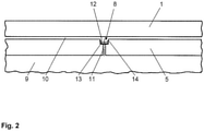
- FIG 2 shows a schematic representation of a venting device 8.
- the venting device 8 is integrated into each stage casing 5.
- the stage housing 5 separates an inner pressure chamber 9 from an outer pressure chamber 10.
- the inner pressure chamber 9 is arranged around the impellers 4.
- the outer pressure chamber 10 is located between the stage casing 5 and the shell casing 1 and is in pressure connection with the interior of the pressure socket 7 .
- the ventilation device 8 comprises an opening 11 which is introduced into the stage housing 5 as a bore. Furthermore, the venting device 8 includes a receptacle 12.
- the receptacle 12 is a recess which is made as a circular recess in the outer surface of the Stage housing 5 is introduced in the form of a bore. It forms an area of the opening 11 with an enlarged inner diameter.
- An element 13 is arranged in the receptacle 12 .
- the element 13 is a disk-like element that is cylindrical. The diameter of the element 13 is smaller than the diameter of the receptacle 12, so that the element 13 is arranged in the receptacle 12 so that it can be displaced in the radial direction.
- the ventilation device 8 comprises a stop 14 which prevents the element 13 from being carried out of the receptacle 12.
- the stop 14 can be projections that protrude into the receptacle 12 or a snap ring inserted into an annular groove provided in the receptacle 12 .
- the element 13 is pressed upwards or outwards in the radial direction and releases a free cross-section for the air to escape.
- the stop 14 is considered a safety element and prevents the element 13 from being carried out of the receptacle 12, for example due to vibrations during operation or due to the air flow during venting.
- the rising operating medium in the inner pressure chamber 9 lifts the element 13 through the hydrostatic water column until all the air has escaped.
- the completely vented system is now put into operation.
- the operating pressure in the outer pressure chamber 10 is higher than that in the inner pressure chamber 9 .
- the element is pressed against the bottom of the receptacle 12 of the stage casing 5 by this pressure difference.
- the element 13 is designed as a sealing element and prevents the operating medium from flowing back from the outer pressure chamber 10 into the inner pressure chamber 9 .
- the contact surfaces between the bottom of the receptacle 12 and the element 13 are designed in such a way that a reliable seal is ensured.
- the venting device according to the invention does not require any spring elements at all. By dispensing with spring elements, the venting device according to the invention proves to be wear-free and low-maintenance. It is characterized by a reliable mode of operation and a long service life. Apart from the operating medium, no other energy source is required. Thus, the ventilation device according to the invention is independent of external energy sources and does not additionally increase the operating costs.
Landscapes
- Engineering & Computer Science (AREA)
- General Engineering & Computer Science (AREA)
- Mechanical Engineering (AREA)
- Structures Of Non-Positive Displacement Pumps (AREA)
- Control Of Positive-Displacement Pumps (AREA)
- Details Of Reciprocating Pumps (AREA)
Description
- Die Erfindung betrifft eine Kreiselpumpe mit einem Mantelgehäuse gemäß dem Oberbegriff von Anspruch 1.
- In dem Mantelgehäuse ist ein Einschub angeordnet ist, der eine Welle aufweist, auf der mindestens ein Laufrad angeordnet ist, das von einem Stufengehäuse umgeben ist, welches einen inneren Druckraum von einem äußeren Druckraum trennt.
- Derartige Kreiselpumpenbauarten werden auch als Mantelgehäusepumpen, Doppelgehäusepumpen bzw. "Barrel-Type"-Pumpen oder Topfpumpen benannt. Eine solche Mantelgehäusepumpe wird beispielsweise in der
DE 40 05 923 A1 beschrieben. - Diese Pumpen sind von einem topfähnlichen Gehäuse umgeben. Häufig handelt es sich hierbei um mehrstufige Pumpen zur Verwendung als Hoch- und Höchstdruckpumpen, insbesondere auch zum Einsatz als Kesselspeisepumpen in Kraftwerken. Zudem kommen solche mehrstufigen Mantelgehäusepumpen in der Stahlindustrie und in der Petrochemie, beispielsweise bei Raffinerien, zum Einsatz.
- In der
DE 43 10 467 A1 wird eine Kreiselpumpe in Topfgehäusebauart beschrieben. Zwischen den einzelnen Pumpenlaufrädern sind strömungsführende Stufengehäuse angeordnet. - Die
DE 298 19 363 U1 betrifft eine Kreiselpumpe mit einem Mantelgehäuse. Das Mantelgehäuse verfügt über einen Einlass, durch den ein Fördermedium einströmt. In dem Mantelgehäuse ist ein Einschub angeordnet. Der Einschub besteht aus einer Welle, auf der mehrere Laufräder und Leiträder mit den zugehörigen Stufengehäusen angeordnet sind. Die Stufengehäuse trennen einen inneren Druckraum, in dem die Laufräder angeordnet sind, von einem äußeren Druckraum zwischen den Stufengehäusen und dem Mantelgehäuse. - Die
DE 44 15 157 A1 beschreibt eine selbstansaugende mehrstufige Pumpe, bei welcher in einem Bereich zwischen Saugbereich und erster Pumpenstufe und einer an einem Druckstutzen angeschlossenen Druckleitung eine Vorrichtung in Form eines Ventils aufweist, welches das Einströmen von Gas aus dem Druckbereich in den Saugbereich während des Ansaugvorgangs verhindert. - Die
EP 1 013 936 A1 offenbart für Pumpentypen, wie sie in derDE 44 15 157 A1 beschrieben werden, eine besondere Ausführungsform des Ventils. -
SU1078134 - Mantelgehäusepumpen müssen vor ihrem Einsatz einer Druckprüfung unterzogen werden. Bei herkömmlichen Mantelgehäusepumpen wird dazu das Mantelgehäuse, welches die Druckhülle der Pumpe bildet, auf den maximalen Abpressdruck der Druckseite ausgelegt. Der Drucktest muss vor der Endmontage durchgeführt werden.
- Aufgabe der Erfindung ist es, eine Mantelgehäusepumpe zu schaffen, bei der ein Drucktest im montierten Zustand möglich ist. Die Pumpe soll sich durch eine zuverlässige und kostengünstige Betriebsweise auszeichnen. Zudem soll sie eine hohe Lebensdauer aufweisen. Weiterhin soll sich die Mantelgehäusepumpe möglichst preiswert fertigen lassen und soll sich durch eine einfache Montage auszeichnen. Wiederholprüfungen in der Anlage sollen zeitsparend und risikoarm sein.
- Diese Aufgabe wird durch eine Kreiselpumpe mit den Merkmalen des Anspruchs 1 und des zugehörigen Verfahrensanspruchs 7 gelöst. Bevorzugte Varianten sind in den Unteransprüchen ausgeführt.
- Erfindungsgemäß ist in einem Stufengehäuse der Kreiselpumpe eine Öffnung zur Entlüftung eingebracht. Die erfindungsgemäße Kreiselpumpe ermöglicht das Füllen der Pumpe in komplett montiertem Zustand mit automatischer Entlüftung der Stufengehäuse. Im Gegensatz zu herkömmlichen Mantelgehäusepumpen, bei denen keine Luft aus einem inneren Druckraum über die Stufengehäuse entweichen kann, da die Trennfuge zwischen den Stufengehäusen metallisch dichtend ist, weist die erfindungsgemäße Pumpe eine Entlüftungseinrichtung auf.
- Die Entlüftungseinrichtung umfasst erfindungsgemäß mindestens eine Öffnung, die den inneren Druckraum mit dem äußeren Druckraum verbindet. Bei herkömmlichen Kreiselpumpen nimmt die Umrüstung einer Pumpe zur hydrostatischen Druckprüfung beispielsweise in einem Kraftwerk oder in einer Raffinerie mehrere Arbeitstage in Anspruch. Dieser erhebliche Zeitaufwand wird beim Einsatz der erfindungsgemäßen Mantelgehäusepumpe größtenteils eingespart, da die wenigstens teilweise Demontage der Pumpe und das Trennen der Druckhülle in einen Hoch- und einen Niederdruckraum mittels eines Spezialwerkzeuges entfällt. Dies ermöglicht eine erhebliche Kostenreduzierung, da bei Kraftwerken bzw. in Raffinerien häufig mehrere Mantelgehäusepumpen zum parallelen Einsatz kommen und durch die erfindungsgemäße Konstruktion bei jeder dieser Pumpen ein erheblicher Arbeitsaufwand eingespart wird.
- Die Pumpe wird im komplett montierten Zustand gefüllt und über die Entlüftungseinrichtung kann Luft aus dem inneren Druckraum über die Öffnung im Stufengehäuse entweichen. Somit wird eine Mantelgehäusepumpe mit einer automatischen Entlüftung der Stufengehäuse geschaffen.
- Erfindungsgemäß umfasst die Entlüftungseinrichtung ein Element, das eine Freigabe eines Medienaustausches aus dem inneren Druckraum zum äußeren Druckraum oder eine Sperrung des Medienaustausches zwischen dem inneren und äußeren Druckraum bewirken kann. Dieses Element ermöglicht es, dass beim Füllen der Mantelgehäusepumpe Luft über die Entlüftungseinrichtung aus dem inneren Druckraum zunächst entweichen kann. Ist die Mantelgehäusepumpe mit dem Betriebsmedium, beispielsweise Wasser, gefüllt, so verschließt dieses Element die Öffnung und sperrt damit den Medienaustausch zwischen dem inneren und äußeren Druckraum. Dadurch wird verhindert, dass Betriebsmedium von dem äußeren Druckraum in den inneren Druckraum fließt.
- Dieses Element ist in einer Führung angeordnet. Die Führung ermöglicht eine Verschiebung des Elements. Durch diese Verschiebung ist es möglich, dass das Element entweder einen Medienaustausch zwischen dem inneren und dem äußeren Druckraum freigibt, beispielsweise zur Entlüftung, oder einen Medienaustausch sperrt, sodass nach der Füllung der Mantelgehäusepumpe keine Betriebsflüssigkeit vom äußeren Druckraum in den inneren Druckraum zurückfließen kann.
- Dazu ist im Stufengehäuse erfindungsgemäß eine Aufnahme eingebracht sein, in der das Element angeordnet ist. Bei der Aufnahme handelt es sich um eine Bohrung, in welcher das scheibenförmige Element positioniert wird Von den Wänden der Aufnahme werden dabei die seitliche Führung des Elements sowie eine Bewegungsbegrenzung gebildet.
- Erfindungsgemäß geht die Öffnung in eine Aufnahme über. So ist auch die Öffnung als Bohrung in dem Stufengehäuse ausgeführt, wobei der Durchmesser der Öffnungsbohrung kleiner ist als der Durchmesser der Aufnahmebohrung, in der das Element platziert ist. Somit erweitert sich die zwischen dem inneren und äußeren Druckraum in dem Stufengehäuse eingebrachte Verbindung von einem kleineren Öffnungsdurchmesser zu einem größeren Aufnahmedurchmesser, der sowohl als Dichtfläche als auch zur Bewegungsbegrenzung des zur Abdichtung dienenden Elements dient.
- Erfindungsgemäß ist zwischen den Wänden der Aufnahme und dem Element immer noch ein ausreichend großer freier Querschnitt vorhanden, der einen Luftaustritt ermöglicht. Die Luft strömt durch die Öffnung in die Aufnahme und dann durch den freien Querschnitt zwischen dem Element und den Wänden der Aufnahme in den äußeren Druckraum.
- Das Element ist größer als die Öffnung ausgebildet. Dieses Merkmal ist Voraussetzung dafür, dass das Element die Öffnung bei einer Rückströmung des Betriebsmediums verschließen kann. Bei dieser Gestaltung der Erfindung ist die Entlüftungseinrichtung somit mit einer Rückströmsicherung ausgerüstet. Steigt der Druck im äußeren Druckraum über den Druck im inneren Druckraum, wird das Element auf die Öffnung gepresst und ein Medienaustausch wird verhindert.
- Das scheibenförmige Element wird dabei auf den Boden der Aufnahme gepresst und verschließt die in dem Boden der Aufnahme eingebrachte Öffnung mittels einer geeigneten Dichtflächengestaltung, z. B. eine zum Stufengehäuse gerichtete, ringförmige Erhebung, die einstückig mit dem Element ausgebildet ist.
- Vorzugsweise weist die Entlüftungseinrichtung einen Anschlag für das Element auf.
- Dieser kann beispielsweise an den Wänden der Aufnahme angeordnet sein. Dabei kann es sich um einen Vorsprung handeln, der in die Aufnahme hineinragt und somit ein Herausspülen oder Verklemmen des Elementes aus der Aufnahme verhindert. Vorzugsweise ragt dabei der Anschlag nur an einigen Stellen in die Aufnahme hinein, sodass immer noch ein freier Querschnitt zum Austritt der Luft bleibt.
- Die Entlüftungseinrichtung ist vorzugsweise in einem oberen Bereich des Stufengehäuses angeordnet, wobei sich insbesondere eine 12-Uhr-Position eignet, da sich die Luft am höchsten Punkt sammelt.
- Eine weitere Aufgabe der Erfindung besteht darin, ein Verfahren zur Durchführung der Druckprüfung einer Mantelgehäusepumpe zur Verfügung zu stellen.
- Erfindungsgemäß wird die Mantelgehäusepumpe zunächst komplett montiert. Dann wird die Kreiselpumpe mit Betriebsmedium gefüllt. Im erfindungsgemäßen Verfahren kann in komplett montiertem Zustand Luft aus den Stufengehäusen entweichen. Weitere Vorteile und Merkmale der Erfindung ergeben sich aus der Beschreibung eines Ausführungsbeispiels anhand von Zeichnungen und aus den Zeichnungen selbst.
- Dabei zeigt:
- Figur 1
- einen Axialschnitt durch eine Mantelgehäusepumpe,
- Figur 2
- eine schematische Darstellung der Entlüftungseinrichtung.
-
Figur 1 zeigt eine Kreiselpumpe mit einem Mantelgehäuse 1. In dem Mantelgehäuse 1 ist ein Einschub 2 angeordnet. Der Einschub 2 umfasst eine Welle 3, auf der mehrere Laufräder 4 hintereinander angeordnet sind. Bei den Laufrädern 4 handelt es sich im Ausführungsbeispiel um Radialräder. - Jedes Laufrad 4 ist von einem Stufengehäuse 5 umgeben. Benachbarte Stufengehäuse 5 grenzen aneinander an. Die Trennfuge zwischen den Stufengehäusen 5 ist im Ausführungsbeispiel metallisch dichtend.
- Am Mantelgehäuse 1 ist ein Saugstutzen 6 angeformt, durch den das Betriebsmedium in die Kreiselpumpe eintritt. Über einen Druckstutzen 7 verlässt das Betriebsmedium die Kreiselpumpe.
- Erfindungsgemäß ist in den Druckgehäusen 5 in einem oberen Bereich, jeweils in 12-Uhr-Stellung eine Entlüftungseinrichtung 8 angeordnet. Die erfindungsgemäße Mantelgehäusepumpe kann somit im komplett montierten Zustand einer Druckprüfung unterzogen werden. Dies wird durch die Integration der Entlüftungseinrichtungen 8 erst ermöglicht. Die Entlüftungseinrichtungen 8 sorgen dafür, dass die bereits komplett in der Anlage montierten Mantelgehäusepumpen gefüllt werden können und dabei Luft über die Entlüftungseinrichtungen 8 entweichen kann.
-
Figur 2 zeigt eine schematische Darstellung einer Entlüftungseinrichtung 8. Die Entlüftungseinrichtung 8 ist in jedes Stufengehäuse 5 integriert. Das Stufengehäuse 5 trennt einen inneren Druckraum 9 von einem äußeren Druckraum 10. Der innere Druckraum 9 ist um die Laufräder 4 angeordnet. Der äußere Druckraum 10 befindet sich zwischen dem Stufengehäuse 5 und dem Mantelgehäuse 1 und steht drucktechnisch mit dem Inneren des Druckstutzens 7 in Verbindung. - Erfindungsgemäß umfasst die Entlüftungseinrichtung 8 eine Öffnung 11, die in das Stufengehäuse 5 als Bohrung eingebracht ist. Weiterhin umfasst die Entlüftungseinrichtung 8 eine Aufnahme 12. Bei der Aufnahme 12 handelt es sich um eine Vertiefung, die als kreisförmige Aussparung in die äußere Mantelfläche des Stufengehäuses 5 in Form einer Bohrung eingebracht ist. Sie bildet einen Bereich der Öffnung 11 mit vergrößertem Innendurchmesser. In der Aufnahme 12 ist ein Element 13 angeordnet. Bei dem Element 13 handelt es sich um ein scheibenartiges Element, das zylinderförmig ausgebildet ist. Der Durchmesser des Elements 13 ist kleiner als der Durchmesser der Aufnahme 12, sodass das Element 13 in radialer Richtung verschieblich in der Aufnahme 12 angeordnet ist.
- Bei der in
Figur 2 dargestellten Variante umfasst die Entlüftungseinrichtung 8 einen Anschlag 14, der verhindert, dass das Element 13 aus der Aufnahme 12 hinausgetragen wird. Bei dem Anschlag 14 kann es sich um Vorsprünge handeln, die in die Aufnahme 12 hineinragen oder um einen in eine in der Aufnahme 12 vorgesehene Ringnut eingesetzten Sprengring. - Wird die Mantelgehäusepumpe zur Druckprüfung mit Betriebsmedium gefüllt, so wird das Element 13 nach oben bzw. in radialer Richtung nach außen gedrückt und gibt einen freien Querschnitt zum Entweichen der Luft frei. Der Anschlag 14 gilt als Sicherungselement und verhindert, dass das Element 13 aus der Aufnahme 12 hinausgetragen wird, beispielsweise durch Vibrationen im Betrieb oder durch den Luftstrom beim Entlüften. Beim Füllvorgang hebt das ansteigende Betriebsmedium im inneren Druckraum 9 das Element 13 durch die hydrostatische Wassersäule solange an, bis die komplette Luft entwichen ist. Das vollständig entlüftete System wird nun in Betrieb genommen. Im Betrieb stellt sich ein höherer Betriebsdruck im äußeren Druckraum 10 gegenüber dem inneren Druckraum 9 ein. Durch diese Druckdifferenz wird das Element an den Boden der Aufnahme 12 des Stufengehäuses 5 gepresst. Das Element 13 ist als Dichtelement ausgeführt und verhindert, dass Betriebsmedium vom äußeren Druckraum 10 in den inneren Druckraum 9 zurückfließt. Dazu sind die Kontaktflächen zwischen dem Boden der Aufnahme 12 und dem Element 13 so ausgeführt, dass eine zuverlässige Abdichtung gewährleistet wird.
- Die erfindungsgemäße Entlüftungseinrichtung kommt vollständig ohne Federelemente aus. Durch den Verzicht auf Federelemente erweist sich die erfindungsgemäße Entlüftungseinrichtung als verschleißfrei und wartungsarm. Sie zeichnet sich durch eine zuverlässige Betriebsweise und eine hohe Lebensdauer aus. Außer dem Betriebsmedium wird zudem keine weitere Energiequelle benötigt. Somit ist die erfindungsgemäße Entlüftungseinrichtung unabhängig von äußeren Energiequellen und erhöht nicht zusätzlich die Betriebskosten.
Claims (7)
- Kreiselpumpe mit Laufrädern (4), einem Druckstutzen (7), einem Mantelgehäuse (1) und mindestens einem Stufengehäuse (5), welches einen inneren Druckraum (9) von einem äußeren Druckraum (10) trennt, wobei der innere Druckraum (9) um die Laufräder (4) angeordnet ist und sich der äußere Druckraum (10) zwischen dem Stufengehäuse (5) und dem Mantelgehäuse (1) befindet und drucktechnisch mit dem Inneren des Druckstutzens (7) in Verbindung steht, wobei in dem Stufengehäuse (5) mindestens eine Entlüftungseinrichtung (8) angeordnet ist,
wobeidie Entlüftungseinrichtung (8) eine in das Stufengehäuse (5) als Bohrung eingebrachte, den inneren Druckraum (9) mit dem äußeren Druckraum (10) verbindende Öffnung (11) und eine Aufnahme (12) umfasst, wobei es sich bei der Aufnahme (12) um eine Vertiefung handelt, die als kreisförmige Aussparung in die äußere Mantelfläche des Stufengehäuses (5) in Form einer Bohrung eingebracht ist,dadurch gekennzeichnet, dassdie Aufnahme (12) einen Bereich der Öffnung (11) mit vergrößertem Innendurchmesser bildet, und dass die Entlüftungseinrichtung (8) ein scheibenartiges Element (13) zur Freigabe oder zur Sperrung eines Medienaustauschs zwischen dem inneren Druckraum (9) und dem äußeren Druckraum (10) umfasst, das in radialer Richtung verschieblich in der Aufnahme (12) angeordnet ist, wobei zwischen den Wänden der Aufnahme (12) und dem scheibenartigen Element (13) ein freier Querschnitt für einen Medienaustausch vorhanden ist. - Kreiselpumpe nach Anspruch 1, dadurch gekennzeichnet, dass das Element (13) in einer Führung angeordnet ist.
- Kreiselpumpe nach einem der Ansprüche 1 oder 2, dadurch gekennzeichnet, dass in den Boden der Aufnahme (12) die Öffnung (11) eingebracht ist.
- Kreiselpumpe nach einem der Ansprüche 1 bis 3, dadurch gekennzeichnet, dass das Element (13) größer als die Öffnung (11) ausgebildet ist.
- Kreiselpumpe nach einem der Ansprüche 1 bis 4, dadurch gekennzeichnet, dass die Entlüftungseinrichtung (8) einen Anschlag (14) für das Element (13) aufweist.
- Kreiselpumpe nach einem der Ansprüche 1 bis 5, dadurch gekennzeichnet, dass die Entlüftungseinrichtung (8) in einem oberen Bereich des Stufengehäuses (5), vorzugsweise in einer 12-Uhr-Stellung, angeordnet ist.
- Verfahren zur Durchführung einer Druckprüfung bei einer Kreiselpumpe nach einem der Ansprüche 1 bis 6 mit folgenden Schritten:- Montage der Kreiselpumpe in einer Anlage,- Füllen der Kreiselpumpe mit Betriebsmedium,- Entweichen von Luft aus einem inneren Druckraum (9) über ein Stufengehäuse (5) in einen äußeren Druckraum (10).
Priority Applications (1)
| Application Number | Priority Date | Filing Date | Title |
|---|---|---|---|
| PL15739602T PL3175116T3 (pl) | 2014-07-29 | 2015-07-22 | Pompa z korpusem płaszczowym z urządzeniem odpowietrzającym oraz przynależny sposób |
Applications Claiming Priority (2)
| Application Number | Priority Date | Filing Date | Title |
|---|---|---|---|
| DE102014214805.7A DE102014214805A1 (de) | 2014-07-29 | 2014-07-29 | Mantelgehäusepumpe |
| PCT/EP2015/066743 WO2016016060A1 (de) | 2014-07-29 | 2015-07-22 | Mantelgehäusepumpe mit entlüftungseinrichtung sowie zugehöriges verfahren |
Publications (2)
| Publication Number | Publication Date |
|---|---|
| EP3175116A1 EP3175116A1 (de) | 2017-06-07 |
| EP3175116B1 true EP3175116B1 (de) | 2022-03-02 |
Family
ID=53716490
Family Applications (1)
| Application Number | Title | Priority Date | Filing Date |
|---|---|---|---|
| EP15739602.9A Active EP3175116B1 (de) | 2014-07-29 | 2015-07-22 | Mantelgehäusepumpe mit entlüftungseinrichtung sowie zugehöriges verfahren |
Country Status (8)
| Country | Link |
|---|---|
| US (1) | US20170218959A1 (de) |
| EP (1) | EP3175116B1 (de) |
| JP (1) | JP6647277B2 (de) |
| CN (2) | CN106574621A (de) |
| DE (1) | DE102014214805A1 (de) |
| PL (1) | PL3175116T3 (de) |
| RU (1) | RU2690893C2 (de) |
| WO (1) | WO2016016060A1 (de) |
Families Citing this family (5)
| Publication number | Priority date | Publication date | Assignee | Title |
|---|---|---|---|---|
| CN105736389A (zh) * | 2016-04-05 | 2016-07-06 | 江苏振华泵业制造有限公司 | 卧式联体自吸泵组 |
| CN107514384A (zh) * | 2017-09-27 | 2017-12-26 | 上海阿波罗机械股份有限公司 | 应急给水泵 |
| CN110469541A (zh) * | 2018-05-09 | 2019-11-19 | 德昌电机(深圳)有限公司 | 一种排水泵及使用该排水泵的洗衣机 |
| DE102018218989A1 (de) | 2018-11-07 | 2020-05-07 | KSB SE & Co. KGaA | Mantelgehäusepumpe |
| DE102019001882A1 (de) | 2019-03-19 | 2020-09-24 | KSB SE & Co. KGaA | Mantelgehäusepumpe und Herstellungsverfahren für eine Mantelgehäusepumpe |
Family Cites Families (23)
| Publication number | Priority date | Publication date | Assignee | Title |
|---|---|---|---|---|
| US3228343A (en) * | 1964-05-25 | 1966-01-11 | U S Pumps Inc | Self-priming pump |
| US3580275A (en) * | 1969-02-24 | 1971-05-25 | Tiona Betts Inc | Valve |
| JPS53130503U (de) * | 1977-03-23 | 1978-10-17 | ||
| DE3172590D1 (en) * | 1981-06-19 | 1985-11-14 | Sulzer Ag | Distributor element for a lubrication apparatus, more specifically for a loom |
| US4523610A (en) * | 1982-05-24 | 1985-06-18 | Honeywell Inc. | Check valve |
| SU1078134A1 (ru) * | 1982-07-08 | 1984-03-07 | Институт ядерной энергетики АН БССР | Горизонтальный многоступенчатый центробежный насос с двойным корпусом |
| US4535820A (en) * | 1984-05-24 | 1985-08-20 | Burron Medical Inc. | Normally closed check valve |
| DE4005923C2 (de) | 1990-02-24 | 1994-08-18 | Klein Schanzlin & Becker Ag | Kreiselpumpe mit Laufrädern unterschiedlicher Drehzahl |
| IT1257704B (it) * | 1991-12-05 | 1996-02-01 | Nocchi Pompe Spa | Pompa per acqua plurifunzionale: centrifuga, per aspirazione profonda,autoadescante, centrifuga con regolazione di pressione, autoadescante con regolazione di pressione, con dispositivo di avviamento e/0 arresto automatico |
| US5341883A (en) * | 1993-01-14 | 1994-08-30 | Halliburton Company | Pressure test and bypass valve with rupture disc |
| DE4310467A1 (de) | 1993-03-31 | 1994-10-06 | Klein Schanzlin & Becker Ag | Topfgehäusepumpe |
| DE4415157A1 (de) * | 1994-05-02 | 1995-11-09 | Klein Schanzlin & Becker Ag | Selbstansaugende mehrstufige Kreiselpumpe |
| DE29819363U1 (de) | 1998-10-30 | 1999-02-18 | KSB AG, 67227 Frankenthal | Kompensator |
| FR2787526B1 (fr) * | 1998-12-21 | 2001-02-09 | Pompes Salmson Sa | Clapet d'amorcage pour pompe autoamorcante |
| US6682313B1 (en) * | 2000-12-04 | 2004-01-27 | Trident Emergency Products, Llc | Compressed air powered pump priming system |
| RU27170U1 (ru) * | 2002-09-16 | 2003-01-10 | Акционерное общество открытого типа "Ленинградский Металлический завод" | Устройство деаэрации проточной части вертикального центробежного насоса системы регулирования турбоагрегата |
| CN2581736Y (zh) * | 2002-09-24 | 2003-10-22 | 浙江科尔泵业股份有限公司 | 超高压双壳体刚性轴低比转速多级离心泵 |
| TWI384123B (zh) * | 2006-02-23 | 2013-02-01 | Levitronix Technologies Llc | 旋轉泵,具有旋轉泵的液體動力混合機,及使用旋轉泵來處理流體 |
| AU2008202487B2 (en) * | 2007-06-05 | 2013-07-04 | Resmed Motor Technologies Inc. | Blower with Bearing Tube |
| PL405594A1 (pl) * | 2011-01-19 | 2014-05-12 | Nexen Inc. | Wysokociśnieniowa wielostopniowa pompa odśrodkowa do szczelinowania rezerwuarów węglowodorów |
| EP2505842B1 (de) * | 2011-03-29 | 2019-12-25 | Grundfos Management a/s | Mehrstufiges kreiselpumpenaggregat |
| US9726183B2 (en) * | 2013-03-13 | 2017-08-08 | Baker Hughes Incorporated | Systems and methods for preventing damage to pump diffusers |
| WO2014187648A1 (de) * | 2013-05-22 | 2014-11-27 | Grundfos Holding A/S | Mehrstufiges selbstansaugendes kreiselpumpenaggregat |
-
2014
- 2014-07-29 DE DE102014214805.7A patent/DE102014214805A1/de not_active Withdrawn
-
2015
- 2015-07-22 US US15/329,689 patent/US20170218959A1/en not_active Abandoned
- 2015-07-22 RU RU2017106525A patent/RU2690893C2/ru active
- 2015-07-22 CN CN201580041744.0A patent/CN106574621A/zh active Pending
- 2015-07-22 EP EP15739602.9A patent/EP3175116B1/de active Active
- 2015-07-22 WO PCT/EP2015/066743 patent/WO2016016060A1/de not_active Ceased
- 2015-07-22 CN CN202210861025.5A patent/CN115143115B/zh active Active
- 2015-07-22 JP JP2017504694A patent/JP6647277B2/ja active Active
- 2015-07-22 PL PL15739602T patent/PL3175116T3/pl unknown
Also Published As
| Publication number | Publication date |
|---|---|
| WO2016016060A1 (de) | 2016-02-04 |
| CN115143115A (zh) | 2022-10-04 |
| CN115143115B (zh) | 2025-07-08 |
| RU2017106525A (ru) | 2018-08-28 |
| US20170218959A1 (en) | 2017-08-03 |
| RU2690893C2 (ru) | 2019-06-06 |
| PL3175116T3 (pl) | 2022-07-11 |
| EP3175116A1 (de) | 2017-06-07 |
| CN106574621A (zh) | 2017-04-19 |
| JP2017522498A (ja) | 2017-08-10 |
| DE102014214805A1 (de) | 2016-02-04 |
| JP6647277B2 (ja) | 2020-02-14 |
| RU2017106525A3 (de) | 2018-11-07 |
Similar Documents
| Publication | Publication Date | Title |
|---|---|---|
| WO2016016060A1 (de) | Mantelgehäusepumpe mit entlüftungseinrichtung sowie zugehöriges verfahren | |
| EP3224483B1 (de) | Kreiselpumpe mit einer leiteinrichtung | |
| DE112017001529B4 (de) | Turbolader | |
| EP3156661B1 (de) | Hauswasserwerk oder pumpe mit einem rückschlagventil | |
| DE102015120304A1 (de) | Vakuumpumpe mit Schalldämpfung und Rückschlagventil | |
| DE10019911A1 (de) | Förderpumpe | |
| EP2815129A1 (de) | Dichtungsanordnung und pumpe mit einer dichtungsanordnung | |
| DE2327814A1 (de) | Hydropumpe mit entlueftungsventil | |
| DE102016225533B4 (de) | Pumpenanordnung und Nuklearreaktor mit einer solchen Pumpenanordnung | |
| DE102013005517B4 (de) | Förderaggregat und Verfahren zur Förderung von festkörperhaltigen Medien | |
| DE102016224228A1 (de) | Reibungskupplung oder -bremse | |
| DE102005034341A1 (de) | Tauchmotorpumpe mit Kühlmantel | |
| US20180221797A1 (en) | No Filter No Run Fluid Filtration System | |
| DE3816280C2 (de) | Gehäuseteil für Kreiselpumpen | |
| DE102011100385A1 (de) | Modul umfassend einen Fluidkühler und einen Fluidfilter, Leitungsvorrichtung eines Fluidkreislaufs einer Brennkraftmaschine und Verfahren zum Betrieb einer Leitungsvorrichtung | |
| DE102015112672A1 (de) | Verdrängerpumpe zur förderung eines fluides für einen verbraucher eines kraftfahrzeuges | |
| DE102016202940A1 (de) | Vorrichtung zum Komprimieren oder Expandieren eines Fluids, Verdichter und Turbine | |
| WO2016091409A1 (de) | Kraftstoffpumpenanordnung | |
| DE102016200910A1 (de) | Anlage | |
| DE1167966C2 (de) | Abdichtungsvorrichtung zwischen einer Gasumwaelzpumpe und dem fluessigkeitsgefuellten elektrischen Antriebsmotor | |
| DE102015206684B4 (de) | Pumpenvorrichtung | |
| EP0953772B1 (de) | Kreiselmotorpumpe mit Entlüftungsschraube | |
| DE102006039712A1 (de) | Förderaggregat | |
| DE102011050658A1 (de) | Vorrichtung zum Fördern und/oder Komprimieren von Fluiden | |
| DE102011086357A1 (de) | Rohrförmiger Filter einer Fahrzeugbremsanlagen-Kolbenpumpe |
Legal Events
| Date | Code | Title | Description |
|---|---|---|---|
| STAA | Information on the status of an ep patent application or granted ep patent |
Free format text: STATUS: THE INTERNATIONAL PUBLICATION HAS BEEN MADE |
|
| 17P | Request for examination filed |
Effective date: 20161118 |
|
| AK | Designated contracting states |
Kind code of ref document: A1 Designated state(s): AL AT BE BG CH CY CZ DE DK EE ES FI FR GB GR HR HU IE IS IT LI LT LU LV MC MK MT NL NO PL PT RO RS SE SI SK SM TR |
|
| AX | Request for extension of the european patent |
Extension state: BA ME |
|
| PUAI | Public reference made under article 153(3) epc to a published international application that has entered the european phase |
Free format text: ORIGINAL CODE: 0009012 |
|
| STAA | Information on the status of an ep patent application or granted ep patent |
Free format text: STATUS: REQUEST FOR EXAMINATION WAS MADE |
|
| DAV | Request for validation of the european patent (deleted) | ||
| DAX | Request for extension of the european patent (deleted) | ||
| RAP1 | Party data changed (applicant data changed or rights of an application transferred) |
Owner name: KSB SE & CO. KGAA |
|
| STAA | Information on the status of an ep patent application or granted ep patent |
Free format text: STATUS: EXAMINATION IS IN PROGRESS |
|
| 17Q | First examination report despatched |
Effective date: 20210331 |
|
| REG | Reference to a national code |
Ref country code: DE Ref legal event code: R079 Ref document number: 502015015679 Country of ref document: DE Free format text: PREVIOUS MAIN CLASS: F04D0001060000 Ipc: F16K0015020000 |
|
| GRAP | Despatch of communication of intention to grant a patent |
Free format text: ORIGINAL CODE: EPIDOSNIGR1 |
|
| STAA | Information on the status of an ep patent application or granted ep patent |
Free format text: STATUS: GRANT OF PATENT IS INTENDED |
|
| RIC1 | Information provided on ipc code assigned before grant |
Ipc: F04D 9/00 20060101ALI20211001BHEP Ipc: F04D 1/06 20060101ALI20211001BHEP Ipc: F16K 15/02 20060101AFI20211001BHEP |
|
| INTG | Intention to grant announced |
Effective date: 20211019 |
|
| GRAS | Grant fee paid |
Free format text: ORIGINAL CODE: EPIDOSNIGR3 |
|
| GRAA | (expected) grant |
Free format text: ORIGINAL CODE: 0009210 |
|
| STAA | Information on the status of an ep patent application or granted ep patent |
Free format text: STATUS: THE PATENT HAS BEEN GRANTED |
|
| AK | Designated contracting states |
Kind code of ref document: B1 Designated state(s): AL AT BE BG CH CY CZ DE DK EE ES FI FR GB GR HR HU IE IS IT LI LT LU LV MC MK MT NL NO PL PT RO RS SE SI SK SM TR |
|
| REG | Reference to a national code |
Ref country code: GB Ref legal event code: FG4D Free format text: NOT ENGLISH |
|
| REG | Reference to a national code |
Ref country code: CH Ref legal event code: EP Ref country code: AT Ref legal event code: REF Ref document number: 1472500 Country of ref document: AT Kind code of ref document: T Effective date: 20220315 |
|
| REG | Reference to a national code |
Ref country code: DE Ref legal event code: R096 Ref document number: 502015015679 Country of ref document: DE |
|
| REG | Reference to a national code |
Ref country code: IE Ref legal event code: FG4D Free format text: LANGUAGE OF EP DOCUMENT: GERMAN |
|
| REG | Reference to a national code |
Ref country code: FI Ref legal event code: FGE |
|
| REG | Reference to a national code |
Ref country code: LT Ref legal event code: MG9D |
|
| REG | Reference to a national code |
Ref country code: NL Ref legal event code: MP Effective date: 20220302 |
|
| PG25 | Lapsed in a contracting state [announced via postgrant information from national office to epo] |
Ref country code: SE Free format text: LAPSE BECAUSE OF FAILURE TO SUBMIT A TRANSLATION OF THE DESCRIPTION OR TO PAY THE FEE WITHIN THE PRESCRIBED TIME-LIMIT Effective date: 20220302 Ref country code: RS Free format text: LAPSE BECAUSE OF FAILURE TO SUBMIT A TRANSLATION OF THE DESCRIPTION OR TO PAY THE FEE WITHIN THE PRESCRIBED TIME-LIMIT Effective date: 20220302 Ref country code: NO Free format text: LAPSE BECAUSE OF FAILURE TO SUBMIT A TRANSLATION OF THE DESCRIPTION OR TO PAY THE FEE WITHIN THE PRESCRIBED TIME-LIMIT Effective date: 20220602 Ref country code: LT Free format text: LAPSE BECAUSE OF FAILURE TO SUBMIT A TRANSLATION OF THE DESCRIPTION OR TO PAY THE FEE WITHIN THE PRESCRIBED TIME-LIMIT Effective date: 20220302 Ref country code: HR Free format text: LAPSE BECAUSE OF FAILURE TO SUBMIT A TRANSLATION OF THE DESCRIPTION OR TO PAY THE FEE WITHIN THE PRESCRIBED TIME-LIMIT Effective date: 20220302 Ref country code: ES Free format text: LAPSE BECAUSE OF FAILURE TO SUBMIT A TRANSLATION OF THE DESCRIPTION OR TO PAY THE FEE WITHIN THE PRESCRIBED TIME-LIMIT Effective date: 20220302 Ref country code: BG Free format text: LAPSE BECAUSE OF FAILURE TO SUBMIT A TRANSLATION OF THE DESCRIPTION OR TO PAY THE FEE WITHIN THE PRESCRIBED TIME-LIMIT Effective date: 20220602 |
|
| REG | Reference to a national code |
Ref country code: HU Ref legal event code: AG4A Ref document number: E058505 Country of ref document: HU |
|
| PG25 | Lapsed in a contracting state [announced via postgrant information from national office to epo] |
Ref country code: LV Free format text: LAPSE BECAUSE OF FAILURE TO SUBMIT A TRANSLATION OF THE DESCRIPTION OR TO PAY THE FEE WITHIN THE PRESCRIBED TIME-LIMIT Effective date: 20220302 Ref country code: GR Free format text: LAPSE BECAUSE OF FAILURE TO SUBMIT A TRANSLATION OF THE DESCRIPTION OR TO PAY THE FEE WITHIN THE PRESCRIBED TIME-LIMIT Effective date: 20220603 |
|
| PG25 | Lapsed in a contracting state [announced via postgrant information from national office to epo] |
Ref country code: NL Free format text: LAPSE BECAUSE OF FAILURE TO SUBMIT A TRANSLATION OF THE DESCRIPTION OR TO PAY THE FEE WITHIN THE PRESCRIBED TIME-LIMIT Effective date: 20220302 |
|
| PG25 | Lapsed in a contracting state [announced via postgrant information from national office to epo] |
Ref country code: SM Free format text: LAPSE BECAUSE OF FAILURE TO SUBMIT A TRANSLATION OF THE DESCRIPTION OR TO PAY THE FEE WITHIN THE PRESCRIBED TIME-LIMIT Effective date: 20220302 Ref country code: SK Free format text: LAPSE BECAUSE OF FAILURE TO SUBMIT A TRANSLATION OF THE DESCRIPTION OR TO PAY THE FEE WITHIN THE PRESCRIBED TIME-LIMIT Effective date: 20220302 Ref country code: RO Free format text: LAPSE BECAUSE OF FAILURE TO SUBMIT A TRANSLATION OF THE DESCRIPTION OR TO PAY THE FEE WITHIN THE PRESCRIBED TIME-LIMIT Effective date: 20220302 Ref country code: PT Free format text: LAPSE BECAUSE OF FAILURE TO SUBMIT A TRANSLATION OF THE DESCRIPTION OR TO PAY THE FEE WITHIN THE PRESCRIBED TIME-LIMIT Effective date: 20220704 Ref country code: EE Free format text: LAPSE BECAUSE OF FAILURE TO SUBMIT A TRANSLATION OF THE DESCRIPTION OR TO PAY THE FEE WITHIN THE PRESCRIBED TIME-LIMIT Effective date: 20220302 |
|
| PG25 | Lapsed in a contracting state [announced via postgrant information from national office to epo] |
Ref country code: IS Free format text: LAPSE BECAUSE OF FAILURE TO SUBMIT A TRANSLATION OF THE DESCRIPTION OR TO PAY THE FEE WITHIN THE PRESCRIBED TIME-LIMIT Effective date: 20220702 Ref country code: AL Free format text: LAPSE BECAUSE OF FAILURE TO SUBMIT A TRANSLATION OF THE DESCRIPTION OR TO PAY THE FEE WITHIN THE PRESCRIBED TIME-LIMIT Effective date: 20220302 |
|
| REG | Reference to a national code |
Ref country code: DE Ref legal event code: R097 Ref document number: 502015015679 Country of ref document: DE |
|
| PLBE | No opposition filed within time limit |
Free format text: ORIGINAL CODE: 0009261 |
|
| STAA | Information on the status of an ep patent application or granted ep patent |
Free format text: STATUS: NO OPPOSITION FILED WITHIN TIME LIMIT |
|
| PG25 | Lapsed in a contracting state [announced via postgrant information from national office to epo] |
Ref country code: DK Free format text: LAPSE BECAUSE OF FAILURE TO SUBMIT A TRANSLATION OF THE DESCRIPTION OR TO PAY THE FEE WITHIN THE PRESCRIBED TIME-LIMIT Effective date: 20220302 |
|
| 26N | No opposition filed |
Effective date: 20221205 |
|
| PG25 | Lapsed in a contracting state [announced via postgrant information from national office to epo] |
Ref country code: SI Free format text: LAPSE BECAUSE OF FAILURE TO SUBMIT A TRANSLATION OF THE DESCRIPTION OR TO PAY THE FEE WITHIN THE PRESCRIBED TIME-LIMIT Effective date: 20220302 Ref country code: MC Free format text: LAPSE BECAUSE OF FAILURE TO SUBMIT A TRANSLATION OF THE DESCRIPTION OR TO PAY THE FEE WITHIN THE PRESCRIBED TIME-LIMIT Effective date: 20220302 |
|
| REG | Reference to a national code |
Ref country code: CH Ref legal event code: PL |
|
| GBPC | Gb: european patent ceased through non-payment of renewal fee |
Effective date: 20220722 |
|
| REG | Reference to a national code |
Ref country code: BE Ref legal event code: MM Effective date: 20220731 |
|
| PG25 | Lapsed in a contracting state [announced via postgrant information from national office to epo] |
Ref country code: LU Free format text: LAPSE BECAUSE OF NON-PAYMENT OF DUE FEES Effective date: 20220722 Ref country code: LI Free format text: LAPSE BECAUSE OF NON-PAYMENT OF DUE FEES Effective date: 20220731 Ref country code: FR Free format text: LAPSE BECAUSE OF NON-PAYMENT OF DUE FEES Effective date: 20220731 Ref country code: CH Free format text: LAPSE BECAUSE OF NON-PAYMENT OF DUE FEES Effective date: 20220731 |
|
| PG25 | Lapsed in a contracting state [announced via postgrant information from national office to epo] |
Ref country code: GB Free format text: LAPSE BECAUSE OF NON-PAYMENT OF DUE FEES Effective date: 20220722 Ref country code: BE Free format text: LAPSE BECAUSE OF NON-PAYMENT OF DUE FEES Effective date: 20220731 |
|
| PG25 | Lapsed in a contracting state [announced via postgrant information from national office to epo] |
Ref country code: IT Free format text: LAPSE BECAUSE OF FAILURE TO SUBMIT A TRANSLATION OF THE DESCRIPTION OR TO PAY THE FEE WITHIN THE PRESCRIBED TIME-LIMIT Effective date: 20220302 Ref country code: IE Free format text: LAPSE BECAUSE OF NON-PAYMENT OF DUE FEES Effective date: 20220722 |
|
| PGFP | Annual fee paid to national office [announced via postgrant information from national office to epo] |
Ref country code: CZ Payment date: 20230621 Year of fee payment: 9 |
|
| P01 | Opt-out of the competence of the unified patent court (upc) registered |
Effective date: 20230704 |
|
| PGFP | Annual fee paid to national office [announced via postgrant information from national office to epo] |
Ref country code: PL Payment date: 20230622 Year of fee payment: 9 |
|
| REG | Reference to a national code |
Ref country code: AT Ref legal event code: MM01 Ref document number: 1472500 Country of ref document: AT Kind code of ref document: T Effective date: 20220722 |
|
| PG25 | Lapsed in a contracting state [announced via postgrant information from national office to epo] |
Ref country code: AT Free format text: LAPSE BECAUSE OF NON-PAYMENT OF DUE FEES Effective date: 20220722 |
|
| PGFP | Annual fee paid to national office [announced via postgrant information from national office to epo] |
Ref country code: TR Payment date: 20230713 Year of fee payment: 9 Ref country code: FI Payment date: 20230721 Year of fee payment: 9 |
|
| PGFP | Annual fee paid to national office [announced via postgrant information from national office to epo] |
Ref country code: HU Payment date: 20230707 Year of fee payment: 9 |
|
| PG25 | Lapsed in a contracting state [announced via postgrant information from national office to epo] |
Ref country code: MK Free format text: LAPSE BECAUSE OF FAILURE TO SUBMIT A TRANSLATION OF THE DESCRIPTION OR TO PAY THE FEE WITHIN THE PRESCRIBED TIME-LIMIT Effective date: 20220302 Ref country code: CY Free format text: LAPSE BECAUSE OF FAILURE TO SUBMIT A TRANSLATION OF THE DESCRIPTION OR TO PAY THE FEE WITHIN THE PRESCRIBED TIME-LIMIT Effective date: 20220302 |
|
| PG25 | Lapsed in a contracting state [announced via postgrant information from national office to epo] |
Ref country code: MT Free format text: LAPSE BECAUSE OF FAILURE TO SUBMIT A TRANSLATION OF THE DESCRIPTION OR TO PAY THE FEE WITHIN THE PRESCRIBED TIME-LIMIT Effective date: 20220302 |
|
| PG25 | Lapsed in a contracting state [announced via postgrant information from national office to epo] |
Ref country code: HU Free format text: LAPSE BECAUSE OF NON-PAYMENT OF DUE FEES Effective date: 20240723 |
|
| PG25 | Lapsed in a contracting state [announced via postgrant information from national office to epo] |
Ref country code: HU Free format text: LAPSE BECAUSE OF NON-PAYMENT OF DUE FEES Effective date: 20240723 |
|
| PG25 | Lapsed in a contracting state [announced via postgrant information from national office to epo] |
Ref country code: FI Free format text: LAPSE BECAUSE OF NON-PAYMENT OF DUE FEES Effective date: 20240722 |
|
| PG25 | Lapsed in a contracting state [announced via postgrant information from national office to epo] |
Ref country code: CZ Free format text: LAPSE BECAUSE OF NON-PAYMENT OF DUE FEES Effective date: 20240722 |
|
| PGFP | Annual fee paid to national office [announced via postgrant information from national office to epo] |
Ref country code: DE Payment date: 20250731 Year of fee payment: 11 |
|
| PG25 | Lapsed in a contracting state [announced via postgrant information from national office to epo] |
Ref country code: PL Free format text: LAPSE BECAUSE OF NON-PAYMENT OF DUE FEES Effective date: 20240722 |