EP3173821A1 - Distinction de dispositifs ayant des positions et directions - Google Patents
Distinction de dispositifs ayant des positions et directions Download PDFInfo
- Publication number
- EP3173821A1 EP3173821A1 EP16198898.5A EP16198898A EP3173821A1 EP 3173821 A1 EP3173821 A1 EP 3173821A1 EP 16198898 A EP16198898 A EP 16198898A EP 3173821 A1 EP3173821 A1 EP 3173821A1
- Authority
- EP
- European Patent Office
- Prior art keywords
- sensor
- controller
- devices
- light detector
- information
- Prior art date
- Legal status (The legal status is an assumption and is not a legal conclusion. Google has not performed a legal analysis and makes no representation as to the accuracy of the status listed.)
- Granted
Links
- 238000000034 method Methods 0.000 claims abstract description 41
- 230000003287 optical effect Effects 0.000 description 3
- 230000007423 decrease Effects 0.000 description 2
- 238000004458 analytical method Methods 0.000 description 1
- 238000010276 construction Methods 0.000 description 1
- 230000001419 dependent effect Effects 0.000 description 1
- 238000002955 isolation Methods 0.000 description 1
Images


Classifications
-
- G—PHYSICS
- G01—MEASURING; TESTING
- G01S—RADIO DIRECTION-FINDING; RADIO NAVIGATION; DETERMINING DISTANCE OR VELOCITY BY USE OF RADIO WAVES; LOCATING OR PRESENCE-DETECTING BY USE OF THE REFLECTION OR RERADIATION OF RADIO WAVES; ANALOGOUS ARRANGEMENTS USING OTHER WAVES
- G01S3/00—Direction-finders for determining the direction from which infrasonic, sonic, ultrasonic, or electromagnetic waves, or particle emission, not having a directional significance, are being received
- G01S3/78—Direction-finders for determining the direction from which infrasonic, sonic, ultrasonic, or electromagnetic waves, or particle emission, not having a directional significance, are being received using electromagnetic waves other than radio waves
- G01S3/782—Systems for determining direction or deviation from predetermined direction
- G01S3/785—Systems for determining direction or deviation from predetermined direction using adjustment of orientation of directivity characteristics of a detector or detector system to give a desired condition of signal derived from that detector or detector system
- G01S3/786—Systems for determining direction or deviation from predetermined direction using adjustment of orientation of directivity characteristics of a detector or detector system to give a desired condition of signal derived from that detector or detector system the desired condition being maintained automatically
- G01S3/7861—Solar tracking systems
-
- G—PHYSICS
- G01—MEASURING; TESTING
- G01S—RADIO DIRECTION-FINDING; RADIO NAVIGATION; DETERMINING DISTANCE OR VELOCITY BY USE OF RADIO WAVES; LOCATING OR PRESENCE-DETECTING BY USE OF THE REFLECTION OR RERADIATION OF RADIO WAVES; ANALOGOUS ARRANGEMENTS USING OTHER WAVES
- G01S19/00—Satellite radio beacon positioning systems; Determining position, velocity or attitude using signals transmitted by such systems
- G01S19/01—Satellite radio beacon positioning systems transmitting time-stamped messages, e.g. GPS [Global Positioning System], GLONASS [Global Orbiting Navigation Satellite System] or GALILEO
- G01S19/13—Receivers
- G01S19/14—Receivers specially adapted for specific applications
-
- G—PHYSICS
- G01—MEASURING; TESTING
- G01S—RADIO DIRECTION-FINDING; RADIO NAVIGATION; DETERMINING DISTANCE OR VELOCITY BY USE OF RADIO WAVES; LOCATING OR PRESENCE-DETECTING BY USE OF THE REFLECTION OR RERADIATION OF RADIO WAVES; ANALOGOUS ARRANGEMENTS USING OTHER WAVES
- G01S19/00—Satellite radio beacon positioning systems; Determining position, velocity or attitude using signals transmitted by such systems
- G01S19/38—Determining a navigation solution using signals transmitted by a satellite radio beacon positioning system
- G01S19/39—Determining a navigation solution using signals transmitted by a satellite radio beacon positioning system the satellite radio beacon positioning system transmitting time-stamped messages, e.g. GPS [Global Positioning System], GLONASS [Global Orbiting Navigation Satellite System] or GALILEO
- G01S19/42—Determining position
- G01S19/48—Determining position by combining or switching between position solutions derived from the satellite radio beacon positioning system and position solutions derived from a further system
- G01S19/485—Determining position by combining or switching between position solutions derived from the satellite radio beacon positioning system and position solutions derived from a further system whereby the further system is an optical system or imaging system
-
- G—PHYSICS
- G01—MEASURING; TESTING
- G01S—RADIO DIRECTION-FINDING; RADIO NAVIGATION; DETERMINING DISTANCE OR VELOCITY BY USE OF RADIO WAVES; LOCATING OR PRESENCE-DETECTING BY USE OF THE REFLECTION OR RERADIATION OF RADIO WAVES; ANALOGOUS ARRANGEMENTS USING OTHER WAVES
- G01S19/00—Satellite radio beacon positioning systems; Determining position, velocity or attitude using signals transmitted by such systems
- G01S19/38—Determining a navigation solution using signals transmitted by a satellite radio beacon positioning system
- G01S19/39—Determining a navigation solution using signals transmitted by a satellite radio beacon positioning system the satellite radio beacon positioning system transmitting time-stamped messages, e.g. GPS [Global Positioning System], GLONASS [Global Orbiting Navigation Satellite System] or GALILEO
- G01S19/42—Determining position
- G01S19/51—Relative positioning
-
- G—PHYSICS
- G01—MEASURING; TESTING
- G01S—RADIO DIRECTION-FINDING; RADIO NAVIGATION; DETERMINING DISTANCE OR VELOCITY BY USE OF RADIO WAVES; LOCATING OR PRESENCE-DETECTING BY USE OF THE REFLECTION OR RERADIATION OF RADIO WAVES; ANALOGOUS ARRANGEMENTS USING OTHER WAVES
- G01S3/00—Direction-finders for determining the direction from which infrasonic, sonic, ultrasonic, or electromagnetic waves, or particle emission, not having a directional significance, are being received
- G01S3/78—Direction-finders for determining the direction from which infrasonic, sonic, ultrasonic, or electromagnetic waves, or particle emission, not having a directional significance, are being received using electromagnetic waves other than radio waves
- G01S3/782—Systems for determining direction or deviation from predetermined direction
- G01S3/783—Systems for determining direction or deviation from predetermined direction using amplitude comparison of signals derived from static detectors or detector systems
-
- H—ELECTRICITY
- H02—GENERATION; CONVERSION OR DISTRIBUTION OF ELECTRIC POWER
- H02J—CIRCUIT ARRANGEMENTS OR SYSTEMS FOR SUPPLYING OR DISTRIBUTING ELECTRIC POWER; SYSTEMS FOR STORING ELECTRIC ENERGY
- H02J4/00—Circuit arrangements for mains or distribution networks not specified as ac or dc
-
- H—ELECTRICITY
- H05—ELECTRIC TECHNIQUES NOT OTHERWISE PROVIDED FOR
- H05B—ELECTRIC HEATING; ELECTRIC LIGHT SOURCES NOT OTHERWISE PROVIDED FOR; CIRCUIT ARRANGEMENTS FOR ELECTRIC LIGHT SOURCES, IN GENERAL
- H05B47/00—Circuit arrangements for operating light sources in general, i.e. where the type of light source is not relevant
- H05B47/10—Controlling the light source
- H05B47/105—Controlling the light source in response to determined parameters
- H05B47/11—Controlling the light source in response to determined parameters by determining the brightness or colour temperature of ambient light
-
- H—ELECTRICITY
- H05—ELECTRIC TECHNIQUES NOT OTHERWISE PROVIDED FOR
- H05B—ELECTRIC HEATING; ELECTRIC LIGHT SOURCES NOT OTHERWISE PROVIDED FOR; CIRCUIT ARRANGEMENTS FOR ELECTRIC LIGHT SOURCES, IN GENERAL
- H05B47/00—Circuit arrangements for operating light sources in general, i.e. where the type of light source is not relevant
- H05B47/10—Controlling the light source
- H05B47/175—Controlling the light source by remote control
- H05B47/19—Controlling the light source by remote control via wireless transmission
-
- Y—GENERAL TAGGING OF NEW TECHNOLOGICAL DEVELOPMENTS; GENERAL TAGGING OF CROSS-SECTIONAL TECHNOLOGIES SPANNING OVER SEVERAL SECTIONS OF THE IPC; TECHNICAL SUBJECTS COVERED BY FORMER USPC CROSS-REFERENCE ART COLLECTIONS [XRACs] AND DIGESTS
- Y02—TECHNOLOGIES OR APPLICATIONS FOR MITIGATION OR ADAPTATION AGAINST CLIMATE CHANGE
- Y02B—CLIMATE CHANGE MITIGATION TECHNOLOGIES RELATED TO BUILDINGS, e.g. HOUSING, HOUSE APPLIANCES OR RELATED END-USER APPLICATIONS
- Y02B20/00—Energy efficient lighting technologies, e.g. halogen lamps or gas discharge lamps
- Y02B20/40—Control techniques providing energy savings, e.g. smart controller or presence detection
Definitions
- the invention relates to a method for distinguishing first and second devices from each other, for example in a commissioning procedure.
- the invention further relates to a first device, to a system and to an apparatus. Examples of such a first device are lighting devices and non-lighting devices, and examples of such an apparatus are commissioning apparatuses.
- a method for distinguishing first and second devices from each other.
- Such a method may comprise a step of receiving first position information from a first position sensor, which first position information is configured to define a first position of the first device, and a step of receiving second position information from a second position sensor, which second position information is configured to define a second position of the second device.
- Such a method may further comprise a step of receiving first direction information from a first direction sensor, which first direction information is configured to define a first direction of the first device, and a step of receiving second direction information from a second direction sensor, which second direction information is configured to define a second direction of the second device.
- Such a method may further comprise a step of analyzing the first and second direction information.
- the first position information originates from the first position sensor and defines the first position of the first device.
- the second position information originates from the second position sensor and defines the second position of the second device.
- the first direction information originates from the first direction sensor and defines the first direction of the first device.
- the second direction information originates from the second direction sensor and defines the second direction of the second device.
- the first and second devices may be mutually different directions.
- the first and second devices have said mutually different directions.
- the first and second devices can be distinguished from each other, even in case they are located closer to each other than the accuracies of their position sensors.
- An embodiment of the method is defined, wherein the defined first and second positions differ insufficiently to distinguish the first and second devices.
- the first and second direction information might be used to distinguish the first and second devices.
- a first device for driving a first load like for example a first light-emitting-element or a first non-lighting-element.
- Such a first device may comprise a first driver configured to be coupled to the first load and configured to drive the first load.
- Such a first device may further comprise a first controller coupled to the first driver and configured to control the first driver, which first controller is further configured to receive a first position signal from a first position sensor, which first position signal is configured to define a first position of the first device, and which first controller is further configured to receive a first direction signal from a first direction sensor, which first direction signal is configured to define a first direction of the first device.
- the first device comprises a first driver that can be coupled to a first load.
- the first driver may drive the first load.
- the first device further comprises a first controller coupled to the first driver.
- the first controller may control the first driver, and may receive a first position signal from the first position sensor, which first position signal defines a first position of the first device, and may receive a first direction signal from the first direction sensor, which first direction signal defines a first direction of the first device.
- the first device can be distinguished from a second device, even in case they are located closer to each other than the accuracies of their position sensors.
- An embodiment of the first device is defined, wherein the first controller is configured to process the first direction signal, or wherein the first controller is configured to process the first direction signal and a second direction signal coming from a second device, or wherein the first controller is configured to forward the first direction signal to a second device or to a third device or to an apparatus.
- the first controller may process the first direction signal, for example to derive the first direction from the first direction signal.
- the first direction may then be forwarded to an apparatus such as a commissioning apparatus.
- the first controller may process the first direction signal and a second direction signal coming from a second device, for example to derive the first and second directions from the first and second direction signals.
- the first and second directions may then be forwarded to an apparatus such as a commissioning apparatus.
- the first controller may forward the first direction signal to a second device located at a relatively short distance from the first device or to a third device located at a relatively large distance from the first device or to an apparatus such as a commissioning apparatus.
- the second device or the third device or the apparatus may then derive the first direction from the first direction signal etc.
- first device further comprising the first position sensor coupled to the first controller.
- the first device may comprise the first position sensor, whereby it is not to be excluded that the first device and the first position sensor are produced separately from each other and sold separately from each other and then combined.
- the first position sensor may comprise a first Global Positioning System sensor or any other kind of first position sensor.
- first device further comprising the first direction sensor coupled to the first controller.
- the first device may comprise the first direction sensor, whereby it is not to be excluded that the first device and the first direction sensor are produced separately from each other and sold separately from each other and then combined.
- the first direction sensor comprises a first light detector configured to detect incoming light from the sun, which first light detector comprises a first multiple field light detector or another kind of first light detector.
- the first direction sensor may comprise a first light detector.
- Such a first light detector may detect incoming light from the sun, and may comprise a first multiple field light detector, such as a quad cell, or another kind of first light detector.
- US 5,483,060 discloses an optical position sensor and isolation sensor using this position sensor. US 5,483,060 is not related to distinguishing first and second devices from each other.
- the first direction sensor further comprises a first shadow producer configured to produce shadow on a part of the first light detector.
- the first direction sensor may further comprise a first shadow producer.
- Such a first shadow producer may produce shadow on a part of the first light detector. The shadow on one part of the first light detector and/or the light on another part of the first light detector will be indicative for a direction of the first light detector (and the first device) with respect to the sun for a given position of the sun as defined by the date and the time.
- the first device further comprising the first load that comprises a first light-emitting-element or a first non-lighting-element.
- the first device may further comprise the first load, whereby it is not to be excluded that the first device and the first load are produced separately from each other and sold separately from each other and then combined.
- the first load may comprise a first light-emitting-element, such as a light emitting diode circuit that comprises one or more light emitting diodes, or a first non-lighting-element.
- a system comprising the first device as defined above and further comprising a second device for driving a second load.
- Such a second device may comprise a second driver configured to be coupled to the second load and configured to drive the second load.
- Such a second device may further comprise a second controller coupled to the second driver and configured to control the second driver, which second controller is further configured to receive a second position signal from a second position sensor, which second position signal is configured to define a second position of the second device, and which second controller is further configured to receive a second direction signal from a second direction sensor, which second direction signal is configured to define a second direction of the second device.
- a second controller coupled to the second driver and configured to control the second driver, which second controller is further configured to receive a second position signal from a second position sensor, which second position signal is configured to define a second position of the second device, and which second controller is further configured to receive a second direction signal from a second direction sensor, which second direction signal is configured to define a second direction of the second device.
- the system further comprises the second device.
- the second device comprises a second driver that can be coupled to a second load.
- the second driver may drive the second load.
- the second device further comprises a second controller coupled to the second driver.
- the second controller may control the second driver, and may receive a second position signal from a second position sensor, which second position signal defines a second position of the second device, and may receive a second direction signal from a second direction sensor, which second direction signal defines a second direction of the second device.
- the first and second directions may be mutually different directions.
- the first and second devices can be distinguished from each other, even in case they are located closer to each other than the accuracies of their position sensors.
- the first controller is configured to process the first direction signal or wherein the first controller is configured to process the first direction signal and the second direction signal or wherein the first controller is configured to forward the first direction signal to the second device or to a third device or to an apparatus
- the second controller is configured to process the second direction signal or wherein the second controller is configured to process the first direction signal and the second direction signal or wherein the second controller is configured to forward the second direction signal to the first device or to a fourth device or to an apparatus.
- the first controller may process the first direction signal, for example to derive the first direction from the first direction signal.
- the first direction may then be forwarded to an apparatus such as a commissioning apparatus.
- the first controller may process the first direction signal and a second direction signal coming from a second device, for example to derive the first and second directions from the first and second direction signals.
- the first and second directions may then be forwarded to an apparatus such as a commissioning apparatus.
- the first controller may forward the first direction signal to a second device located at a relatively short distance from the first device or to a third device located at a relatively large distance from the first device or to an apparatus such as a commissioning apparatus.
- the second device or the third device or the apparatus may then derive the first direction from the first direction signal etc.
- the second controller may process the second direction signal, for example to derive the second direction from the second direction signal.
- the second direction may then be forwarded to an apparatus such as a commissioning apparatus.
- the second controller may process the first direction signal coming from the first device and the second direction signal, for example to derive the first and second directions from the first and second direction signals.
- the first and second directions may then be forwarded to an apparatus such as a commissioning apparatus.
- the second controller may forward the second direction signal to the first device located at a relatively short distance from the second device or to a fourth device located at a relatively large distance from the second device or to an apparatus such as a commissioning apparatus.
- the first device or the fourth device or the apparatus may then derive the second direction from the second direction signal etc.
- the third and fourth devices may be the same device or may be different devices.
- first device further comprises the first direction sensor coupled to the first controller
- second device further comprises the second direction sensor coupled to the second controller, and wherein the first and second direction signals are different from each other.
- the first device may comprise the first direction sensor, whereby it is not to be excluded that the first device and the first direction sensor are produced separately from each other and sold separately from each other and then combined.
- the second device may comprise the second direction sensor, whereby it is not to be excluded that the second device and the second direction sensor are produced separately from each other and sold separately from each other and then combined.
- the first and second direction signals are different from each other to allow the first and second devices to be distinguished from each other.
- the first direction sensor comprises a first light detector configured to detect incoming light from the sun, which first light detector comprises a first multiple field light detector or another kind of first light detector
- the second direction sensor comprises a second light detector configured to detect the incoming light from the sun, which second light detector comprises a second multiple field light detector or another kind of second light detector.
- the first direction sensor may comprise a first light detector.
- a first light detector may detect incoming light from the sun, and may comprise a first multiple field light detector, such as a quad cell, or another kind of first light detector.
- the second direction sensor may comprise a second light detector.
- a second light detector may detect incoming light from the sun, and may comprise a second multiple field light detector, such as a quad cell, or another kind of second light detector.
- first direction sensor further comprises a first shadow producer configured to produce shadow on a part of the first light detector
- second direction sensor further comprises a second shadow producer configured to produce shadow on a part of the second light detector
- the first direction sensor may further comprise a first shadow producer.
- a first shadow producer may produce shadow on a part of the first light detector.
- the shadow on one part of the first light detector and/or the light on another part of the first light detector will be indicative for a direction of the first light detector (and the first device) with respect to the sun for a given position of the sun as defined by the date and the time.
- the second direction sensor may further comprise a second shadow producer.
- a second shadow producer may produce shadow on a part of the second light detector.
- the shadow on one part of the second light detector and/or the light on another part of the second light detector will be indicative for a direction of the second light detector (and the second device) with respect to the sun for a given position of the sun as defined by the date and the time.
- an apparatus configured to commission first and second devices and may be configured to distinguish the first and second devices from each other.
- Such an apparatus may comprise a receiver configured to receive first position information from a first position sensor and configured to receive second position information from a second position sensor and configured to receive first direction information from a first direction sensor and configured to receive second direction information from a second direction sensor, which first position information is configured to define a first position of the first device, which second position information is configured to define a second position of the second device, which first direction information is configured to define a first direction of the first device, which second direction information is configured to define a second direction of the second device.
- Such an apparatus may further comprise an analyzer configured to analyze the first and second direction information.
- the apparatus may commission first and second devices and/or may distinguish the first and second devices from each other.
- the apparatus comprises a receiver.
- the receiver may receive first position information from a first position sensor, possibly via a first device, and may receive second position information from a second position sensor, possibly via a second device, and may receive first direction information from a first direction sensor, possibly via a first device, and may receive second direction information from a second direction sensor, possibly via a second device.
- the first position information may define a first position of the first device
- the second position information may define a second position of the second device
- the first direction information may define a first direction of the first device
- the second direction information may define a second direction of the second device.
- the first and second directions may be mutually different directions.
- the apparatus further comprises an analyzer.
- the analyzer may analyze the first and second direction information, to distinguish the first and second devices from each other.
- Embodiments of the apparatus may correspond with the embodiments of the method and of the first device and of the system.
- Embodiments of the method may correspond with the embodiments of the first device and of the system.
- Embodiments of the system may correspond with the embodiments of the method and of the first device.
- direction sensors such as for example cameras and compasses and wind detectors are not to be excluded.
- first and second direction information may be used to distinguish first and second devices from each other.
- a problem to provide an improved method has been solved.
- a further advantage is that commissioning may be improved as well.
- FIG. 1 a prior art street lamp with devices is shown.
- a first device for example illuminates a north lane
- a second device for example illuminates a south lane.
- Both devices are here according to this exemplary embodiment mounted on one and the same pole. Alternatively they may each be mounted on their own pole.
- the first device 1 and the second device 2 each comprise a position sensor not shown here that has an accuracy as indicated by the circles 101 and 102. Owing to the fact that these circles 101 and 102 have an overlapping part, results from the position sensors located in this overlapping part cannot be allocated unambiguously to one of the position sensors.
- the first device 1 comprises a first driver 11 coupled to a power cable 4 and to a first load 15 for driving the first load 15.
- the first device 1 further comprises a first controller 12 coupled to the power cable 4 and to the first driver 11 for controlling the first driver 11.
- the first controller 12 is further coupled to a first position sensor 13 for receiving a first position signal from the first position sensor 13, which first position signal defines a first position of the first device 1.
- the first controller 12 is further coupled to a first direction sensor 14 for receiving a first direction signal from the first direction sensor 14, which first direction signal defines a first direction of the first device 1.
- the second device 2 comprises a second driver 21 coupled to the power cable 4 and to a second load 25 for driving the second load 25.
- the second device 2 further comprises a second controller 22 coupled to the power cable 4 and to the second driver 21 for controlling the second driver 21.
- the second controller 22 is further coupled to a second position sensor 23 for receiving a second position signal from the second position sensor 23, which second position signal defines a second position of the second device 2.
- the second controller 22 is further coupled to a second direction sensor 24 for receiving a second direction signal from the second direction sensor 24, which second direction signal defines a second direction of the second device 2.
- the first and second loads 15 and 25 comprise first and second light-emitting-elements here in the form of light emitting diode circuits, but other kinds of light-emitting-elements and non-lighting-elements are not to be excluded.
- the first and second loads 15 and 25 are located outside the first and second devices 1 and 2, but alternatively they may form part of the first and second devices 1 and 2.
- the first and second position sensors 13 and 23 form part of the first and second devices 1 and 2, but alternatively they may be located outside the first and second devices 1 and 2.
- the first and second direction sensors 14 and 24 form part of the first and second devices 1 and 2, but alternatively they may be located outside the first and second devices 1 and 2.
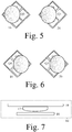
- FIG. 4 devices with direction sensors are shown.
- the first device 1 has been combined with the first direction sensor 14, and the second device 2 has been combined with the second direction sensor 24.
- a top view of the first and second devices 1 and 2 is shown, whereby the first and second devices 1 and 2 for example illuminate lanes located below the first and second devices 1 and 2 and whereby the first and second direction sensors 14 and 24 have been installed on top of the first and second devices 1 and 2, but other combinations are not to be excluded.
- the first light detector 16 forms part of the first direction sensor 14 and detects incoming light from the sun.
- This first light detector 16 comprises a first multiple field light detector with four fields Q1, Q2, Q3 and Q4, but more or fewer fields and other kinds of first light detectors are not to be excluded.
- the second light detector 26 forms part of the second direction sensor 24 and detects incoming light from the sun.
- This second light detector 26 comprises a second multiple field light detector with four fields Q1, Q2, Q3 and Q4, but more or fewer fields and other kinds of second light detectors are not to be excluded.
- the sun is located at the right side of the first and second direction sensors 16 and 26, therefore the shadows as indicated by the circles and resulting from shadow producers as discussed at the hand of the Fig. 7 are located a bit to the left.
- the field Q1 is located in the shadow to a large extent
- the fields Q2 and Q4 are located in the shadow to a medium extent
- the field Q3 is located in the shadow to a small extent.
- the field Q3 is located in the shadow to a large extent
- the fields Q2 and Q4 are located in the shadow to a medium extent
- the field Q1 is located in the shadow to a small extent.
- the first light detector 16 comprises a first multiple field light detector with four fields Q1, Q2, Q3 and Q4, but more or fewer fields and other kinds of first light detectors are not to be excluded
- the second light detector 26 comprises a second multiple field light detector with four fields Q1, Q2, Q3 and Q4, but more or fewer fields and other kinds of second light detectors are not to be excluded.
- the sun is located at the left side of the first and second direction sensors 16 and 26, therefore the shadows as indicated by the circles and resulting from shadow producers as discussed at the hand of the Fig. 7 are located a bit to the right.
- the field Q3 is located in the shadow to a large extent
- the fields Q2 and Q4 are located in the shadow to a medium extent
- the field Q1 is located in the shadow to a small extent.
- the field Q1 is located in the shadow to a large extent
- the fields Q2 and Q4 are located in the shadow to a medium extent
- the field Q3 is located in the shadow to a small extent.
- the first direction sensor 14 comprises a first light detector 16 as for example shown in the Fig. 5 and 6 , and further comprises a shadow producer 17 and an optical window 18. Through the optical window 18, the incoming light from the sun reaches those parts of the light detector 16 that are not blocked by the shadow producer 17.
- the second direction sensor 24 as shown in the Fig. 4 , a similar embodiment may be present.
- light detectors such as for example 3D light detectors that can detect incoming light angles, and such as for example cameras
- shadow producers are not to be excluded. In certain cases the shadow producers might not be necessary.
- direction sensors such as for example wind detectors and compasses, are not to be excluded too.
- each device and its direction sensor should have a predefined relationship in construction.
- the field Q1 of the first light detector 16 is - after installment - located closer to an open end of the first device 1, and the field Q3 is - after installment - located closer to the other end of the first device 1, which other end is located closest to the pole as shown in the Fig. 1 .
- the field Q1 of the second light detector 26 is - after installment - located closer to an open end of the second device 2
- the field Q3 is - after installment - located closer to the other end of the second device 2, which other end is located closest to the pole as shown in the Fig. 1 .
- one (west) device may be combined with a light detector as shown in the left parts of the Fig. 5 and 6
- another (east) device may be combined with a light detector that is, compared to the one shown in the left parts of the Fig. 5 and 6 , turned by for example 90 degrees (or any other angle different from 0 degrees).
- fully parallel devices not anti-parallel devices as shown in the Fig. 1 and 2 but really fully parallel devices
- absolute directions of the direction sensors are determined, and as a result relative directions of the devices with respect to the absolute directions of the direction sensors are determined (owing to the fact that the predefined relationships are known), and the devices to be distinguished can even have a same direction.
- FIG. 8 outputs of light detectors are shown.
- the outputs of the fields Q1-Q4 of the first light detector 16 are shown. From 10h00 to 15h00, an output of the field Q1 increases from relatively low to relatively high, an output of the field Q2 stays relatively low, an output of the field Q3 stays relatively low, and an output Q4 decreases from relatively high to relatively low.
- the outputs of the fields Q1-Q4 of the second light detector 26 are shown.
- an output of the field Q1 stays relatively low
- an output of the field Q2 decreases from relatively high to relatively low
- an output of the field Q3 increases from relatively low to relatively high
- an output Q4 stays relatively low.
- the different devices can be distinguished, and their directions can be determined.
- the Fig. 8 is not related in any way to the shadows shown in the Fig. 5 and 6 .
- the apparatus 3 can for example commission the first and second devices 1 and 2 (and many other devices if present) and can distinguish the first and second devices 1 and 2 (and the many other devices if present) from each other.
- the apparatus 3 comprises a receiver 31 for example for receiving first position information from the first position sensor 13 (possibly via the first device 1) and for example for receiving second position information from the second position sensor 23 (possibly via the second device 2) and for example for receiving first direction information from the first direction sensor 14 (possibly via the first device 1) and for example for receiving second direction information from the second direction sensor 24 (possibly via the second device 2).
- the first and second devices 1 and 2 and the apparatus 3 are coupled to the power cable 4, in which case the communication can take place via the power cable 4, but any other wired and/or wireless communication is possible too and not to be excluded.
- the first position information defines a first position of the first device 1, the second position information defines a second position of the second device 2, the first direction information defines a first direction of the first device 1 absolutely or relatively, and the second direction information defines a second direction of the second device 2 absolutely or relatively.
- These first and second directions are different directions in an absolute way or in a relative way, as discussed at the hand of the Fig. 4-7 .
- the apparatus 3 further comprises an analyzer 32 for analyzing the first and second direction information.
- the analyzer 32 might compare the outputs of the direction sensors with each other.
- the analyzer 32 might calculate functions of the outputs of the direction sensors and decide at the hand of the results, without having excluded further analyses.
- a device 1, 2 provides a temporary or non-temporary identification of itself to the apparatus 3, together with its position information and its direction information.
- the position information defines a sufficiently different position of a device
- the direction information does not need to be used.
- the position information defines insufficiently different positions of devices
- the direction information needs to be used to distinguish the devices.
- a temporary identification may be replaced by a non-temporary identification.
- a method for distinguishing first and second devices 1 and 2 from each other comprises the steps of
- the defined first and second position coordinates may then differ insufficiently to still be able to distinguish the first and second devices 1 and 2.
- Such a method may be performed in one or more of the controllers of the devices and/or in the apparatus.
- the first position information may be exchanged via a first position signal
- the second position information may be exchanged via a second position signal
- the first direction information may be exchanged via a first direction signal
- the second direction information may be exchanged via a second direction signal.
- a controller may process (analyze) one or more direction signals.
- the controller may forward one or more direction signals to another controller and/or to the apparatus.
- a receiver may receive one or more direction signals and an analyzer may analyze one or more direction signals.
- first and second positions may be absolute positions or relative positions.
- the first and second position sensors 13 and 23 may each comprise a Global Positioning System sensor or any other kind of position sensor.
- a controller may comprise any kind of processor or any other kind of controller.
- An analyzer may comprise any kind of processor or any other kind of analyzer.
- First and second units can be coupled indirectly via a third unit and can be coupled directly without the third unit being in between.
- First devices 1 comprise first drivers 11 for driving first loads 15, and first controllers 12 for controlling the first drivers 11 and for receiving first position signals from first position sensors 13 and for receiving first direction signals from first direction sensors 14.
- the first direction sensors 14 may comprise first light detectors 16.
- Apparatuses 3 may commission the devices 1, 2 and may comprise receivers 31 for receiving the position information and the direction information and analyzers 32 for analyzing the direction information to distinguish the devices 1, 2.
Landscapes
- Engineering & Computer Science (AREA)
- Radar, Positioning & Navigation (AREA)
- Remote Sensing (AREA)
- Physics & Mathematics (AREA)
- General Physics & Mathematics (AREA)
- Computer Networks & Wireless Communication (AREA)
- Electromagnetism (AREA)
- Life Sciences & Earth Sciences (AREA)
- Sustainable Development (AREA)
- Power Engineering (AREA)
- Length Measuring Devices By Optical Means (AREA)
- Circuit Arrangement For Electric Light Sources In General (AREA)
- Load-Engaging Elements For Cranes (AREA)
- Image Analysis (AREA)
- Control And Safety Of Cranes (AREA)
Applications Claiming Priority (1)
| Application Number | Priority Date | Filing Date | Title |
|---|---|---|---|
| EP15197014 | 2015-11-30 |
Publications (2)
| Publication Number | Publication Date |
|---|---|
| EP3173821A1 true EP3173821A1 (fr) | 2017-05-31 |
| EP3173821B1 EP3173821B1 (fr) | 2023-04-19 |
Family
ID=54754519
Family Applications (2)
| Application Number | Title | Priority Date | Filing Date |
|---|---|---|---|
| EP16198898.5A Active EP3173821B1 (fr) | 2015-11-30 | 2016-11-15 | Distinction de dispositifs ayant des positions et directions |
| EP16797539.0A Active EP3384316B1 (fr) | 2015-11-30 | 2016-11-16 | Distinction de dispositifs ayant des positions et directions |
Family Applications After (1)
| Application Number | Title | Priority Date | Filing Date |
|---|---|---|---|
| EP16797539.0A Active EP3384316B1 (fr) | 2015-11-30 | 2016-11-16 | Distinction de dispositifs ayant des positions et directions |
Country Status (6)
| Country | Link |
|---|---|
| US (2) | US10613186B2 (fr) |
| EP (2) | EP3173821B1 (fr) |
| JP (1) | JP7002460B2 (fr) |
| CN (1) | CN108474857B (fr) |
| ES (1) | ES2946192T3 (fr) |
| WO (1) | WO2017093017A1 (fr) |
Families Citing this family (1)
| Publication number | Priority date | Publication date | Assignee | Title |
|---|---|---|---|---|
| US10613186B2 (en) * | 2015-11-30 | 2020-04-07 | Signify Holding B.V. | Distinguishing devices having positions and directions |
Citations (5)
| Publication number | Priority date | Publication date | Assignee | Title |
|---|---|---|---|---|
| US5483060A (en) | 1992-08-19 | 1996-01-09 | Nippondenso Co., Ltd. | Optical position sensor and isolation sensor using this position sensor |
| EP0733912A2 (fr) * | 1995-03-20 | 1996-09-25 | General Electric Company | Système de localisation d'objet |
| US20090056700A1 (en) * | 2007-08-27 | 2009-03-05 | Jeffery Lin | Sun tracking system for a solar panel |
| CA2639015A1 (fr) * | 2008-08-26 | 2010-02-26 | Thomas A. La Rovere | Methode et systeme permettant de determiner l'emplacement de radiorepondeurs portatifs dans une zone geographique |
| US20150173154A1 (en) * | 2013-12-17 | 2015-06-18 | Nxp B.V. | Commissioning method and apparatus |
Family Cites Families (53)
| Publication number | Priority date | Publication date | Assignee | Title |
|---|---|---|---|---|
| US3918814A (en) | 1974-05-13 | 1975-11-11 | Weiser Robodyne Corp | Optical position sensor |
| US4320288A (en) * | 1980-04-25 | 1982-03-16 | Thermo Electron Corporation | Solar tracking system |
| US7426437B2 (en) | 1997-10-22 | 2008-09-16 | Intelligent Technologies International, Inc. | Accident avoidance systems and methods |
| US6043778A (en) * | 1997-12-29 | 2000-03-28 | Trimble Navigation Limited | Navigation system and orientation system incorporating solar sighting |
| GB0012778D0 (en) | 2000-05-26 | 2000-07-19 | Simon Anthony | Street lighting inspection |
| US20050027487A1 (en) | 2003-07-15 | 2005-02-03 | Supriya Iyer | Product defect analysis and resolution system |
| JP4354343B2 (ja) | 2004-06-15 | 2009-10-28 | 株式会社トプコン | 位置測定システム |
| US20070178967A1 (en) * | 2005-01-28 | 2007-08-02 | Outland Research, Llc | Device, system and method for football catch computer gaming |
| EP1891367B1 (fr) * | 2005-06-10 | 2017-11-15 | Lemnis Lighting Patent Holding B.V. | Systeme d'eclairage et source lumineuse a l'etat solide |
| JP4966542B2 (ja) | 2005-12-22 | 2012-07-04 | 株式会社トプコン | 位置データ補間方法及び位置測定装置 |
| RU2327952C2 (ru) | 2006-08-08 | 2008-06-27 | Олег Иванович Ермаков | Панорамный датчик угловой координаты светящегося ориентира |
| JP4914689B2 (ja) * | 2006-09-29 | 2012-04-11 | 本田技研工業株式会社 | 車両位置検出システム |
| US7566858B2 (en) * | 2006-11-07 | 2009-07-28 | Apple Inc. | Remote control systems that can distinguish stray light sources |
| GB2447264A (en) | 2007-03-05 | 2008-09-10 | Sensl Technologies Ltd | Optical position sensitive detector |
| CN101680685B (zh) | 2007-03-30 | 2012-11-14 | 亿索乐公司 | 有集成的基于图像的追踪控制器的定日镜 |
| US8102365B2 (en) * | 2007-05-14 | 2012-01-24 | Apple Inc. | Remote control systems that can distinguish stray light sources |
| US20090054077A1 (en) * | 2007-08-23 | 2009-02-26 | Telefonaktiebolaget Lm Ericsson (Publ) | Method and apparatus for sending data relating to a target to a mobile device |
| US9200901B2 (en) * | 2008-06-19 | 2015-12-01 | Microsoft Technology Licensing, Llc | Predictive services for devices supporting dynamic direction information |
| US8530817B1 (en) | 2008-10-27 | 2013-09-10 | Lockheed Martin Corporation | Field of view limit detection enhancement for quadrant-array detector systems |
| US8351546B2 (en) * | 2008-12-17 | 2013-01-08 | Aruba Networks, Inc. | Sensing device orientation in wireless networks |
| JP5142047B2 (ja) | 2009-02-26 | 2013-02-13 | アイシン・エィ・ダブリュ株式会社 | ナビゲーション装置及びナビゲーション用プログラム |
| US20100228612A1 (en) * | 2009-03-09 | 2010-09-09 | Microsoft Corporation | Device transaction model and services based on directional information of device |
| TW201042145A (en) * | 2009-05-27 | 2010-12-01 | zhen-yuan Chen | Wind-driven device |
| US8392614B2 (en) * | 2009-07-27 | 2013-03-05 | Sandisk Il Ltd. | Device identifier selection |
| US8310377B2 (en) * | 2009-08-24 | 2012-11-13 | Optotraffic, Llc | Mobile automated system for traffic monitoring |
| US10015865B2 (en) * | 2010-01-29 | 2018-07-03 | Philips Lighting Holding B.V. | Interactive lighting control system and method |
| US9572228B2 (en) * | 2010-02-18 | 2017-02-14 | Redwood Systems, Inc. | Commissioning lighting systems |
| US20130057158A1 (en) | 2010-03-01 | 2013-03-07 | Led Roadway Lighting Ltd. | Gps-based streetlight wireless command and control system |
| US20110274000A1 (en) * | 2010-05-07 | 2011-11-10 | Samsung Electronics Co., Ltd. | System and method for developing a wi-fi access point map using sensors in a wireless mobile device |
| KR101658908B1 (ko) * | 2010-05-17 | 2016-09-30 | 삼성전자주식회사 | 휴대용 단말기에서 통화 음질을 개선하기 위한 장치 및 방법 |
| US8433759B2 (en) * | 2010-05-24 | 2013-04-30 | Sony Computer Entertainment America Llc | Direction-conscious information sharing |
| US8593398B2 (en) * | 2010-06-25 | 2013-11-26 | Nokia Corporation | Apparatus and method for proximity based input |
| US9341720B2 (en) | 2011-01-11 | 2016-05-17 | Qualcomm Incorporated | Camera-based position location and navigation based on image processing |
| US8901825B2 (en) * | 2011-04-12 | 2014-12-02 | Express Imaging Systems, Llc | Apparatus and method of energy efficient illumination using received signals |
| US9366749B2 (en) * | 2011-04-15 | 2016-06-14 | Qualcomm Incorporated | Device position estimates from motion and ambient light classifiers |
| US9014632B2 (en) * | 2011-04-29 | 2015-04-21 | Here Global B.V. | Obtaining vehicle traffic information using mobile bluetooth detectors |
| US9041556B2 (en) * | 2011-10-20 | 2015-05-26 | Apple Inc. | Method for locating a vehicle |
| US9231141B2 (en) * | 2012-12-14 | 2016-01-05 | International Business Machines Corporation | Controlling a solar tracking system |
| EP3014248B1 (fr) * | 2013-06-26 | 2020-08-05 | Signify Holding B.V. | Appareil et procédé employant des luminaires à base de capteurs pour détecter des zones de visibilité réduite et leur sens de déplacement |
| CN105874883B (zh) * | 2013-09-10 | 2019-06-18 | 飞利浦灯具控股公司 | 用于编码光源的自动化投用的方法和装置 |
| US20150136944A1 (en) * | 2013-11-21 | 2015-05-21 | Avraham Segev | Sunlight tracking sensor and system |
| CN103728986B (zh) * | 2013-11-29 | 2017-01-18 | 深圳市华星光电技术有限公司 | 太阳光收集装置及太阳光追踪方法 |
| DE102013225927A1 (de) * | 2013-12-13 | 2015-07-02 | Siemens Aktiengesellschaft | Vorrichtung und Verfahren zum Handhaben von Gegenständen |
| US9549290B2 (en) * | 2013-12-19 | 2017-01-17 | Google Technology Holdings LLC | Method and apparatus for determining direction information for a wireless device |
| EP3120069B1 (fr) | 2014-03-21 | 2022-05-11 | Signify Holding B.V. | Mise en service de dispositifs d'éclairage intelligents gérés à distance |
| JP6369258B2 (ja) * | 2014-09-22 | 2018-08-08 | カシオ計算機株式会社 | 商品登録装置、商品登録方法およびプログラム |
| EP3215864B1 (fr) * | 2014-11-07 | 2020-07-29 | Sony Corporation | Détermination d'emplacement géographique de dispositif électronique portable à l'aide d'un réseau d'antennes synthétiques |
| US20160260328A1 (en) * | 2015-03-06 | 2016-09-08 | Qualcomm Incorporated | Real-time Occupancy Mapping System for Autonomous Vehicles |
| US9625582B2 (en) * | 2015-03-25 | 2017-04-18 | Google Inc. | Vehicle with multiple light detection and ranging devices (LIDARs) |
| KR20170051651A (ko) * | 2015-10-30 | 2017-05-12 | 삼성전자주식회사 | 조명 시스템, 조명 제어 장치 및 제어 방법 |
| US10613186B2 (en) * | 2015-11-30 | 2020-04-07 | Signify Holding B.V. | Distinguishing devices having positions and directions |
| KR102482595B1 (ko) * | 2015-12-17 | 2022-12-30 | 삼성전자주식회사 | 지도 정보 제공 방법 및 이를 지원하는 전자 장치 |
| US10390183B2 (en) * | 2017-02-24 | 2019-08-20 | Lsi Industries, Inc. | Light fixture positioning system that transmits beacon signals having different spatial resolutions |
-
2016
- 2016-11-15 US US15/352,413 patent/US10613186B2/en active Active
- 2016-11-15 ES ES16198898T patent/ES2946192T3/es active Active
- 2016-11-15 EP EP16198898.5A patent/EP3173821B1/fr active Active
- 2016-11-16 EP EP16797539.0A patent/EP3384316B1/fr active Active
- 2016-11-16 WO PCT/EP2016/077793 patent/WO2017093017A1/fr active Application Filing
- 2016-11-16 CN CN201680069986.5A patent/CN108474857B/zh active Active
- 2016-11-16 JP JP2018546748A patent/JP7002460B2/ja active Active
- 2016-11-16 US US15/778,849 patent/US10895624B2/en active Active
Patent Citations (5)
| Publication number | Priority date | Publication date | Assignee | Title |
|---|---|---|---|---|
| US5483060A (en) | 1992-08-19 | 1996-01-09 | Nippondenso Co., Ltd. | Optical position sensor and isolation sensor using this position sensor |
| EP0733912A2 (fr) * | 1995-03-20 | 1996-09-25 | General Electric Company | Système de localisation d'objet |
| US20090056700A1 (en) * | 2007-08-27 | 2009-03-05 | Jeffery Lin | Sun tracking system for a solar panel |
| CA2639015A1 (fr) * | 2008-08-26 | 2010-02-26 | Thomas A. La Rovere | Methode et systeme permettant de determiner l'emplacement de radiorepondeurs portatifs dans une zone geographique |
| US20150173154A1 (en) * | 2013-12-17 | 2015-06-18 | Nxp B.V. | Commissioning method and apparatus |
Also Published As
| Publication number | Publication date |
|---|---|
| EP3384316A1 (fr) | 2018-10-10 |
| ES2946192T3 (es) | 2023-07-13 |
| CN108474857A (zh) | 2018-08-31 |
| US10895624B2 (en) | 2021-01-19 |
| JP2018536880A (ja) | 2018-12-13 |
| US20170153311A1 (en) | 2017-06-01 |
| EP3384316B1 (fr) | 2021-06-16 |
| EP3173821B1 (fr) | 2023-04-19 |
| JP7002460B2 (ja) | 2022-01-20 |
| US20180348330A1 (en) | 2018-12-06 |
| US10613186B2 (en) | 2020-04-07 |
| CN108474857B (zh) | 2022-08-12 |
| WO2017093017A1 (fr) | 2017-06-08 |
Similar Documents
| Publication | Publication Date | Title |
|---|---|---|
| US9020666B2 (en) | Taking-off and landing target instrument and automatic taking-off and landing system | |
| CN105940316B (zh) | 传感器设备 | |
| EP2789974B1 (fr) | Système de surveillance | |
| US20140198206A1 (en) | System and Method for Estimating the Position and Orientation of an Object using Optical Beacons | |
| US9712234B1 (en) | Location aware communication system using visible light transmission | |
| KR101558060B1 (ko) | 가시광 통신 기반 실내 위치 인식 시스템, 실내 네비게이션 방법, 실내 네비게이션 시스템, 실내 네비게이션을 수행하는 서버 및 전자 기기 | |
| US9892638B2 (en) | Lighting unit, fixture and newtork | |
| US10067233B2 (en) | Illuminance measuring system | |
| US10057727B2 (en) | Indoor positioning system based on motion sensing augmented with beacons | |
| EP3111163A1 (fr) | Estimation de position de source de lumière d'un luminaire à partir d'une empreinte de lumière | |
| US10215839B2 (en) | Pose detection device of movable body and location-based supplemental service providing system | |
| JP2013185851A (ja) | 測位装置、該測位装置を備えた測位システム、及び測位方法 | |
| US10613186B2 (en) | Distinguishing devices having positions and directions | |
| CN114252884A (zh) | 路侧雷达定位监测方法、装置、计算机设备和存储介质 | |
| CN106092068B (zh) | 不对中导线测量待测点坐标的测量系统及测量方法 | |
| CN202422153U (zh) | 一种视频检测人体数量和位置及其移动的装置 | |
| KR20170037981A (ko) | 센서의 위치 및/또는 방향을 결정하는 방법 | |
| WO2019025382A1 (fr) | Dispositif électronique, procédé et programme informatique pour déterminer et utiliser une distance en fonction d'informations de constellation correspondantes | |
| CN104103902A (zh) | 基于指北针和坡度仪的点到点的对准方法 | |
| CN113643367A (zh) | 基于增强现实的室内定位方法及系统 | |
| Soloiu et al. | Optimizing Color Detection with Robotic Vision Sensors for Lane Following and Traffic Sign Recognition in Small Scale Autonomous Test Vehicles |
Legal Events
| Date | Code | Title | Description |
|---|---|---|---|
| PUAI | Public reference made under article 153(3) epc to a published international application that has entered the european phase |
Free format text: ORIGINAL CODE: 0009012 |
|
| STAA | Information on the status of an ep patent application or granted ep patent |
Free format text: STATUS: THE APPLICATION HAS BEEN PUBLISHED |
|
| AK | Designated contracting states |
Kind code of ref document: A1 Designated state(s): AL AT BE BG CH CY CZ DE DK EE ES FI FR GB GR HR HU IE IS IT LI LT LU LV MC MK MT NL NO PL PT RO RS SE SI SK SM TR |
|
| AX | Request for extension of the european patent |
Extension state: BA ME |
|
| STAA | Information on the status of an ep patent application or granted ep patent |
Free format text: STATUS: REQUEST FOR EXAMINATION WAS MADE |
|
| 17P | Request for examination filed |
Effective date: 20171130 |
|
| RBV | Designated contracting states (corrected) |
Designated state(s): AL AT BE BG CH CY CZ DE DK EE ES FI FR GB GR HR HU IE IS IT LI LT LU LV MC MK MT NL NO PL PT RO RS SE SI SK SM TR |
|
| RAP1 | Party data changed (applicant data changed or rights of an application transferred) |
Owner name: PHILIPS LIGHTING HOLDING B.V. |
|
| RAP1 | Party data changed (applicant data changed or rights of an application transferred) |
Owner name: SIGNIFY HOLDING B.V. |
|
| STAA | Information on the status of an ep patent application or granted ep patent |
Free format text: STATUS: EXAMINATION IS IN PROGRESS |
|
| 17Q | First examination report despatched |
Effective date: 20200423 |
|
| STAA | Information on the status of an ep patent application or granted ep patent |
Free format text: STATUS: EXAMINATION IS IN PROGRESS |
|
| GRAP | Despatch of communication of intention to grant a patent |
Free format text: ORIGINAL CODE: EPIDOSNIGR1 |
|
| STAA | Information on the status of an ep patent application or granted ep patent |
Free format text: STATUS: GRANT OF PATENT IS INTENDED |
|
| INTG | Intention to grant announced |
Effective date: 20221108 |
|
| GRAS | Grant fee paid |
Free format text: ORIGINAL CODE: EPIDOSNIGR3 |
|
| GRAA | (expected) grant |
Free format text: ORIGINAL CODE: 0009210 |
|
| STAA | Information on the status of an ep patent application or granted ep patent |
Free format text: STATUS: THE PATENT HAS BEEN GRANTED |
|
| AK | Designated contracting states |
Kind code of ref document: B1 Designated state(s): AL AT BE BG CH CY CZ DE DK EE ES FI FR GB GR HR HU IE IS IT LI LT LU LV MC MK MT NL NO PL PT RO RS SE SI SK SM TR |
|
| REG | Reference to a national code |
Ref country code: GB Ref legal event code: FG4D |
|
| REG | Reference to a national code |
Ref country code: CH Ref legal event code: EP |
|
| REG | Reference to a national code |
Ref country code: DE Ref legal event code: R096 Ref document number: 602016078875 Country of ref document: DE |
|
| REG | Reference to a national code |
Ref country code: IE Ref legal event code: FG4D |
|
| REG | Reference to a national code |
Ref country code: AT Ref legal event code: REF Ref document number: 1561606 Country of ref document: AT Kind code of ref document: T Effective date: 20230515 |
|
| P01 | Opt-out of the competence of the unified patent court (upc) registered |
Effective date: 20230530 |
|
| REG | Reference to a national code |
Ref country code: ES Ref legal event code: FG2A Ref document number: 2946192 Country of ref document: ES Kind code of ref document: T3 Effective date: 20230713 |
|
| REG | Reference to a national code |
Ref country code: LT Ref legal event code: MG9D |
|
| REG | Reference to a national code |
Ref country code: NL Ref legal event code: MP Effective date: 20230419 |
|
| REG | Reference to a national code |
Ref country code: AT Ref legal event code: MK05 Ref document number: 1561606 Country of ref document: AT Kind code of ref document: T Effective date: 20230419 |
|
| PG25 | Lapsed in a contracting state [announced via postgrant information from national office to epo] |
Ref country code: NL Free format text: LAPSE BECAUSE OF FAILURE TO SUBMIT A TRANSLATION OF THE DESCRIPTION OR TO PAY THE FEE WITHIN THE PRESCRIBED TIME-LIMIT Effective date: 20230419 |
|
| PG25 | Lapsed in a contracting state [announced via postgrant information from national office to epo] |
Ref country code: SE Free format text: LAPSE BECAUSE OF FAILURE TO SUBMIT A TRANSLATION OF THE DESCRIPTION OR TO PAY THE FEE WITHIN THE PRESCRIBED TIME-LIMIT Effective date: 20230419 Ref country code: PT Free format text: LAPSE BECAUSE OF FAILURE TO SUBMIT A TRANSLATION OF THE DESCRIPTION OR TO PAY THE FEE WITHIN THE PRESCRIBED TIME-LIMIT Effective date: 20230821 Ref country code: NO Free format text: LAPSE BECAUSE OF FAILURE TO SUBMIT A TRANSLATION OF THE DESCRIPTION OR TO PAY THE FEE WITHIN THE PRESCRIBED TIME-LIMIT Effective date: 20230719 Ref country code: AT Free format text: LAPSE BECAUSE OF FAILURE TO SUBMIT A TRANSLATION OF THE DESCRIPTION OR TO PAY THE FEE WITHIN THE PRESCRIBED TIME-LIMIT Effective date: 20230419 |
|
| PG25 | Lapsed in a contracting state [announced via postgrant information from national office to epo] |
Ref country code: RS Free format text: LAPSE BECAUSE OF FAILURE TO SUBMIT A TRANSLATION OF THE DESCRIPTION OR TO PAY THE FEE WITHIN THE PRESCRIBED TIME-LIMIT Effective date: 20230419 Ref country code: PL Free format text: LAPSE BECAUSE OF FAILURE TO SUBMIT A TRANSLATION OF THE DESCRIPTION OR TO PAY THE FEE WITHIN THE PRESCRIBED TIME-LIMIT Effective date: 20230419 Ref country code: LV Free format text: LAPSE BECAUSE OF FAILURE TO SUBMIT A TRANSLATION OF THE DESCRIPTION OR TO PAY THE FEE WITHIN THE PRESCRIBED TIME-LIMIT Effective date: 20230419 Ref country code: LT Free format text: LAPSE BECAUSE OF FAILURE TO SUBMIT A TRANSLATION OF THE DESCRIPTION OR TO PAY THE FEE WITHIN THE PRESCRIBED TIME-LIMIT Effective date: 20230419 Ref country code: IS Free format text: LAPSE BECAUSE OF FAILURE TO SUBMIT A TRANSLATION OF THE DESCRIPTION OR TO PAY THE FEE WITHIN THE PRESCRIBED TIME-LIMIT Effective date: 20230819 Ref country code: HR Free format text: LAPSE BECAUSE OF FAILURE TO SUBMIT A TRANSLATION OF THE DESCRIPTION OR TO PAY THE FEE WITHIN THE PRESCRIBED TIME-LIMIT Effective date: 20230419 Ref country code: GR Free format text: LAPSE BECAUSE OF FAILURE TO SUBMIT A TRANSLATION OF THE DESCRIPTION OR TO PAY THE FEE WITHIN THE PRESCRIBED TIME-LIMIT Effective date: 20230720 Ref country code: AL Free format text: LAPSE BECAUSE OF FAILURE TO SUBMIT A TRANSLATION OF THE DESCRIPTION OR TO PAY THE FEE WITHIN THE PRESCRIBED TIME-LIMIT Effective date: 20230419 |
|
| PG25 | Lapsed in a contracting state [announced via postgrant information from national office to epo] |
Ref country code: FI Free format text: LAPSE BECAUSE OF FAILURE TO SUBMIT A TRANSLATION OF THE DESCRIPTION OR TO PAY THE FEE WITHIN THE PRESCRIBED TIME-LIMIT Effective date: 20230419 |
|
| PG25 | Lapsed in a contracting state [announced via postgrant information from national office to epo] |
Ref country code: SK Free format text: LAPSE BECAUSE OF FAILURE TO SUBMIT A TRANSLATION OF THE DESCRIPTION OR TO PAY THE FEE WITHIN THE PRESCRIBED TIME-LIMIT Effective date: 20230419 |
|
| PGFP | Annual fee paid to national office [announced via postgrant information from national office to epo] |
Ref country code: GB Payment date: 20231121 Year of fee payment: 8 |
|
| PGFP | Annual fee paid to national office [announced via postgrant information from national office to epo] |
Ref country code: ES Payment date: 20231218 Year of fee payment: 8 |
|
| REG | Reference to a national code |
Ref country code: DE Ref legal event code: R097 Ref document number: 602016078875 Country of ref document: DE |
|
| PG25 | Lapsed in a contracting state [announced via postgrant information from national office to epo] |
Ref country code: SM Free format text: LAPSE BECAUSE OF FAILURE TO SUBMIT A TRANSLATION OF THE DESCRIPTION OR TO PAY THE FEE WITHIN THE PRESCRIBED TIME-LIMIT Effective date: 20230419 Ref country code: SK Free format text: LAPSE BECAUSE OF FAILURE TO SUBMIT A TRANSLATION OF THE DESCRIPTION OR TO PAY THE FEE WITHIN THE PRESCRIBED TIME-LIMIT Effective date: 20230419 Ref country code: RO Free format text: LAPSE BECAUSE OF FAILURE TO SUBMIT A TRANSLATION OF THE DESCRIPTION OR TO PAY THE FEE WITHIN THE PRESCRIBED TIME-LIMIT Effective date: 20230419 Ref country code: EE Free format text: LAPSE BECAUSE OF FAILURE TO SUBMIT A TRANSLATION OF THE DESCRIPTION OR TO PAY THE FEE WITHIN THE PRESCRIBED TIME-LIMIT Effective date: 20230419 Ref country code: DK Free format text: LAPSE BECAUSE OF FAILURE TO SUBMIT A TRANSLATION OF THE DESCRIPTION OR TO PAY THE FEE WITHIN THE PRESCRIBED TIME-LIMIT Effective date: 20230419 Ref country code: CZ Free format text: LAPSE BECAUSE OF FAILURE TO SUBMIT A TRANSLATION OF THE DESCRIPTION OR TO PAY THE FEE WITHIN THE PRESCRIBED TIME-LIMIT Effective date: 20230419 |
|
| PGFP | Annual fee paid to national office [announced via postgrant information from national office to epo] |
Ref country code: IT Payment date: 20231124 Year of fee payment: 8 Ref country code: FR Payment date: 20231123 Year of fee payment: 8 |
|
| PLBE | No opposition filed within time limit |
Free format text: ORIGINAL CODE: 0009261 |
|
| STAA | Information on the status of an ep patent application or granted ep patent |
Free format text: STATUS: NO OPPOSITION FILED WITHIN TIME LIMIT |
|
| 26N | No opposition filed |
Effective date: 20240122 |
|
| PGFP | Annual fee paid to national office [announced via postgrant information from national office to epo] |
Ref country code: DE Payment date: 20240129 Year of fee payment: 8 |
|
| PG25 | Lapsed in a contracting state [announced via postgrant information from national office to epo] |
Ref country code: SI Free format text: LAPSE BECAUSE OF FAILURE TO SUBMIT A TRANSLATION OF THE DESCRIPTION OR TO PAY THE FEE WITHIN THE PRESCRIBED TIME-LIMIT Effective date: 20230419 |