EP3173754B1 - Spektroskopievorrichtung mit bragg-gitter - Google Patents
Spektroskopievorrichtung mit bragg-gitter Download PDFInfo
- Publication number
- EP3173754B1 EP3173754B1 EP16182955.1A EP16182955A EP3173754B1 EP 3173754 B1 EP3173754 B1 EP 3173754B1 EP 16182955 A EP16182955 A EP 16182955A EP 3173754 B1 EP3173754 B1 EP 3173754B1
- Authority
- EP
- European Patent Office
- Prior art keywords
- core member
- refractive
- bragg grating
- width
- resonator
- Prior art date
- Legal status (The legal status is an assumption and is not a legal conclusion. Google has not performed a legal analysis and makes no representation as to the accuracy of the status listed.)
- Active
Links
Images




Classifications
-
- G—PHYSICS
- G01—MEASURING; TESTING
- G01J—MEASUREMENT OF INTENSITY, VELOCITY, SPECTRAL CONTENT, POLARISATION, PHASE OR PULSE CHARACTERISTICS OF INFRARED, VISIBLE OR ULTRAVIOLET LIGHT; COLORIMETRY; RADIATION PYROMETRY
- G01J3/00—Spectrometry; Spectrophotometry; Monochromators; Measuring colours
- G01J3/12—Generating the spectrum; Monochromators
- G01J3/18—Generating the spectrum; Monochromators using diffraction elements, e.g. grating
- G01J3/1895—Generating the spectrum; Monochromators using diffraction elements, e.g. grating using fiber Bragg gratings or gratings integrated in a waveguide
-
- G—PHYSICS
- G02—OPTICS
- G02B—OPTICAL ELEMENTS, SYSTEMS OR APPARATUS
- G02B5/00—Optical elements other than lenses
- G02B5/18—Diffraction gratings
- G02B5/1861—Reflection gratings characterised by their structure, e.g. step profile, contours of substrate or grooves, pitch variations, materials
-
- G—PHYSICS
- G02—OPTICS
- G02B—OPTICAL ELEMENTS, SYSTEMS OR APPARATUS
- G02B6/00—Light guides; Structural details of arrangements comprising light guides and other optical elements, e.g. couplings
- G02B6/02—Optical fibres with cladding with or without a coating
- G02B6/02057—Optical fibres with cladding with or without a coating comprising gratings
- G02B6/02076—Refractive index modulation gratings, e.g. Bragg gratings
-
- G—PHYSICS
- G02—OPTICS
- G02B—OPTICAL ELEMENTS, SYSTEMS OR APPARATUS
- G02B6/00—Light guides; Structural details of arrangements comprising light guides and other optical elements, e.g. couplings
- G02B6/10—Light guides; Structural details of arrangements comprising light guides and other optical elements, e.g. couplings of the optical waveguide type
- G02B6/12—Light guides; Structural details of arrangements comprising light guides and other optical elements, e.g. couplings of the optical waveguide type of the integrated circuit kind
- G02B6/122—Basic optical elements, e.g. light-guiding paths
- G02B6/124—Geodesic lenses or integrated gratings
-
- G—PHYSICS
- G02—OPTICS
- G02B—OPTICAL ELEMENTS, SYSTEMS OR APPARATUS
- G02B6/00—Light guides; Structural details of arrangements comprising light guides and other optical elements, e.g. couplings
- G02B6/24—Coupling light guides
- G02B6/26—Optical coupling means
- G02B6/28—Optical coupling means having data bus means, i.e. plural waveguides interconnected and providing an inherently bidirectional system by mixing and splitting signals
- G02B6/293—Optical coupling means having data bus means, i.e. plural waveguides interconnected and providing an inherently bidirectional system by mixing and splitting signals with wavelength selective means
- G02B6/29304—Optical coupling means having data bus means, i.e. plural waveguides interconnected and providing an inherently bidirectional system by mixing and splitting signals with wavelength selective means operating by diffraction, e.g. grating
- G02B6/29316—Light guides comprising a diffractive element, e.g. grating in or on the light guide such that diffracted light is confined in the light guide
-
- G—PHYSICS
- G02—OPTICS
- G02B—OPTICAL ELEMENTS, SYSTEMS OR APPARATUS
- G02B6/00—Light guides; Structural details of arrangements comprising light guides and other optical elements, e.g. couplings
- G02B6/24—Coupling light guides
- G02B6/26—Optical coupling means
- G02B6/28—Optical coupling means having data bus means, i.e. plural waveguides interconnected and providing an inherently bidirectional system by mixing and splitting signals
- G02B6/293—Optical coupling means having data bus means, i.e. plural waveguides interconnected and providing an inherently bidirectional system by mixing and splitting signals with wavelength selective means
- G02B6/29346—Optical coupling means having data bus means, i.e. plural waveguides interconnected and providing an inherently bidirectional system by mixing and splitting signals with wavelength selective means operating by wave or beam interference
- G02B6/29356—Interference cavity within a single light guide, e.g. between two fibre gratings
-
- G—PHYSICS
- G02—OPTICS
- G02B—OPTICAL ELEMENTS, SYSTEMS OR APPARATUS
- G02B6/00—Light guides; Structural details of arrangements comprising light guides and other optical elements, e.g. couplings
- G02B6/24—Coupling light guides
- G02B6/26—Optical coupling means
- G02B6/28—Optical coupling means having data bus means, i.e. plural waveguides interconnected and providing an inherently bidirectional system by mixing and splitting signals
- G02B6/293—Optical coupling means having data bus means, i.e. plural waveguides interconnected and providing an inherently bidirectional system by mixing and splitting signals with wavelength selective means
- G02B6/29379—Optical coupling means having data bus means, i.e. plural waveguides interconnected and providing an inherently bidirectional system by mixing and splitting signals with wavelength selective means characterised by the function or use of the complete device
- G02B6/29389—Bandpass filtering, e.g. 1x1 device rejecting or passing certain wavelengths
-
- G—PHYSICS
- G01—MEASURING; TESTING
- G01J—MEASUREMENT OF INTENSITY, VELOCITY, SPECTRAL CONTENT, POLARISATION, PHASE OR PULSE CHARACTERISTICS OF INFRARED, VISIBLE OR ULTRAVIOLET LIGHT; COLORIMETRY; RADIATION PYROMETRY
- G01J3/00—Spectrometry; Spectrophotometry; Monochromators; Measuring colours
- G01J3/12—Generating the spectrum; Monochromators
- G01J3/18—Generating the spectrum; Monochromators using diffraction elements, e.g. grating
- G01J2003/1842—Types of grating
- G01J2003/1847—Variable spacing
-
- G—PHYSICS
- G02—OPTICS
- G02B—OPTICAL ELEMENTS, SYSTEMS OR APPARATUS
- G02B6/00—Light guides; Structural details of arrangements comprising light guides and other optical elements, e.g. couplings
- G02B6/24—Coupling light guides
- G02B6/26—Optical coupling means
- G02B6/28—Optical coupling means having data bus means, i.e. plural waveguides interconnected and providing an inherently bidirectional system by mixing and splitting signals
- G02B6/293—Optical coupling means having data bus means, i.e. plural waveguides interconnected and providing an inherently bidirectional system by mixing and splitting signals with wavelength selective means
- G02B6/29304—Optical coupling means having data bus means, i.e. plural waveguides interconnected and providing an inherently bidirectional system by mixing and splitting signals with wavelength selective means operating by diffraction, e.g. grating
- G02B6/29316—Light guides comprising a diffractive element, e.g. grating in or on the light guide such that diffracted light is confined in the light guide
- G02B6/29325—Light guides comprising a diffractive element, e.g. grating in or on the light guide such that diffracted light is confined in the light guide of the slab or planar or plate like form, i.e. confinement in a single transverse dimension only
- G02B6/29328—Diffractive elements operating in reflection
Definitions
- the invention relates to a spectrometer including a Bragg grating.
- Biometric technology on wearable devices allows users to measure biometric information such as blood glucose in a non-invasive manner.
- the size of the spectrometer may have to be ultra-small to fit in the wearable devices.
- Fabry-Pero interferometers having different lengths as a chip by using silicon (Si)-photonics technology, an ultra-small size spectrometer may be manufactured.
- a Fabry-Perot interferometer includes a resonator and Bragg gratings at opposite end portions of the resonator. An important factor is to manufacture a Bragg grating having high reflectivity on the desired wavelength range of a wearable device.
- the invention provides a spectrometer according to claim 1, comprising a resonator comprising a waveguide, and a Bragg grating disposed at one or each of opposite ends of the resonator for reflecting light of a certain wavelength band including: a core member extending from the waveguide of the resonator in a lengthwise direction of the waveguide; a plurality of first refractive members protruding from the core member and spaced apart from each other along the lengthwise direction; and a second refractive member filling spaces between the first refractive members and having a refractive index different from a refractive index of the first refractive members.
- the first refractive members protrude from opposite sides of the core member in a width direction of the core member. At least some of pitches (spatial intervals) between the first refractive members vary along the lengthwise direction.
- the width of the core member gradually reduces toward a center portion of the core member along the lengthwise direction.
- the protruding lengths of the first refractive members gradually increase toward the center portion of the core member along the lengthwise direction.
- the first refractive members may face each other across on the core member.
- the width of the core member is less than a width of the waveguide in the resonator.
- Each of the core member and the first refractive members may include silicon nitride.
- the second refractive member may include silicon oxide.
- the spectrometer comprises a Bragg grating as described above at one of the two different ends of the resonator and another Bragg grating as described above at the other of the two different ends of the resonator.
- the second refractive member may cover the waveguide of the resonator, the core member, and the plurality of first refractive members.
- the spectroscopy units may be on a silicon substrate.
- a component such as a layer, a film, a region, or a plate
- the component may be directly on the other component or intervening components may be present thereon.
- materials forming each layer in exemplary embodiments are examples, and thus, other materials than the examples below may be used.
- the term "and/or" includes any and all combinations of one or more of the associated listed items. Expressions such as "at least one of,” when preceding a list of elements, modify the entire list of elements and do not modify the individual elements of the list.
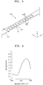
- FIG. 1 is a perspective view of a Fabry-Perot interferometer 100 having a general structure
- FIG. 2 is a cross-sectional view of the Fabry-Perot interferometer 100 of FIG. 1
- FIG. 3 is a perspective view of a Bragg grating 120 shown in FIG. 1 .
- the Fabry-Perot interferometer 100 may include a resonator 110 having a waveguide 111 of a predetermined length, and Bragg gratings 120 at opposite ends of the resonator 110.
- the waveguide 111 of the resonator 110 may include, for example, silicon nitride.
- the Bragg grating 120 may reflect light of a predetermined wavelength band.
- the Bragg grating 120 may include a plurality of first refractive members 121 arranged in a lengthwise direction (e.g., x-direction in FIG. 1 ) of the resonator 110, and a second refractive member 122 filling spaces between the first refractive members 121.
- a width W of the Bragg grating 120 in a y-direction may be equal to a width D of the waveguide 111 in the y-direction of the resonator 110.
- the first refractive members 121 may have a refractive index different from a refractive index of the second refractive member 122.
- the first refractive members 121 may include silicon nitride
- the second refractive member 122 may include silicon oxide.
- the second refractive member 122 may cover the waveguide 111 of the resonator 110 and the Bragg gratings 120.
- the first refractive members 121 are spaced apart from each other along the lengthwise direction of the resonator 110. Intervals between the first refractive members 121, that is, pitches P between the first refractive members 121, may be constant along the lengthwise direction of the Bragg grating 120.
- the Bragg grating 120 having the above structure materials having different refractive indexes, for example, the first refractive members 121 including the silicon nitride and the second refractive member 122 including silicon oxide are disposed, and the first and second refractive members are formed and arranged to create an interference pattern between waves.
- the Bragg grating 120 having the above structure may reflect particular wavelengths of light and have a high reflectivity at the particular wavelengths. However, the Bragg grating 120 may not have a high reflectivity with respect to a wide wavelength band.
- FIG. 4 is a graph of reflectivity of the Bragg grating 120 of FIG. 3 with respect to a wavelength band of 800 nm to 900 nm.
- the first refractive members 121 and the second refractive member 122 forming the Bragg grating 120 respectively include silicon nitride and silicon oxide, and pitches P between the first refractive members 121 are 290 nm.
- reflectivity is very low, that is, 20% or less. Therefore, it is difficult to obtain high reflectivity with respect to the wavelength band of 800 nm to 830 nm by using the Bragg grating 120 of FIG. 3 .
- an ultra-small size spectroscopy device that is to be implemented as a wearable device has to use a wavelength band having a width of 100 nm or greater, and thus, the Bragg grating 120 having the above described structure may not be suitable for the ultra-small size spectroscopy device.
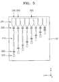
- FIG. 5 is a plan view of a spectroscopy device according to an exemplary embodiment.
- the spectroscopy device includes a plurality of spectroscopy units 200 provided on a substrate 201.
- the substrate 201 may be, for example, a silicon substrate, but is not limited thereto.
- each of the spectroscopy units 200 may include a Fabry-Perot interferometer, but the exemplary embodiment is not limited thereto.
- Each of the spectroscopy units 200 may include a resonator 210, and Bragg gratings (e.g., reflector) 220 provided at opposite ends of the resonator 210.
- the Bragg grating 220 provided at a first end of the resonator 210 may be connected to an input coupler 231, through which light is incident, and the Bragg grating 210 provided at a second end of the resonator 210 may be connected to an output coupler 232 through which light is emitted.
- the first end of the resonator 210 may oppose the second end of the resonator 210.
- At least some of the spectroscopy units 200 may include resonators 210 having different lengths from each other.
- a sequence of the spectroscopy units 200 are arranged in a y-direction, and the lengths of the resonators 210 of the spectroscopy units 200 gradually increase along the y-direction.
- the spectroscopy device having the above structure may be integrated on, for example, a silicon substrate, to be manufactured as a fine chip.
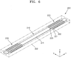
- FIG. 6 is a perspective view of the spectroscopy unit 200 of FIG. 5 .
- the spectroscopy unit 200 includes the resonator 210 having a predetermined length and the Bragg gratings 220 at opposite ends of the resonator 210.
- the resonator 210 may include a waveguide 211 including a predetermined medium for making light proceed therein.
- the waveguide 211 may have a thickness of about 100 nm to 200 nm and a width D of about 200 nm to about 900 nm, for example.
- the exemplary embodiment is not limited thereto, that is, the thickness and the width of the waveguide 211 may vary.
- the waveguide 211 may include, for example, silicon nitride, but is not limited thereto, that is, the waveguide 211 may include other various materials.
- FIG. 7 is an internal plan view of the Bragg grating 220 of FIG. 6 .
- the Bragg grating 220 includes a core member 223, a plurality of first refractive members 221, and a second refractive member 222.
- the core member 223 may extend from the waveguide 211 of the resonator 210 in a lengthwise direction (i.e., x-direction of FIG. 7 ).
- the core member 223 may be integrally formed with the waveguide 211 of the resonator 210.
- the core member 223 may include the same material as that included in the waveguide 211 of the resonator 210.
- the core member 223 may include silicon nitride, but is not limited thereto. Otherwise, the core member 223 may include a different material from that of the waveguide 211 of the resonator 210.
- the first refractive members 221 may protrude from the core member 223.
- the first refractive members 221 may include a plurality of pairs of arms. Each pair of arms extends outwardly from the core member 223 to be in parallel to each other and perpendicular to the core member 223.
- the core member 223 may hold the plurality of pairs of arms in fixed positions on the core member 223.
- the first refractive members 221 may protrude from opposite sides of the core member 223 in a width direction of the core member 223 (i.e., y-direction in FIG. 7 ).
- the first refractive members 221 may be spaced apart from each other in the lengthwise direction of the core member 223.
- the first refractive members 221 may face each other across the core member 223 when viewed from the top of the spectroscopy unit 200, but are not limited thereto.
- the first refractive members 221 may be integrally formed with the core member 223.
- the first refractive members 221 may include the same material as that of the core member 223.
- the first refractive members 221 may include silicon nitride, but are not limited thereto.
- the second refractive member 222 is provided to fill spaces between the first refractive members 221.
- the second refractive member 222 may include a material having a refractive index that is different from those of the first refractive members 221.
- the second refractive member 222 may include silicon oxide, but is not limited thereto.
- the second refractive member 222 may be provided to cover the waveguide 211 of the resonator 210 and the first refractive members 221.
- a width W1 of the Bragg grating 220 may be greater than the width D of the waveguide 211 of the resonator 210.
- the width W1 may be also referred to as a span of the Bragg grating 220.
- a width W2 of the core member 223 may be less than the width D of the waveguide 211 of the resonator 210.
- the width W1 of the Bragg grating 220 may correspond to a sum of protruding lengths L of the two first refractive members 221 that protrude toward opposite directions and the width W2 of the core member 223.
- the width W1 of the Bragg grating 220 and the width W2 of the core member 223 may be constant along the lengthwise direction of the core member 223. Accordingly, the protruding lengths L of the first refractive members 221 may be constant along the lengthwise direction of the core member 223.
- FIG. 8 is a graph of reflectivity of the Bragg grating 220 of FIG. 7 with respect to a wavelength band of 800 nm to 900 nm.
- the first refractive members 221 and the second refractive member 222 included in the Bragg grating 220 respectively include silicon nitride and silicon oxide, and pitches P between the first refractive members 221 are 290 nm.
- the width D of the waveguide 211, the width W1 of the Bragg grating 220, and the width W2 of the core member 223 are respectively 510 nm, 1000 nm, and 200 nm.
- the Bragg grating 220 of FIG. 7 may achieve higher reflectivity than the Bragg grating 120 of FIG. 3 .
- the Bragg grating 120 exhibits low reflectivity with respect to the wavelength band of 800 nm to 830 nm.
- the Bragg grating 220 of FIG. 7 exhibits high reflectivity with respect to the wavelength band of 800 nm to 830 nm, as well.
- the Bragg grating 220 according to the exemplary embodiment may achieve high reflectivity with respect to a wider wavelength band than that of the Bragg grating 120 of FIG. 3 .
- FIG. 9 is an internal plan view of a Bragg grating 320 according to another exemplary embodiment.
- the Bragg grating 320 includes a core member 232, a plurality of first refractive members 321, and a second refractive member 322.
- the core member 323 may extend from the waveguide 211 of the resonator 210 (see FIG. 6 ) in a lengthwise direction of the resonator 210.
- the core member 323 may be integrally formed with the waveguide 211 of the resonator 210.
- the core member 323 may include the same material as that of the waveguide 211 of the resonator 210, but is not limited thereto.
- the first refractive members 321 may protrude from the core member 323.
- the first refractive members 321 may protrude from opposite sides of the core member 323 in a width direction of the core member 323, and may be spaced apart from each other along a lengthwise direction of the core member 323.
- the first refractive members 321 may be integrally formed with the core member 323.
- the second refractive member 322 may be provided to fill spaces between the first refractive members 321.
- the second refractive member 323 may include a material having a refractive index that is different from that of the first refractive members 321.
- the second refractive member 322 may be provided to cover the waveguide 211 of the resonator 210 and the first refractive devices 321.
- a width W1 of the Bragg grating 320 may be greater than the width D of the waveguide 211 of the resonator 210.
- a width W2 of the core member 323 may be less than the width D of the waveguide 211 of the resonator 210.
- the width W1 of the Bragg grating 320 and the width D2 of the core member 323 may be constant along the lengthwise direction of the core member 323. Therefore, protruding lengths L of the first refractive members 321 may be constant along the lengthwise direction of the core member 323.
- intervals between the first refractive members 321, that is, pitches P between the first refractive members 321 may vary along the lengthwise direction of the core member 323. That is, at least some of the pitches P between the first refractive members 321 may vary along the lengthwise direction of the core member 323.
- FIG. 9 exemplarily shows a case in which the pitches P between the first refractive members 321 are gradually reduced toward a center portion of the core member 323.
- the exemplary embodiment is not limited thereto, that is, the pitches P between the first refractive members 321 may vary in various manners along the lengthwise direction of the core member 323.
- FIG. 10 is a graph of the reflectivity of the Bragg grating 220 of FIG. 7 versus a reflectivity of the Bragg grating 320 of FIG. 9 with respect to the wavelength band of 800 nm to 900 nm.
- a curve C1 denotes the reflectivity of the Bragg grating 220 of FIG. 7 , in which the pitches P between the first refractive members 221 are constant
- a curve C2 denotes the reflectivity of the Bragg grating 320 of FIG. 9 , in which the pitches P between the first refractive members 321 vary.
- the first refractive members 221 and 321 and the second refractive members 222 and 322 in the Bragg gratings 220 and 320 respectively include silicon nitride and silicon oxide.
- the width D of the waveguide 211, the widths W1 of the Bragg gratings 220 and 320, and the widths W2 of the core members 223 and 323 are respectively 510 nm, 1000 nm, and 200 nm.
- the pitches P between the first refractive members 221 are 290 nm.
- a minimum pitch between the first refractive members 321 is 250 nm, and the pitch varies by 2 nm.
- the Bragg grating 320 of FIG. 9 in which the pitches P between the first refractive members 321 vary, exhibits high reflectivity with respect to a wider wavelength band than in the Bragg grating 220 of FIG. 7 , in which the pitches P between the first refractive members 221 are constant. Therefore, high reflectivity may be obtained with respect to wide wavelength band by varying the pitches P between the first refractive members 321.
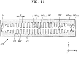
- FIG. 11 is an internal plan view of a Bragg grating 420 according to another exemplary embodiment.
- the Bragg grating 420 includes a core member 423, a plurality of first refractive members 421, and a second refractive member 422.
- the core member 423 may extend from the waveguide 211 of the resonator 210 (see FIG. 6 ) in a lengthwise direction (i.e., x-direction in FIG. 11 ).
- the core member 423 may be integrally formed with the waveguide 211 of the resonator 210.
- the core member 423 may include the same material as that of the waveguide 211 of the resonator 210.
- the core member 423 may include silicon nitride, but is not limited thereto. Otherwise, the core member 423 may include a material different from that of the waveguide 211 of the resonator 210.
- the first refractive members 421 may protrude from the core member 423.
- the first refractive members 421 may protrude from opposite sides of the core member 423 in a width direction of the core member 423 (i.e., y-direction in FIG. 11 ).
- the first refractive members 421 may be spaced apart from each other along the lengthwise direction of the core member 423.
- the first refractive members 421 may be arranged facing each other based on the core member 423, but are not limited thereto.
- the first refractive members 421 may be integrally formed with the core member 423.
- the first refractive members 421 may include the same material as that of the core member 423.
- the first refractive members 421 may include silicon nitride, but is not limited thereto.
- the second refractive member 422 may be provided to fill spaces between the first refractive members 421.
- the second refractive member 422 may include a material having a different refractive index from that of the first refractive members 421.
- the second refractive member 422 may include silicon oxide, but is not limited thereto.
- the second refractive member 422 may be provided to cover the waveguide 211 of the resonator 210 and the first refractive members 421.
- the width W1 of the Bragg grating 420 may be greater than the width D of the waveguide 211 of the resonator 210.
- the width W2 of the core member 423 may be less than the width D of the waveguide 211 of the resonator 210.
- the width W1 of the Bragg grating 420 may correspond to a sum of the protruding lengths L of the two first refractive members 421 that protrude in opposite directions to each other and the width W2 of the core members 423, as described above.
- At least one of the width W2 of the core member 423 and the protruding lengths L of the first refractive member 421 may vary along the lengthwise direction of the core member 423.
- the width W2 of the core member 423 may be gradually reduced from opposite ends thereof toward a center portion thereof.
- the width W1 of the Bragg grating 420 may be gradually increased from the opposite ends of the core member 423 toward the center portion of the core member 423.
- the width W2 of the core member 423 has a maximum value W2 max at the ends of the core member 423 and has a minimum value W2 min at the center of the core member 423 in the lengthwise direction (i.e., x-direction).
- the width W1 of the core member 423 has a maximum value W1 max at the center of the core member 423 and has a minimum value W1 min at the center of the core member 423 in the lengthwise direction. Accordingly, the protruding lengths L of the first refractive members 421 gradually increase from the opposite ends of the core member 423 toward the center portion of the core member 423.
- the intervals between the first refractive members 421, that is, the pitches P between the first refractive members 421, may vary along the lengthwise direction of the core member 423. That is, at least some of the pitches P between the first refractive members 421 may vary along the lengthwise direction of the core member 423.
- FIG. 11 exemplarily shows that the pitches P between the first refractive members 421 are gradually reduced toward the center portion of the core member 423.
- the exemplary embodiment is not limited to the above example, that is, the pitches P between the first refractive members 421 may vary in various manners along the lengthwise direction of the core member 423.
- FIG. 12 is a graph of the reflectivity of the Bragg grating 320 shown in FIG. 9 versus a reflectivity of the Bragg grating 420 of FIG. 11 with respect to a wavelength band of 800 nm to 900 nm.
- the curve C2 denotes the reflectivity of the Bragg grating 320 of FIG. 9
- a curve C3 denotes the reflectivity of the Bragg grating 420 of FIG. 11 .
- the reflectivity is expressed in units of decibels dB.
- the first refractive members 321 and 421 and the second refractive members 322 and 422 in the Bragg gratings 320 and 420 respectively include silicon nitride and silicon oxide.
- the width D of the waveguide 211, the width W1 of the Bragg grating W1, and the width W2 of the core member 323 are respectively 510 nm, 1000 nm, and 200 nm.
- the minimum pitch between the first refractive members 321 is 250 nm, and the pitch varies by 2 nm.
- the width D of the waveguide 211 is 510 nm
- a maximum width W1 max and a minimum width W1 min of the Bragg grating 420 are respectively 1100 nm, and 670 nm.
- a maximum width W2 max and a minimum width W2 min of the core member 423 are respectively 430 nm and 130 nm.
- the minimum pitch between the first refractive members 421 is 250 nm, and the pitch varies by 2 nm.
- the Bragg grating 420 of FIG. 11 in which the width W1 of the Bragg grating 420 varies, exhibits higher reflectivity than the Bragg grating 320 of FIG. 9 having the constant width. Therefore, high reflectivity may be implemented by increasing the width W1 of the Bragg grating 420 toward the center portion of the Bragg grating 420 and reducing the width W2 of the core member 423 toward the center portion of the Bragg grating 420.
- FIG. 13 is a graph of the reflectivity of the Bragg grating 120 of FIG. 3 and the Bragg grating 420 of FIG. 11 with respect to the wavelength band of 800 nm to 900 nm.
- a curve C denotes the reflectivity of the Bragg grating 120 of FIG. 3
- the curve C3 denotes the reflectivity of the Bragg grating 420 of FIG. 11 .
- the reflectivity is expressed in the unit of decibel (dB).
- the Bragg grating 420 of FIG. 11 exhibits higher reflectivity with respect to a wider wavelength band than in the Bragg grating 12 of FIG. 4 .
- the width of the core member 423 is gradually reduced toward the center portion of the Bragg grating 420, and the protruding lengths L of the first refractive members 421 gradually increase toward the center portion of the Bragg grating 420 so that the width W1 of the Bragg grating 420 gradually increases toward the center portion of the Bragg grating 420.
- the width W1 of the Bragg grating 420 may vary by changing the protruding lengths L of the first refractive members 421 while maintaining the width W2 of the core member 423 constantly, or by changing the width W2 of the core member 423 while maintaining the protruding lengths L of the first refractive members 421 constantly.
- the pitches P between the first refractive members 421 may beconstant in further non-claimed examples.
- the high reflectivity may be obtained with respect to a wavelength band of a desired width.
- the higher reflectivity with respect to the wider wavelength band may be obtained by varying the pitches between the first refractive members or varying the width of the Bragg grating.
- the materials included in the first refractive members and the second refractive member may be variously selected in order to obtain higher reflectivity with respect to the visible ray band or other infrared-ray band, and the pitches between the first refractive members or the width of the Bragg grating may be set variously. Accordingly, the spectroscopy device that is manufactured by integrating the spectroscopy units including the above Bragg gratings on a substrate may have improved performance. In addition, the spectroscopy device may be manufactured as a small-sized chip that may be loaded in, for example, a non-invasive blood glucose sensor, and may be implemented as a wearable device.
Landscapes
- Physics & Mathematics (AREA)
- General Physics & Mathematics (AREA)
- Optics & Photonics (AREA)
- Spectroscopy & Molecular Physics (AREA)
- Engineering & Computer Science (AREA)
- Microelectronics & Electronic Packaging (AREA)
- Optical Integrated Circuits (AREA)
- Diffracting Gratings Or Hologram Optical Elements (AREA)
Claims (5)
- Ein Spektrometer (200), das umfasst:einen Resonator (210) mit einem Wellenleiter (211); undein Bragg-Gitter (420), das an einem von zwei unterschiedlichen Enden des Resonators angeordnet ist; undwobei das Bragg-Gitter umfasst:ein Kernelement (423), das sich von dem Wellenleiter des Resonators in einer Längsrichtung des Wellenleiters erstreckt und eine Breite (W2) aufweist, die kleiner als eine Breite (D) des Wellenleiters des Resonators ist;mehrere erste refraktive Elemente (421), die auf entgegengesetzten Seiten des Kernelements in einer Breitenrichtung des Kernelements von dem Kernelement hervorragen und entlang der Längenrichtung voneinander beabstandet sind, wobei Abstände (P) zwischen den ersten refraktiven Elementen entlang der Längsrichtung variieren; undein zweites refraktives Element (422), das Räume zwischen den ersten refraktiven Elementen ausfüllt und einen Brechungsindex aufweist, der von einem Brechungsindex der ersten refraktiven Elemente verschieden ist; und wobeidie Breite (W2) des Kernelements sich zu einem zentralen Bereich des Kernelements hin entlang der Längsrichtung graduell verringert; und die Hervorragungslängen (L) der ersten refraktiven Elemente sich zu dem zentralen Bereich des Kernelements hin entlang der Längsrichtung graduell erhöhen.
- Das Spektrometer von Anspruch 1, wobei das Kernelement und die ersten refraktiven Elemente Siliziumnitrid umfassen.
- Das Spektrometer von Anspruch 1 oder 2, wobei das zweite refraktive Element Siliziumoxid umfasst.
- Das Spektrometer von einem der vorhergehenden Ansprüche, wobei das zweite refraktive Element den Wellenleiter des Resonators, das Kernelement und die mehreren ersten refraktiven Elemente bedeckt.
- Das Spektrometer von Anspruch 1, wobei das Spektrometer (200) ein weiteres Bragg-Gitter (420) umfasst, das an dem anderen der zwei verschiedenen Enden des Resonators angeordnet ist, und wobei das genannte weitere Bragg-Gitter umfasst:ein Kernelement (423), das sich von dem Wellenleiter des Resonators in einer Längsrichtung des Wellenleiters erstreckt und eine Breite (W2) aufweist, die kleiner als eine Breite (D) des Wellenleiters des Resonators ist;mehrere erste refraktive Elemente (421), die auf entgegengesetzten Seiten des Kernelements in einer Breitenrichtung des Kernelements von dem Kernelement hervorragen und entlang der Längenrichtung voneinander beabstandet sind; undein zweites refraktives Element (422), das Räume zwischen den ersten refraktiven Elementen ausfüllt und einen Brechungsindex aufweist, der von einem Brechungsindex der ersten refraktiven Elemente verschieden ist; und wobeidie Breite (W2) des Kernelements sich zu einem zentralen Bereich des Kernelements hin entlang der Längsrichtung graduell verringert; und die Hervorragungslängen (L) der ersten refraktiven Elemente sich zu dem zentralen Bereich des Kernelements hin entlang der Längsrichtung graduell erhöhen.
Applications Claiming Priority (1)
| Application Number | Priority Date | Filing Date | Title |
|---|---|---|---|
| KR1020150166416A KR102568788B1 (ko) | 2015-11-26 | 2015-11-26 | 브래그 격자 및 이를 포함하는 분광 소자 |
Publications (3)
| Publication Number | Publication Date |
|---|---|
| EP3173754A2 EP3173754A2 (de) | 2017-05-31 |
| EP3173754A3 EP3173754A3 (de) | 2017-06-07 |
| EP3173754B1 true EP3173754B1 (de) | 2021-10-06 |
Family
ID=56925955
Family Applications (1)
| Application Number | Title | Priority Date | Filing Date |
|---|---|---|---|
| EP16182955.1A Active EP3173754B1 (de) | 2015-11-26 | 2016-08-05 | Spektroskopievorrichtung mit bragg-gitter |
Country Status (3)
| Country | Link |
|---|---|
| US (2) | US10012539B2 (de) |
| EP (1) | EP3173754B1 (de) |
| KR (1) | KR102568788B1 (de) |
Families Citing this family (3)
| Publication number | Priority date | Publication date | Assignee | Title |
|---|---|---|---|---|
| KR102697425B1 (ko) * | 2017-02-02 | 2024-08-21 | 삼성전자주식회사 | 분광기 및 그 분광기가 적용된 성분 측정 장치 |
| JP2021071575A (ja) * | 2019-10-30 | 2021-05-06 | 沖電気工業株式会社 | 光波長フィルタ |
| ES2833122B2 (es) * | 2019-12-11 | 2022-02-02 | Univ Malaga | Filtro óptico integrado basado en resonadores acoplados mediante redes Bragg fuertes de gran confinamiento lateral |
Family Cites Families (15)
| Publication number | Priority date | Publication date | Assignee | Title |
|---|---|---|---|---|
| US6174648B1 (en) | 1997-07-08 | 2001-01-16 | Oki Electric Industry Co., Ltd. | Optical filter fabrication method using fiber holder with spiral groove and phase mask with spiral diffraction grating |
| FR2813398B1 (fr) | 2000-08-30 | 2003-12-05 | France Telecom | Procede d'apodisation d'un reseau de bragg |
| US7113673B2 (en) * | 2002-01-17 | 2006-09-26 | Cornell Research Foundation, Inc. | High-index contrast distributed Bragg reflector |
| FR2838834A1 (fr) | 2002-04-17 | 2003-10-24 | Highwave Optical Tech | Procede de realisation d'un filtre optique accordable, filtre obtenu et son utilisation |
| WO2003102646A2 (en) | 2002-05-30 | 2003-12-11 | Massachusetts Institute Of Technology | Optical waveguide with non-uniform sidewall gratings |
| GB0416319D0 (en) * | 2004-07-21 | 2004-08-25 | Afton Chemical Ltd | Oil additive |
| JP4774761B2 (ja) | 2005-03-03 | 2011-09-14 | 日本電気株式会社 | 波長可変共振器、波長可変レーザ、光モジュール及びそれらの制御方法 |
| KR100759812B1 (ko) | 2005-12-07 | 2007-09-20 | 한국전자통신연구원 | 테이퍼 도파로 브래그 격자소자 |
| KR100783363B1 (ko) | 2006-09-29 | 2007-12-07 | 한국전자통신연구원 | 가변 도파로 브래그 격자 소자 |
| JP4603090B2 (ja) | 2008-02-29 | 2010-12-22 | 株式会社フジクラ | 基板型光導波路素子、波長分散補償素子およびその設計方法、光フィルタおよびその設計方法、ならびに光共振器およびその設計方法 |
| WO2010030251A2 (en) * | 2008-09-15 | 2010-03-18 | Agency For Science, Technology And Research | Integrated optical sensors operating in the frequency domain |
| US8385696B2 (en) * | 2010-11-12 | 2013-02-26 | The University Of Electro-Communications | Optical nanofiber resonator |
| KR101209627B1 (ko) | 2011-04-29 | 2012-12-07 | 국방과학연구소 | 분광기를 기반으로 하는 광섬유센서 시스템 |
| WO2015099764A1 (en) | 2013-12-27 | 2015-07-02 | Intel Corporation | Asymmetric optical waveguide grating resonators & dbr lasers |
| KR102454950B1 (ko) | 2015-12-11 | 2022-10-14 | 삼성전자주식회사 | 분광기 및 분광기를 포함하는 이미지 센서 |
-
2015
- 2015-11-26 KR KR1020150166416A patent/KR102568788B1/ko active Active
-
2016
- 2016-07-13 US US15/208,953 patent/US10012539B2/en active Active
- 2016-08-05 EP EP16182955.1A patent/EP3173754B1/de active Active
-
2018
- 2018-05-25 US US15/989,386 patent/US10281328B2/en active Active
Also Published As
| Publication number | Publication date |
|---|---|
| US10012539B2 (en) | 2018-07-03 |
| US20180274980A1 (en) | 2018-09-27 |
| KR102568788B1 (ko) | 2023-08-21 |
| US20170153143A1 (en) | 2017-06-01 |
| EP3173754A2 (de) | 2017-05-31 |
| US10281328B2 (en) | 2019-05-07 |
| KR20170061416A (ko) | 2017-06-05 |
| EP3173754A3 (de) | 2017-06-07 |
Similar Documents
| Publication | Publication Date | Title |
|---|---|---|
| JP5304158B2 (ja) | 光共振器及び波長可変レーザ | |
| US9176282B2 (en) | High efficiency mono-order concave diffraction grating | |
| CN101952754B (zh) | 基板型光波导元件、波长色散补偿元件、滤光器和光谐振器以及其设计方法 | |
| CN105319629B (zh) | 通道损耗均匀且通带响应平坦的蚀刻衍射光栅器件 | |
| KR20110031379A (ko) | 하이브리드 도파-모드 공진 필터 및 분포 브래그 반사를 채용하는 방법 | |
| JP3952944B2 (ja) | リング共振回路 | |
| US10281328B2 (en) | Bragg grating, and spectroscopy device including the Bragg grating | |
| US12092872B2 (en) | Wavelength division multiplexer and demultiplexer | |
| US11860411B2 (en) | Super-compact arrayed waveguide grating (AWG) wavelength division multiplexer based on sub-wavelength grating | |
| JP3436891B2 (ja) | 導波路型グレーティングフィルタ | |
| US20210011311A1 (en) | Circular resonator, and optical modulator and optical element comprising same | |
| US9927676B2 (en) | Optical device with integrated reflector(s) comprising a loop reflector integrating a mach-zehnder interferometer | |
| JP6574818B2 (ja) | 波長フィルタ | |
| US7289699B1 (en) | Grating apodization technique for diffused optical waveguides | |
| US10151874B2 (en) | Wavelength division multiplexer | |
| WO2004004082A1 (en) | Optical resonator and laser applications | |
| WO2020162451A1 (ja) | 光機能素子およびレーザ素子 | |
| US10254477B2 (en) | Polarization independent multiplexer / demultiplexer | |
| JP2013041146A (ja) | 波長選択性多モード干渉導波路デバイス | |
| CN113866879B (zh) | 基于布拉格光栅的反射器及其制造方法、光电装置 | |
| CN205120999U (zh) | 一种通道损耗均匀且通带响应平坦的蚀刻衍射光栅器件 | |
| US20140056552A1 (en) | Optical path routing element | |
| JP6714894B2 (ja) | アレイ型光導波路、および半導体光集積素子 | |
| JP2001051138A (ja) | 温度無依存性光合分波器 | |
| JP5817147B2 (ja) | 光フィルタ |
Legal Events
| Date | Code | Title | Description |
|---|---|---|---|
| PUAI | Public reference made under article 153(3) epc to a published international application that has entered the european phase |
Free format text: ORIGINAL CODE: 0009012 |
|
| STAA | Information on the status of an ep patent application or granted ep patent |
Free format text: STATUS: THE APPLICATION HAS BEEN PUBLISHED |
|
| AK | Designated contracting states |
Kind code of ref document: A2 Designated state(s): AL AT BE BG CH CY CZ DE DK EE ES FI FR GB GR HR HU IE IS IT LI LT LU LV MC MK MT NL NO PL PT RO RS SE SI SK SM TR |
|
| AX | Request for extension of the european patent |
Extension state: BA ME |
|
| AK | Designated contracting states |
Kind code of ref document: A3 Designated state(s): AL AT BE BG CH CY CZ DE DK EE ES FI FR GB GR HR HU IE IS IT LI LT LU LV MC MK MT NL NO PL PT RO RS SE SI SK SM TR |
|
| AX | Request for extension of the european patent |
Extension state: BA ME |
|
| RIC1 | Information provided on ipc code assigned before grant |
Ipc: G02B 6/124 20060101ALI20170502BHEP Ipc: G02B 6/293 20060101ALI20170502BHEP Ipc: G01J 3/18 20060101AFI20170502BHEP Ipc: G02B 6/02 20060101ALI20170502BHEP |
|
| PUAL | Search report despatched |
Free format text: ORIGINAL CODE: 0009013 |
|
| STAA | Information on the status of an ep patent application or granted ep patent |
Free format text: STATUS: REQUEST FOR EXAMINATION WAS MADE |
|
| 17P | Request for examination filed |
Effective date: 20171024 |
|
| RBV | Designated contracting states (corrected) |
Designated state(s): AL AT BE BG CH CY CZ DE DK EE ES FI FR GB GR HR HU IE IS IT LI LT LU LV MC MK MT NL NO PL PT RO RS SE SI SK SM TR |
|
| GRAP | Despatch of communication of intention to grant a patent |
Free format text: ORIGINAL CODE: EPIDOSNIGR1 |
|
| STAA | Information on the status of an ep patent application or granted ep patent |
Free format text: STATUS: GRANT OF PATENT IS INTENDED |
|
| INTG | Intention to grant announced |
Effective date: 20210420 |
|
| GRAS | Grant fee paid |
Free format text: ORIGINAL CODE: EPIDOSNIGR3 |
|
| GRAA | (expected) grant |
Free format text: ORIGINAL CODE: 0009210 |
|
| STAA | Information on the status of an ep patent application or granted ep patent |
Free format text: STATUS: THE PATENT HAS BEEN GRANTED |
|
| AK | Designated contracting states |
Kind code of ref document: B1 Designated state(s): AL AT BE BG CH CY CZ DE DK EE ES FI FR GB GR HR HU IE IS IT LI LT LU LV MC MK MT NL NO PL PT RO RS SE SI SK SM TR |
|
| REG | Reference to a national code |
Ref country code: GB Ref legal event code: FG4D |
|
| REG | Reference to a national code |
Ref country code: CH Ref legal event code: EP Ref country code: AT Ref legal event code: REF Ref document number: 1436596 Country of ref document: AT Kind code of ref document: T Effective date: 20211015 |
|
| REG | Reference to a national code |
Ref country code: IE Ref legal event code: FG4D |
|
| REG | Reference to a national code |
Ref country code: DE Ref legal event code: R096 Ref document number: 602016064545 Country of ref document: DE |
|
| REG | Reference to a national code |
Ref country code: LT Ref legal event code: MG9D |
|
| REG | Reference to a national code |
Ref country code: NL Ref legal event code: MP Effective date: 20211006 |
|
| REG | Reference to a national code |
Ref country code: AT Ref legal event code: MK05 Ref document number: 1436596 Country of ref document: AT Kind code of ref document: T Effective date: 20211006 |
|
| PG25 | Lapsed in a contracting state [announced via postgrant information from national office to epo] |
Ref country code: RS Free format text: LAPSE BECAUSE OF FAILURE TO SUBMIT A TRANSLATION OF THE DESCRIPTION OR TO PAY THE FEE WITHIN THE PRESCRIBED TIME-LIMIT Effective date: 20211006 Ref country code: LT Free format text: LAPSE BECAUSE OF FAILURE TO SUBMIT A TRANSLATION OF THE DESCRIPTION OR TO PAY THE FEE WITHIN THE PRESCRIBED TIME-LIMIT Effective date: 20211006 Ref country code: FI Free format text: LAPSE BECAUSE OF FAILURE TO SUBMIT A TRANSLATION OF THE DESCRIPTION OR TO PAY THE FEE WITHIN THE PRESCRIBED TIME-LIMIT Effective date: 20211006 Ref country code: BG Free format text: LAPSE BECAUSE OF FAILURE TO SUBMIT A TRANSLATION OF THE DESCRIPTION OR TO PAY THE FEE WITHIN THE PRESCRIBED TIME-LIMIT Effective date: 20220106 Ref country code: AT Free format text: LAPSE BECAUSE OF FAILURE TO SUBMIT A TRANSLATION OF THE DESCRIPTION OR TO PAY THE FEE WITHIN THE PRESCRIBED TIME-LIMIT Effective date: 20211006 |
|
| PG25 | Lapsed in a contracting state [announced via postgrant information from national office to epo] |
Ref country code: IS Free format text: LAPSE BECAUSE OF FAILURE TO SUBMIT A TRANSLATION OF THE DESCRIPTION OR TO PAY THE FEE WITHIN THE PRESCRIBED TIME-LIMIT Effective date: 20220206 Ref country code: SE Free format text: LAPSE BECAUSE OF FAILURE TO SUBMIT A TRANSLATION OF THE DESCRIPTION OR TO PAY THE FEE WITHIN THE PRESCRIBED TIME-LIMIT Effective date: 20211006 Ref country code: PT Free format text: LAPSE BECAUSE OF FAILURE TO SUBMIT A TRANSLATION OF THE DESCRIPTION OR TO PAY THE FEE WITHIN THE PRESCRIBED TIME-LIMIT Effective date: 20220207 Ref country code: PL Free format text: LAPSE BECAUSE OF FAILURE TO SUBMIT A TRANSLATION OF THE DESCRIPTION OR TO PAY THE FEE WITHIN THE PRESCRIBED TIME-LIMIT Effective date: 20211006 Ref country code: NO Free format text: LAPSE BECAUSE OF FAILURE TO SUBMIT A TRANSLATION OF THE DESCRIPTION OR TO PAY THE FEE WITHIN THE PRESCRIBED TIME-LIMIT Effective date: 20220106 Ref country code: NL Free format text: LAPSE BECAUSE OF FAILURE TO SUBMIT A TRANSLATION OF THE DESCRIPTION OR TO PAY THE FEE WITHIN THE PRESCRIBED TIME-LIMIT Effective date: 20211006 Ref country code: LV Free format text: LAPSE BECAUSE OF FAILURE TO SUBMIT A TRANSLATION OF THE DESCRIPTION OR TO PAY THE FEE WITHIN THE PRESCRIBED TIME-LIMIT Effective date: 20211006 Ref country code: HR Free format text: LAPSE BECAUSE OF FAILURE TO SUBMIT A TRANSLATION OF THE DESCRIPTION OR TO PAY THE FEE WITHIN THE PRESCRIBED TIME-LIMIT Effective date: 20211006 Ref country code: GR Free format text: LAPSE BECAUSE OF FAILURE TO SUBMIT A TRANSLATION OF THE DESCRIPTION OR TO PAY THE FEE WITHIN THE PRESCRIBED TIME-LIMIT Effective date: 20220107 Ref country code: ES Free format text: LAPSE BECAUSE OF FAILURE TO SUBMIT A TRANSLATION OF THE DESCRIPTION OR TO PAY THE FEE WITHIN THE PRESCRIBED TIME-LIMIT Effective date: 20211006 |
|
| REG | Reference to a national code |
Ref country code: DE Ref legal event code: R097 Ref document number: 602016064545 Country of ref document: DE |
|
| PG25 | Lapsed in a contracting state [announced via postgrant information from national office to epo] |
Ref country code: SM Free format text: LAPSE BECAUSE OF FAILURE TO SUBMIT A TRANSLATION OF THE DESCRIPTION OR TO PAY THE FEE WITHIN THE PRESCRIBED TIME-LIMIT Effective date: 20211006 Ref country code: SK Free format text: LAPSE BECAUSE OF FAILURE TO SUBMIT A TRANSLATION OF THE DESCRIPTION OR TO PAY THE FEE WITHIN THE PRESCRIBED TIME-LIMIT Effective date: 20211006 Ref country code: RO Free format text: LAPSE BECAUSE OF FAILURE TO SUBMIT A TRANSLATION OF THE DESCRIPTION OR TO PAY THE FEE WITHIN THE PRESCRIBED TIME-LIMIT Effective date: 20211006 Ref country code: EE Free format text: LAPSE BECAUSE OF FAILURE TO SUBMIT A TRANSLATION OF THE DESCRIPTION OR TO PAY THE FEE WITHIN THE PRESCRIBED TIME-LIMIT Effective date: 20211006 Ref country code: DK Free format text: LAPSE BECAUSE OF FAILURE TO SUBMIT A TRANSLATION OF THE DESCRIPTION OR TO PAY THE FEE WITHIN THE PRESCRIBED TIME-LIMIT Effective date: 20211006 Ref country code: CZ Free format text: LAPSE BECAUSE OF FAILURE TO SUBMIT A TRANSLATION OF THE DESCRIPTION OR TO PAY THE FEE WITHIN THE PRESCRIBED TIME-LIMIT Effective date: 20211006 |
|
| PLBE | No opposition filed within time limit |
Free format text: ORIGINAL CODE: 0009261 |
|
| STAA | Information on the status of an ep patent application or granted ep patent |
Free format text: STATUS: NO OPPOSITION FILED WITHIN TIME LIMIT |
|
| 26N | No opposition filed |
Effective date: 20220707 |
|
| PG25 | Lapsed in a contracting state [announced via postgrant information from national office to epo] |
Ref country code: AL Free format text: LAPSE BECAUSE OF FAILURE TO SUBMIT A TRANSLATION OF THE DESCRIPTION OR TO PAY THE FEE WITHIN THE PRESCRIBED TIME-LIMIT Effective date: 20211006 |
|
| PG25 | Lapsed in a contracting state [announced via postgrant information from national office to epo] |
Ref country code: SI Free format text: LAPSE BECAUSE OF FAILURE TO SUBMIT A TRANSLATION OF THE DESCRIPTION OR TO PAY THE FEE WITHIN THE PRESCRIBED TIME-LIMIT Effective date: 20211006 |
|
| PG25 | Lapsed in a contracting state [announced via postgrant information from national office to epo] |
Ref country code: MC Free format text: LAPSE BECAUSE OF FAILURE TO SUBMIT A TRANSLATION OF THE DESCRIPTION OR TO PAY THE FEE WITHIN THE PRESCRIBED TIME-LIMIT Effective date: 20211006 |
|
| REG | Reference to a national code |
Ref country code: CH Ref legal event code: PL |
|
| PG25 | Lapsed in a contracting state [announced via postgrant information from national office to epo] |
Ref country code: LU Free format text: LAPSE BECAUSE OF NON-PAYMENT OF DUE FEES Effective date: 20220805 Ref country code: LI Free format text: LAPSE BECAUSE OF NON-PAYMENT OF DUE FEES Effective date: 20220831 Ref country code: CH Free format text: LAPSE BECAUSE OF NON-PAYMENT OF DUE FEES Effective date: 20220831 |
|
| REG | Reference to a national code |
Ref country code: BE Ref legal event code: MM Effective date: 20220831 |
|
| PG25 | Lapsed in a contracting state [announced via postgrant information from national office to epo] |
Ref country code: IT Free format text: LAPSE BECAUSE OF FAILURE TO SUBMIT A TRANSLATION OF THE DESCRIPTION OR TO PAY THE FEE WITHIN THE PRESCRIBED TIME-LIMIT Effective date: 20211006 |
|
| PG25 | Lapsed in a contracting state [announced via postgrant information from national office to epo] |
Ref country code: IE Free format text: LAPSE BECAUSE OF NON-PAYMENT OF DUE FEES Effective date: 20220805 |
|
| PG25 | Lapsed in a contracting state [announced via postgrant information from national office to epo] |
Ref country code: BE Free format text: LAPSE BECAUSE OF NON-PAYMENT OF DUE FEES Effective date: 20220831 |
|
| PG25 | Lapsed in a contracting state [announced via postgrant information from national office to epo] |
Ref country code: HU Free format text: LAPSE BECAUSE OF FAILURE TO SUBMIT A TRANSLATION OF THE DESCRIPTION OR TO PAY THE FEE WITHIN THE PRESCRIBED TIME-LIMIT; INVALID AB INITIO Effective date: 20160805 |
|
| PG25 | Lapsed in a contracting state [announced via postgrant information from national office to epo] |
Ref country code: CY Free format text: LAPSE BECAUSE OF FAILURE TO SUBMIT A TRANSLATION OF THE DESCRIPTION OR TO PAY THE FEE WITHIN THE PRESCRIBED TIME-LIMIT Effective date: 20211006 |
|
| PG25 | Lapsed in a contracting state [announced via postgrant information from national office to epo] |
Ref country code: MK Free format text: LAPSE BECAUSE OF FAILURE TO SUBMIT A TRANSLATION OF THE DESCRIPTION OR TO PAY THE FEE WITHIN THE PRESCRIBED TIME-LIMIT Effective date: 20211006 |
|
| PG25 | Lapsed in a contracting state [announced via postgrant information from national office to epo] |
Ref country code: MT Free format text: LAPSE BECAUSE OF FAILURE TO SUBMIT A TRANSLATION OF THE DESCRIPTION OR TO PAY THE FEE WITHIN THE PRESCRIBED TIME-LIMIT Effective date: 20211006 |
|
| PGFP | Annual fee paid to national office [announced via postgrant information from national office to epo] |
Ref country code: DE Payment date: 20250708 Year of fee payment: 10 |
|
| PGFP | Annual fee paid to national office [announced via postgrant information from national office to epo] |
Ref country code: GB Payment date: 20250710 Year of fee payment: 10 |
|
| PGFP | Annual fee paid to national office [announced via postgrant information from national office to epo] |
Ref country code: FR Payment date: 20250708 Year of fee payment: 10 |
|
| PG25 | Lapsed in a contracting state [announced via postgrant information from national office to epo] |
Ref country code: TR Free format text: LAPSE BECAUSE OF FAILURE TO SUBMIT A TRANSLATION OF THE DESCRIPTION OR TO PAY THE FEE WITHIN THE PRESCRIBED TIME-LIMIT Effective date: 20211006 |