EP3173300A1 - Plaque de fermeture et dispositif de motorisation d'entrainement d'essuie-glace de véhicule automobile - Google Patents
Plaque de fermeture et dispositif de motorisation d'entrainement d'essuie-glace de véhicule automobile Download PDFInfo
- Publication number
- EP3173300A1 EP3173300A1 EP16195327.8A EP16195327A EP3173300A1 EP 3173300 A1 EP3173300 A1 EP 3173300A1 EP 16195327 A EP16195327 A EP 16195327A EP 3173300 A1 EP3173300 A1 EP 3173300A1
- Authority
- EP
- European Patent Office
- Prior art keywords
- base
- shaft
- closing
- closing plate
- closure
- Prior art date
- Legal status (The legal status is an assumption and is not a legal conclusion. Google has not performed a legal analysis and makes no representation as to the accuracy of the status listed.)
- Granted
Links
Images
Classifications
-
- B—PERFORMING OPERATIONS; TRANSPORTING
- B60—VEHICLES IN GENERAL
- B60S—SERVICING, CLEANING, REPAIRING, SUPPORTING, LIFTING, OR MANOEUVRING OF VEHICLES, NOT OTHERWISE PROVIDED FOR
- B60S1/00—Cleaning of vehicles
- B60S1/02—Cleaning windscreens, windows or optical devices
- B60S1/04—Wipers or the like, e.g. scrapers
- B60S1/06—Wipers or the like, e.g. scrapers characterised by the drive
- B60S1/08—Wipers or the like, e.g. scrapers characterised by the drive electrically driven
-
- B—PERFORMING OPERATIONS; TRANSPORTING
- B60—VEHICLES IN GENERAL
- B60S—SERVICING, CLEANING, REPAIRING, SUPPORTING, LIFTING, OR MANOEUVRING OF VEHICLES, NOT OTHERWISE PROVIDED FOR
- B60S1/00—Cleaning of vehicles
- B60S1/02—Cleaning windscreens, windows or optical devices
- B60S1/04—Wipers or the like, e.g. scrapers
- B60S1/06—Wipers or the like, e.g. scrapers characterised by the drive
- B60S1/16—Means for transmitting drive
- B60S1/166—Means for transmitting drive characterised by the combination of a motor-reduction unit and a mechanism for converting rotary into oscillatory movement
-
- F—MECHANICAL ENGINEERING; LIGHTING; HEATING; WEAPONS; BLASTING
- F16—ENGINEERING ELEMENTS AND UNITS; GENERAL MEASURES FOR PRODUCING AND MAINTAINING EFFECTIVE FUNCTIONING OF MACHINES OR INSTALLATIONS; THERMAL INSULATION IN GENERAL
- F16C—SHAFTS; FLEXIBLE SHAFTS; ELEMENTS OR CRANKSHAFT MECHANISMS; ROTARY BODIES OTHER THAN GEARING ELEMENTS; BEARINGS
- F16C19/00—Bearings with rolling contact, for exclusively rotary movement
- F16C19/02—Bearings with rolling contact, for exclusively rotary movement with bearing balls essentially of the same size in one or more circular rows
- F16C19/04—Bearings with rolling contact, for exclusively rotary movement with bearing balls essentially of the same size in one or more circular rows for radial load mainly
- F16C19/06—Bearings with rolling contact, for exclusively rotary movement with bearing balls essentially of the same size in one or more circular rows for radial load mainly with a single row or balls
-
- F—MECHANICAL ENGINEERING; LIGHTING; HEATING; WEAPONS; BLASTING
- F16—ENGINEERING ELEMENTS AND UNITS; GENERAL MEASURES FOR PRODUCING AND MAINTAINING EFFECTIVE FUNCTIONING OF MACHINES OR INSTALLATIONS; THERMAL INSULATION IN GENERAL
- F16H—GEARING
- F16H57/00—General details of gearing
- F16H57/02—Gearboxes; Mounting gearing therein
- F16H57/029—Gearboxes; Mounting gearing therein characterised by means for sealing the gearboxes, e.g. to improve airtightness
-
- F—MECHANICAL ENGINEERING; LIGHTING; HEATING; WEAPONS; BLASTING
- F16—ENGINEERING ELEMENTS AND UNITS; GENERAL MEASURES FOR PRODUCING AND MAINTAINING EFFECTIVE FUNCTIONING OF MACHINES OR INSTALLATIONS; THERMAL INSULATION IN GENERAL
- F16H—GEARING
- F16H57/00—General details of gearing
- F16H57/02—Gearboxes; Mounting gearing therein
- F16H57/031—Gearboxes; Mounting gearing therein characterised by covers or lids for gearboxes
-
- F—MECHANICAL ENGINEERING; LIGHTING; HEATING; WEAPONS; BLASTING
- F16—ENGINEERING ELEMENTS AND UNITS; GENERAL MEASURES FOR PRODUCING AND MAINTAINING EFFECTIVE FUNCTIONING OF MACHINES OR INSTALLATIONS; THERMAL INSULATION IN GENERAL
- F16H—GEARING
- F16H57/00—General details of gearing
- F16H57/02—Gearboxes; Mounting gearing therein
- F16H57/039—Gearboxes for accommodating worm gears
-
- F—MECHANICAL ENGINEERING; LIGHTING; HEATING; WEAPONS; BLASTING
- F16—ENGINEERING ELEMENTS AND UNITS; GENERAL MEASURES FOR PRODUCING AND MAINTAINING EFFECTIVE FUNCTIONING OF MACHINES OR INSTALLATIONS; THERMAL INSULATION IN GENERAL
- F16H—GEARING
- F16H57/00—General details of gearing
- F16H57/12—Arrangements for adjusting or for taking-up backlash not provided for elsewhere
-
- H—ELECTRICITY
- H02—GENERATION; CONVERSION OR DISTRIBUTION OF ELECTRIC POWER
- H02K—DYNAMO-ELECTRIC MACHINES
- H02K5/00—Casings; Enclosures; Supports
- H02K5/04—Casings or enclosures characterised by the shape, form or construction thereof
- H02K5/10—Casings or enclosures characterised by the shape, form or construction thereof with arrangements for protection from ingress, e.g. water or fingers
-
- H—ELECTRICITY
- H02—GENERATION; CONVERSION OR DISTRIBUTION OF ELECTRIC POWER
- H02K—DYNAMO-ELECTRIC MACHINES
- H02K5/00—Casings; Enclosures; Supports
- H02K5/04—Casings or enclosures characterised by the shape, form or construction thereof
- H02K5/16—Means for supporting bearings, e.g. insulating supports or means for fitting bearings in the bearing-shields
- H02K5/173—Means for supporting bearings, e.g. insulating supports or means for fitting bearings in the bearing-shields using bearings with rolling contact, e.g. ball bearings
-
- H—ELECTRICITY
- H02—GENERATION; CONVERSION OR DISTRIBUTION OF ELECTRIC POWER
- H02K—DYNAMO-ELECTRIC MACHINES
- H02K5/00—Casings; Enclosures; Supports
- H02K5/04—Casings or enclosures characterised by the shape, form or construction thereof
- H02K5/16—Means for supporting bearings, e.g. insulating supports or means for fitting bearings in the bearing-shields
- H02K5/173—Means for supporting bearings, e.g. insulating supports or means for fitting bearings in the bearing-shields using bearings with rolling contact, e.g. ball bearings
- H02K5/1732—Means for supporting bearings, e.g. insulating supports or means for fitting bearings in the bearing-shields using bearings with rolling contact, e.g. ball bearings radially supporting the rotary shaft at both ends of the rotor
-
- H—ELECTRICITY
- H02—GENERATION; CONVERSION OR DISTRIBUTION OF ELECTRIC POWER
- H02K—DYNAMO-ELECTRIC MACHINES
- H02K7/00—Arrangements for handling mechanical energy structurally associated with dynamo-electric machines, e.g. structural association with mechanical driving motors or auxiliary dynamo-electric machines
- H02K7/08—Structural association with bearings
-
- H—ELECTRICITY
- H02—GENERATION; CONVERSION OR DISTRIBUTION OF ELECTRIC POWER
- H02K—DYNAMO-ELECTRIC MACHINES
- H02K7/00—Arrangements for handling mechanical energy structurally associated with dynamo-electric machines, e.g. structural association with mechanical driving motors or auxiliary dynamo-electric machines
- H02K7/08—Structural association with bearings
- H02K7/081—Structural association with bearings specially adapted for worm gear drives
-
- H—ELECTRICITY
- H02—GENERATION; CONVERSION OR DISTRIBUTION OF ELECTRIC POWER
- H02K—DYNAMO-ELECTRIC MACHINES
- H02K7/00—Arrangements for handling mechanical energy structurally associated with dynamo-electric machines, e.g. structural association with mechanical driving motors or auxiliary dynamo-electric machines
- H02K7/10—Structural association with clutches, brakes, gears, pulleys or mechanical starters
- H02K7/116—Structural association with clutches, brakes, gears, pulleys or mechanical starters with gears
- H02K7/1163—Structural association with clutches, brakes, gears, pulleys or mechanical starters with gears where at least two gears have non-parallel axes without having orbital motion
- H02K7/1166—Structural association with clutches, brakes, gears, pulleys or mechanical starters with gears where at least two gears have non-parallel axes without having orbital motion comprising worm and worm-wheel
-
- F—MECHANICAL ENGINEERING; LIGHTING; HEATING; WEAPONS; BLASTING
- F16—ENGINEERING ELEMENTS AND UNITS; GENERAL MEASURES FOR PRODUCING AND MAINTAINING EFFECTIVE FUNCTIONING OF MACHINES OR INSTALLATIONS; THERMAL INSULATION IN GENERAL
- F16C—SHAFTS; FLEXIBLE SHAFTS; ELEMENTS OR CRANKSHAFT MECHANISMS; ROTARY BODIES OTHER THAN GEARING ELEMENTS; BEARINGS
- F16C2326/00—Articles relating to transporting
- F16C2326/01—Parts of vehicles in general
- F16C2326/09—Windscreen wipers, e.g. pivots therefore
Definitions
- the invention relates to a closure plate for motor vehicle windscreen wiper drive device.
- the invention also relates to a drive device for motor vehicle wiper drive comprising a closure plate.
- the wiper drive motor drives a shaft which carries a worm gear meshing with a gear wheel driving a crankshaft member.
- These drive elements are received in a housing comprising a base closed by a closure plate, the plate having a shaft intended to pass through the vehicle body for the passage of the output shaft driving the wiper blade arm. ice cream.
- the shaft carrying the worm is supported by two bearings, a first bearing receiving one end of the shaft and a second bearing arranged upstream of the engine.
- the first bearing has a ring inserted into a ring housing in the base.
- the ring housing is through.
- An orifice accessible from the outside of the housing allows the introduction of a shaping tool of the ring during assembly of the driving elements of the motorization module.
- the outer orifice is closed by a set screw which abuts against the end of the shaft supported by the ring.
- the pressure screw is used to maintain the shaft and to adjust at least in a summary way the game of the tree. This pressure screw also prevents any entry of water into the housing.
- An object of the present invention is therefore to provide a closure plate and a motorization device at least partially solving the disadvantages of the prior art, which are simple to implement and lower cost.
- the subject of the present invention is a closure plate for motor vehicle windscreen wiper drive device, said device being of the type comprising a base in which is received a shaft carrying a suitable worm screw. to be rotated by a motor and of the type in which said base comprises a ring housing for receiving a ring adapted to support an end of the shaft, said plate comprising a base adapted to close said base, the closure plate being characterized in that it comprises a closing tab integral with the base, serving as a water deflector for an orifice in the end of the ring housing, in the axis of rotation of the shaft.
- the closing tab thus prevents the orifice of the ring housing from constituting an entrance door for droplets of water coming in particular from flows along the barrel of the closing plate.
- Protection of the orifice by the closure plate is simple to implement because performed simultaneously with the closure of the base by positioning the closure plate. This avoids the creation and reference of additional parts, such as a threaded closure screw and a machining of the base, such as tapping, which simplifies the assembly process and limits costs.
- the subject of the invention is also a device for motor vehicle windscreen wiper drive comprising a base in which a shaft carrying a worm screw capable of being rotated by a motor of said device is received.
- base comprising a ring housing in which is received a ring supporting one end of the shaft carrying the worm, an orifice being formed in the end of the ring housing in the axis of rotation of the shaft, characterized in that the drive device comprises a closure plate as described above closing the base and serving as a water deflector for the orifice of the ring housing.
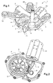
- the motorization device 1 comprises a housing formed of a base 2 ( figure 6 ) and a closure plate 3 ( figure 4 ) closing the base 2.
- the closure plate 3 is fixed to the base 2 for example by means of fixing screws 4.
- the housing houses elements of the drive device 1, including a shaft 5, a toothed wheel 8 and a linkage member 9.
- the base 2 receives the shaft 5 (or armature shaft) carrying a worm 6.
- the shaft 5 protrudes from the rotor of an electric motor 7 protected by a hood 23.
- the base 2 also receives the wheel toothed 8 which meshes the worm 6, as well as the linkage member 9 of the motorization device 1.
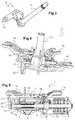
- the linkage member 9 ( figure 3 ) is a crank-rod system having an input shaft 10 and an output shaft 11, articulated.
- the input axis 10 is mounted in an eccentric cavity 12 of the toothed wheel 8 and the output shaft 11 is mounted in a shank 13 projecting from a base 14 of the closure plate 3 (FIG. figure 4 ).
- the barrel 13 is intended to pass through the body of the vehicle for the passage of the output shaft 11 driving the wiper blade arm. Once mounted in the vehicle, the shaft 13 extends vertically.
- the base 14 of the closure plate 3 which closes the base 2 has a general shape of plate.
- the closure plate 3 also comprises a fastening device, such as fixing lugs 15, for example three, connected to the base 14, for fixing the motorization device 1 to the motor vehicle ( figure 1 ).
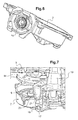
- the drive device 1 comprises a bearing 16 for supporting the shaft 5 carrying the worm screw 6.
- the bearing 16 is for example arranged substantially in the middle of the shaft 5, between the rotor of the motor 7 and the worm 6.
- the bearing 16 can be arranged in a bearing housing 22 of the base 2 intended to be connected to the cover 23 of the motor 7. The bearing 16 is thus arranged at the output of the motor 7.
- a ring housing 17 is further formed in the base 2 to receive one end of the shaft 5 carrying the worm 6.
- the ring housing 17 has a cylindrical shape, coaxial with the axis of rotation of the shaft 5.
- the drive device 1 also comprises a ring, cylindrical, received in the ring housing 17, and supporting the end 5a of the shaft 5.
- an orifice 19 is provided in the axial end of the ring housing 17, the outer side of the base 2, in the axis of rotation of the shaft 5.
- the ring housing 17 is therefore through.
- the orifice 19 allows the introduction of a shaping tool of the ring 18 during the assembly of the elements of the motorization device 1.
- the closure plate 3 further comprises a closing tab 20 integral with the base 14, serving as a water deflector for the orifice 19 ( figures 1 , 4 , 5 , 7 ).
- the closing tab 20 thus prevents the orifice 19 of the ring housing 17 from constituting an entry door for droplets of water coming in particular from flows along the shank 13 of the closure plate 3.
- the protection of the orifice 19 by the closure plate 3 is simple to implement because it is performed simultaneously with the closure of the base 2 by positioning the closure plate 3. This avoids the creation and reference of additional parts. , such as a threaded closure screw and a machining of the base, such as tapping, which simplifies the assembly process and limits costs.
- the closing tab 20 is for example adapted to close the orifice 19, covering it, thereby sealing the access to the ring housing 17 externally. Closing the orifice 19 of the ring housing 17 by the closing tab 20 strengthens the protection of the housing by allowing in particular to prevent the penetration of moisture or dirt and also improves its visual appearance.
- the closing tab 20 extends substantially perpendicular to the base 14.
- the closing tab 20 may have a flat surface so as to come to press the flat surfaces of the base 2 around the orifice 19.
- the end 5a of the shaft 5 is not positioned in abutment against the closure tab 20. There is a gap between the two.
- the closure tongue 20 has for example a rounded end, for example in the form of a "U" full, giving it a robust shape.
- the closure plate 3 comprises at least one reinforcement 21 at least partially carried by the tongue of closure 20 and made of material with the closing tab 20.
- the reinforcement 21 has, for example, a rib shape extending perpendicularly to the flat surface of the closure tongue 20.
- the reinforcement 21 reinforces the mechanical strength of the closure tongue 20, in particular to prevent it from twisting or breaking before the closure plate 3 is mounted on the base 2.
- the reinforcement 21 extends for example on the periphery of the closure tongue 20.
- the reinforcement 21 extends thus along the rounded periphery.
- the reinforcement 21 may further extend over the base 14.
- the reinforcement 21 is extended by two ribs located on each side of the closure tongue 20 on the base 14 ( figure 4 ).
- the closure plate 3 is for example made of plastic material and is obtained in one piece by molding.
Landscapes
- Engineering & Computer Science (AREA)
- General Engineering & Computer Science (AREA)
- Mechanical Engineering (AREA)
- Power Engineering (AREA)
- Connection Of Motors, Electrical Generators, Mechanical Devices, And The Like (AREA)
- Motor Or Generator Frames (AREA)
Abstract
Description
- L'invention concerne une plaque de fermeture pour dispositif de motorisation d'entrainement d'essuie-glace de véhicule automobile. L'invention concerne aussi un dispositif de motorisation d'entrainement d'essuie-glace de véhicule automobile comprenant une plaque de fermeture.
- Le moteur d'entraînement d'essuie-glace entraine un arbre qui porte une vis sans fin engrenant une roue dentée entrainant un organe d'embiellage. Ces éléments d'entrainement sont reçus dans un boitier comprenant un socle fermé par une plaque de fermeture, la plaque présentant un fût destiné à traverser la carrosserie du véhicule pour le passage de l'arbre de sortie entrainant le bras-balai d'essuie-glace.
- Dans le boitier, l'arbre portant la vis sans fin est supporté par deux paliers, un premier palier recevant une extrémité de l'arbre et un deuxième palier agencé en amont du moteur. Le premier palier comporte une bague insérée dans un logement de bague ménagé dans le socle.
- Le logement de bague est traversant. Un orifice accessible depuis l'extérieur du logement permet l'introduction d'un outil de conformation de la bague lors de l'assemblage des éléments d'entrainement du module de motorisation.
- Après conformation de la bague, l'orifice extérieur est fermé par une vis de pression qui vient en butée contre l'extrémité de l'arbre supportée par la bague. La vis de pression permet de maintenir l'arbre et de régler au moins de façon sommaire le jeu de l'arbre. Cette vis de pression empêche également de fait toute entrée d'eau à l'intérieur du boitier.
- Des développements récents ont montré que l'utilisation d'un roulement au niveau du deuxième palier procure un avantage intéressant.
- Cette utilisation rend la vis de pression inutile, l'arbre étant alors suffisamment maintenu serré par le roulement.
- On cherche maintenant à s'affranchir du montage de la vis de pression dans le socle puisqu'elle est devenue inutile, sans toutefois laisser un trou à la place qui pourrait constituer une porte d'entrée pour de l'eau provenant notamment de fuites pouvant s'écouler le long du fût de la plaque de fermeture. L'eau pourrait alors s'infiltrer dans le socle, s'y accumuler et stagner, risquant ainsi de détériorer les éléments d'entrainement.
- Un but de la présente invention est donc de proposer une plaque de fermeture et un dispositif de motorisation résolvant au moins partiellement les inconvénients de l'art antérieur, qui soient simples à mettre en oeuvre et de moindre coût.
- A cet effet, la présente invention a pour objet une plaque de fermeture pour dispositif de motorisation d'entrainement d'essuie-glace de véhicule automobile, ledit dispositif étant du type comprenant un socle dans lequel est reçu un arbre portant une vis sans fin apte à être entrainée en rotation par un moteur et du type dans lequel ledit socle comprend un logement de bague pour recevoir une bague apte à supporter une extrémité de l'arbre, ladite plaque comprenant une embase adaptée pour fermer ledit socle, la plaque de fermeture étant caractérisée en ce qu'elle comporte une languette de fermeture venue de matière avec l'embase, servant de déflecteur d'eau pour un orifice ménagé dans l'extrémité du logement de bague, dans l'axe de rotation de l'arbre.
- La languette de fermeture empêche ainsi à l'orifice du logement de bague de constituer une porte d'entrée pour des gouttelettes d'eau provenant notamment d'écoulements le long du fût de la plaque de fermeture.
- La protection de l'orifice par la plaque de fermeture est simple à mettre en oeuvre car réalisée en même temps que la fermeture du socle par positionnement de la plaque de fermeture. On évite ainsi la création et la référence de pièces supplémentaires, comme une vis filetée de fermeture ainsi qu'un usinage du socle, comme un taraudage, ce qui simplifie le procédé d'assemblage et limite les coûts.
- Selon une ou plusieurs caractéristiques de la plaque de fermeture, prise seule ou en combinaison :
- la languette de fermeture est adaptée pour fermer l'orifice du logement de bague,
- la languette de fermeture s'étend sensiblement perpendiculairement à l'embase,
- la languette de fermeture présente une surface plane,
- la plaque de fermeture comporte au moins un renfort au moins partiellement porté par la languette de fermeture, venu de matière avec la languette de fermeture,
- le renfort s'étend sur la périphérie de la languette de fermeture,
- le renfort s'étend également sur l'embase,
- la languette de fermeture présente une extrémité arrondie,
- la languette de fermeture présente une forme de « U » plein,
- la plaque de fermeture est obtenue par moulage.
- L'invention a aussi pour objet un dispositif de motorisation d'entrainement d'essuie-glace de véhicule automobile, comprenant un socle dans lequel est reçu un arbre portant une vis sans fin apte à être entrainée en rotation par un moteur dudit dispositif, le socle comprenant un logement de bague dans lequel est reçu une bague supportant une extrémité de l'arbre portant la vis sans fin, un orifice étant ménagé dans l'extrémité du logement de bague dans l'axe de rotation de l'arbre, caractérisé en ce que le dispositif de motorisation comporte une plaque de fermeture telle que décrite précédemment fermant le socle et servant de déflecteur d'eau pour l'orifice du logement de bague.
- Selon une ou plusieurs caractéristiques du dispositif de motorisation, prise seule ou en combinaison :
- le dispositif de motorisation comprend un roulement pour supporter l'arbre portant la vis sans fin,
- le roulement est agencé dans un logement de roulement du socle destiné à être raccordé à un boitier du moteur.
- D'autres avantages et caractéristiques apparaîtront à la lecture de la description d'un exemple non limitatif de réalisation de l'invention, ainsi que sur les figures annexées sur lesquelles :
- la
figure 1 montre une vue schématique d'ensemble d'un dispositif de motorisation d'entrainement d'essuie-glace de véhicule automobile, - la
figure 2 montre des éléments du dispositif de motorisation de lafigure 1 , vue de dessus, - la
figure 3 montre une vue en perspective d'un organe d'embiellage du dispositif de motorisation de lafigure 1 , - la
figure 4 montre une vue en perspective d'une plaque de fermeture du dispositif de motorisation de lafigure 1 , - la
figure 5 montre une vue en coupe et de côté du dispositif de motorisation de lafigure 1 , - la
figure 6 montre une vue de côté d'un socle du dispositif de motorisation de lafigure 1 , et - la
figure 7 montre une vue partielle du dispositif de motorisation de lafigure 1 en éclaté, avec la plaque de fermeture positionnée à l'aplomb du socle. - Sur ces figures, les éléments identiques ou analogues portent les mêmes numéros de référence.
- Les réalisations suivantes sont des exemples. Bien que la description se réfère à un ou plusieurs modes de réalisation, ceci ne signifie pas nécessairement que chaque référence concerne le même mode de réalisation, ou que les caractéristiques s'appliquent seulement à un seul mode de réalisation. De simples caractéristiques de différents modes de réalisation peuvent également être combinées pour fournir d'autres réalisations.
- En référence à la
figure 1 , on a représenté un dispositif de motorisation 1 d'entrainement d'essuie-glace de véhicule automobile, notamment pour essuie-glace de vitre arrière. - Le dispositif de motorisation 1 comporte un boitier formé d'un socle 2 (
figure 6 ) et d'une plaque de fermeture 3 (figure 4 ) fermant le socle 2. La plaque de fermeture 3 est fixée au socle 2 par exemple au moyen de vis de fixation 4. Le boitier loge des éléments du dispositif de motorisation 1, notamment un arbre 5, une roue dentée 8 et un organe d'embiellage 9. - Mieux visible sur la
figure 2 , le socle 2 reçoit l'arbre 5 (ou arbre d'induit) portant une vis sans fin 6. L'arbre 5 fait saillie du rotor d'un moteur 7 électrique protégé par un capot 23. Le socle 2 reçoit également la roue dentée 8 qui engrène la vis sans fin 6, ainsi que l'organe d'embiellage 9 du dispositif de motorisation 1. - L'organe d'embiellage 9 (
figure 3 ) est un système bielle-manivelle présentant un axe d'entrée 10 et un axe de sortie 11, articulés. L'axe d'entrée 10 est monté dans une cavité 12 excentrée de la roue dentée 8 et l'axe de sortie 11 est montée dans un fût 13 faisant saillie d'une embase 14 de la plaque de fermeture 3 (figure 4 ). Le fût 13 est destiné à traverser la carrosserie du véhicule pour le passage de l'arbre de sortie 11 entrainant le bras-balai d'essuie-glace. Une fois monté dans le véhicule, le fût 13 s'étend verticalement. - L'embase 14 de la plaque de fermeture 3 qui ferme le socle 2 présente une forme générale de plaque. La plaque de fermeture 3 comporte également un dispositif de fixation, tel que des pattes de fixation 15, par exemple trois, reliées à l'embase 14, pour fixer le dispositif de motorisation 1 au véhicule automobile (
figure 1 ). - Comme on peut le voir sur la vue en coupe de la
figure 5 et sur lafigure 6 , le dispositif de motorisation 1 comprend un roulement 16 pour supporter l'arbre 5 portant la vis sans fin 6. Le roulement 16 est par exemple agencé sensiblement au milieu de l'arbre 5, entre le rotor du moteur 7 et la vis sans fin 6. Le roulement 16 peut être agencé dans un logement de roulement 22 du socle 2 destiné à être raccordé au capot 23 du moteur 7. Le roulement 16 est ainsi agencé en sortie du moteur 7. - Un logement de bague 17 est en outre ménagé dans le socle 2 pour recevoir une extrémité de l'arbre 5 portant la vis sans fin 6. Le logement de bague 17 présente une forme cylindrique, coaxiale à l'axe de rotation de l'arbre 5. Le dispositif de motorisation 1 comporte également une bague 18, cylindrique, reçue dans le logement de bague 17, et supportant l'extrémité 5a de l'arbre 5.
- Comme on peut le voir sur les
figures 5 et7 , un orifice 19 est ménagé dans l'extrémité axiale du logement de bague 17, du côté extérieur du socle 2, dans l'axe de rotation de l'arbre 5. Le logement de bague 17 est donc traversant. L'orifice 19 permet l'introduction d'un outil de conformation de la bague 18 lors de l'assemblage des éléments du dispositif de motorisation 1. - La plaque de fermeture 3 comporte en outre une languette de fermeture 20 venue de matière avec l'embase 14, servant de déflecteur d'eau pour l'orifice 19 (
figures 1 ,4 ,5 ,7 ). La languette de fermeture 20 empêche ainsi à l'orifice 19 du logement de bague 17 de constituer une porte d'entrée pour des gouttelettes d'eau provenant notamment d'écoulements le long du fût 13 de la plaque de fermeture 3. - La protection de l'orifice 19 par la plaque de fermeture 3 est simple à mettre en oeuvre car réalisée en même temps que la fermeture du socle 2 par positionnement de la plaque de fermeture 3. On évite ainsi la création et la référence de pièces supplémentaires, comme une vis filetée de fermeture ainsi qu'un usinage du socle, comme un taraudage, ce qui simplifie le procédé d'assemblage et limite les coûts.
- La languette de fermeture 20 est par exemple adaptée pour fermer l'orifice 19, en le couvrant, obturant ainsi extérieurement l'accès au logement de bague 17. La fermeture de l'orifice 19 du logement de bague 17 par la languette de fermeture 20 renforce la protection du boitier en permettant notamment d'éviter la pénétration d'humidité ou de saletés et améliore aussi son aspect visuel.
- Selon un exemple de réalisation, la languette de fermeture 20 s'étend sensiblement perpendiculairement à l'embase 14. La languette de fermeture 20 peut présenter une surface plane de manière à venir plaquer les surfaces planes du socle 2 autour de l'orifice 19. Comme on peut le voir sur la
figure 5 , l'extrémité 5a de l'arbre 5 n'est pas positionnée en butée contre la languette de fermeture 20. Il subsiste un interstice entre les deux. - La languette de fermeture 20 présente par exemple une extrémité arrondie, par exemple en forme de « U » plein, lui conférant une forme robuste.
- En outre, selon un exemple de réalisation, la plaque de fermeture 3 comporte au moins un renfort 21 au moins partiellement porté par la languette de fermeture 20 et venu de matière avec la languette de fermeture 20.
- Le renfort 21 présente par exemple une forme de nervure s'étendant perpendiculairement à la surface plane de la languette de fermeture 20.
- Le renfort 21 permet de renforcer la tenue mécanique de la languette de fermeture 20, notamment pour éviter qu'elle ne se torde ou se casse avant que la plaque de fermeture 3 ne soit montée sur le socle 2.
- Le renfort 21 s'étend par exemple sur la périphérie de la languette de fermeture 20. Dans le cas d'une languette de fermeture 20 présentant une surface plane et une extrémité arrondie en forme de « U » plein, le renfort 21 s'étend ainsi le long de la périphérie arrondie.
- Le renfort 21 peut en outre s'étendre sur l'embase 14. Ainsi, dans l'exemple, le renfort 21 se prolonge par deux nervures situées de chaque côté de la languette de fermeture 20 sur l'embase 14 (
figure 4 ). - La plaque de fermeture 3 est par exemple en matériau plastique et est obtenue en une seule pièce par moulage.
Claims (13)
- Plaque de fermeture (3) pour dispositif de motorisation (1) d'entrainement d'essuie-glace de véhicule automobile, ledit dispositif (1) étant du type comprenant un socle (2) dans lequel est reçu un arbre (5) portant une vis sans fin (6) apte à être entrainée en rotation par un moteur (7) et du type dans lequel ledit socle (2) comprend un logement de bague (17) pour recevoir une bague (18) apte à supporter une extrémité (5a) de l'arbre (5), ladite plaque (3) comprenant une embase (14) adaptée pour fermer ledit socle (2), la plaque de fermeture (3) étant caractérisée en ce qu'elle comporte une languette de fermeture (20) venue de matière avec l'embase (14), servant de déflecteur d'eau pour un orifice (19) ménagé dans l'extrémité du logement de bague (17), dans l'axe de rotation de l'arbre (5).
- Plaque de fermeture (3) selon la revendication précédente, caractérisée en ce que la languette de fermeture (20) est adaptée pour fermer l'orifice (19) du logement de bague (17).
- Plaque de fermeture (3) selon la revendication précédente, caractérisée en ce que la languette de fermeture (20) s'étend sensiblement perpendiculairement à l'embase (14).
- Plaque de fermeture (3) selon l'une des revendications précédentes, caractérisée en ce que la languette de fermeture (20) présente une surface plane.
- Plaque de fermeture (3) selon l'une des revendications précédentes, caractérisée en ce qu'elle comporte au moins un renfort (21) au moins partiellement porté par la languette de fermeture (20), venu de matière avec la languette de fermeture (20).
- Plaque de fermeture (3) selon la revendication précédente, caractérisée en ce que le renfort (21) s'étend sur la périphérie de la languette de fermeture (20).
- Plaque de fermeture (3) selon l'une des revendications 5 ou 6, caractérisée en ce que le renfort (21) s'étend également sur l'embase (14).
- Plaque de fermeture (3) selon l'une des revendications précédentes, caractérisée en ce que la languette de fermeture (20) présente une extrémité arrondie.
- Plaque de fermeture (3) selon l'une des revendications précédentes, caractérisée en ce que la languette de fermeture (20) présente une forme de « U » plein.
- Plaque de fermeture (3) selon l'une des revendications précédentes, caractérisée en ce qu'elle est obtenue par moulage.
- Dispositif de motorisation (1) d'entrainement d'essuie-glace de véhicule automobile, comprenant un socle (2) dans lequel est reçu un arbre (5) portant une vis sans fin (6) apte à être entrainée en rotation par un moteur (7) dudit dispositif (1), le socle (2) comprenant un logement de bague (17) dans lequel est reçu une bague (18) supportant une extrémité (5a) de l'arbre (5) portant la vis sans fin (6), un orifice (19) étant ménagé dans l'extrémité du logement de bague (17) dans l'axe de rotation de l'arbre (5), caractérisé en ce que le dispositif de motorisation (1) comporte une plaque de fermeture (3) selon l'une des revendications précédentes fermant le socle (2) et servant de déflecteur d'eau pour l'orifice (19) du logement de bague (17).
- Dispositif de motorisation (1) selon la revendication précédente, caractérisé en ce qu'il comprend un roulement (16) pour supporter l'arbre (5) portant la vis sans fin (6).
- Dispositif de motorisation (1) selon la revendication précédente, caractérisé en ce que le roulement (16) est agencé dans un logement de roulement (22) du socle (2) destiné à être raccordé à un boitier (23) du moteur (7).
Applications Claiming Priority (1)
| Application Number | Priority Date | Filing Date | Title |
|---|---|---|---|
| FR1561332A FR3043967B1 (fr) | 2015-11-25 | 2015-11-25 | Plaque de fermeture et dispositif de motorisation d’entrainement d’essuie-glace de vehicule automobile |
Publications (2)
| Publication Number | Publication Date |
|---|---|
| EP3173300A1 true EP3173300A1 (fr) | 2017-05-31 |
| EP3173300B1 EP3173300B1 (fr) | 2019-01-23 |
Family
ID=55073044
Family Applications (1)
| Application Number | Title | Priority Date | Filing Date |
|---|---|---|---|
| EP16195327.8A Active EP3173300B1 (fr) | 2015-11-25 | 2016-10-24 | Plaque de fermeture et dispositif de motorisation d'entrainement d'essuie-glace de véhicule automobile |
Country Status (5)
| Country | Link |
|---|---|
| US (1) | US10227061B2 (fr) |
| EP (1) | EP3173300B1 (fr) |
| JP (1) | JP2017105441A (fr) |
| CN (1) | CN107042812A (fr) |
| FR (1) | FR3043967B1 (fr) |
Citations (4)
| Publication number | Priority date | Publication date | Assignee | Title |
|---|---|---|---|---|
| DE19609973A1 (de) * | 1996-03-14 | 1997-09-18 | Teves Gmbh Alfred | Antriebsvorrichtung für Scheibenwischer mit einem Parkstellungsschalter |
| JPH09327167A (ja) * | 1996-06-06 | 1997-12-16 | Zexel Corp | モータアクチュエータ |
| DE102007058667A1 (de) * | 2007-12-06 | 2009-06-10 | Volkswagen Ag | Scheibenwischeranlage an einem Fahrzeug mit wenigstens einem in eine Servicestellung schwenkbaren Scheibenwischerarm |
| FR2973857A1 (fr) * | 2011-04-06 | 2012-10-12 | Bosch Gmbh Robert | Boitier de transmission de conversion d'essuie-glaces |
Family Cites Families (8)
| Publication number | Priority date | Publication date | Assignee | Title |
|---|---|---|---|---|
| JPH11508987A (ja) * | 1995-06-29 | 1999-08-03 | イーテーテー・アウトモティーフェ・オイローペ・ゲゼルシャフト・ミト・ベシュレンクテル・ハフツング | 伝動装置用ケーシング |
| JP5006713B2 (ja) * | 2007-06-28 | 2012-08-22 | 株式会社ミツバ | ブラシ付き電動モータ |
| WO2009121035A1 (fr) * | 2008-03-28 | 2009-10-01 | Thingap Automotive Llc | Turbo génératrice |
| JP5173668B2 (ja) * | 2008-08-18 | 2013-04-03 | 株式会社ミツバ | 減速機構付モータ |
| CN102044934B (zh) * | 2009-10-21 | 2014-10-22 | 德昌电机(深圳)有限公司 | 电机驱动组件 |
| DE102009055396A1 (de) * | 2009-12-30 | 2011-07-07 | Robert Bosch GmbH, 70469 | Elektrischer Antrieb mit Schneckengetriebe |
| DE102012207129A1 (de) * | 2012-04-27 | 2013-10-31 | Robert Bosch Gmbh | Getriebespindel sowie Spindelgetriebe, sowie Verfahren zum Herstellen einer Getriebespindel |
| US20140250621A1 (en) * | 2013-03-08 | 2014-09-11 | Mitsuba Corporation | Windshield wiper assembly |
-
2015
- 2015-11-25 FR FR1561332A patent/FR3043967B1/fr not_active Expired - Fee Related
-
2016
- 2016-10-24 EP EP16195327.8A patent/EP3173300B1/fr active Active
- 2016-11-18 CN CN201611027251.4A patent/CN107042812A/zh active Pending
- 2016-11-18 US US15/355,171 patent/US10227061B2/en not_active Expired - Fee Related
- 2016-11-24 JP JP2016228232A patent/JP2017105441A/ja active Pending
Patent Citations (4)
| Publication number | Priority date | Publication date | Assignee | Title |
|---|---|---|---|---|
| DE19609973A1 (de) * | 1996-03-14 | 1997-09-18 | Teves Gmbh Alfred | Antriebsvorrichtung für Scheibenwischer mit einem Parkstellungsschalter |
| JPH09327167A (ja) * | 1996-06-06 | 1997-12-16 | Zexel Corp | モータアクチュエータ |
| DE102007058667A1 (de) * | 2007-12-06 | 2009-06-10 | Volkswagen Ag | Scheibenwischeranlage an einem Fahrzeug mit wenigstens einem in eine Servicestellung schwenkbaren Scheibenwischerarm |
| FR2973857A1 (fr) * | 2011-04-06 | 2012-10-12 | Bosch Gmbh Robert | Boitier de transmission de conversion d'essuie-glaces |
Also Published As
| Publication number | Publication date |
|---|---|
| FR3043967B1 (fr) | 2019-04-19 |
| FR3043967A1 (fr) | 2017-05-26 |
| US20170144632A1 (en) | 2017-05-25 |
| US10227061B2 (en) | 2019-03-12 |
| CN107042812A (zh) | 2017-08-15 |
| JP2017105441A (ja) | 2017-06-15 |
| EP3173300B1 (fr) | 2019-01-23 |
Similar Documents
| Publication | Publication Date | Title |
|---|---|---|
| FR2865981A1 (fr) | Moto-reducteur notamment pour mecanisme d'essuie-glace de vehicule automobile | |
| FR2985699A1 (fr) | Dispositif de protection d'une membrane respirante, groupe motoreducteur et systeme d'essuyage muni d'un tel dispositif | |
| BE1000789A6 (fr) | Ensemble d'une vitre de verre et d'un organe de joint d'arete pour vehicules a moteur. | |
| EP3173300B1 (fr) | Plaque de fermeture et dispositif de motorisation d'entrainement d'essuie-glace de véhicule automobile | |
| EP3495183B1 (fr) | Ouvrant de véhicule comprenant un élément de garnissage en saillie | |
| FR2942285A1 (fr) | Groupe de transmission et vehicule comportant un tel groupe de transmission. | |
| EP3992403A1 (fr) | Actionneur electromecanique pour vehicule automobile | |
| EP0852195A1 (fr) | Système d'essuyage comportant un palier en matière plastique | |
| FR2488071A1 (fr) | Moteur electrique de demarrage pour moteurs a combustion interne | |
| FR3105635A1 (fr) | Coupelle de rotor extérieur pour moteur de ventilateur d’une installation de de chauffage, ventilation et/ou climatisation d’un véhicule automobile | |
| FR3055255B1 (fr) | Ouvrant d’un vehicule automobile equipe d’un dispositif leve-vitre perfectionne | |
| FR3031075B1 (fr) | Bras d'essuie-glace de dispositif d'essuie-glace | |
| FR3036674A1 (fr) | Groupe motoreducteur comprenant une membrane respirante | |
| FR2947602A1 (fr) | Dispositif d'entrainement d'un element reglable de vehicule automobile | |
| EP3121073B1 (fr) | Organe de sortie, dispositif de motorisation pour l entrainement d au moins un bras d essuie-glace de vehicule automobile et procede de fabrication d'un organe de sortie | |
| FR2947966A1 (fr) | Unite motrice d'une transmission | |
| EP3802241B1 (fr) | Dispositif essuie-vitre integrant une commande de manoeuvre d'un ouvrant | |
| EP2079610B1 (fr) | Capot de protection pour systeme integrant de l'electronique | |
| EP3077257B1 (fr) | Dispositif de connexion bras-balai, balai d'essuie-glace et ensemble d'essuyage | |
| FR3157843A1 (fr) | Bras d’actionnement et dispositif d’essuyage | |
| FR2720704A1 (fr) | Interrupteur d'arrêt automatique monté dans un moteur d'essuie-glace. | |
| FR3147185A1 (fr) | Dispositif et système d’essuyage de véhicule | |
| EP0656287B1 (fr) | Moto-réducteur, notamment pour un dispositif d'essuie-glace de véhicule automobile | |
| FR3144556A1 (fr) | Élément de carrosserie de véhicule automobile et véhicule automobile comprenant un tel élément | |
| FR2892685A1 (fr) | Module d'essuie lunette arriere multifonctions de vehicule automobile |
Legal Events
| Date | Code | Title | Description |
|---|---|---|---|
| PUAI | Public reference made under article 153(3) epc to a published international application that has entered the european phase |
Free format text: ORIGINAL CODE: 0009012 |
|
| STAA | Information on the status of an ep patent application or granted ep patent |
Free format text: STATUS: REQUEST FOR EXAMINATION WAS MADE |
|
| 17P | Request for examination filed |
Effective date: 20161024 |
|
| AK | Designated contracting states |
Kind code of ref document: A1 Designated state(s): AL AT BE BG CH CY CZ DE DK EE ES FI FR GB GR HR HU IE IS IT LI LT LU LV MC MK MT NL NO PL PT RO RS SE SI SK SM TR |
|
| AX | Request for extension of the european patent |
Extension state: BA ME |
|
| STAA | Information on the status of an ep patent application or granted ep patent |
Free format text: STATUS: EXAMINATION IS IN PROGRESS |
|
| RIC1 | Information provided on ipc code assigned before grant |
Ipc: B60S 1/16 20060101AFI20180206BHEP Ipc: F16H 57/029 20120101ALI20180206BHEP Ipc: F16H 57/031 20120101ALI20180206BHEP Ipc: H02K 7/08 20060101ALI20180206BHEP Ipc: F16H 57/039 20120101ALI20180206BHEP Ipc: H02K 5/173 20060101ALI20180206BHEP Ipc: H02K 7/116 20060101ALN20180206BHEP Ipc: H02K 5/10 20060101ALN20180206BHEP |
|
| 17Q | First examination report despatched |
Effective date: 20180307 |
|
| RIC1 | Information provided on ipc code assigned before grant |
Ipc: H02K 7/08 20060101ALI20180802BHEP Ipc: B60S 1/16 20060101AFI20180802BHEP Ipc: H02K 7/116 20060101ALN20180802BHEP Ipc: F16C 19/06 20060101ALI20180802BHEP Ipc: F16H 57/039 20120101ALI20180802BHEP Ipc: H02K 5/10 20060101ALN20180802BHEP Ipc: H02K 5/173 20060101ALI20180802BHEP Ipc: F16H 57/031 20120101ALI20180802BHEP Ipc: F16H 57/029 20120101ALI20180802BHEP Ipc: F16H 57/12 20060101ALI20180802BHEP |
|
| GRAP | Despatch of communication of intention to grant a patent |
Free format text: ORIGINAL CODE: EPIDOSNIGR1 |
|
| STAA | Information on the status of an ep patent application or granted ep patent |
Free format text: STATUS: GRANT OF PATENT IS INTENDED |
|
| INTG | Intention to grant announced |
Effective date: 20180907 |
|
| GRAS | Grant fee paid |
Free format text: ORIGINAL CODE: EPIDOSNIGR3 |
|
| GRAA | (expected) grant |
Free format text: ORIGINAL CODE: 0009210 |
|
| STAA | Information on the status of an ep patent application or granted ep patent |
Free format text: STATUS: THE PATENT HAS BEEN GRANTED |
|
| AK | Designated contracting states |
Kind code of ref document: B1 Designated state(s): AL AT BE BG CH CY CZ DE DK EE ES FI FR GB GR HR HU IE IS IT LI LT LU LV MC MK MT NL NO PL PT RO RS SE SI SK SM TR |
|
| REG | Reference to a national code |
Ref country code: GB Ref legal event code: FG4D Free format text: NOT ENGLISH |
|
| REG | Reference to a national code |
Ref country code: CH Ref legal event code: EP |
|
| REG | Reference to a national code |
Ref country code: AT Ref legal event code: REF Ref document number: 1091203 Country of ref document: AT Kind code of ref document: T Effective date: 20190215 |
|
| REG | Reference to a national code |
Ref country code: IE Ref legal event code: FG4D Free format text: LANGUAGE OF EP DOCUMENT: FRENCH |
|
| REG | Reference to a national code |
Ref country code: DE Ref legal event code: R096 Ref document number: 602016009417 Country of ref document: DE |
|
| REG | Reference to a national code |
Ref country code: NL Ref legal event code: MP Effective date: 20190123 |
|
| PG25 | Lapsed in a contracting state [announced via postgrant information from national office to epo] |
Ref country code: NL Free format text: LAPSE BECAUSE OF FAILURE TO SUBMIT A TRANSLATION OF THE DESCRIPTION OR TO PAY THE FEE WITHIN THE PRESCRIBED TIME-LIMIT Effective date: 20190123 |
|
| PG25 | Lapsed in a contracting state [announced via postgrant information from national office to epo] |
Ref country code: FI Free format text: LAPSE BECAUSE OF FAILURE TO SUBMIT A TRANSLATION OF THE DESCRIPTION OR TO PAY THE FEE WITHIN THE PRESCRIBED TIME-LIMIT Effective date: 20190123 Ref country code: LT Free format text: LAPSE BECAUSE OF FAILURE TO SUBMIT A TRANSLATION OF THE DESCRIPTION OR TO PAY THE FEE WITHIN THE PRESCRIBED TIME-LIMIT Effective date: 20190123 Ref country code: PL Free format text: LAPSE BECAUSE OF FAILURE TO SUBMIT A TRANSLATION OF THE DESCRIPTION OR TO PAY THE FEE WITHIN THE PRESCRIBED TIME-LIMIT Effective date: 20190123 Ref country code: NO Free format text: LAPSE BECAUSE OF FAILURE TO SUBMIT A TRANSLATION OF THE DESCRIPTION OR TO PAY THE FEE WITHIN THE PRESCRIBED TIME-LIMIT Effective date: 20190423 Ref country code: PT Free format text: LAPSE BECAUSE OF FAILURE TO SUBMIT A TRANSLATION OF THE DESCRIPTION OR TO PAY THE FEE WITHIN THE PRESCRIBED TIME-LIMIT Effective date: 20190523 Ref country code: SE Free format text: LAPSE BECAUSE OF FAILURE TO SUBMIT A TRANSLATION OF THE DESCRIPTION OR TO PAY THE FEE WITHIN THE PRESCRIBED TIME-LIMIT Effective date: 20190123 Ref country code: ES Free format text: LAPSE BECAUSE OF FAILURE TO SUBMIT A TRANSLATION OF THE DESCRIPTION OR TO PAY THE FEE WITHIN THE PRESCRIBED TIME-LIMIT Effective date: 20190123 |
|
| REG | Reference to a national code |
Ref country code: AT Ref legal event code: MK05 Ref document number: 1091203 Country of ref document: AT Kind code of ref document: T Effective date: 20190123 |
|
| PG25 | Lapsed in a contracting state [announced via postgrant information from national office to epo] |
Ref country code: GR Free format text: LAPSE BECAUSE OF FAILURE TO SUBMIT A TRANSLATION OF THE DESCRIPTION OR TO PAY THE FEE WITHIN THE PRESCRIBED TIME-LIMIT Effective date: 20190424 Ref country code: BG Free format text: LAPSE BECAUSE OF FAILURE TO SUBMIT A TRANSLATION OF THE DESCRIPTION OR TO PAY THE FEE WITHIN THE PRESCRIBED TIME-LIMIT Effective date: 20190423 Ref country code: HR Free format text: LAPSE BECAUSE OF FAILURE TO SUBMIT A TRANSLATION OF THE DESCRIPTION OR TO PAY THE FEE WITHIN THE PRESCRIBED TIME-LIMIT Effective date: 20190123 Ref country code: IS Free format text: LAPSE BECAUSE OF FAILURE TO SUBMIT A TRANSLATION OF THE DESCRIPTION OR TO PAY THE FEE WITHIN THE PRESCRIBED TIME-LIMIT Effective date: 20190523 Ref country code: RS Free format text: LAPSE BECAUSE OF FAILURE TO SUBMIT A TRANSLATION OF THE DESCRIPTION OR TO PAY THE FEE WITHIN THE PRESCRIBED TIME-LIMIT Effective date: 20190123 Ref country code: LV Free format text: LAPSE BECAUSE OF FAILURE TO SUBMIT A TRANSLATION OF THE DESCRIPTION OR TO PAY THE FEE WITHIN THE PRESCRIBED TIME-LIMIT Effective date: 20190123 |
|
| REG | Reference to a national code |
Ref country code: DE Ref legal event code: R097 Ref document number: 602016009417 Country of ref document: DE |
|
| PG25 | Lapsed in a contracting state [announced via postgrant information from national office to epo] |
Ref country code: AL Free format text: LAPSE BECAUSE OF FAILURE TO SUBMIT A TRANSLATION OF THE DESCRIPTION OR TO PAY THE FEE WITHIN THE PRESCRIBED TIME-LIMIT Effective date: 20190123 Ref country code: EE Free format text: LAPSE BECAUSE OF FAILURE TO SUBMIT A TRANSLATION OF THE DESCRIPTION OR TO PAY THE FEE WITHIN THE PRESCRIBED TIME-LIMIT Effective date: 20190123 Ref country code: DK Free format text: LAPSE BECAUSE OF FAILURE TO SUBMIT A TRANSLATION OF THE DESCRIPTION OR TO PAY THE FEE WITHIN THE PRESCRIBED TIME-LIMIT Effective date: 20190123 Ref country code: IT Free format text: LAPSE BECAUSE OF FAILURE TO SUBMIT A TRANSLATION OF THE DESCRIPTION OR TO PAY THE FEE WITHIN THE PRESCRIBED TIME-LIMIT Effective date: 20190123 Ref country code: SK Free format text: LAPSE BECAUSE OF FAILURE TO SUBMIT A TRANSLATION OF THE DESCRIPTION OR TO PAY THE FEE WITHIN THE PRESCRIBED TIME-LIMIT Effective date: 20190123 Ref country code: CZ Free format text: LAPSE BECAUSE OF FAILURE TO SUBMIT A TRANSLATION OF THE DESCRIPTION OR TO PAY THE FEE WITHIN THE PRESCRIBED TIME-LIMIT Effective date: 20190123 Ref country code: RO Free format text: LAPSE BECAUSE OF FAILURE TO SUBMIT A TRANSLATION OF THE DESCRIPTION OR TO PAY THE FEE WITHIN THE PRESCRIBED TIME-LIMIT Effective date: 20190123 |
|
| PG25 | Lapsed in a contracting state [announced via postgrant information from national office to epo] |
Ref country code: SM Free format text: LAPSE BECAUSE OF FAILURE TO SUBMIT A TRANSLATION OF THE DESCRIPTION OR TO PAY THE FEE WITHIN THE PRESCRIBED TIME-LIMIT Effective date: 20190123 |
|
| PLBE | No opposition filed within time limit |
Free format text: ORIGINAL CODE: 0009261 |
|
| STAA | Information on the status of an ep patent application or granted ep patent |
Free format text: STATUS: NO OPPOSITION FILED WITHIN TIME LIMIT |
|
| PG25 | Lapsed in a contracting state [announced via postgrant information from national office to epo] |
Ref country code: AT Free format text: LAPSE BECAUSE OF FAILURE TO SUBMIT A TRANSLATION OF THE DESCRIPTION OR TO PAY THE FEE WITHIN THE PRESCRIBED TIME-LIMIT Effective date: 20190123 |
|
| 26N | No opposition filed |
Effective date: 20191024 |
|
| PG25 | Lapsed in a contracting state [announced via postgrant information from national office to epo] |
Ref country code: SI Free format text: LAPSE BECAUSE OF FAILURE TO SUBMIT A TRANSLATION OF THE DESCRIPTION OR TO PAY THE FEE WITHIN THE PRESCRIBED TIME-LIMIT Effective date: 20190123 |
|
| PG25 | Lapsed in a contracting state [announced via postgrant information from national office to epo] |
Ref country code: TR Free format text: LAPSE BECAUSE OF FAILURE TO SUBMIT A TRANSLATION OF THE DESCRIPTION OR TO PAY THE FEE WITHIN THE PRESCRIBED TIME-LIMIT Effective date: 20190123 |
|
| PG25 | Lapsed in a contracting state [announced via postgrant information from national office to epo] |
Ref country code: MC Free format text: LAPSE BECAUSE OF FAILURE TO SUBMIT A TRANSLATION OF THE DESCRIPTION OR TO PAY THE FEE WITHIN THE PRESCRIBED TIME-LIMIT Effective date: 20190123 |
|
| REG | Reference to a national code |
Ref country code: CH Ref legal event code: PL |
|
| PG25 | Lapsed in a contracting state [announced via postgrant information from national office to epo] |
Ref country code: CH Free format text: LAPSE BECAUSE OF NON-PAYMENT OF DUE FEES Effective date: 20191031 Ref country code: LI Free format text: LAPSE BECAUSE OF NON-PAYMENT OF DUE FEES Effective date: 20191031 Ref country code: LU Free format text: LAPSE BECAUSE OF NON-PAYMENT OF DUE FEES Effective date: 20191024 |
|
| REG | Reference to a national code |
Ref country code: BE Ref legal event code: MM Effective date: 20191031 |
|
| PG25 | Lapsed in a contracting state [announced via postgrant information from national office to epo] |
Ref country code: BE Free format text: LAPSE BECAUSE OF NON-PAYMENT OF DUE FEES Effective date: 20191031 |
|
| PG25 | Lapsed in a contracting state [announced via postgrant information from national office to epo] |
Ref country code: IE Free format text: LAPSE BECAUSE OF NON-PAYMENT OF DUE FEES Effective date: 20191024 |
|
| PG25 | Lapsed in a contracting state [announced via postgrant information from national office to epo] |
Ref country code: CY Free format text: LAPSE BECAUSE OF FAILURE TO SUBMIT A TRANSLATION OF THE DESCRIPTION OR TO PAY THE FEE WITHIN THE PRESCRIBED TIME-LIMIT Effective date: 20190123 |
|
| GBPC | Gb: european patent ceased through non-payment of renewal fee |
Effective date: 20201024 |
|
| PG25 | Lapsed in a contracting state [announced via postgrant information from national office to epo] |
Ref country code: HU Free format text: LAPSE BECAUSE OF FAILURE TO SUBMIT A TRANSLATION OF THE DESCRIPTION OR TO PAY THE FEE WITHIN THE PRESCRIBED TIME-LIMIT; INVALID AB INITIO Effective date: 20161024 Ref country code: MT Free format text: LAPSE BECAUSE OF FAILURE TO SUBMIT A TRANSLATION OF THE DESCRIPTION OR TO PAY THE FEE WITHIN THE PRESCRIBED TIME-LIMIT Effective date: 20190123 |
|
| PG25 | Lapsed in a contracting state [announced via postgrant information from national office to epo] |
Ref country code: GB Free format text: LAPSE BECAUSE OF NON-PAYMENT OF DUE FEES Effective date: 20201024 |
|
| PG25 | Lapsed in a contracting state [announced via postgrant information from national office to epo] |
Ref country code: MK Free format text: LAPSE BECAUSE OF FAILURE TO SUBMIT A TRANSLATION OF THE DESCRIPTION OR TO PAY THE FEE WITHIN THE PRESCRIBED TIME-LIMIT Effective date: 20190123 |
|
| P01 | Opt-out of the competence of the unified patent court (upc) registered |
Effective date: 20230528 |
|
| PGFP | Annual fee paid to national office [announced via postgrant information from national office to epo] |
Ref country code: DE Payment date: 20251015 Year of fee payment: 10 |
|
| PGFP | Annual fee paid to national office [announced via postgrant information from national office to epo] |
Ref country code: FR Payment date: 20251027 Year of fee payment: 10 |