EP3173293B1 - Strukturelement - Google Patents
Strukturelement Download PDFInfo
- Publication number
- EP3173293B1 EP3173293B1 EP16194656.1A EP16194656A EP3173293B1 EP 3173293 B1 EP3173293 B1 EP 3173293B1 EP 16194656 A EP16194656 A EP 16194656A EP 3173293 B1 EP3173293 B1 EP 3173293B1
- Authority
- EP
- European Patent Office
- Prior art keywords
- structural member
- indent
- vehicle
- indents
- structural
- Prior art date
- Legal status (The legal status is an assumption and is not a legal conclusion. Google has not performed a legal analysis and makes no representation as to the accuracy of the status listed.)
- Not-in-force
Links
- 238000000034 method Methods 0.000 claims description 15
- 238000004519 manufacturing process Methods 0.000 claims description 4
- 239000000463 material Substances 0.000 claims description 4
- 238000005304 joining Methods 0.000 claims description 3
- 230000005540 biological transmission Effects 0.000 description 2
- 230000006378 damage Effects 0.000 description 2
- 208000027418 Wounds and injury Diseases 0.000 description 1
- 238000010521 absorption reaction Methods 0.000 description 1
- 239000000853 adhesive Substances 0.000 description 1
- 230000001070 adhesive effect Effects 0.000 description 1
- 239000011324 bead Substances 0.000 description 1
- 238000005219 brazing Methods 0.000 description 1
- 238000002485 combustion reaction Methods 0.000 description 1
- 230000000694 effects Effects 0.000 description 1
- 238000005242 forging Methods 0.000 description 1
- 208000014674 injury Diseases 0.000 description 1
- 238000009740 moulding (composite fabrication) Methods 0.000 description 1
- 238000003825 pressing Methods 0.000 description 1
- 238000003466 welding Methods 0.000 description 1
Images


Classifications
-
- B—PERFORMING OPERATIONS; TRANSPORTING
- B60—VEHICLES IN GENERAL
- B60R—VEHICLES, VEHICLE FITTINGS, OR VEHICLE PARTS, NOT OTHERWISE PROVIDED FOR
- B60R19/00—Wheel guards; Radiator guards, e.g. grilles; Obstruction removers; Fittings damping bouncing force in collisions
- B60R19/02—Bumpers, i.e. impact receiving or absorbing members for protecting vehicles or fending off blows from other vehicles or objects
- B60R19/24—Arrangements for mounting bumpers on vehicles
- B60R19/26—Arrangements for mounting bumpers on vehicles comprising yieldable mounting means
- B60R19/34—Arrangements for mounting bumpers on vehicles comprising yieldable mounting means destroyed upon impact, e.g. one-shot type
-
- B—PERFORMING OPERATIONS; TRANSPORTING
- B62—LAND VEHICLES FOR TRAVELLING OTHERWISE THAN ON RAILS
- B62D—MOTOR VEHICLES; TRAILERS
- B62D21/00—Understructures, i.e. chassis frame on which a vehicle body may be mounted
- B62D21/15—Understructures, i.e. chassis frame on which a vehicle body may be mounted having impact absorbing means, e.g. a frame designed to permanently or temporarily change shape or dimension upon impact with another body
- B62D21/152—Front or rear frames
-
- B—PERFORMING OPERATIONS; TRANSPORTING
- B21—MECHANICAL METAL-WORKING WITHOUT ESSENTIALLY REMOVING MATERIAL; PUNCHING METAL
- B21D—WORKING OR PROCESSING OF SHEET METAL OR METAL TUBES, RODS OR PROFILES WITHOUT ESSENTIALLY REMOVING MATERIAL; PUNCHING METAL
- B21D39/00—Application of procedures in order to connect objects or parts, e.g. coating with sheet metal otherwise than by plating; Tube expanders
- B21D39/02—Application of procedures in order to connect objects or parts, e.g. coating with sheet metal otherwise than by plating; Tube expanders of sheet metal by folding, e.g. connecting edges of a sheet to form a cylinder
- B21D39/026—Reinforcing the connection by locally deforming
-
- B—PERFORMING OPERATIONS; TRANSPORTING
- B21—MECHANICAL METAL-WORKING WITHOUT ESSENTIALLY REMOVING MATERIAL; PUNCHING METAL
- B21D—WORKING OR PROCESSING OF SHEET METAL OR METAL TUBES, RODS OR PROFILES WITHOUT ESSENTIALLY REMOVING MATERIAL; PUNCHING METAL
- B21D53/00—Making other particular articles
- B21D53/88—Making other particular articles other parts for vehicles, e.g. cowlings, mudguards
-
- B—PERFORMING OPERATIONS; TRANSPORTING
- B60—VEHICLES IN GENERAL
- B60R—VEHICLES, VEHICLE FITTINGS, OR VEHICLE PARTS, NOT OTHERWISE PROVIDED FOR
- B60R19/00—Wheel guards; Radiator guards, e.g. grilles; Obstruction removers; Fittings damping bouncing force in collisions
-
- B—PERFORMING OPERATIONS; TRANSPORTING
- B60—VEHICLES IN GENERAL
- B60R—VEHICLES, VEHICLE FITTINGS, OR VEHICLE PARTS, NOT OTHERWISE PROVIDED FOR
- B60R19/00—Wheel guards; Radiator guards, e.g. grilles; Obstruction removers; Fittings damping bouncing force in collisions
- B60R19/02—Bumpers, i.e. impact receiving or absorbing members for protecting vehicles or fending off blows from other vehicles or objects
- B60R19/023—Details
-
- B—PERFORMING OPERATIONS; TRANSPORTING
- B60—VEHICLES IN GENERAL
- B60R—VEHICLES, VEHICLE FITTINGS, OR VEHICLE PARTS, NOT OTHERWISE PROVIDED FOR
- B60R19/00—Wheel guards; Radiator guards, e.g. grilles; Obstruction removers; Fittings damping bouncing force in collisions
- B60R19/02—Bumpers, i.e. impact receiving or absorbing members for protecting vehicles or fending off blows from other vehicles or objects
- B60R19/24—Arrangements for mounting bumpers on vehicles
-
- B—PERFORMING OPERATIONS; TRANSPORTING
- B62—LAND VEHICLES FOR TRAVELLING OTHERWISE THAN ON RAILS
- B62D—MOTOR VEHICLES; TRAILERS
- B62D21/00—Understructures, i.e. chassis frame on which a vehicle body may be mounted
- B62D21/15—Understructures, i.e. chassis frame on which a vehicle body may be mounted having impact absorbing means, e.g. a frame designed to permanently or temporarily change shape or dimension upon impact with another body
- B62D21/152—Front or rear frames
- B62D21/155—Sub-frames or underguards
-
- F—MECHANICAL ENGINEERING; LIGHTING; HEATING; WEAPONS; BLASTING
- F16—ENGINEERING ELEMENTS AND UNITS; GENERAL MEASURES FOR PRODUCING AND MAINTAINING EFFECTIVE FUNCTIONING OF MACHINES OR INSTALLATIONS; THERMAL INSULATION IN GENERAL
- F16F—SPRINGS; SHOCK-ABSORBERS; MEANS FOR DAMPING VIBRATION
- F16F7/00—Vibration-dampers; Shock-absorbers
- F16F7/12—Vibration-dampers; Shock-absorbers using plastic deformation of members
- F16F7/128—Vibration-dampers; Shock-absorbers using plastic deformation of members characterised by the members, e.g. a flat strap, yielding through stretching, pulling apart
-
- B—PERFORMING OPERATIONS; TRANSPORTING
- B60—VEHICLES IN GENERAL
- B60Y—INDEXING SCHEME RELATING TO ASPECTS CROSS-CUTTING VEHICLE TECHNOLOGY
- B60Y2306/00—Other features of vehicle sub-units
- B60Y2306/01—Reducing damages in case of crash, e.g. by improving battery protection
-
- F—MECHANICAL ENGINEERING; LIGHTING; HEATING; WEAPONS; BLASTING
- F16—ENGINEERING ELEMENTS AND UNITS; GENERAL MEASURES FOR PRODUCING AND MAINTAINING EFFECTIVE FUNCTIONING OF MACHINES OR INSTALLATIONS; THERMAL INSULATION IN GENERAL
- F16F—SPRINGS; SHOCK-ABSORBERS; MEANS FOR DAMPING VIBRATION
- F16F2230/00—Purpose; Design features
- F16F2230/36—Holes, slots or the like
Definitions
- the present disclosure relates to a structural member and is particularly, although not exclusively, concerned with a structural member configured to provide improved energy absorption of a crash structure.
- Vehicles such as motor vehicles, often include one or more crash structures configured to sacrificially deform in the case of a collision to prevent injury to vehicle occupants and/or damage to other components of a vehicle.
- Crash structures are often configured to dissipate as much energy as possible during their deformation. It is often desirable to minimise the deceleration of the vehicle during a collision, by minimising the peak force experienced during deformation of the crash structure.
- Many vehicles comprise an internal combustion engine, which is often provided towards the front of the vehicle.
- the engine may collide with the obstacle before the crash structure has fully deformed.
- the momentum of the engine may represent a significant proportion of the momentum of the vehicle and hence, an impact between the engine and the obstacle may greatly reduce the momentum of the vehicle. This may allow the crash structure to maintain a low level of deceleration of the vehicle throughout its deformation.
- Document GB1507218 discloses a vehicle frame consisting of two box-sectioned longitudinal members connected by a transverse member at each end characterized in that the end regions of each longitudinal member are weakened by beads pressed into and/or pressed out of at least one corner of the box-section to reduce the longitudinal compressive rigidity of the frame.
- GB1507218 discloses a structural member for a front of a motor vehicle, the structural member being configured to extend in a longitudinal direction of the vehicle, wherein the structural member has a polygonal cross-sectional shape, the longitudinal projection of which defines a plurality of surfaces, wherein at least one of the surfaces has a plurality of indents provided on the surface, the indents being spaced apart from one another in the longitudinal direction, wherein a first indent on the at least one surface is larger in size than a second indent on the at least one surface, the second indent being further from the front of the vehicle than the first indent.
- a structural member for a front of a motor vehicle the structural member being configured to extend in a longitudinal direction of the vehicle, wherein the structural member has a polygonal cross-sectional shape, the longitudinal projection of which defines a plurality of surfaces, wherein at least one of the surfaces has a plurality of indents provided on the surface, the indents being spaced apart from one another in the longitudinal direction, wherein a first indent on the at least one surface is larger in size than a second indent on the at least one surface, the second indent being further from the front of the vehicle than the first indent, wherein a further indent is provided on an inboard side of the structural member and a corresponding indent is not provided on an opposite outboard side of the structural member, wherein the further indent is provided near an end of the structural member that is furthest from the front of the vehicle.
- the indents may successively decrease in size from the front of the vehicle. The indents encourage the successive
- the indents may have a depth relative to the surrounding surface.
- the depth of the first indent may be greater than the depth of the second indent.
- the indents may have a width extending in a direction perpendicular to the longitudinal direction of the vehicle.
- the width of the first indent may be greater than the width of the second indent.
- One or more of the indents on the at least one surface may extend over part of the width of the surface.
- one or more of the indents on the at least one surface may extend over the entire width of the surface.
- a particular surface may comprise indents extending over part of the surface width and indents that extend over entire surface width.
- the indents on a first surface may be longitudinally interspersed with indents from a second, e.g. neighbouring, surface.
- Each surface may have a plurality of indents provided thereon.
- alternate surfaces may have a plurality of indents provided thereon.
- Corresponding indents may be provided on opposite surfaces of the structural member.
- the further indent may extend across one or more of the surfaces.
- the structural member may form a support rail, e.g. forming a sub-frame of the vehicle. Additionally or alternatively, the structural member may form a crash can provided between a support rail and bumper of the vehicle.
- the structural member may have a substantially constant, e.g. constant, cross-sectional size and/or shape.
- the structural member may be tubular, e.g. hollow.
- the structural member may have a square, hexagonal or octagonal cross-sectional shape.
- the surfaces may be formed by walls defining edges of the cross-sectional shape.
- a vehicle may comprise a first pair of structural members as mentioned above.
- the first pair of structural members may be laterally spaced apart from one another.
- the first pair of structural members may be support rails forming a sub-frame of the vehicle or crash cans provided between a support rail and bumper of the vehicle.
- the vehicle may further comprise a second pair of structural members as described above.
- the second pair of structural members may be laterally spaced apart from one another.
- the second pair of structural members may be coupled to respective structural members of the first pair.
- the second pair of structural members may be the other of support rails forming a sub-frame of the vehicle or crash cans provided between a support rail and bumper of the vehicle.
- the structural members may be provided inboard of wheel arches of the vehicle.
- the structural members may be provided at the front of the vehicle.
- a powertrain, e.g. engine, transmission and/or motor, of the vehicle may be provided at a rear of the vehicle.
- a structural member for a front of a motor vehicle the structural member being configured to extend in a longitudinal direction of the vehicle, wherein the method comprises:
- the method may further comprise folding two or more sheets of material to form respective portions of the polygonal cross-sectional shape.
- the method may further comprise joining the two or more sheets together.
- the method may further comprise placing the structural member in a mandrel.
- the method may further comprise stamping or striking the structural member to form the indents.
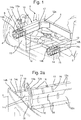
- a vehicle such as a motor vehicle 2 may comprise a front bumper 4 supported by a crash structure 10.
- the crash structure may be coupled to a cross member 6 of the vehicle.
- the vehicle may also comprise a plurality of wheels 8 configured to drive the vehicle.
- the crash structure 10 may comprises one or more structural members, such as one or more crash cans 14 and/or one or more support rails 12. As depicted in Figure 1 , a pair of support rails 12 is provided and each support rail 12 may be coupled at a first end 12a of the support rail to the cross member 6. The support rails 12 may extend away from the cross member 6. The support rails 12 may extend in a longitudinal direction of the vehicle. For example, as shown in Figure 1 , the support rails may extend from the cross member 6 towards the front of the vehicle, e.g. towards the front bumper 4.
- a second end 12b of each of the support rails may be coupled to a first end 14a of a respective crash cans 14.
- the support rails 12 and/or the crash cans 14 may comprise one of more flanges configured to allow the crash cans 14 and the support rails 12 to be coupled using mechanical fasteners, such as bolts or rivets.
- the support rails 12 may be coupled to the crash cans 14 using any other method, such as welding or brazing or using an adhesive.
- a joint plate 15 may be provided at the interface between the second end 12b of each the support rails 12 and the first end 14a of each of the crash cans 14.
- the joint plate 15 may be coupled to the support rail and the crash can at their interface.
- the joint plate 15 may be omitted.
- each of the crash cans 14 may be axially aligned, e.g. on a longitudinal axis, with the support rail 12 to which they are coupled.
- the crash cans 14 may not be aligned with the support rails 14.
- the crash cans may be laterally or vertically offset from the support rails.
- a second end 14b of each of the crash cans 14 may be coupled to the front bumper 4.
- the front bumper 4 may be configured to receive a load from an obstacle (not shown) during a collision of the vehicle with the obstacle, and transfer the load to the crash structure 10.
- the front bumper 4 may be configured to receive substantially all of the load applied to the vehicle during a front on collision.
- the structural members 14, 12 of the crash structure may be provided between the wheels 8 of the vehicle 2, e.g. inboard of each of the wheels.
- the structural members 14, 12 may be provided inboard of wheel arches of the vehicle (not shown), which may be formed in one or more body panels of the vehicle.
- the arrangement of the structural members 14, 12 of the crash structure 10 shown in Figure 1 may be possible when the powertrain of the vehicle, e.g. an engine and/or motor and transmission (not shown), is not provided at the front of the vehicle.
- the powertrain may be provided at a rear of the vehicle and/or at one or more wheels 8 of the vehicle.
- the structural members 14, 12 may have a substantially constant cross-sectional shape.
- the structural members may have a substantially constant octagonal shape in cross-section.
- the structural member may have a square, hexagonal or any other polygonal shape in cross-section.
- the size, e.g. area, of the cross-section may vary from one end of the structural member to the other.
- the structural members 14, 12 may be tapered.
- the cross-sections of the crash cans 14 and the supports rails 12 may be the same shape. Alternatively, the cross-section of the crash cans 14 may be a different shape from the cross-section of the support rails 12.
- one or more surfaces 12c, 14c may be defined by the longitudinal projection of the cross-section of the structural member 14, 12. At least one of the surfaces 12c, 14c, may comprise one or more indents 16, 18. As depicted in Figures 2a and 2b , each of the surfaces 12c, 14c may comprise one or more indents 18. The indents 16, 18 may be spaced apart from each other, e.g. longitudinally, along the support member.
- the indents 16, 18 may extend at least partially across a width of one or more surfaces 12c, 14c of the structural member, e.g. in a direction perpendicular to the longitudinal direction of the vehicle. One or more of the indents may extend over substantially the entire width of the surface 12c, 14c. In other words, the indents 16, 18 may have a width (measured in the direction perpendicular to the longitudinal direction of the vehicle), which is less than or equal to the width of the surface 12c, 14c in which they are formed.
- the indents 16, 18 may have a depth relative to the surrounding surface 12c, 14c.
- the indents may be rounded and/or comprise rounded bottoms, e.g. a cross-section of the indents in a plane parallel to the longitudinal direction of the vehicle may be substantially semi-circular or comprise a sector of a circle or ellipse.
- the cross-section of the indent 16, 18 may be any other shape, such as substantially triangular or substantially square.
- the indents 16, 18 may be provided on each of the surfaces 12c, 14c of the crash can 14 and the support rail 12.
- Each surface may comprise a plurality of indents.
- the indents 16, 18 formed in opposite surfaces of the support members may correspond, for example the indents 16, 18 in opposite surfaces may be the same width and/or depth and/or may be provided at the same longitudinal locations.
- the indents 16, 18 formed in adjacent, e.g. neighbouring, surfaces may be dissimilar.
- Indents 16, 18 on one or more surfaces may have a different width and/or depth and/or may be provided at different longitudinal locations to those provided on one or more adjacent surface.
- indents provided on one or more surfaces 12c, 14c may be longitudinally interspersed with the indents provided on one or more adjacent surfaces.
- the size, e.g. the depth, span and/or width of the indents 16, 18 provided on the surfaces 12c, 14c may vary along the length, e.g. longitudinal length, of the surfaces 12c, 14c (the indent span may be measured in the longitudinal direction of the vehicle).
- the size, e.g. depth, span and/or width, of successive indents may decrease from the front of the crash structure 10 towards the rear of the crash structure 10.
- a first indent 18a provided towards the front of the vehicle 2 e.g. towards a second end 12b of the crash can, may have a greater depth than a second indent 18b provided towards the first end 12a of the crash can, e.g.
- first indent 18a may have a greater width and/or span than the second indent 18b.
- two or more of the indents 16, 18 spaced apart along one of the surfaces 12c, 14c may be grouped into pairs, threes or larger groups, which may be the same size as the others in the group.
- the structural members 12, 14 may be formed from one or more folded sheets 22, 24, which may be joined at or near their ends to provide the structural member.
- the structural member may be formed from two folded sheets, however it is equally envisaged that one or more than two folded sheets may be used to form the structural member.
- the structural member 12, 14 may be formed from a first side sheet 22 and a second side sheet 24.
- the first and second side sheets 22, 24 may be substantially the same size and/or shape.
- one or more end surfaces 22a, 24a at each end of one of the side sheets 22, 24 may be overlapped with one or more end surfaces 22a, 24a provided at each end of the other of the side sheets to form first and second joints 26, 28.
- the side sheets may be joined at the joints 26, 28 using any appropriate method.
- the first and second side sheets may be bolted, riveted, welded and/or brazed together.
- the side sheets 22, 24 may be vertically or laterally offset, such that the at one of the joints the end surfaces 22a of the first side sheet 22 are provided on the outside of the structural member 12, 14 and at the other of the joints, the end surfaces 22a of the first side sheet 22 are provided on an inside of the structural member 12, 14.
- the first and second side sheets may be different sizes and the end surfaces of one of the side sheets may be provided on the outside of the structural member 12, 14 at each of the joints.
- the method 500 comprises a first step 502 in which one or more sheets of material are folded and a second step 504 in which the folded sheet are joined (at their ends), e.g. as described above with reference to Figure 2c , to form a substantially constant polygonal cross-sectional shape, the longitudinal projection of which defines a plurality of surfaces.
- the method 500 further comprises a third step 506, in which a plurality of indents are formed on at least one of the surfaces of the structural member.
- the indents may vary in size, e.g. depth, span and/or width along the length of the structural member.
- the indents may be produced using a pressing, forming or forging process.
- the indents may be formed by striking the structural member with a tool configured to provide the desired, shape, depth, span and/or width of indent.
- the structural members 12, 14 may be configured to collapse in order to dissipate the kinetic energy lost by the vehicles 2 and/or the obstacle during the collision.
- the surfaces 12a, 14a of the structural members may be configured to buckle locally and fold in order to dissipate energy.
- the indents 16, 18 may encourage the structural member to collapse in a successive manner during an impact between the vehicle 2 and the obstacle.
- the indents 18 in the crash can 14 may be configured such that the crash can 14 initially begins to collapse at or towards the second end 14b of the crash can. The collapse of the crash can 14 may propagate towards the first end 14a, e.g. such that the crash can 14 collapses successively from the front of the vehicle 2 rearwards.
- the indents 16, provided in the support rail 12 may be configured such that, once the crash can 14 has substantially completely collapsed, the support rail 12 begins to collapse at or towards the second end 12b of the support rail 12. Similar to the crash can 14, the indents 16 in the support rail 12 may be configured to encourage the successive collapse of the support rail 12 from the second end 12b towards the first end 12a.
- Encouraging successive collapse of the structural members 12, 14, as described above, may lead to more complete collapse of the structural members such that a greater amount of energy may be dissipated by the crash structure 10.
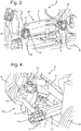
- the support rail 12 may be provided with a further indent 17.
- the further indent 17 may be provided on an inboard side of the support rail 12 at or towards the first end 12a of the support rail.
- the further indent may extend at least partially over the width of the surface 12c.
- the further indent may extend over one or more surfaces 12c of the support rail.
- the further indent 17 may be configured to affect the direction in which the support rail collapses during a side or offset impact with an obstacle (not shown).
- Figure 4 depicts the crash structure 10 following an impact with an offset obstacle.
- the further indent 17 has been configured to encourage the support rail to collapse inwards (relative to the vehicle 2) during the collision.
- the inwards collapsing of the support rail 12 may increase the energy dissipated by the collapsing of the crash structure 10 and/or may reduce the deceleration of the vehicle 2 during the collision.
- a corresponding indent may not be provided on an opposite outboard side of the support rail.
Landscapes
- Engineering & Computer Science (AREA)
- Mechanical Engineering (AREA)
- Chemical & Material Sciences (AREA)
- Combustion & Propulsion (AREA)
- Transportation (AREA)
- General Engineering & Computer Science (AREA)
- Body Structure For Vehicles (AREA)
- Vibration Dampers (AREA)
Claims (13)
- Bauteil (12, 14) für eine Frontseite eines Kraftfahrzeugs (2), wobei das Bauteil ausgestaltet ist, um sich in einer Längsrichtung des Fahrzeugs zu erstrecken, wobei das Bauteil eine polygonale Querschnittsform aufweist, deren längsgerichteter Vorsprung eine Vielzahl von Oberflächen (12c, 14c) definiert, wobei mindestens eine der Oberflächen eine Vielzahl von Einkerbungen (16, 18) aufweist, die auf der Oberfläche vorgesehen sind, wobei die Einkerbungen in der Längsrichtung voneinander beabstandet sind, wobei eine erste Einkerbung (18a) auf der mindestens einen Oberfläche größer ist als eine zweite Einkerbung (18b) auf der mindestens einen Oberfläche, wobei die zweite Einkerbung weiter weg von der Frontseite des Fahrzeugs liegt als die erste Einkerbung, derart, dass die Einkerbungen den folgenden Zusammenbruch des Bauteils während eines Kollisionsvorgangs stärken, und dadurch gekennzeichnet, dass eine weitere Einkerbung (17) an der Innenbordseite des Bauteils vorgesehen ist und eine entsprechende Einkerbung an einer gegenüberliegenden Außenbordseite des Bauteils nicht vorgesehen ist, wobei die weitere Einkerbung in der Nähe eines Endes des Bauteils vorgesehen ist, welches am weitesten weg von der Frontseite des Fahrzeugs liegt.
- Bauteil (12, 14) nach Anspruch 1, wobei die Einkerbungen (16, 18) eine Tiefe bezüglich der umgebenden Oberfläche aufweisen und die Tiefe der ersten Einkerbung (18a) größer ist als die Tiefe der zweiten Einkerbung (18b).
- Bauteil (12, 14) nach Anspruch 1 oder 2, wobei die Einkerbungen (16, 18) eine Breite aufweisen, die sich in einer Richtung senkrecht zur Längsrichtung des Fahrzeugs erstreckt, und die Breite der ersten Einkerbung (18a) größer ist als die Breite der zweiten Einkerbung (18b).
- Bauteil (12, 14) nach einem der vorhergehenden Ansprüche, wobei eine oder mehrere Einkerbungen (16, 18) auf der mindestens einen Oberfläche (12c, 14c) sich über einen Teil der Oberfläche oder die gesamte Breite der Oberfläche erstrecken.
- Bauteil (12, 14) nach einem der vorhergehenden Ansprüche, wobei die Einkerbungen (16, 18) auf einer ersten Oberfläche längslaufend mit Einkerbungen von einer zweiten benachbarten Oberfläche verschachtelt sind.
- Bauteil (12, 14) nach einem der vorhergehenden Ansprüche, wobei jede Oberfläche (12c, 14c) eine Vielzahl von Einkerbungen, die darauf vorgesehen sind, aufweist.
- Bauteil (12, 14) nach einem der vorhergehenden Ansprüche, wobei entsprechende Einkerbungen auf gegenüberliegenden Oberflächen des Bauteils vorgesehen sind.
- Bauteil (12, 14) nach einem der vorhergehenden Ansprüche, wobei das Bauteil eine Tragschiene (12) und/oder ein Stoßblech (14), das zwischen der Tragschiene und der Stoßstange (4) des Fahrzeugs vorgesehen ist, ausbildet.
- Bauteil (12, 14) nach einem der vorhergehenden Ansprüche, wobei das Bauteil eine quadratische, sechseckige oder achteckige Querschnittsform aufweist.
- Fahrzeug (2), welches ein erstes Paar Bauteile (12, 14) nach einem der vorhergehenden Ansprüche umfasst, wobei das erste Paar Bauteile seitlich voneinander beabstandet ist.
- Fahrzeug (2) nach Anspruch 10, wobei das Fahrzeug ferner ein zweites Paar Bauteile (12, 14) nach einem der Ansprüche 1 bis 9 umfasst, wobei das zweite Paar Bauteile seitlich voneinander beabstandet ist und mit den jeweiligen Bauteilen des ersten Paars gekoppelt ist.
- Fahrzeug (2) nach Anspruch 10 oder 11, wobei die Bauteile (12, 14) innenliegend von Radläufen des Fahrzeugs vorgesehen sind.
- Verfahren (500) zum Herstellen eines Bauteils (12, 14) für eine Frontseite eines Kraftfahrzeugs (2), wobei das Bauteil ausgestaltet ist, um sich in einer Längsrichtung des Fahrzeugs zu erstrecken, wobei das Verfahren umfasst:Falzen und Zusammenfügen eines oder mehrerer Bleche (22, 24) von Material, um eine im Wesentlichen konstante polygonale Querschnittsform auszubilden, deren längsgerichteter Vorsprung eine Vielzahl von Oberflächen (12c, 14c) definiert;Ausbilden einer Vielzahl von Einkerbungen (16, 18) auf mindestens einer der Oberflächen, wobei die Einkerbungen in der Längsrichtung voneinander beabstandet sind, wobei eine erste Einkerbung (18a) auf der mindestens einen Oberfläche größer ist als eine zweite Einkerbung (18b) auf der mindestens einen Oberfläche, die zweite Einkerbung weiter weg von der Frontseite des Fahrzeugs liegt als die erste Einkerbung, derart, dass die Einkerbungen den folgenden Zusammenbruch des Bauteils während eines Kollisionsvorgangs stärken, und gekennzeichnet durchAusbilden einer weiteren Einkerbung (17) an der Innenbordseite des Bauteils, wobei eine entsprechende Einkerbung an einer gegenüberliegenden Außenbordseite des Bauteils nicht vorgesehen ist, wobei die weitere Einkerbung in der Nähe eines Endes des Bauteils vorgesehen ist, welches am weitesten weg von der Frontseite des Fahrzeugs liegt.
Applications Claiming Priority (1)
| Application Number | Priority Date | Filing Date | Title |
|---|---|---|---|
| GB1520996.8A GB2544795A (en) | 2015-11-27 | 2015-11-27 | A structural member |
Publications (2)
| Publication Number | Publication Date |
|---|---|
| EP3173293A1 EP3173293A1 (de) | 2017-05-31 |
| EP3173293B1 true EP3173293B1 (de) | 2018-12-12 |
Family
ID=55177367
Family Applications (1)
| Application Number | Title | Priority Date | Filing Date |
|---|---|---|---|
| EP16194656.1A Not-in-force EP3173293B1 (de) | 2015-11-27 | 2016-10-19 | Strukturelement |
Country Status (6)
| Country | Link |
|---|---|
| US (1) | US9834160B2 (de) |
| EP (1) | EP3173293B1 (de) |
| CN (1) | CN106809152A (de) |
| GB (1) | GB2544795A (de) |
| MX (1) | MX2016015496A (de) |
| RU (1) | RU2715982C2 (de) |
Cited By (1)
| Publication number | Priority date | Publication date | Assignee | Title |
|---|---|---|---|---|
| WO2025155706A1 (en) * | 2024-01-17 | 2025-07-24 | Shape Corp. | Front rail with crash tuning features |
Families Citing this family (15)
| Publication number | Priority date | Publication date | Assignee | Title |
|---|---|---|---|---|
| US10144376B2 (en) * | 2016-12-09 | 2018-12-04 | GM Global Technology Operations LLC | Cap design for fiber-reinforced composite crush members |
| US10214243B2 (en) * | 2017-07-11 | 2019-02-26 | Ford Global Technologies, Llc | Vehicle frame |
| CN107963043B (zh) * | 2017-11-23 | 2021-04-06 | 陕西科技大学 | 一种三级组合式车辆碰撞集成系统及方法 |
| US10518811B2 (en) | 2018-01-18 | 2019-12-31 | Honda Motor Co., Ltd. | Front side frame member for a vehicle front frame assembly |
| DE102018129724B4 (de) * | 2018-11-26 | 2022-08-04 | Benteler Automobiltechnik Gmbh | Fahrzeugbauteil für ein Fahrzeug |
| CN109664849B (zh) * | 2019-01-14 | 2020-09-25 | 大连理工大学 | 一种基于剪纸图案设计的碰撞吸能盒 |
| JP7124728B2 (ja) * | 2019-01-25 | 2022-08-24 | トヨタ自動車株式会社 | 車両構造 |
| DE102020201772B4 (de) * | 2019-04-05 | 2025-07-24 | Ford Global Technologies, Llc | Crashbox für ein Kraftfahrzeug |
| KR102663542B1 (ko) * | 2019-05-07 | 2024-05-03 | 현대자동차주식회사 | 차량의 프런트엔드모듈 프레임 |
| JP7260777B2 (ja) * | 2019-05-31 | 2023-04-19 | キョーラク株式会社 | 衝撃吸収体 |
| US10926803B2 (en) * | 2019-07-17 | 2021-02-23 | GM Global Technology Operations LLC | Four rail front crush structure with load dissemination into eight element support structure |
| USD1045716S1 (en) | 2021-10-28 | 2024-10-08 | Soucy International Inc. | Tubular member for a vehicle accessory |
| US12179840B2 (en) * | 2023-04-26 | 2024-12-31 | Ford Global Technologies, Llc | Notches of frame rails of three-wheeled vehicle |
| EP4538123A1 (de) * | 2023-10-09 | 2025-04-16 | Benteler Automobiltechnik GmbH | Crashbox fuer eine stossfaengeranordnung eines kraftfahrzeugs sowie eine stossfaengeranordnung eines kraftfahrzeugs mit zwei solcher crashboxen und ein verfahren zur herstellung einer solchen stossfaengeranordnung |
| WO2025095906A1 (en) * | 2023-11-01 | 2025-05-08 | Sakarya Uygulamali Bi̇li̇mler Üni̇versi̇tesi̇ Rektörlüğü | A crash box for absorbing impact energy released in an accident |
Family Cites Families (23)
| Publication number | Priority date | Publication date | Assignee | Title |
|---|---|---|---|---|
| DE1801960C2 (de) * | 1968-10-09 | 1971-04-29 | Opel Adam Ag | Fahrzeugrahmen |
| DE2459519B1 (de) * | 1974-12-17 | 1976-04-22 | Daimler Benz Ag | Fahrzeugrahmen |
| US4431221A (en) * | 1982-02-26 | 1984-02-14 | The Budd Company | Bumper beam for an automobile |
| US4684151A (en) * | 1986-03-21 | 1987-08-04 | General Motors Corporation | Controlled collapsible frame rail |
| JP2595724B2 (ja) * | 1989-08-30 | 1997-04-02 | 日産自動車株式会社 | 強度部材の製造方法 |
| US5246263A (en) * | 1991-01-18 | 1993-09-21 | Mazda Motor Corporation | Rear body structure of vehicle |
| JP3738508B2 (ja) * | 1996-12-13 | 2006-01-25 | 日産自動車株式会社 | 車体の前部フレーム構造 |
| US5853195A (en) * | 1997-01-16 | 1998-12-29 | Ford Global Technologies, Inc. | Front rail assembly for a vehicle |
| DE19958996A1 (de) * | 1999-12-08 | 2001-06-13 | Daimler Chrysler Ag | Querträgermodul für einen front- oder heckseitigen Stirnbereich eines Kraftfahrzeugs |
| DE10161432A1 (de) * | 2001-12-14 | 2003-07-03 | Hella Behr Fahrzeugsysteme | Haltevorrichtung für ein Kühlmodul |
| US6588830B1 (en) * | 2002-07-01 | 2003-07-08 | Daimlerchrysler Corporation | Energy absorbing frame rail tip |
| DE102004002948B4 (de) * | 2004-01-21 | 2008-01-31 | Daimler Ag | Vorrichtung zur Stoßenergieaufnahme bei Fahrzeugen |
| US7389860B2 (en) * | 2004-03-29 | 2008-06-24 | The Texas A&M University System | Energy absorbing device having notches and pre-bent sections |
| JP2006347265A (ja) * | 2005-06-14 | 2006-12-28 | Toyota Motor Corp | 車両の衝撃吸収部材 |
| DE102005029738B4 (de) * | 2005-06-24 | 2018-10-04 | GM Global Technology Operations LLC (n. d. Ges. d. Staates Delaware) | Energieabsorberelement und dieses verwendende Kraftfahrzeugkarosserie |
| DE102006015876A1 (de) * | 2006-04-05 | 2007-10-11 | GM Global Technology Operations, Inc., Detroit | Crashbox und Dämpfungsanordnung mit Crasbox |
| US7341299B1 (en) * | 2006-09-06 | 2008-03-11 | Ford Global Technologies, Llc | Double cell crushable joint for automotive front end |
| WO2009056652A1 (es) * | 2007-11-02 | 2009-05-07 | Autotech Engineering A.I.E. | Absorbedor de energía para conjunto parachoques de vehículo, y método para la fabricación del mismo |
| JP5168477B2 (ja) * | 2008-03-26 | 2013-03-21 | スズキ株式会社 | 車両のクラッシュボックス及び車体前部構造 |
| CN102015376B (zh) * | 2008-07-23 | 2013-03-27 | 丰臣机工株式会社 | 撞击力吸收部件 |
| DE102011112256A1 (de) * | 2011-09-02 | 2013-03-07 | GM Global Technology Operations LLC (n. d. Gesetzen des Staates Delaware) | Kraftfahrzeug mit Crashbox |
| JP5659185B2 (ja) * | 2012-04-05 | 2015-01-28 | 豊田鉄工株式会社 | 車両用衝撃吸収部材 |
| JP5637203B2 (ja) * | 2012-12-04 | 2014-12-10 | トヨタ自動車株式会社 | 車体前部構造 |
-
2015
- 2015-11-27 GB GB1520996.8A patent/GB2544795A/en not_active Withdrawn
-
2016
- 2016-10-19 EP EP16194656.1A patent/EP3173293B1/de not_active Not-in-force
- 2016-11-21 RU RU2016145408A patent/RU2715982C2/ru active
- 2016-11-22 CN CN201611039811.8A patent/CN106809152A/zh not_active Withdrawn
- 2016-11-23 US US15/359,760 patent/US9834160B2/en not_active Expired - Fee Related
- 2016-11-25 MX MX2016015496A patent/MX2016015496A/es unknown
Non-Patent Citations (1)
| Title |
|---|
| None * |
Cited By (1)
| Publication number | Priority date | Publication date | Assignee | Title |
|---|---|---|---|---|
| WO2025155706A1 (en) * | 2024-01-17 | 2025-07-24 | Shape Corp. | Front rail with crash tuning features |
Also Published As
| Publication number | Publication date |
|---|---|
| RU2016145408A3 (de) | 2020-01-28 |
| US20170151921A1 (en) | 2017-06-01 |
| RU2016145408A (ru) | 2018-05-21 |
| GB201520996D0 (en) | 2016-01-13 |
| MX2016015496A (es) | 2018-05-24 |
| US9834160B2 (en) | 2017-12-05 |
| CN106809152A (zh) | 2017-06-09 |
| GB2544795A (en) | 2017-05-31 |
| EP3173293A1 (de) | 2017-05-31 |
| RU2715982C2 (ru) | 2020-03-04 |
Similar Documents
| Publication | Publication Date | Title |
|---|---|---|
| EP3173293B1 (de) | Strukturelement | |
| CN204750298U (zh) | 车辆和用于在车辆中使用的小重叠碰撞载荷传递系统 | |
| JP4733702B2 (ja) | 車両用クラッシュ・ボックス | |
| CN204713210U (zh) | 小偏置碰撞载荷控制系统和非承载式车身车辆 | |
| US8276955B2 (en) | Zero stack-up telescopically collapsible energy absorbing rail and bracket assembly | |
| US10112563B2 (en) | Tapered crush can | |
| EP2301809B1 (de) | Aufprallabsorbierendes glied | |
| JP6685927B2 (ja) | 実質的四角形状のセルおよびイニシエータを備えた乗り物クラッシュレール | |
| CN108778846B (zh) | 冲击能量吸收结构 | |
| CN109094654B (zh) | 车辆车架结构 | |
| US12509153B2 (en) | Columnar member | |
| CN103717479B (zh) | 具有八边形横截面的机动车辆车身的纵梁以及配有该纵梁的车辆 | |
| EP2981440B1 (de) | Befestigungsmittel zur montage eines stossfängerquerträgers an eine fahrzeugstruktur | |
| WO2017136351A2 (en) | Tapered crush can for a vehicle | |
| EP3782858A1 (de) | Befestigungsanordnung in einem fahrzeug mit einem längsträger und einer crush box | |
| CN106573587A (zh) | 轻量的挤压铝制防撞件 | |
| CN107107849B (zh) | 车身前部构造 | |
| KR101510039B1 (ko) | 차량용 크래시박스 | |
| EP3206916B1 (de) | Aufsatz für stossfängerträger zur ermöglichung einer zusätzlichen funktionellen baugruppe | |
| KR101526420B1 (ko) | 불연속 다중 오버랩 차체 멤버 | |
| CN104918831A (zh) | 包括机动车辆前梁和两个钢板式正面碰撞缓冲器的组件 | |
| JP4706656B2 (ja) | バンパステイ | |
| JP4766075B2 (ja) | バンパステイ | |
| WO2026028558A1 (ja) | 自動車用衝突エネルギー吸収部品 | |
| JP2008213625A (ja) | 自動車用エネルギー吸収部材の製造方法と該製造方法によって製造された自動車用エネルギー吸収部材 |
Legal Events
| Date | Code | Title | Description |
|---|---|---|---|
| PUAI | Public reference made under article 153(3) epc to a published international application that has entered the european phase |
Free format text: ORIGINAL CODE: 0009012 |
|
| STAA | Information on the status of an ep patent application or granted ep patent |
Free format text: STATUS: THE APPLICATION HAS BEEN PUBLISHED |
|
| AK | Designated contracting states |
Kind code of ref document: A1 Designated state(s): AL AT BE BG CH CY CZ DE DK EE ES FI FR GB GR HR HU IE IS IT LI LT LU LV MC MK MT NL NO PL PT RO RS SE SI SK SM TR |
|
| AX | Request for extension of the european patent |
Extension state: BA ME |
|
| 17P | Request for examination filed |
Effective date: 20170428 |
|
| RBV | Designated contracting states (corrected) |
Designated state(s): AL AT BE BG CH CY CZ DE DK EE ES FI FR GB GR HR HU IE IS IT LI LT LU LV MC MK MT NL NO PL PT RO RS SE SI SK SM TR |
|
| STAA | Information on the status of an ep patent application or granted ep patent |
Free format text: STATUS: REQUEST FOR EXAMINATION WAS MADE |
|
| STAA | Information on the status of an ep patent application or granted ep patent |
Free format text: STATUS: EXAMINATION IS IN PROGRESS |
|
| 17Q | First examination report despatched |
Effective date: 20170919 |
|
| GRAP | Despatch of communication of intention to grant a patent |
Free format text: ORIGINAL CODE: EPIDOSNIGR1 |
|
| STAA | Information on the status of an ep patent application or granted ep patent |
Free format text: STATUS: GRANT OF PATENT IS INTENDED |
|
| INTG | Intention to grant announced |
Effective date: 20180620 |
|
| GRAS | Grant fee paid |
Free format text: ORIGINAL CODE: EPIDOSNIGR3 |
|
| GRAA | (expected) grant |
Free format text: ORIGINAL CODE: 0009210 |
|
| STAA | Information on the status of an ep patent application or granted ep patent |
Free format text: STATUS: THE PATENT HAS BEEN GRANTED |
|
| AK | Designated contracting states |
Kind code of ref document: B1 Designated state(s): AL AT BE BG CH CY CZ DE DK EE ES FI FR GB GR HR HU IE IS IT LI LT LU LV MC MK MT NL NO PL PT RO RS SE SI SK SM TR |
|
| REG | Reference to a national code |
Ref country code: GB Ref legal event code: FG4D |
|
| REG | Reference to a national code |
Ref country code: CH Ref legal event code: EP |
|
| REG | Reference to a national code |
Ref country code: AT Ref legal event code: REF Ref document number: 1075523 Country of ref document: AT Kind code of ref document: T Effective date: 20181215 |
|
| REG | Reference to a national code |
Ref country code: DE Ref legal event code: R096 Ref document number: 602016008100 Country of ref document: DE |
|
| REG | Reference to a national code |
Ref country code: IE Ref legal event code: FG4D |
|
| REG | Reference to a national code |
Ref country code: NL Ref legal event code: MP Effective date: 20181212 |
|
| REG | Reference to a national code |
Ref country code: LT Ref legal event code: MG4D |
|
| PG25 | Lapsed in a contracting state [announced via postgrant information from national office to epo] |
Ref country code: FI Free format text: LAPSE BECAUSE OF FAILURE TO SUBMIT A TRANSLATION OF THE DESCRIPTION OR TO PAY THE FEE WITHIN THE PRESCRIBED TIME-LIMIT Effective date: 20181212 Ref country code: BG Free format text: LAPSE BECAUSE OF FAILURE TO SUBMIT A TRANSLATION OF THE DESCRIPTION OR TO PAY THE FEE WITHIN THE PRESCRIBED TIME-LIMIT Effective date: 20190312 Ref country code: HR Free format text: LAPSE BECAUSE OF FAILURE TO SUBMIT A TRANSLATION OF THE DESCRIPTION OR TO PAY THE FEE WITHIN THE PRESCRIBED TIME-LIMIT Effective date: 20181212 Ref country code: LV Free format text: LAPSE BECAUSE OF FAILURE TO SUBMIT A TRANSLATION OF THE DESCRIPTION OR TO PAY THE FEE WITHIN THE PRESCRIBED TIME-LIMIT Effective date: 20181212 Ref country code: ES Free format text: LAPSE BECAUSE OF FAILURE TO SUBMIT A TRANSLATION OF THE DESCRIPTION OR TO PAY THE FEE WITHIN THE PRESCRIBED TIME-LIMIT Effective date: 20181212 Ref country code: LT Free format text: LAPSE BECAUSE OF FAILURE TO SUBMIT A TRANSLATION OF THE DESCRIPTION OR TO PAY THE FEE WITHIN THE PRESCRIBED TIME-LIMIT Effective date: 20181212 Ref country code: NO Free format text: LAPSE BECAUSE OF FAILURE TO SUBMIT A TRANSLATION OF THE DESCRIPTION OR TO PAY THE FEE WITHIN THE PRESCRIBED TIME-LIMIT Effective date: 20190312 |
|
| REG | Reference to a national code |
Ref country code: AT Ref legal event code: MK05 Ref document number: 1075523 Country of ref document: AT Kind code of ref document: T Effective date: 20181212 |
|
| PG25 | Lapsed in a contracting state [announced via postgrant information from national office to epo] |
Ref country code: RS Free format text: LAPSE BECAUSE OF FAILURE TO SUBMIT A TRANSLATION OF THE DESCRIPTION OR TO PAY THE FEE WITHIN THE PRESCRIBED TIME-LIMIT Effective date: 20181212 Ref country code: GR Free format text: LAPSE BECAUSE OF FAILURE TO SUBMIT A TRANSLATION OF THE DESCRIPTION OR TO PAY THE FEE WITHIN THE PRESCRIBED TIME-LIMIT Effective date: 20190313 Ref country code: SE Free format text: LAPSE BECAUSE OF FAILURE TO SUBMIT A TRANSLATION OF THE DESCRIPTION OR TO PAY THE FEE WITHIN THE PRESCRIBED TIME-LIMIT Effective date: 20181212 Ref country code: AL Free format text: LAPSE BECAUSE OF FAILURE TO SUBMIT A TRANSLATION OF THE DESCRIPTION OR TO PAY THE FEE WITHIN THE PRESCRIBED TIME-LIMIT Effective date: 20181212 |
|
| PG25 | Lapsed in a contracting state [announced via postgrant information from national office to epo] |
Ref country code: NL Free format text: LAPSE BECAUSE OF FAILURE TO SUBMIT A TRANSLATION OF THE DESCRIPTION OR TO PAY THE FEE WITHIN THE PRESCRIBED TIME-LIMIT Effective date: 20181212 |
|
| PG25 | Lapsed in a contracting state [announced via postgrant information from national office to epo] |
Ref country code: IT Free format text: LAPSE BECAUSE OF FAILURE TO SUBMIT A TRANSLATION OF THE DESCRIPTION OR TO PAY THE FEE WITHIN THE PRESCRIBED TIME-LIMIT Effective date: 20181212 Ref country code: PT Free format text: LAPSE BECAUSE OF FAILURE TO SUBMIT A TRANSLATION OF THE DESCRIPTION OR TO PAY THE FEE WITHIN THE PRESCRIBED TIME-LIMIT Effective date: 20190412 Ref country code: CZ Free format text: LAPSE BECAUSE OF FAILURE TO SUBMIT A TRANSLATION OF THE DESCRIPTION OR TO PAY THE FEE WITHIN THE PRESCRIBED TIME-LIMIT Effective date: 20181212 Ref country code: PL Free format text: LAPSE BECAUSE OF FAILURE TO SUBMIT A TRANSLATION OF THE DESCRIPTION OR TO PAY THE FEE WITHIN THE PRESCRIBED TIME-LIMIT Effective date: 20181212 |
|
| PG25 | Lapsed in a contracting state [announced via postgrant information from national office to epo] |
Ref country code: EE Free format text: LAPSE BECAUSE OF FAILURE TO SUBMIT A TRANSLATION OF THE DESCRIPTION OR TO PAY THE FEE WITHIN THE PRESCRIBED TIME-LIMIT Effective date: 20181212 Ref country code: SM Free format text: LAPSE BECAUSE OF FAILURE TO SUBMIT A TRANSLATION OF THE DESCRIPTION OR TO PAY THE FEE WITHIN THE PRESCRIBED TIME-LIMIT Effective date: 20181212 Ref country code: RO Free format text: LAPSE BECAUSE OF FAILURE TO SUBMIT A TRANSLATION OF THE DESCRIPTION OR TO PAY THE FEE WITHIN THE PRESCRIBED TIME-LIMIT Effective date: 20181212 Ref country code: SK Free format text: LAPSE BECAUSE OF FAILURE TO SUBMIT A TRANSLATION OF THE DESCRIPTION OR TO PAY THE FEE WITHIN THE PRESCRIBED TIME-LIMIT Effective date: 20181212 Ref country code: IS Free format text: LAPSE BECAUSE OF FAILURE TO SUBMIT A TRANSLATION OF THE DESCRIPTION OR TO PAY THE FEE WITHIN THE PRESCRIBED TIME-LIMIT Effective date: 20190412 |
|
| REG | Reference to a national code |
Ref country code: DE Ref legal event code: R097 Ref document number: 602016008100 Country of ref document: DE |
|
| PLBE | No opposition filed within time limit |
Free format text: ORIGINAL CODE: 0009261 |
|
| STAA | Information on the status of an ep patent application or granted ep patent |
Free format text: STATUS: NO OPPOSITION FILED WITHIN TIME LIMIT |
|
| PG25 | Lapsed in a contracting state [announced via postgrant information from national office to epo] |
Ref country code: DK Free format text: LAPSE BECAUSE OF FAILURE TO SUBMIT A TRANSLATION OF THE DESCRIPTION OR TO PAY THE FEE WITHIN THE PRESCRIBED TIME-LIMIT Effective date: 20181212 Ref country code: SI Free format text: LAPSE BECAUSE OF FAILURE TO SUBMIT A TRANSLATION OF THE DESCRIPTION OR TO PAY THE FEE WITHIN THE PRESCRIBED TIME-LIMIT Effective date: 20181212 Ref country code: AT Free format text: LAPSE BECAUSE OF FAILURE TO SUBMIT A TRANSLATION OF THE DESCRIPTION OR TO PAY THE FEE WITHIN THE PRESCRIBED TIME-LIMIT Effective date: 20181212 |
|
| 26N | No opposition filed |
Effective date: 20190913 |
|
| PG25 | Lapsed in a contracting state [announced via postgrant information from national office to epo] |
Ref country code: TR Free format text: LAPSE BECAUSE OF FAILURE TO SUBMIT A TRANSLATION OF THE DESCRIPTION OR TO PAY THE FEE WITHIN THE PRESCRIBED TIME-LIMIT Effective date: 20181212 |
|
| REG | Reference to a national code |
Ref country code: DE Ref legal event code: R119 Ref document number: 602016008100 Country of ref document: DE |
|
| PG25 | Lapsed in a contracting state [announced via postgrant information from national office to epo] |
Ref country code: MC Free format text: LAPSE BECAUSE OF FAILURE TO SUBMIT A TRANSLATION OF THE DESCRIPTION OR TO PAY THE FEE WITHIN THE PRESCRIBED TIME-LIMIT Effective date: 20181212 |
|
| REG | Reference to a national code |
Ref country code: CH Ref legal event code: PL |
|
| PG25 | Lapsed in a contracting state [announced via postgrant information from national office to epo] |
Ref country code: LU Free format text: LAPSE BECAUSE OF NON-PAYMENT OF DUE FEES Effective date: 20191019 Ref country code: DE Free format text: LAPSE BECAUSE OF NON-PAYMENT OF DUE FEES Effective date: 20200501 Ref country code: LI Free format text: LAPSE BECAUSE OF NON-PAYMENT OF DUE FEES Effective date: 20191031 Ref country code: CH Free format text: LAPSE BECAUSE OF NON-PAYMENT OF DUE FEES Effective date: 20191031 |
|
| REG | Reference to a national code |
Ref country code: BE Ref legal event code: MM Effective date: 20191031 |
|
| PG25 | Lapsed in a contracting state [announced via postgrant information from national office to epo] |
Ref country code: BE Free format text: LAPSE BECAUSE OF NON-PAYMENT OF DUE FEES Effective date: 20191031 |
|
| PG25 | Lapsed in a contracting state [announced via postgrant information from national office to epo] |
Ref country code: IE Free format text: LAPSE BECAUSE OF NON-PAYMENT OF DUE FEES Effective date: 20191019 Ref country code: FR Free format text: LAPSE BECAUSE OF NON-PAYMENT OF DUE FEES Effective date: 20191031 |
|
| PG25 | Lapsed in a contracting state [announced via postgrant information from national office to epo] |
Ref country code: CY Free format text: LAPSE BECAUSE OF FAILURE TO SUBMIT A TRANSLATION OF THE DESCRIPTION OR TO PAY THE FEE WITHIN THE PRESCRIBED TIME-LIMIT Effective date: 20181212 |
|
| GBPC | Gb: european patent ceased through non-payment of renewal fee |
Effective date: 20201019 |
|
| PG25 | Lapsed in a contracting state [announced via postgrant information from national office to epo] |
Ref country code: HU Free format text: LAPSE BECAUSE OF FAILURE TO SUBMIT A TRANSLATION OF THE DESCRIPTION OR TO PAY THE FEE WITHIN THE PRESCRIBED TIME-LIMIT; INVALID AB INITIO Effective date: 20161019 Ref country code: MT Free format text: LAPSE BECAUSE OF FAILURE TO SUBMIT A TRANSLATION OF THE DESCRIPTION OR TO PAY THE FEE WITHIN THE PRESCRIBED TIME-LIMIT Effective date: 20181212 |
|
| PG25 | Lapsed in a contracting state [announced via postgrant information from national office to epo] |
Ref country code: GB Free format text: LAPSE BECAUSE OF NON-PAYMENT OF DUE FEES Effective date: 20201019 |
|
| PG25 | Lapsed in a contracting state [announced via postgrant information from national office to epo] |
Ref country code: MK Free format text: LAPSE BECAUSE OF FAILURE TO SUBMIT A TRANSLATION OF THE DESCRIPTION OR TO PAY THE FEE WITHIN THE PRESCRIBED TIME-LIMIT Effective date: 20181212 |