EP3168472B1 - Installation de remplissage pour mousse isolante minérale - Google Patents
Installation de remplissage pour mousse isolante minérale Download PDFInfo
- Publication number
- EP3168472B1 EP3168472B1 EP16197874.7A EP16197874A EP3168472B1 EP 3168472 B1 EP3168472 B1 EP 3168472B1 EP 16197874 A EP16197874 A EP 16197874A EP 3168472 B1 EP3168472 B1 EP 3168472B1
- Authority
- EP
- European Patent Office
- Prior art keywords
- hose
- roller
- filling
- pump
- reciprocating
- Prior art date
- Legal status (The legal status is an assumption and is not a legal conclusion. Google has not performed a legal analysis and makes no representation as to the accuracy of the status listed.)
- Active
Links
Images

Classifications
-
- F—MECHANICAL ENGINEERING; LIGHTING; HEATING; WEAPONS; BLASTING
- F04—POSITIVE - DISPLACEMENT MACHINES FOR LIQUIDS; PUMPS FOR LIQUIDS OR ELASTIC FLUIDS
- F04B—POSITIVE-DISPLACEMENT MACHINES FOR LIQUIDS; PUMPS
- F04B43/00—Machines, pumps, or pumping installations having flexible working members
- F04B43/12—Machines, pumps, or pumping installations having flexible working members having peristaltic action
- F04B43/1223—Machines, pumps, or pumping installations having flexible working members having peristaltic action the actuating elements, e.g. rollers, moving in a straight line during squeezing
-
- B—PERFORMING OPERATIONS; TRANSPORTING
- B28—WORKING CEMENT, CLAY, OR STONE
- B28B—SHAPING CLAY OR OTHER CERAMIC COMPOSITIONS; SHAPING SLAG; SHAPING MIXTURES CONTAINING CEMENTITIOUS MATERIAL, e.g. PLASTER
- B28B11/00—Apparatus or processes for treating or working the shaped or preshaped articles
- B28B11/04—Apparatus or processes for treating or working the shaped or preshaped articles for coating or applying engobing layers
- B28B11/042—Apparatus or processes for treating or working the shaped or preshaped articles for coating or applying engobing layers with insulating material
- B28B11/043—Apparatus or processes for treating or working the shaped or preshaped articles for coating or applying engobing layers with insulating material filling cavities or chambers of hollow blocks
-
- F—MECHANICAL ENGINEERING; LIGHTING; HEATING; WEAPONS; BLASTING
- F04—POSITIVE - DISPLACEMENT MACHINES FOR LIQUIDS; PUMPS FOR LIQUIDS OR ELASTIC FLUIDS
- F04B—POSITIVE-DISPLACEMENT MACHINES FOR LIQUIDS; PUMPS
- F04B13/00—Pumps specially modified to deliver fixed or variable measured quantities
-
- F—MECHANICAL ENGINEERING; LIGHTING; HEATING; WEAPONS; BLASTING
- F04—POSITIVE - DISPLACEMENT MACHINES FOR LIQUIDS; PUMPS FOR LIQUIDS OR ELASTIC FLUIDS
- F04B—POSITIVE-DISPLACEMENT MACHINES FOR LIQUIDS; PUMPS
- F04B15/00—Pumps adapted to handle specific fluids, e.g. by selection of specific materials for pumps or pump parts
- F04B15/02—Pumps adapted to handle specific fluids, e.g. by selection of specific materials for pumps or pump parts the fluids being viscous or non-homogeneous
- F04B15/023—Pumps adapted to handle specific fluids, e.g. by selection of specific materials for pumps or pump parts the fluids being viscous or non-homogeneous supply of fluid to the pump by gravity through a hopper, e.g. without intake valve
Definitions
- the invention relates to a bottling plant for filling mineral insulation foams in cavities, in particular in cavities of building materials or components such as in particular building blocks using a reciprocal hose pump and an inventive method for operating a reciprocal peristaltic pump according to the invention.
- Reciprocal pumps are known in the form of piston pumps or diaphragm pumps, which suck in the first cycle the fluid through an inlet valve and push out the fluid through the outlet valve in the second cycle.
- reciprocal means that the movement of the piston or the membrane takes place in the opposite direction in the first cycle and in the second cycle.
- Ordinary peristaltic pumps are not reciprocal pumps because they continuously convey by moving at least two rollers mounted diagonally opposite each other on a rotor over an arcuate section of the hose so that the hose is constantly squeezed by at least one roller.
- linear peristaltic pumps are known in which the fluid is moved continuously with a camshaft.
- the reciprocal peristaltic pump of the subject bottling plant is, as the name implies a peristaltic pump with reciprocal action principle and therefore has a Ausbringtakt and a blank cycle without application.
- the EP 0447616 A2 describes a reciprocal hose pump for filling batteries, wherein the material to be metered is a high-viscosity galvanic gel, which is filled in smallest, constant amounts in button and round cells.
- a squeezing roller is moved vertically with a first vertical pneumatic cylinder whose stroke can be adjusted mechanically by stops.
- the horizontal movement of the squeeze roller is controlled back and forth by the hose, the moving to the hose at the upper attachment point of the vertical Pneumatic cylinder takes place and moving away from the hose at the lower stop point of the vertical pneumatic cylinder.
- the amount that is conveyed at a stroke is thus achieved by changing the stroke of the vertical pneumatic cylinder by changing the mechanical stops, the metered amount per filling cycle is adjusted by the length of the stroke of the squeezing rollers.
- the WO 2009130250 A1 describes a reciprocating peristaltic pump for filling low-viscous to high-viscosity foods (eg water, mayonnaise).
- the metered quantity per filling cycle is controlled by the length of the stroke of the squeezing rollers.
- the reciprocal hose pump has for this purpose a vertical adjusting device, which is formed by a servo motor and a rack. By timed control of the servomotor, the length of the movement of the rack and thus the stroke of the peristaltic pump can be controlled.
- the horizontal adjustment opens when reaching the lower point of the stroke, the two pinch rollers and the servomotor then moves them back to the upper point of the stroke.
- the US 2006228240 A1 describes to the Fig. 1 - 6 a reciprocating peristaltic pump for dosing viscous to highly viscous foods.
- the filled quantity is controlled by repeatedly executing the filling operation with a fixed stroke of the squeezing rollers.
- the US 2006228240 A1 describes to the Fig. 7 - 13 a peristaltic pump having a plurality of rollers attached to a device, wherein the rollers move "in a circle" along a chain drive, wherein the tube is always squeezed by at least one roller.
- the dosage is carried out in the second embodiment of the US 2006228240 A1 thus as in a conventional rotary hose pump, namely by changing the speed of the chain drive or only by the operating time.
- the US 5380172 A describes a reciprocal peristaltic pump for filling food such as fruit pieces.
- the flow rate can be changed by changing the total stroke of the Quet rollers the reciprocal hose pump can be specified by mechanical stops are adjusted manually, also the extent to which the hose of the squeezing rollers compressed by adjusting bolts at standstill of the pump can be manually adjusted.
- One way to move the squeeze rollers at a controllable or controllable time during the downward movement of the hose away does not exist.
- the SU 1076622 A1 shows a translational hose pump, in which two pairs of rollers are each attached to a rod, which can be moved by a piston and down. The rods are moved in the same direction, so that one of the two roller pairs is always in crushing contact with the two laterally attached hoses.
- the pump thus promotes continuously as a conventional rotary hose pump, the funded amount is thus controlled only by changing the speed.
- the DE 1528953 A1 describes a conventional rotary peristaltic pump for pumping concrete.
- the circularly arranged hose is constantly squeezed by at least one of the squeezing rollers, the amount delivered is thus controllable only by changing the speed.
- the US 4529106 A describes a translational peristaltic pump having a plurality of rollers which are moved by a chain in a constant circulation, wherein always at least one roller clamps off the hose.
- the conveying mechanism thus corresponds to that of the rotary tube pump, wherein the delivery rate can only be controlled by the rotational speed of the rollers.
- each piston feeder or each piston pump has a container for receiving foam material and a filling element for introducing the foam material into a cavity, a piston cylinder for conveying the foam material from the container to the filling element and a valve element with which either a communication between the container and the piston cylinder and the piston cylinder and the filling element can be produced on.
- the EP 0038552 A1 shows a filling plant for filling molds with foam material for the production of bricks.
- the foam material is introduced into the mold with a piston dispenser as described above.
- the GB 2045344 A shows a filling system for filling cavities with foam material with a piston pump as described above.
- the DE 202014100309 U1 shows a device for filling bricks with a plurality of previously described Kolbendosierern or piston pumps.
- the hose pump has the advantage that the mechanical moving components of the peristaltic pump do not come into contact with the foam to be delivered.
- foams with a very high proportion of air or gas content have been found that their structure is significantly influenced by the filling, which collapses in the worst case, the foam structure and thus its purpose after filling can no longer meet.
- foam collapses depends on several factors, with mechanical loads, especially dynamic loads, playing a significant role.
- a changing load of the foam for example due to a changed pump speed, can thus lead to the Foam properties and foam stability, making the filling process difficult to control.
- An adjustment of the per unit time promoted amount of foam by speed change is thus disadvantageous, thus affecting the use of a continuously pumping pump, such as a conventional peristaltic pump with disadvantages.
- Object of the subject invention is to provide a delivery mechanism for a bottling plant for sensitive mineral insulation foams, which prevents the attachment of material, or allows rapid cleaning of already attached material, the flow rate can be flexibly adjusted without the burden (in particular the dynamic load), which acts on the material to be conveyed change.
- a change in the load always occurs when the change in the flow rate is achieved by changing the speed or changing the speed of the pump.
- the subject invention is thus not based on the use of the reciprocal peristaltic pump due to the known application of the exclusion of contamination, as mineral insulation foams are completely harmless, but consists in the use of the reciprocal hose pump due to the gentle promotion of the sensitive foam, in particular the Possibility of setting the delivered amount per unit time regardless of a change in the speed of the pump and thus load change of the foam.
- the subject invention is advantageous because it still requires the use of a per se for the general purpose pump type, which in any other field of technology (promotion of unfoamed, thus non-compressible hygienic or health sensitive media), for the gentle promotion of healthy but compressible and sensitive mineral insulation foams.
- a bottling plant is proposed as the use of the reciprocal peristaltic pump for filling sensitive mineral foam foams, comprising a container which is at least partially filled with the foam material to be filled and has at least one opening, from which a conduit leads to a filling element, such that each extending between an opening of the container and the filling element line is at least partially designed as a hose and on this hose section has a reciprocal hose pump, in which a hose pinching element along the longitudinal direction of the hose is moved, which is then moved back in the opposite direction, without to squeeze the hose.
- the squeezing the hose member is to be moved by an actuator to the hose to squeeze it and wegbewegbar from the hose to not squeeze the hose, wherein the funded volume controlled during movement of the roller from the starting point to the end along the longitudinal direction of the hose is squeezed by driving the adjusting device of the hose only in a portion of this movement.
- the pressure is taken from the foam and there is no slow expansion of the foam, which means a long dripping.
- the device according to the invention has no closure element, or no additional device for squeezing the tube behind the squeezing rollers of the reciprocal hose pump, so that the path from the inlet of the reciprocal hose pump to the outlet opening of the foam in the hollow body to be filled is free, as soon as the hose squeezing, reciprocal moving element was moved away from the hose.
- the delivered volume per cycle of movement of the reciprocal hose pump can be controlled or regulated over the distance which traverses the hose squeezing element in crushing contact with the hose along the longitudinal direction of the hose.
- Known reciprocal peristaltic pumps have for this purpose usually a movable in the longitudinal direction of the tube carriage on which a rotatable roller is attached as crimping element, wherein the carriage is cyclically movable along the tube in opposite directions between two end points, wherein the tube upon movement of the carriage in the first direction is squeezed to the lower end point between the roller and a stop and is not squeezed between the roller and the stop when moving in the second direction.
- the reciprocating peristaltic pump according to the invention also has a slide movable in the longitudinal direction of the tube or another component to which a rotatable roller is attached as a squeezing element, wherein the slide is cyclically movable along the tube in opposite directions between two end points.
- the hose when moving the carriage in the first direction is squeezed to the lower end point in a controllable portion of this movement between the roller and a stop and is not squeezed between the roller and the stop when moving in the second direction.
- the stroke of the device or the carriage is thereby constant, wherein the roller has an additional adjusting device, with which it can be moved away from the hose.
- the carriage Due to the fact that the carriage only has to be moved back and forth between two end points, its drive is correspondingly simple and can be designed, for example, as a hydraulic or pneumatic cylinder.
- the additional adjusting device can also be kept simple, since through this the roller only has to be moved back and forth in the direction of the hose.
- the controlled volume is controlled exclusively by time control of the additional adjusting device by maintaining the squeezing contact of the roller with the hose only over a portion of the downward movement of the carriage upright.
- this new device when several rollers are cyclically moved up and down by the one carriage, each acting on its own hose and each have their own adjusting device, with which the squeezing contact of the roller with the hose is selectively produced , As a result, with only one carriage moved parallel to the hoses, the delivered volume for each hose can be individually controlled.
- a stirring element is mounted in the foam container, which keeps the foam in motion and ensures a uniform distribution of the foam at the bottom of the container.
- the filling quantity or the filling level of the foam is detected in the cavities of the component to be filled and the stroke of the reciprocal hose pump is regulated in dependence thereon. The detection of the capacity or the level can already be done during the filling or after completion of filling.
- the filling quantity or the filling level is individually detected for building materials with a plurality of cavities for each cavity, and the reciprocal peristaltic pump associated with the respective cavity is regulated in dependence thereon.
- the filling quantity or the level is preferably detected after completion of expansion, so that exactly the required amount of foam can be introduced, which leads to a minimum consumption of the foam material.
- the building materials in the form of prefabricated elements such as building blocks, in particular hollow bricks, which are transported on an assembly line to representational plant.
- the filling unit which receives the outlet ends of the system according to the invention, attached to the arm of an industrial robot, wherein particularly preferably the filling unit is moved during the filling process with the conveyor belt, so that the building materials can be transported on the conveyor belt at a constant speed.
- the filling unit is moved during the filling process with the conveyor belt, so that the building materials can be transported on the conveyor belt at a constant speed.
- the filling unit which accommodates at least one outlet end of the system according to the invention, is positioned by a robot with linear drives in the x, y, and preferably z direction, wherein the cavities of a stationary or moving building material are controlled successively in the xy plane can and preferably in the z-direction, the at least one outlet end lowered into each cavity to be filled and can be moved out during the filling of this.
- the reciprocal peristaltic pump is particularly valuable for this application because there must necessarily be a hose between the pump and the outlet end, so that the outlet end can be moved relative to the peristaltic pump between the cavities.
- the reciprocal hose pump prevents dripping without an additional closing element.
- the position of the building materials on the conveyor belt or the position of the cavities in the building material is detected by sensors, so that the robot can control these accurately.
- the bottling plant according to the invention can be used particularly advantageously for filling rapidly hardening mineral insulation foams having a high pore content of at least 50%, in particular at least 70%, compared to the prior art.
- the mineral insulation foam has a cementitious matrix and is self-curing (i.e., cures without autoclaving).
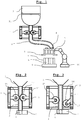
- Fig. 1 a filling system according to the invention is shown schematically.
- the reciprocal hose pump 1 is arranged on a hose 2, which is connected at its inlet end to the bottom of the container 3 and at its outlet end to the filler neck 4 of the filling element 5.
- the filling nozzle 4 opens into the cavity 6 to be filled of a component 7, in particular a hollow chamber brick or hollow brick.
- Per cavity to be filled 6 is advantageously at least one tube 2 with reciprocal hose pump 1 available, the reciprocal peristaltic pumps 1 of the different tubes 2 are operated at different void size with different stroke, or the hoses 2 have a different cross-section. Likewise, it would be possible with several hoses 2 to promote in a cavity 6, or to distribute the funded with a stroke volume of a hose 2 to two or more cavities 6.
- the filling element 5 may have a closure element 8 for closing the filler neck 4 to prevent leakage of foam material between the filling operations.
- a closure element 8 is mounted directly on the filler neck 4, or closes the outlet opening, dripping is prevented. If, however, as known from the prior art on the hose 2, a closure device is present, for example in the form of a device for clamping the tube 2, it comes as already described for dripping by expansion of the foam in the area after the clamping.
- a closure device or closure element 8 are suitable in addition to valves and slides all other known in the prior art devices for selectively opening and closing an outlet opening.
- the components 7 are preferably moved with a transport device, in particular a conveyor belt 9, relative to the filling device.
- the filling element 5 can relative to the transport device or be kept movable to the filling plant, for example, on the arm of an industrial robot 10 or by one or more linear drives in the x, y, and / or z direction.
- the relative movement of the filling element 5 is made possible in that in each case a flexible hose line runs between the reciprocal hose pump 1 and the filler neck 4, preferably in that each hose 2 extends continuously from the container 3 to the filling element 5 or the filler neck 4.
- a less preferred variant would be to provide further lines, for example in the form of pipes or hoses, which extend between the container 3 and the reciprocal hose pump 1 and / or between the reciprocal hose pump 1 and the filling element 5.
- the filling element 5 preferably has a carrier in which the filler neck 4 are fixed or fixable in position according to the position of the cavities 6 of the component 7, in particular block, wherein the position of the filler neck 4 is changeable in the carrier, or the carrier with a carrier is replaceable with other Grestutzenan für assupra.
- the filling element 5 may have at least one switching element, preferably in the form of a three-way valve, or a linear slide plate, to which at least one line coming from the reciprocal hose pump 1, in particular a hose 2, and at least one filler neck 4 are connected.
- an agitator 11 is preferably attached, which keeps the foam to be filled in motion in order to prevent deposition or hardening on the container wall.
- FIGS. 2 and 3 is the reciprocal hose pump 1 shown in detail, in which the hose 2 is guided vertically by the reciprocal hose pump 1.
- the reciprocal hose pump 1 consists of a frame 12 which has a guide for a vertically movable carriage 13.
- the tube 2 is preferably fixed at the upper end of the frame 12 and at the lower end of the frame 12 in its position.
- On the carriage 13 are two rollers 14, 15 opposite each other on both sides of the hose 2 attached.
- the rollers 14, 15 are each mounted on its axis, so that they roll on the hose 2, to keep the stress of the hose 2 low.
- the hose 2 is the reciprocal hose pump 1 shown in the dispensing process, in which the hose 2 is so strongly squeezed by the small distance between the rollers 14, 15 that no or hardly material the hose 2 between the two rollers 14, 15 can happen.
- the rollers 14, 15 Upon downward movement of the carriage 13, the rollers 14, 15 are moved synchronously downwards, whereby the material in the tube 2 is pushed down out of this. Above the rollers 14, 15 material is sucked from the container 3 into the tube 2.
- the way the two rollers 14, 15 cover during application determines the discharge rate per cycle. When the lowest point of the path is reached, as in Fig.
- the cleaning can take place in that cleaning fluid is passed through the hose 2 and / or mechanically cleaned with a hose brush and / or the hose 2 is deformed by the action of force from the outside, for example by tapping with a hammer.
- the filling device shown can be used in foams, the flowability is so low that they would not flow alone through gravity due to the hose 2.
- the outlet of the hose 2 are closed over, for example, a slide.
- the closure element 8 of the respective tube 2 or filling nozzle 4 and the adjustment of the roller 14 mechanically, electrically, pneumatically or hydraulically coupled, so that the moving away of the roller 14 from the tube 2 and the closure with the closure element 8 takes place at the same time.
- the adjusting devices of the roller 14 and the closure element 8 are single-acting hydraulic or pneumatic cylinders, wherein both cylinders can be acted upon by a common control valve with pressure. For example, when pressure is applied, the roller 14 is moved against the hose 2 by the cylinder against a spring force, and the closure element 8 is opened counter to a spring force.
- the orientation of the hose 2 may be arbitrary, for example, horizontal or oblique, a promotion vertically upwards is possible. Less preferably one can not perform the stop as a roller 15, but for example as a surface against which the hose 2, so that it is squeezed between the surface and roller 14. Instead of as in Fig. 3 shown the roller 14 wegzuschwenken from the tube 2, this can also be moved away from the tube 2 translationally. It may also be provided that the roller 15 is not as in FIGS. 2 and 3 is shown, assumes a fixed position, but that both rollers 14, 15 are moved away from the tube 2. The movement of the roller 14 and / or the roller 15 or any other stop towards and / or away from the hose 2 can be effected via a mechanical, electromechanical, magnetic, pneumatic or hydraulic adjusting device.
- a reciprocal hose pump 1 for example, per hose 2, which runs from the container 3 to the filling element 5, a reciprocal hose pump 1 according to FIGS. 2 and 3 available.
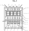
- a plurality of tubes 2 can be provided with a reciprocal hose pump 1 according to the invention, wherein the frame 12 per hose 2 an adjustable roller 14 and a stationary roller 15 are provided on the carriage 13, wherein the rollers 14, as shown, may be arranged parallel to each other.
- a roller 14 acts on a plurality of tubes 2, in which case the delivery rate of the four tubes 2 shown is uniform, unless it hoses 2 are used with different sized cross-sectional area.
- a cycle consisting of an up and a down movement of the carriage 13 thus eight hoses 2 could be emptied simultaneously.
- a reciprocating hose pump 1 according to the invention is shown, which per hose 2 has an adjustable roller 14, wherein the rollers 14 are arranged one after the other in the longitudinal direction.
- the rollers 14 can be brought independently of each other to the respective tube 2, or moved away from it, so that different quantities per tube 2 can be promoted in a cycle by the rollers 14 during the downward movement of the carriage 13 are kept in that position for different lengths, in which they squeeze the tube 2.
- Fig. 6 as a side view of Fig. 4
- a cycle consisting of an up and a down movement of the carriage 13 thus eight hoses 2 simultaneously emptied, the amount of emptying for each hose 2 is individually controllable or regulated.
- the filling plant can be placed in the form of a container 3 and the reciprocal hose pump 1 according to the invention directly above a conveyor belt 9, so that the components 7 directly under the filler 4 and the openings the hoses 2 can be moved so that the foam to be filled is conveyed on a direct vertical path from the container 3 into the components 7.
- the filler neck 4 are shown as shown by a filling element 5. This may be movably supported relative to the frame 12 to allow for accurate positioning over the component 7 or to follow movement of the component 7 on the conveyor belt 9 during the filling process. If the components 7 are moved in exact position and orientation under the filling line and the conveyor belt 9 stops on reaching the desired position, the filler neck 4 may be mounted in a fixed position on the frame 12.
- the filling nozzles 4 can have a common closure element 8, or can be closed individually by a closure element 8 assigned to the respective filler neck 4. If the filling system is to be used to fill different components 7, it can be provided that the filling nozzles 4 can be positioned individually or in groups, or the filling element has 5 valves in order to be able to supply the material flow from a hose 2 to different filler nozzles 4.
- the filler neck 4 can be lowered into the cavities 6 and are moved out of these during the filling process.
- the preferred filling method for cavities 6 with different volumes is based on the Fig. 6 described.
- the component 7 of Fig. 6 has four cavities 6, wherein the two middle cavities 6 are larger than the two outer cavities and, for example, have twice the volume.
- Each cavity 6 is filled with a tube 2, wherein on each tube 2, a roller 14 acts and the rollers 14 are mounted on a common carriage 13. At the upper starting point of the movement of the carriage 13, all rollers 14 are moved up to the stop, so that all hoses 6 are disconnected. The carriage 13 is moved down until the two middle cavities 6 are filled, wherein the two outer rollers 14 are pivoted away from the respective tube 2 as soon as the two outer cavities 6 are full, ie when half the distance has been reached.
- the two middle rollers 14 are moved away from the respective tubes 2 and the carriage 13 is brought back into the upper position.
- the two central rollers 14 squeeze the respective tubes 2 and the two outer rollers 14 are moved up to the respective tubes 2 only when half the distance is reached.
- leading through the reciprocal hose pump 1 hoses 2 can also be attached to different containers 3 and thus can accommodate different media.
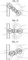
- a rotary tube pump 1 according to the invention
- a hose pump 1 according to the invention is shown in three representations, each with a different orientation of the rotor 16.
- On the rotor 16 for example, two roller 14 are mounted, which are moved upon rotation of the rotor 16 along a circular path.
- the hose 2 can, as in the left part of the Fig.
- roller 14 is pressed by the actuator against a spring force with a defined force to the outside, so that the tube 2 is crushed during movement of the roller 14 along its longitudinal direction between the roller 14 and the stopper with a defined force, as in the Fig. 7a and 7b shown. If the force is removed by the actuator, the roller 14 is moved away by the spring force from the tube 2, so that it is no longer squeezed between the roller 14 and the stop, as it is in Fig.
- Fig. 7c the rotor 16 is shown in dashed lines in that position, which the roller 14 has long been possible to cover in crimped contact with the straight tube 2.
- rotor 16 shown with solid lines the roller 14 is already moved away from the tube 2 before reaching this position, so that a correspondingly lower volume is promoted.
- the tube 2 is shown dotted, in which case the tube 2 is arranged in a circular arc along the orbit of the roller 14, so that the roller 14 is in contact with the tube 2 longer per revolution of the rotor 16.
- a likewise arcuate stop (not shown).
- the hose pump 1 of the invention can Fig. 7a-c So also how an ordinary peristaltic pump 1 are operated when both rollers 14 constantly remain in the outer position, whereby the peristaltic pump 1 promotes quasi-continuous.
- Fig. 7b the rotor 16 shown in dashed lines in the vertical position, with two rollers 14 in the outer position of the tube 2 squeezing position.
- the hose 2 is in this mode of operation, as in a conventional peristaltic pump, at any time by at least one of the rollers 14 clamped.
- the discharge rate can thus be controlled at a constant speed of the rotor 16 over the frequency and the duration of those periods, which cover the rollers 14 by pressing the adjusting device in crimped contact with the tube 2.
- the squeezing effect can be taken at any time from the tube 2, so that when a cavity 6 is completely filled with foam, the squeezing effect can be removed immediately and is only restored to fill the next cavity 6.
- the rotor 16 does not have to be stopped.
- a particularly valuable peristaltic pump 1 according to the invention Fig. 7a-c results when a plurality of rollers 14 and roller pairs are successively mounted along the axis of the rotor 16 on this and each of these rollers 14 and each roller pair acts on its own tube 2 and has its own adjusting device, so that each roller 14 or each Roller pair can be moved independently of the other rollers 14 and roller pairs to the respective tube 2, so that the delivered volume per tube 2 is independent of the other hoses 2 controllable. Since all rolls 14 or pairs of rolls are moved by a common rotor 16, a simple compact device results, for controlled filling or metering with several hoses 2.
- the number of mounted on the rotor 16 rollers 14, which act on a hose 2 does not have to be two as shown, for example, it can be mounted on the rotor 16, for example, only one roller 14.
- three, four or more rollers 14 act on a hose 2, which advantageously evenly, ie each present at the same angle to each other on the rotor 16 and each roller 14 has an adjusting device with which the radial distance from the axis of rotation of the rotor 16 is controllable or changeable. It may be sufficient if an adjusting device is present, which controls the distance of all rollers 14, which act on a hose 2, uniformly or changes.
Landscapes
- Engineering & Computer Science (AREA)
- Mechanical Engineering (AREA)
- General Engineering & Computer Science (AREA)
- Structural Engineering (AREA)
- Chemical & Material Sciences (AREA)
- Ceramic Engineering (AREA)
- Reciprocating Pumps (AREA)
Claims (15)
- Utilisation d'une pompe péristaltique réciproque (1) dans un dispositif de remplissage comprenant un réservoir (3), qui est rempli au moins en partie de matériau à remplir et présente au moins une ouverture et un élément de remplissage (5) avec au moins un bec de remplissage (4), où une conduite s'étendant entre une ouverture du réservoir (3) et l'élément de remplissage (5) est réalisée au moins en partie sous forme de tuyau (2) et comporte sur cette partie de tuyau la pompe péristaltique réciproque (1), qui comporte un chariot mobile dans la direction longitudinale du tuyau (2), sur lequel est fixé un rouleau rotatif (14), le chariot (13) pouvant être déplacé cycliquement le long du tuyau (2) dans des directions opposées, le tuyau (2) étant comprimé au moins en partie entre le rouleau (14) et une butée lors du déplacement du chariot (13) dans la première direction, le rouleau (14) ou la butée étant poussé(e) contre le tuyau (2) par un dispositif de réglage et n'étant pas comprimé entre le rouleau (14) et la butée lors du déplacement dans la deuxième direction, caractérisée en ce que une mousse isolante minérale auto-durcissante est acheminée par la pompe péristaltique réciproque (1) dans la cavité (6) d'un matériau de construction ou d'un élément de construction (7) et où le débit lors d'un déplacement du rouleau (14) est commandé du point de départ au point d'arrivée dans le sens longitudinal du tuyau (2), le tuyau (2) étant comprimé par l'actionnement du dispositif de réglage du tuyau (2) seulement sur une partie de ce déplacement.
- Utilisation selon la revendication 1, caractérisée en ce que la mousse isolante est une mousse minérale auto-durcissante présentant une proportion de pores d'au moins 50 %.
- Utilisation d'une pompe péristaltique réciproque (1) dans un dispositif de remplissage selon la revendication 1, caractérisée en ce que le parcours à travers le tuyau (2) de l'admission de la pompe péristaltique réciproque (1) jusqu'à l'orifice de sortie de la mousse sur le bec de remplissage (4) est libre lorsque le tuyau (2) n'est pas comprimé entre le rouleau (14) et la butée.
- Utilisation d'une pompe péristaltique réciproque (1) dans un dispositif de remplissage selon les revendications 1 à 3, caractérisée en ce que au moins une conduite en plus du segment de tuyau sur lequel la pompe péristaltique réciproque (1) est agencée, comporte un autre segment de tuyau de façon à ce que le bec de remplissage (4) ou l'élément de remplissage (5) soit déplaçable par rapport au réservoir (3).
- Utilisation d'une pompe péristaltique réciproque (1) dans un dispositif de remplissage selon la revendication 4, caractérisée en ce que le bec de remplissage (4) ou l'élément de remplissage (5) est positionné au-dessus des cavités (6) d'un robot industriel ou d'un robot doté d'actionneurs linéaires au moins dans les directions x et y.
- Utilisation d'une pompe péristaltique réciproque (1) dans un dispositif de remplissage selon la revendication 5, caractérisée en ce que le bec de remplissage (4) ou l'élément de remplissage (5) est incliné dans la cavité à remplir (6) et sorti de celle-ci pendant le remplissage.
- Utilisation d'une pompe péristaltique réciproque (1) dans un dispositif de remplissage selon les revendications 1 à 6, caractérisée en ce que la butée est un rouleau rotatif (15) fixé au chariot mobile (13).
- Utilisation d'une pompe péristaltique réciproque (1) dans un dispositif de remplissage selon les revendications 1 à 7, caractérisée en ce que la pompe péristaltique réciproque (1) comporte un dispositif de réglage à l'aide duquel la distance du rouleau (14) par rapport à la butée peut être déterminée.
- Utilisation d'une pompe péristaltique réciproque (1) dans un dispositif de remplissage selon les revendications 1 à 8, caractérisée en ce que le procédé est utilisé selon une des revendications 10 à 15 pour le contrôle du débit de la pompe péristaltique réciproque (1).
- Procédé de contrôle du débit d'une pompe péristaltique réciproque (1), qui comporte au moins un rouleau rotatif (14), qui est déplacé cycliquement le long d'au moins un tuyau (2) d'un point de départ sur le tuyau (2) à un point d'arrivée sur le tuyau (2), le tuyau (2) étant comprimé lors du déplacement du rouleau (14) dans la direction longitudinale du tuyau (2) du point de départ au point d'arrivée au moins temporairement entre le rouleau (14) et une butée, le rouleau (14) ou la butée étant poussé(e) par un dispositif de réglage contre le tuyau (2) et le tuyau (2) n'étant pas comprimé lors du déplacement du rouleau (14) de retour au point de départ entre le rouleau (14) et la butée, caractérisé en ce que le débit acheminé est contrôlé pendant un déplacement du rouleau (14) du point de départ au point d'arrivée dans la direction longitudinale du tuyau (2), le tuyau (2) étant comprimé seulement sur une partie de ce déplacement suite à la commande du dispositif de réglage.
- Procédé selon la revendication 10, caractérisé en ce que la pompe péristaltique réciproque (1) comporte plusieurs rouleaux rotatifs (14), chaque rouleau (14) agissant sur son propre tuyau (2), les rouleaux (14) d'un entraînement commun étant déplacés cycliquement le long des tuyaux (2) d'un point de départ sur chaque tuyau (2) vers un point d'arrivée sur chaque tuyau (2), chaque tuyau (2) étant comprimé lors du déplacement de son rouleau (14) dans la direction longitudinale du tuyau (2) du point de départ au point d'arrivée dans une zone contrôlée individuellement de ce déplacement entre son rouleau (14) et sa butée, chaque rouleau (14) ou chaque butée étant comprimé(e) contre le tuyau (2) par son propre dispositif de réglage commandé individuellement.
- Procédé selon les revendications 10 à 11, caractérisé en ce que au moins un tuyau (2) chemine de façon rectiligne à travers la pompe péristaltique réciproque (1) et le rouleau (14) est déplacé par contact par compression le long du tuyau (2).
- Procédé selon les revendications 10 à 11, caractérisé en ce que un rotor (16) fait pivoter au moins un rouleau (14) et au moins un tuyau (2) s'étend selon un arc de cercle autour de l'axe du rotor (16), chaque rouleau (14) monté sur le rotor (16) se déplaçant en arc de cercle du point de départ au point d'arrivée du tuyau (2), chaque rouleau (14) sur le rotor (16) comportant un dispositif de réglage, qui actionne la partie du chemin que le rouleau (14) parcourt par contact par compression avec le tuyau (2) dans les limites du déplacement du point de départ au point d'arrivée.
- Procédé selon les revendications 10 à 13, caractérisé en ce que l'actionnement, commandé de façon programmée, de chaque dispositif de réglage, avec lequel un rouleau (14) ou une butée est comprimé(e) contre un tuyau (2), s'effectue électriquement, pneumatiquement ou hydrauliquement.
- Procédé selon les revendications 10 à 14, caractérisé en ce que chaque dispositif de réglage, avec lequel un rouleau (14) ou une butée est comprimé(e) contre un tuyau (2), interagit avec un élément de fermeture (8) de façon à ce que le tuyau (2) ou la conduite se raccordant à ce dernier au moment où le tuyau (2) n'est pas comprimé entre le rouleau (14) et la butée, est fermé(e) à un autre endroit par l'élément de fermeture (8).
Applications Claiming Priority (1)
| Application Number | Priority Date | Filing Date | Title |
|---|---|---|---|
| AT509672015 | 2015-11-12 |
Publications (2)
| Publication Number | Publication Date |
|---|---|
| EP3168472A1 EP3168472A1 (fr) | 2017-05-17 |
| EP3168472B1 true EP3168472B1 (fr) | 2019-01-02 |
Family
ID=57256178
Family Applications (1)
| Application Number | Title | Priority Date | Filing Date |
|---|---|---|---|
| EP16197874.7A Active EP3168472B1 (fr) | 2015-11-12 | 2016-11-09 | Installation de remplissage pour mousse isolante minérale |
Country Status (1)
| Country | Link |
|---|---|
| EP (1) | EP3168472B1 (fr) |
Families Citing this family (7)
| Publication number | Priority date | Publication date | Assignee | Title |
|---|---|---|---|---|
| CN107246379A (zh) * | 2017-07-21 | 2017-10-13 | 长沙执先智量科技股份有限公司 | 一种直线式高精度蠕动泵 |
| CN209083527U (zh) * | 2018-09-30 | 2019-07-09 | 长沙执先智量科技股份有限公司 | 一种用于蠕动泵的双滚轮压管装置 |
| CN109098956B (zh) * | 2018-09-30 | 2024-04-26 | 湖南执先科技有限公司 | 一种直线式洁净蠕动计量泵 |
| CN110043454B (zh) * | 2019-03-29 | 2025-04-29 | 湖南执先科技有限公司 | 一种中心带气缸压管的双滚轮蠕动泵 |
| CN110774429B (zh) * | 2019-11-29 | 2021-07-16 | 佛山森蒂泰珂科技有限公司 | 一种齿轮驱动式瓷砖生产用高效喷釉设备 |
| CN110925176B (zh) * | 2019-12-26 | 2024-04-26 | 湖南执先科技有限公司 | 一种双滚轮旋转式高精度蠕动泵 |
| CN112078847A (zh) * | 2020-08-28 | 2020-12-15 | 湖南执先科技有限公司 | 一种智能灌装方法及系统 |
Family Cites Families (7)
| Publication number | Priority date | Publication date | Assignee | Title |
|---|---|---|---|---|
| US4529106A (en) * | 1982-09-02 | 1985-07-16 | Broadfoot John T | Metering and/or feeding unit for fluid materials |
| AT389909B (de) * | 1983-12-12 | 1990-02-26 | Leier Michael | Baustein |
| DE4008705A1 (de) * | 1990-03-17 | 1991-09-19 | Varta Batterie | Vorrichtung zum einfuehren von viskosen aktiven inhaltsstoffen in das gehaeuse eines galvanischen elements |
| US5380172A (en) * | 1993-12-29 | 1995-01-10 | Ulbing; Otmar | Peristaltic action precision pump filler |
| US20060228240A1 (en) * | 2005-03-30 | 2006-10-12 | Lancer Partnership, Ltd. | Method and apparatus for a linear peristaltic pump |
| WO2009130250A1 (fr) * | 2008-04-22 | 2009-10-29 | Trepko A/S | Appareil de distribution péristaltique linéaire et procédé destiné à être utilisé dans l'appareil |
| DE202014100309U1 (de) * | 2014-01-24 | 2015-02-05 | Ziegelwerk Otto Staudacher Gmbh & Co. Kg | Fülleinrichtung zum Befüllen von Mauersteinen |
-
2016
- 2016-11-09 EP EP16197874.7A patent/EP3168472B1/fr active Active
Non-Patent Citations (1)
| Title |
|---|
| None * |
Also Published As
| Publication number | Publication date |
|---|---|
| EP3168472A1 (fr) | 2017-05-17 |
Similar Documents
| Publication | Publication Date | Title |
|---|---|---|
| EP3168472B1 (fr) | Installation de remplissage pour mousse isolante minérale | |
| EP1427536A1 (fr) | Dispositif pour transporter de la poudre et procede pour le faire fonctionner | |
| DE3420222C2 (fr) | ||
| EP3307516B1 (fr) | Procédé ainsi que dispositif de production d'un récipient rempli et fermé | |
| WO2010092535A1 (fr) | Procédé, commande, agencement de vannes et dispositif de formation de portions pour le portionnement d'une pâte fluide, éventuellement mise sous pression | |
| DE2139131A1 (de) | Verfahren zur dosierbaren Forderung von Materialien und Einrichtung zur Aus fuhrung des Verfahrens | |
| DE20307518U1 (de) | Schlauchmischer zum Vermischen von pastösen Massen oder Flüssigkeiten aus mindestens zwei Komponenten und Aufnahmebehälter der Komponenten | |
| EP0403813B1 (fr) | Procédé et dispositif pour le remplissage dosé de produits liquides et pâteux, notamment de produits alimentaires ou autres semblables | |
| EP3732975B1 (fr) | Séparateur du flux de remplissage | |
| EP2465655B1 (fr) | Procédé de vidage d'un silo de grue développé pour la réception et le transport suspendu de matériaux de construction coulants | |
| EP3277955B1 (fr) | Procédé pour remplir de cavités de briques | |
| CH632459A5 (de) | Vorrichtung zum einfuellen einer dosierten menge von fliessfaehigem gut in eine verpackung. | |
| DE3802548A1 (de) | Verfahren und vorrichtung zum aufbringen viskoser massen auf ortsfeste unterlagen | |
| EP0401510B1 (fr) | Dispositif pour remplir des emballages de produits pouvant s'écouler | |
| DE2032717A1 (de) | Maschine zum Portionieren und Abfüllen von flussigen oder pastosen Massen | |
| DE1966542B2 (de) | Anlage zur verarbeitung von giessharz | |
| AT515751B1 (de) | Vorrichtung und Verfahren zur dosierten Abgabe pumpfähiger Massen | |
| DE69208461T2 (de) | Gerät zum Abgeben einer definierten Flüssigkeitsmenge | |
| DE3504107A1 (de) | Hydraulisches dosier- und foerdersystem | |
| EP3292306A2 (fr) | Flexible élastique de pompe péristaltique, pompe péristaltique servant à refouler des matières coulantes ou de la poudre, unité servant à former des portions de matières coulantes ou de poudre, système comprenant plusieurs unités de ce type, procédé pour former des portions de matières coulantes ou de poudre | |
| DE2248235C2 (de) | Vorrichtung zum Austragen von Schaummassen und ähnlichen empfindlichen Massen in Teilmengen | |
| DE2904519A1 (de) | Dosier- und austeilvorrichtung fuer teigiges gut, insbesondere von der bei der herstellung von suppenwuerfeln verwendeten art | |
| EP1590586A1 (fr) | Soupape pour le transvasement en cadence de produits d'un recipient d'alimentation dans des recipients d'emballage | |
| DE1486018B1 (de) | Vorrichtung zur gleichzeitigen Abfuellung bestimmter Mengen fliessfaehiger Stoffe in mehrere Behaelter | |
| WO2016005258A1 (fr) | Élément de remplissage et machine de remplissage |
Legal Events
| Date | Code | Title | Description |
|---|---|---|---|
| PUAI | Public reference made under article 153(3) epc to a published international application that has entered the european phase |
Free format text: ORIGINAL CODE: 0009012 |
|
| STAA | Information on the status of an ep patent application or granted ep patent |
Free format text: STATUS: THE APPLICATION HAS BEEN PUBLISHED |
|
| AK | Designated contracting states |
Kind code of ref document: A1 Designated state(s): AL AT BE BG CH CY CZ DE DK EE ES FI FR GB GR HR HU IE IS IT LI LT LU LV MC MK MT NL NO PL PT RO RS SE SI SK SM TR |
|
| AX | Request for extension of the european patent |
Extension state: BA ME |
|
| STAA | Information on the status of an ep patent application or granted ep patent |
Free format text: STATUS: REQUEST FOR EXAMINATION WAS MADE |
|
| 17P | Request for examination filed |
Effective date: 20171114 |
|
| RBV | Designated contracting states (corrected) |
Designated state(s): AL AT BE BG CH CY CZ DE DK EE ES FI FR GB GR HR HU IE IS IT LI LT LU LV MC MK MT NL NO PL PT RO RS SE SI SK SM TR |
|
| STAA | Information on the status of an ep patent application or granted ep patent |
Free format text: STATUS: EXAMINATION IS IN PROGRESS |
|
| 17Q | First examination report despatched |
Effective date: 20171220 |
|
| GRAP | Despatch of communication of intention to grant a patent |
Free format text: ORIGINAL CODE: EPIDOSNIGR1 |
|
| STAA | Information on the status of an ep patent application or granted ep patent |
Free format text: STATUS: GRANT OF PATENT IS INTENDED |
|
| INTG | Intention to grant announced |
Effective date: 20180720 |
|
| GRAS | Grant fee paid |
Free format text: ORIGINAL CODE: EPIDOSNIGR3 |
|
| GRAA | (expected) grant |
Free format text: ORIGINAL CODE: 0009210 |
|
| STAA | Information on the status of an ep patent application or granted ep patent |
Free format text: STATUS: THE PATENT HAS BEEN GRANTED |
|
| AK | Designated contracting states |
Kind code of ref document: B1 Designated state(s): AL AT BE BG CH CY CZ DE DK EE ES FI FR GB GR HR HU IE IS IT LI LT LU LV MC MK MT NL NO PL PT RO RS SE SI SK SM TR |
|
| REG | Reference to a national code |
Ref country code: GB Ref legal event code: FG4D Free format text: NOT ENGLISH |
|
| REG | Reference to a national code |
Ref country code: CH Ref legal event code: EP Ref country code: AT Ref legal event code: REF Ref document number: 1084717 Country of ref document: AT Kind code of ref document: T Effective date: 20190115 |
|
| REG | Reference to a national code |
Ref country code: IE Ref legal event code: FG4D Free format text: LANGUAGE OF EP DOCUMENT: GERMAN |
|
| REG | Reference to a national code |
Ref country code: DE Ref legal event code: R096 Ref document number: 502016003058 Country of ref document: DE |
|
| REG | Reference to a national code |
Ref country code: NL Ref legal event code: MP Effective date: 20190102 |
|
| REG | Reference to a national code |
Ref country code: LT Ref legal event code: MG4D |
|
| PG25 | Lapsed in a contracting state [announced via postgrant information from national office to epo] |
Ref country code: NL Free format text: LAPSE BECAUSE OF FAILURE TO SUBMIT A TRANSLATION OF THE DESCRIPTION OR TO PAY THE FEE WITHIN THE PRESCRIBED TIME-LIMIT Effective date: 20190102 |
|
| PG25 | Lapsed in a contracting state [announced via postgrant information from national office to epo] |
Ref country code: SE Free format text: LAPSE BECAUSE OF FAILURE TO SUBMIT A TRANSLATION OF THE DESCRIPTION OR TO PAY THE FEE WITHIN THE PRESCRIBED TIME-LIMIT Effective date: 20190102 Ref country code: LT Free format text: LAPSE BECAUSE OF FAILURE TO SUBMIT A TRANSLATION OF THE DESCRIPTION OR TO PAY THE FEE WITHIN THE PRESCRIBED TIME-LIMIT Effective date: 20190102 Ref country code: FI Free format text: LAPSE BECAUSE OF FAILURE TO SUBMIT A TRANSLATION OF THE DESCRIPTION OR TO PAY THE FEE WITHIN THE PRESCRIBED TIME-LIMIT Effective date: 20190102 Ref country code: NO Free format text: LAPSE BECAUSE OF FAILURE TO SUBMIT A TRANSLATION OF THE DESCRIPTION OR TO PAY THE FEE WITHIN THE PRESCRIBED TIME-LIMIT Effective date: 20190402 Ref country code: PT Free format text: LAPSE BECAUSE OF FAILURE TO SUBMIT A TRANSLATION OF THE DESCRIPTION OR TO PAY THE FEE WITHIN THE PRESCRIBED TIME-LIMIT Effective date: 20190502 Ref country code: ES Free format text: LAPSE BECAUSE OF FAILURE TO SUBMIT A TRANSLATION OF THE DESCRIPTION OR TO PAY THE FEE WITHIN THE PRESCRIBED TIME-LIMIT Effective date: 20190102 Ref country code: PL Free format text: LAPSE BECAUSE OF FAILURE TO SUBMIT A TRANSLATION OF THE DESCRIPTION OR TO PAY THE FEE WITHIN THE PRESCRIBED TIME-LIMIT Effective date: 20190102 |
|
| PG25 | Lapsed in a contracting state [announced via postgrant information from national office to epo] |
Ref country code: IS Free format text: LAPSE BECAUSE OF FAILURE TO SUBMIT A TRANSLATION OF THE DESCRIPTION OR TO PAY THE FEE WITHIN THE PRESCRIBED TIME-LIMIT Effective date: 20190502 Ref country code: GR Free format text: LAPSE BECAUSE OF FAILURE TO SUBMIT A TRANSLATION OF THE DESCRIPTION OR TO PAY THE FEE WITHIN THE PRESCRIBED TIME-LIMIT Effective date: 20190403 Ref country code: HR Free format text: LAPSE BECAUSE OF FAILURE TO SUBMIT A TRANSLATION OF THE DESCRIPTION OR TO PAY THE FEE WITHIN THE PRESCRIBED TIME-LIMIT Effective date: 20190102 Ref country code: RS Free format text: LAPSE BECAUSE OF FAILURE TO SUBMIT A TRANSLATION OF THE DESCRIPTION OR TO PAY THE FEE WITHIN THE PRESCRIBED TIME-LIMIT Effective date: 20190102 Ref country code: LV Free format text: LAPSE BECAUSE OF FAILURE TO SUBMIT A TRANSLATION OF THE DESCRIPTION OR TO PAY THE FEE WITHIN THE PRESCRIBED TIME-LIMIT Effective date: 20190102 Ref country code: BG Free format text: LAPSE BECAUSE OF FAILURE TO SUBMIT A TRANSLATION OF THE DESCRIPTION OR TO PAY THE FEE WITHIN THE PRESCRIBED TIME-LIMIT Effective date: 20190402 |
|
| REG | Reference to a national code |
Ref country code: DE Ref legal event code: R097 Ref document number: 502016003058 Country of ref document: DE |
|
| PG25 | Lapsed in a contracting state [announced via postgrant information from national office to epo] |
Ref country code: RO Free format text: LAPSE BECAUSE OF FAILURE TO SUBMIT A TRANSLATION OF THE DESCRIPTION OR TO PAY THE FEE WITHIN THE PRESCRIBED TIME-LIMIT Effective date: 20190102 Ref country code: CZ Free format text: LAPSE BECAUSE OF FAILURE TO SUBMIT A TRANSLATION OF THE DESCRIPTION OR TO PAY THE FEE WITHIN THE PRESCRIBED TIME-LIMIT Effective date: 20190102 Ref country code: EE Free format text: LAPSE BECAUSE OF FAILURE TO SUBMIT A TRANSLATION OF THE DESCRIPTION OR TO PAY THE FEE WITHIN THE PRESCRIBED TIME-LIMIT Effective date: 20190102 Ref country code: DK Free format text: LAPSE BECAUSE OF FAILURE TO SUBMIT A TRANSLATION OF THE DESCRIPTION OR TO PAY THE FEE WITHIN THE PRESCRIBED TIME-LIMIT Effective date: 20190102 Ref country code: SK Free format text: LAPSE BECAUSE OF FAILURE TO SUBMIT A TRANSLATION OF THE DESCRIPTION OR TO PAY THE FEE WITHIN THE PRESCRIBED TIME-LIMIT Effective date: 20190102 Ref country code: AL Free format text: LAPSE BECAUSE OF FAILURE TO SUBMIT A TRANSLATION OF THE DESCRIPTION OR TO PAY THE FEE WITHIN THE PRESCRIBED TIME-LIMIT Effective date: 20190102 |
|
| PLBE | No opposition filed within time limit |
Free format text: ORIGINAL CODE: 0009261 |
|
| STAA | Information on the status of an ep patent application or granted ep patent |
Free format text: STATUS: NO OPPOSITION FILED WITHIN TIME LIMIT |
|
| PG25 | Lapsed in a contracting state [announced via postgrant information from national office to epo] |
Ref country code: SM Free format text: LAPSE BECAUSE OF FAILURE TO SUBMIT A TRANSLATION OF THE DESCRIPTION OR TO PAY THE FEE WITHIN THE PRESCRIBED TIME-LIMIT Effective date: 20190102 |
|
| 26N | No opposition filed |
Effective date: 20191003 |
|
| PG25 | Lapsed in a contracting state [announced via postgrant information from national office to epo] |
Ref country code: SI Free format text: LAPSE BECAUSE OF FAILURE TO SUBMIT A TRANSLATION OF THE DESCRIPTION OR TO PAY THE FEE WITHIN THE PRESCRIBED TIME-LIMIT Effective date: 20190102 |
|
| REG | Reference to a national code |
Ref country code: CH Ref legal event code: NV Representative=s name: DENNEMEYER AG, CH |
|
| PG25 | Lapsed in a contracting state [announced via postgrant information from national office to epo] |
Ref country code: TR Free format text: LAPSE BECAUSE OF FAILURE TO SUBMIT A TRANSLATION OF THE DESCRIPTION OR TO PAY THE FEE WITHIN THE PRESCRIBED TIME-LIMIT Effective date: 20190102 |
|
| PG25 | Lapsed in a contracting state [announced via postgrant information from national office to epo] |
Ref country code: LU Free format text: LAPSE BECAUSE OF NON-PAYMENT OF DUE FEES Effective date: 20191109 Ref country code: MC Free format text: LAPSE BECAUSE OF FAILURE TO SUBMIT A TRANSLATION OF THE DESCRIPTION OR TO PAY THE FEE WITHIN THE PRESCRIBED TIME-LIMIT Effective date: 20190102 |
|
| REG | Reference to a national code |
Ref country code: BE Ref legal event code: MM Effective date: 20191130 |
|
| PG25 | Lapsed in a contracting state [announced via postgrant information from national office to epo] |
Ref country code: BE Free format text: LAPSE BECAUSE OF NON-PAYMENT OF DUE FEES Effective date: 20191130 |
|
| PG25 | Lapsed in a contracting state [announced via postgrant information from national office to epo] |
Ref country code: CY Free format text: LAPSE BECAUSE OF FAILURE TO SUBMIT A TRANSLATION OF THE DESCRIPTION OR TO PAY THE FEE WITHIN THE PRESCRIBED TIME-LIMIT Effective date: 20190102 |
|
| PG25 | Lapsed in a contracting state [announced via postgrant information from national office to epo] |
Ref country code: HU Free format text: LAPSE BECAUSE OF FAILURE TO SUBMIT A TRANSLATION OF THE DESCRIPTION OR TO PAY THE FEE WITHIN THE PRESCRIBED TIME-LIMIT; INVALID AB INITIO Effective date: 20161109 Ref country code: MT Free format text: LAPSE BECAUSE OF FAILURE TO SUBMIT A TRANSLATION OF THE DESCRIPTION OR TO PAY THE FEE WITHIN THE PRESCRIBED TIME-LIMIT Effective date: 20190102 |
|
| PG25 | Lapsed in a contracting state [announced via postgrant information from national office to epo] |
Ref country code: MK Free format text: LAPSE BECAUSE OF FAILURE TO SUBMIT A TRANSLATION OF THE DESCRIPTION OR TO PAY THE FEE WITHIN THE PRESCRIBED TIME-LIMIT Effective date: 20190102 |
|
| REG | Reference to a national code |
Ref country code: CH Ref legal event code: U11 Free format text: ST27 STATUS EVENT CODE: U-0-0-U10-U11 (AS PROVIDED BY THE NATIONAL OFFICE) Effective date: 20251201 |
|
| REG | Reference to a national code |
Ref country code: DE Ref legal event code: R081 Ref document number: 502016003058 Country of ref document: DE Owner name: MIRALIS GMBH, AT Free format text: FORMER OWNER: GEOLYTH MINERAL TECHNOLOGIE GMBH, TRAUN, AT |
|
| PGFP | Annual fee paid to national office [announced via postgrant information from national office to epo] |
Ref country code: DE Payment date: 20251119 Year of fee payment: 10 |
|
| PGFP | Annual fee paid to national office [announced via postgrant information from national office to epo] |
Ref country code: GB Payment date: 20251120 Year of fee payment: 10 |
|
| PGFP | Annual fee paid to national office [announced via postgrant information from national office to epo] |
Ref country code: AT Payment date: 20251016 Year of fee payment: 10 |
|
| PGFP | Annual fee paid to national office [announced via postgrant information from national office to epo] |
Ref country code: IT Payment date: 20251125 Year of fee payment: 10 |
|
| PGFP | Annual fee paid to national office [announced via postgrant information from national office to epo] |
Ref country code: FR Payment date: 20251126 Year of fee payment: 10 |
|
| PGFP | Annual fee paid to national office [announced via postgrant information from national office to epo] |
Ref country code: CH Payment date: 20251201 Year of fee payment: 10 |
|
| PGFP | Annual fee paid to national office [announced via postgrant information from national office to epo] |
Ref country code: IE Payment date: 20251121 Year of fee payment: 10 |