EP3168472B1 - Filling apparatus for mineral insulating foams - Google Patents
Filling apparatus for mineral insulating foams Download PDFInfo
- Publication number
- EP3168472B1 EP3168472B1 EP16197874.7A EP16197874A EP3168472B1 EP 3168472 B1 EP3168472 B1 EP 3168472B1 EP 16197874 A EP16197874 A EP 16197874A EP 3168472 B1 EP3168472 B1 EP 3168472B1
- Authority
- EP
- European Patent Office
- Prior art keywords
- hose
- roller
- filling
- pump
- reciprocating
- Prior art date
- Legal status (The legal status is an assumption and is not a legal conclusion. Google has not performed a legal analysis and makes no representation as to the accuracy of the status listed.)
- Active
Links
- 239000006260 foam Substances 0.000 title claims description 48
- 229910052500 inorganic mineral Inorganic materials 0.000 title claims description 18
- 239000011707 mineral Substances 0.000 title claims description 18
- 239000000463 material Substances 0.000 claims description 18
- 238000000034 method Methods 0.000 claims description 14
- 239000002937 thermal insulation foam Substances 0.000 claims description 10
- 239000011148 porous material Substances 0.000 claims description 3
- 230000004913 activation Effects 0.000 claims 1
- 239000004035 construction material Substances 0.000 claims 1
- 230000002572 peristaltic effect Effects 0.000 description 47
- 239000000945 filler Substances 0.000 description 15
- 239000006261 foam material Substances 0.000 description 10
- 230000008859 change Effects 0.000 description 9
- 239000004566 building material Substances 0.000 description 7
- 230000000694 effects Effects 0.000 description 5
- 239000012530 fluid Substances 0.000 description 5
- 238000004140 cleaning Methods 0.000 description 4
- 238000011109 contamination Methods 0.000 description 4
- 238000005429 filling process Methods 0.000 description 4
- 235000013305 food Nutrition 0.000 description 4
- 230000001105 regulatory effect Effects 0.000 description 4
- 230000009471 action Effects 0.000 description 3
- 239000011449 brick Substances 0.000 description 3
- 238000005086 pumping Methods 0.000 description 3
- 238000002788 crimping Methods 0.000 description 2
- 239000011464 hollow brick Substances 0.000 description 2
- 230000007246 mechanism Effects 0.000 description 2
- 230000008569 process Effects 0.000 description 2
- 230000001133 acceleration Effects 0.000 description 1
- 230000008901 benefit Effects 0.000 description 1
- 238000005352 clarification Methods 0.000 description 1
- 238000004891 communication Methods 0.000 description 1
- 230000001276 controlling effect Effects 0.000 description 1
- 230000008021 deposition Effects 0.000 description 1
- 238000001514 detection method Methods 0.000 description 1
- 230000003670 easy-to-clean Effects 0.000 description 1
- 235000013399 edible fruits Nutrition 0.000 description 1
- 238000005265 energy consumption Methods 0.000 description 1
- 238000005516 engineering process Methods 0.000 description 1
- 230000007613 environmental effect Effects 0.000 description 1
- 230000007717 exclusion Effects 0.000 description 1
- 230000005484 gravity Effects 0.000 description 1
- 230000036541 health Effects 0.000 description 1
- 238000004519 manufacturing process Methods 0.000 description 1
- 239000011159 matrix material Substances 0.000 description 1
- 235000010746 mayonnaise Nutrition 0.000 description 1
- 239000008268 mayonnaise Substances 0.000 description 1
- 239000012528 membrane Substances 0.000 description 1
- 238000003825 pressing Methods 0.000 description 1
- 238000010079 rubber tapping Methods 0.000 description 1
- 238000003756 stirring Methods 0.000 description 1
- 238000009827 uniform distribution Methods 0.000 description 1
- 239000011800 void material Substances 0.000 description 1
- XLYOFNOQVPJJNP-UHFFFAOYSA-N water Substances O XLYOFNOQVPJJNP-UHFFFAOYSA-N 0.000 description 1
Images

Classifications
-
- F—MECHANICAL ENGINEERING; LIGHTING; HEATING; WEAPONS; BLASTING
- F04—POSITIVE - DISPLACEMENT MACHINES FOR LIQUIDS; PUMPS FOR LIQUIDS OR ELASTIC FLUIDS
- F04B—POSITIVE-DISPLACEMENT MACHINES FOR LIQUIDS; PUMPS
- F04B43/00—Machines, pumps, or pumping installations having flexible working members
- F04B43/12—Machines, pumps, or pumping installations having flexible working members having peristaltic action
- F04B43/1223—Machines, pumps, or pumping installations having flexible working members having peristaltic action the actuating elements, e.g. rollers, moving in a straight line during squeezing
-
- B—PERFORMING OPERATIONS; TRANSPORTING
- B28—WORKING CEMENT, CLAY, OR STONE
- B28B—SHAPING CLAY OR OTHER CERAMIC COMPOSITIONS; SHAPING SLAG; SHAPING MIXTURES CONTAINING CEMENTITIOUS MATERIAL, e.g. PLASTER
- B28B11/00—Apparatus or processes for treating or working the shaped or preshaped articles
- B28B11/04—Apparatus or processes for treating or working the shaped or preshaped articles for coating or applying engobing layers
- B28B11/042—Apparatus or processes for treating or working the shaped or preshaped articles for coating or applying engobing layers with insulating material
- B28B11/043—Apparatus or processes for treating or working the shaped or preshaped articles for coating or applying engobing layers with insulating material filling cavities or chambers of hollow blocks
-
- F—MECHANICAL ENGINEERING; LIGHTING; HEATING; WEAPONS; BLASTING
- F04—POSITIVE - DISPLACEMENT MACHINES FOR LIQUIDS; PUMPS FOR LIQUIDS OR ELASTIC FLUIDS
- F04B—POSITIVE-DISPLACEMENT MACHINES FOR LIQUIDS; PUMPS
- F04B13/00—Pumps specially modified to deliver fixed or variable measured quantities
-
- F—MECHANICAL ENGINEERING; LIGHTING; HEATING; WEAPONS; BLASTING
- F04—POSITIVE - DISPLACEMENT MACHINES FOR LIQUIDS; PUMPS FOR LIQUIDS OR ELASTIC FLUIDS
- F04B—POSITIVE-DISPLACEMENT MACHINES FOR LIQUIDS; PUMPS
- F04B15/00—Pumps adapted to handle specific fluids, e.g. by selection of specific materials for pumps or pump parts
- F04B15/02—Pumps adapted to handle specific fluids, e.g. by selection of specific materials for pumps or pump parts the fluids being viscous or non-homogeneous
- F04B15/023—Pumps adapted to handle specific fluids, e.g. by selection of specific materials for pumps or pump parts the fluids being viscous or non-homogeneous supply of fluid to the pump by gravity through a hopper, e.g. without intake valve
Definitions
- the invention relates to a bottling plant for filling mineral insulation foams in cavities, in particular in cavities of building materials or components such as in particular building blocks using a reciprocal hose pump and an inventive method for operating a reciprocal peristaltic pump according to the invention.
- Reciprocal pumps are known in the form of piston pumps or diaphragm pumps, which suck in the first cycle the fluid through an inlet valve and push out the fluid through the outlet valve in the second cycle.
- reciprocal means that the movement of the piston or the membrane takes place in the opposite direction in the first cycle and in the second cycle.
- Ordinary peristaltic pumps are not reciprocal pumps because they continuously convey by moving at least two rollers mounted diagonally opposite each other on a rotor over an arcuate section of the hose so that the hose is constantly squeezed by at least one roller.
- linear peristaltic pumps are known in which the fluid is moved continuously with a camshaft.
- the reciprocal peristaltic pump of the subject bottling plant is, as the name implies a peristaltic pump with reciprocal action principle and therefore has a Ausbringtakt and a blank cycle without application.
- the EP 0447616 A2 describes a reciprocal hose pump for filling batteries, wherein the material to be metered is a high-viscosity galvanic gel, which is filled in smallest, constant amounts in button and round cells.
- a squeezing roller is moved vertically with a first vertical pneumatic cylinder whose stroke can be adjusted mechanically by stops.
- the horizontal movement of the squeeze roller is controlled back and forth by the hose, the moving to the hose at the upper attachment point of the vertical Pneumatic cylinder takes place and moving away from the hose at the lower stop point of the vertical pneumatic cylinder.
- the amount that is conveyed at a stroke is thus achieved by changing the stroke of the vertical pneumatic cylinder by changing the mechanical stops, the metered amount per filling cycle is adjusted by the length of the stroke of the squeezing rollers.
- the WO 2009130250 A1 describes a reciprocating peristaltic pump for filling low-viscous to high-viscosity foods (eg water, mayonnaise).
- the metered quantity per filling cycle is controlled by the length of the stroke of the squeezing rollers.
- the reciprocal hose pump has for this purpose a vertical adjusting device, which is formed by a servo motor and a rack. By timed control of the servomotor, the length of the movement of the rack and thus the stroke of the peristaltic pump can be controlled.
- the horizontal adjustment opens when reaching the lower point of the stroke, the two pinch rollers and the servomotor then moves them back to the upper point of the stroke.
- the US 2006228240 A1 describes to the Fig. 1 - 6 a reciprocating peristaltic pump for dosing viscous to highly viscous foods.
- the filled quantity is controlled by repeatedly executing the filling operation with a fixed stroke of the squeezing rollers.
- the US 2006228240 A1 describes to the Fig. 7 - 13 a peristaltic pump having a plurality of rollers attached to a device, wherein the rollers move "in a circle" along a chain drive, wherein the tube is always squeezed by at least one roller.
- the dosage is carried out in the second embodiment of the US 2006228240 A1 thus as in a conventional rotary hose pump, namely by changing the speed of the chain drive or only by the operating time.
- the US 5380172 A describes a reciprocal peristaltic pump for filling food such as fruit pieces.
- the flow rate can be changed by changing the total stroke of the Quet rollers the reciprocal hose pump can be specified by mechanical stops are adjusted manually, also the extent to which the hose of the squeezing rollers compressed by adjusting bolts at standstill of the pump can be manually adjusted.
- One way to move the squeeze rollers at a controllable or controllable time during the downward movement of the hose away does not exist.
- the SU 1076622 A1 shows a translational hose pump, in which two pairs of rollers are each attached to a rod, which can be moved by a piston and down. The rods are moved in the same direction, so that one of the two roller pairs is always in crushing contact with the two laterally attached hoses.
- the pump thus promotes continuously as a conventional rotary hose pump, the funded amount is thus controlled only by changing the speed.
- the DE 1528953 A1 describes a conventional rotary peristaltic pump for pumping concrete.
- the circularly arranged hose is constantly squeezed by at least one of the squeezing rollers, the amount delivered is thus controllable only by changing the speed.
- the US 4529106 A describes a translational peristaltic pump having a plurality of rollers which are moved by a chain in a constant circulation, wherein always at least one roller clamps off the hose.
- the conveying mechanism thus corresponds to that of the rotary tube pump, wherein the delivery rate can only be controlled by the rotational speed of the rollers.
- each piston feeder or each piston pump has a container for receiving foam material and a filling element for introducing the foam material into a cavity, a piston cylinder for conveying the foam material from the container to the filling element and a valve element with which either a communication between the container and the piston cylinder and the piston cylinder and the filling element can be produced on.
- the EP 0038552 A1 shows a filling plant for filling molds with foam material for the production of bricks.
- the foam material is introduced into the mold with a piston dispenser as described above.
- the GB 2045344 A shows a filling system for filling cavities with foam material with a piston pump as described above.
- the DE 202014100309 U1 shows a device for filling bricks with a plurality of previously described Kolbendosierern or piston pumps.
- the hose pump has the advantage that the mechanical moving components of the peristaltic pump do not come into contact with the foam to be delivered.
- foams with a very high proportion of air or gas content have been found that their structure is significantly influenced by the filling, which collapses in the worst case, the foam structure and thus its purpose after filling can no longer meet.
- foam collapses depends on several factors, with mechanical loads, especially dynamic loads, playing a significant role.
- a changing load of the foam for example due to a changed pump speed, can thus lead to the Foam properties and foam stability, making the filling process difficult to control.
- An adjustment of the per unit time promoted amount of foam by speed change is thus disadvantageous, thus affecting the use of a continuously pumping pump, such as a conventional peristaltic pump with disadvantages.
- Object of the subject invention is to provide a delivery mechanism for a bottling plant for sensitive mineral insulation foams, which prevents the attachment of material, or allows rapid cleaning of already attached material, the flow rate can be flexibly adjusted without the burden (in particular the dynamic load), which acts on the material to be conveyed change.
- a change in the load always occurs when the change in the flow rate is achieved by changing the speed or changing the speed of the pump.
- the subject invention is thus not based on the use of the reciprocal peristaltic pump due to the known application of the exclusion of contamination, as mineral insulation foams are completely harmless, but consists in the use of the reciprocal hose pump due to the gentle promotion of the sensitive foam, in particular the Possibility of setting the delivered amount per unit time regardless of a change in the speed of the pump and thus load change of the foam.
- the subject invention is advantageous because it still requires the use of a per se for the general purpose pump type, which in any other field of technology (promotion of unfoamed, thus non-compressible hygienic or health sensitive media), for the gentle promotion of healthy but compressible and sensitive mineral insulation foams.
- a bottling plant is proposed as the use of the reciprocal peristaltic pump for filling sensitive mineral foam foams, comprising a container which is at least partially filled with the foam material to be filled and has at least one opening, from which a conduit leads to a filling element, such that each extending between an opening of the container and the filling element line is at least partially designed as a hose and on this hose section has a reciprocal hose pump, in which a hose pinching element along the longitudinal direction of the hose is moved, which is then moved back in the opposite direction, without to squeeze the hose.
- the squeezing the hose member is to be moved by an actuator to the hose to squeeze it and wegbewegbar from the hose to not squeeze the hose, wherein the funded volume controlled during movement of the roller from the starting point to the end along the longitudinal direction of the hose is squeezed by driving the adjusting device of the hose only in a portion of this movement.
- the pressure is taken from the foam and there is no slow expansion of the foam, which means a long dripping.
- the device according to the invention has no closure element, or no additional device for squeezing the tube behind the squeezing rollers of the reciprocal hose pump, so that the path from the inlet of the reciprocal hose pump to the outlet opening of the foam in the hollow body to be filled is free, as soon as the hose squeezing, reciprocal moving element was moved away from the hose.
- the delivered volume per cycle of movement of the reciprocal hose pump can be controlled or regulated over the distance which traverses the hose squeezing element in crushing contact with the hose along the longitudinal direction of the hose.
- Known reciprocal peristaltic pumps have for this purpose usually a movable in the longitudinal direction of the tube carriage on which a rotatable roller is attached as crimping element, wherein the carriage is cyclically movable along the tube in opposite directions between two end points, wherein the tube upon movement of the carriage in the first direction is squeezed to the lower end point between the roller and a stop and is not squeezed between the roller and the stop when moving in the second direction.
- the reciprocating peristaltic pump according to the invention also has a slide movable in the longitudinal direction of the tube or another component to which a rotatable roller is attached as a squeezing element, wherein the slide is cyclically movable along the tube in opposite directions between two end points.
- the hose when moving the carriage in the first direction is squeezed to the lower end point in a controllable portion of this movement between the roller and a stop and is not squeezed between the roller and the stop when moving in the second direction.
- the stroke of the device or the carriage is thereby constant, wherein the roller has an additional adjusting device, with which it can be moved away from the hose.
- the carriage Due to the fact that the carriage only has to be moved back and forth between two end points, its drive is correspondingly simple and can be designed, for example, as a hydraulic or pneumatic cylinder.
- the additional adjusting device can also be kept simple, since through this the roller only has to be moved back and forth in the direction of the hose.
- the controlled volume is controlled exclusively by time control of the additional adjusting device by maintaining the squeezing contact of the roller with the hose only over a portion of the downward movement of the carriage upright.
- this new device when several rollers are cyclically moved up and down by the one carriage, each acting on its own hose and each have their own adjusting device, with which the squeezing contact of the roller with the hose is selectively produced , As a result, with only one carriage moved parallel to the hoses, the delivered volume for each hose can be individually controlled.
- a stirring element is mounted in the foam container, which keeps the foam in motion and ensures a uniform distribution of the foam at the bottom of the container.
- the filling quantity or the filling level of the foam is detected in the cavities of the component to be filled and the stroke of the reciprocal hose pump is regulated in dependence thereon. The detection of the capacity or the level can already be done during the filling or after completion of filling.
- the filling quantity or the filling level is individually detected for building materials with a plurality of cavities for each cavity, and the reciprocal peristaltic pump associated with the respective cavity is regulated in dependence thereon.
- the filling quantity or the level is preferably detected after completion of expansion, so that exactly the required amount of foam can be introduced, which leads to a minimum consumption of the foam material.
- the building materials in the form of prefabricated elements such as building blocks, in particular hollow bricks, which are transported on an assembly line to representational plant.
- the filling unit which receives the outlet ends of the system according to the invention, attached to the arm of an industrial robot, wherein particularly preferably the filling unit is moved during the filling process with the conveyor belt, so that the building materials can be transported on the conveyor belt at a constant speed.
- the filling unit is moved during the filling process with the conveyor belt, so that the building materials can be transported on the conveyor belt at a constant speed.
- the filling unit which accommodates at least one outlet end of the system according to the invention, is positioned by a robot with linear drives in the x, y, and preferably z direction, wherein the cavities of a stationary or moving building material are controlled successively in the xy plane can and preferably in the z-direction, the at least one outlet end lowered into each cavity to be filled and can be moved out during the filling of this.
- the reciprocal peristaltic pump is particularly valuable for this application because there must necessarily be a hose between the pump and the outlet end, so that the outlet end can be moved relative to the peristaltic pump between the cavities.
- the reciprocal hose pump prevents dripping without an additional closing element.
- the position of the building materials on the conveyor belt or the position of the cavities in the building material is detected by sensors, so that the robot can control these accurately.
- the bottling plant according to the invention can be used particularly advantageously for filling rapidly hardening mineral insulation foams having a high pore content of at least 50%, in particular at least 70%, compared to the prior art.
- the mineral insulation foam has a cementitious matrix and is self-curing (i.e., cures without autoclaving).
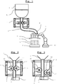
- Fig. 1 a filling system according to the invention is shown schematically.
- the reciprocal hose pump 1 is arranged on a hose 2, which is connected at its inlet end to the bottom of the container 3 and at its outlet end to the filler neck 4 of the filling element 5.
- the filling nozzle 4 opens into the cavity 6 to be filled of a component 7, in particular a hollow chamber brick or hollow brick.
- Per cavity to be filled 6 is advantageously at least one tube 2 with reciprocal hose pump 1 available, the reciprocal peristaltic pumps 1 of the different tubes 2 are operated at different void size with different stroke, or the hoses 2 have a different cross-section. Likewise, it would be possible with several hoses 2 to promote in a cavity 6, or to distribute the funded with a stroke volume of a hose 2 to two or more cavities 6.
- the filling element 5 may have a closure element 8 for closing the filler neck 4 to prevent leakage of foam material between the filling operations.
- a closure element 8 is mounted directly on the filler neck 4, or closes the outlet opening, dripping is prevented. If, however, as known from the prior art on the hose 2, a closure device is present, for example in the form of a device for clamping the tube 2, it comes as already described for dripping by expansion of the foam in the area after the clamping.
- a closure device or closure element 8 are suitable in addition to valves and slides all other known in the prior art devices for selectively opening and closing an outlet opening.
- the components 7 are preferably moved with a transport device, in particular a conveyor belt 9, relative to the filling device.
- the filling element 5 can relative to the transport device or be kept movable to the filling plant, for example, on the arm of an industrial robot 10 or by one or more linear drives in the x, y, and / or z direction.
- the relative movement of the filling element 5 is made possible in that in each case a flexible hose line runs between the reciprocal hose pump 1 and the filler neck 4, preferably in that each hose 2 extends continuously from the container 3 to the filling element 5 or the filler neck 4.
- a less preferred variant would be to provide further lines, for example in the form of pipes or hoses, which extend between the container 3 and the reciprocal hose pump 1 and / or between the reciprocal hose pump 1 and the filling element 5.
- the filling element 5 preferably has a carrier in which the filler neck 4 are fixed or fixable in position according to the position of the cavities 6 of the component 7, in particular block, wherein the position of the filler neck 4 is changeable in the carrier, or the carrier with a carrier is replaceable with other Grestutzenan für assupra.
- the filling element 5 may have at least one switching element, preferably in the form of a three-way valve, or a linear slide plate, to which at least one line coming from the reciprocal hose pump 1, in particular a hose 2, and at least one filler neck 4 are connected.
- an agitator 11 is preferably attached, which keeps the foam to be filled in motion in order to prevent deposition or hardening on the container wall.
- FIGS. 2 and 3 is the reciprocal hose pump 1 shown in detail, in which the hose 2 is guided vertically by the reciprocal hose pump 1.
- the reciprocal hose pump 1 consists of a frame 12 which has a guide for a vertically movable carriage 13.
- the tube 2 is preferably fixed at the upper end of the frame 12 and at the lower end of the frame 12 in its position.
- On the carriage 13 are two rollers 14, 15 opposite each other on both sides of the hose 2 attached.
- the rollers 14, 15 are each mounted on its axis, so that they roll on the hose 2, to keep the stress of the hose 2 low.
- the hose 2 is the reciprocal hose pump 1 shown in the dispensing process, in which the hose 2 is so strongly squeezed by the small distance between the rollers 14, 15 that no or hardly material the hose 2 between the two rollers 14, 15 can happen.
- the rollers 14, 15 Upon downward movement of the carriage 13, the rollers 14, 15 are moved synchronously downwards, whereby the material in the tube 2 is pushed down out of this. Above the rollers 14, 15 material is sucked from the container 3 into the tube 2.
- the way the two rollers 14, 15 cover during application determines the discharge rate per cycle. When the lowest point of the path is reached, as in Fig.
- the cleaning can take place in that cleaning fluid is passed through the hose 2 and / or mechanically cleaned with a hose brush and / or the hose 2 is deformed by the action of force from the outside, for example by tapping with a hammer.
- the filling device shown can be used in foams, the flowability is so low that they would not flow alone through gravity due to the hose 2.
- the outlet of the hose 2 are closed over, for example, a slide.
- the closure element 8 of the respective tube 2 or filling nozzle 4 and the adjustment of the roller 14 mechanically, electrically, pneumatically or hydraulically coupled, so that the moving away of the roller 14 from the tube 2 and the closure with the closure element 8 takes place at the same time.
- the adjusting devices of the roller 14 and the closure element 8 are single-acting hydraulic or pneumatic cylinders, wherein both cylinders can be acted upon by a common control valve with pressure. For example, when pressure is applied, the roller 14 is moved against the hose 2 by the cylinder against a spring force, and the closure element 8 is opened counter to a spring force.
- the orientation of the hose 2 may be arbitrary, for example, horizontal or oblique, a promotion vertically upwards is possible. Less preferably one can not perform the stop as a roller 15, but for example as a surface against which the hose 2, so that it is squeezed between the surface and roller 14. Instead of as in Fig. 3 shown the roller 14 wegzuschwenken from the tube 2, this can also be moved away from the tube 2 translationally. It may also be provided that the roller 15 is not as in FIGS. 2 and 3 is shown, assumes a fixed position, but that both rollers 14, 15 are moved away from the tube 2. The movement of the roller 14 and / or the roller 15 or any other stop towards and / or away from the hose 2 can be effected via a mechanical, electromechanical, magnetic, pneumatic or hydraulic adjusting device.
- a reciprocal hose pump 1 for example, per hose 2, which runs from the container 3 to the filling element 5, a reciprocal hose pump 1 according to FIGS. 2 and 3 available.
- a plurality of tubes 2 can be provided with a reciprocal hose pump 1 according to the invention, wherein the frame 12 per hose 2 an adjustable roller 14 and a stationary roller 15 are provided on the carriage 13, wherein the rollers 14, as shown, may be arranged parallel to each other.
- a roller 14 acts on a plurality of tubes 2, in which case the delivery rate of the four tubes 2 shown is uniform, unless it hoses 2 are used with different sized cross-sectional area.
- a cycle consisting of an up and a down movement of the carriage 13 thus eight hoses 2 could be emptied simultaneously.
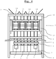
- a reciprocating hose pump 1 according to the invention is shown, which per hose 2 has an adjustable roller 14, wherein the rollers 14 are arranged one after the other in the longitudinal direction.
- the rollers 14 can be brought independently of each other to the respective tube 2, or moved away from it, so that different quantities per tube 2 can be promoted in a cycle by the rollers 14 during the downward movement of the carriage 13 are kept in that position for different lengths, in which they squeeze the tube 2.
- Fig. 6 as a side view of Fig. 4
- a cycle consisting of an up and a down movement of the carriage 13 thus eight hoses 2 simultaneously emptied, the amount of emptying for each hose 2 is individually controllable or regulated.
- the filling plant can be placed in the form of a container 3 and the reciprocal hose pump 1 according to the invention directly above a conveyor belt 9, so that the components 7 directly under the filler 4 and the openings the hoses 2 can be moved so that the foam to be filled is conveyed on a direct vertical path from the container 3 into the components 7.
- the filler neck 4 are shown as shown by a filling element 5. This may be movably supported relative to the frame 12 to allow for accurate positioning over the component 7 or to follow movement of the component 7 on the conveyor belt 9 during the filling process. If the components 7 are moved in exact position and orientation under the filling line and the conveyor belt 9 stops on reaching the desired position, the filler neck 4 may be mounted in a fixed position on the frame 12.
- the filling nozzles 4 can have a common closure element 8, or can be closed individually by a closure element 8 assigned to the respective filler neck 4. If the filling system is to be used to fill different components 7, it can be provided that the filling nozzles 4 can be positioned individually or in groups, or the filling element has 5 valves in order to be able to supply the material flow from a hose 2 to different filler nozzles 4.
- the filler neck 4 can be lowered into the cavities 6 and are moved out of these during the filling process.
- the preferred filling method for cavities 6 with different volumes is based on the Fig. 6 described.
- the component 7 of Fig. 6 has four cavities 6, wherein the two middle cavities 6 are larger than the two outer cavities and, for example, have twice the volume.
- Each cavity 6 is filled with a tube 2, wherein on each tube 2, a roller 14 acts and the rollers 14 are mounted on a common carriage 13. At the upper starting point of the movement of the carriage 13, all rollers 14 are moved up to the stop, so that all hoses 6 are disconnected. The carriage 13 is moved down until the two middle cavities 6 are filled, wherein the two outer rollers 14 are pivoted away from the respective tube 2 as soon as the two outer cavities 6 are full, ie when half the distance has been reached.
- the two middle rollers 14 are moved away from the respective tubes 2 and the carriage 13 is brought back into the upper position.
- the two central rollers 14 squeeze the respective tubes 2 and the two outer rollers 14 are moved up to the respective tubes 2 only when half the distance is reached.
- leading through the reciprocal hose pump 1 hoses 2 can also be attached to different containers 3 and thus can accommodate different media.
- a rotary tube pump 1 according to the invention
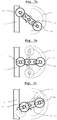
- a hose pump 1 according to the invention is shown in three representations, each with a different orientation of the rotor 16.
- On the rotor 16 for example, two roller 14 are mounted, which are moved upon rotation of the rotor 16 along a circular path.
- the hose 2 can, as in the left part of the Fig.
- roller 14 is pressed by the actuator against a spring force with a defined force to the outside, so that the tube 2 is crushed during movement of the roller 14 along its longitudinal direction between the roller 14 and the stopper with a defined force, as in the Fig. 7a and 7b shown. If the force is removed by the actuator, the roller 14 is moved away by the spring force from the tube 2, so that it is no longer squeezed between the roller 14 and the stop, as it is in Fig.
- Fig. 7c the rotor 16 is shown in dashed lines in that position, which the roller 14 has long been possible to cover in crimped contact with the straight tube 2.
- rotor 16 shown with solid lines the roller 14 is already moved away from the tube 2 before reaching this position, so that a correspondingly lower volume is promoted.
- the tube 2 is shown dotted, in which case the tube 2 is arranged in a circular arc along the orbit of the roller 14, so that the roller 14 is in contact with the tube 2 longer per revolution of the rotor 16.
- a likewise arcuate stop (not shown).
- the hose pump 1 of the invention can Fig. 7a-c So also how an ordinary peristaltic pump 1 are operated when both rollers 14 constantly remain in the outer position, whereby the peristaltic pump 1 promotes quasi-continuous.
- Fig. 7b the rotor 16 shown in dashed lines in the vertical position, with two rollers 14 in the outer position of the tube 2 squeezing position.
- the hose 2 is in this mode of operation, as in a conventional peristaltic pump, at any time by at least one of the rollers 14 clamped.
- the discharge rate can thus be controlled at a constant speed of the rotor 16 over the frequency and the duration of those periods, which cover the rollers 14 by pressing the adjusting device in crimped contact with the tube 2.
- the squeezing effect can be taken at any time from the tube 2, so that when a cavity 6 is completely filled with foam, the squeezing effect can be removed immediately and is only restored to fill the next cavity 6.
- the rotor 16 does not have to be stopped.
- a particularly valuable peristaltic pump 1 according to the invention Fig. 7a-c results when a plurality of rollers 14 and roller pairs are successively mounted along the axis of the rotor 16 on this and each of these rollers 14 and each roller pair acts on its own tube 2 and has its own adjusting device, so that each roller 14 or each Roller pair can be moved independently of the other rollers 14 and roller pairs to the respective tube 2, so that the delivered volume per tube 2 is independent of the other hoses 2 controllable. Since all rolls 14 or pairs of rolls are moved by a common rotor 16, a simple compact device results, for controlled filling or metering with several hoses 2.
- the number of mounted on the rotor 16 rollers 14, which act on a hose 2 does not have to be two as shown, for example, it can be mounted on the rotor 16, for example, only one roller 14.
- three, four or more rollers 14 act on a hose 2, which advantageously evenly, ie each present at the same angle to each other on the rotor 16 and each roller 14 has an adjusting device with which the radial distance from the axis of rotation of the rotor 16 is controllable or changeable. It may be sufficient if an adjusting device is present, which controls the distance of all rollers 14, which act on a hose 2, uniformly or changes.
Description
Die Erfindung betrifft eine Abfüllanlage für das Füllen von mineralischen Dämmstoffschäumen in Hohlräume, insbesondere in Hohlräume von Baustoffen beziehungsweise Bauelementen wie insbesondere Bausteine unter Verwendung einer reziproken Schlauchpumpe und ein erfindungsgemäßes Verfahren zum Betrieb einer erfindungsgemäßen reziproken Schlauchpumpe.The invention relates to a bottling plant for filling mineral insulation foams in cavities, in particular in cavities of building materials or components such as in particular building blocks using a reciprocal hose pump and an inventive method for operating a reciprocal peristaltic pump according to the invention.
Reziproke Pumpen (oder oszillierende Pumpen) sind in Form von Kolbenpumpen oder Membranpumpen bekannt, welche im ersten Takt das Fördermedium über ein Einlassventil ansaugen und im zweiten Takt das Fördermedium über das Auslassventil herausdrücken. Reziprok bedeutet in diesem Zusammenhang, dass die Bewegung des Kolbens bzw. der Membran im ersten Takt und im zweiten Takt in entgegengesetzter Richtung erfolgt. Gewöhnliche Schlauchpumpen stellen keine reziproken Pumpen dar, da diese kontinuierlich fördern, indem zumindest zwei Walzen, welche an einem Rotor diagonal gegenüberliegend angebracht sind, über einen kreisbogenförmigen Abschnitt des Schlauches bewegt werden, sodass der Schlauch ständig durch zumindest eine Walze gequetscht ist. Weiters sind lineare Schlauchpumpen bekannt, bei welchen das Fördermedium kontinuierlich mit einer Nockenwelle bewegt wird. Die reziproke Schlauchpumpe der gegenständlichen Abfüllanlage ist, wie der Name sagt eine Schlauchpumpe mit reziprokem Wirkprinzip und weist daher einen Ausbringtakt und einen Leertakt ohne Ausbringung auf.Reciprocal pumps (or oscillating pumps) are known in the form of piston pumps or diaphragm pumps, which suck in the first cycle the fluid through an inlet valve and push out the fluid through the outlet valve in the second cycle. In this context, reciprocal means that the movement of the piston or the membrane takes place in the opposite direction in the first cycle and in the second cycle. Ordinary peristaltic pumps are not reciprocal pumps because they continuously convey by moving at least two rollers mounted diagonally opposite each other on a rotor over an arcuate section of the hose so that the hose is constantly squeezed by at least one roller. Furthermore, linear peristaltic pumps are known in which the fluid is moved continuously with a camshaft. The reciprocal peristaltic pump of the subject bottling plant is, as the name implies a peristaltic pump with reciprocal action principle and therefore has a Ausbringtakt and a blank cycle without application.
Die
Die
Die
Die
Die
Die
Die
Nach dem Stand der Technik sind Füllvorrichtungen zum Befüllen von Hohlräumen mit Schäumen bekannt, wobei nach dem Stand der Technik zumeist Kolbendosierer oder Kolbenpumpen für diesen Zweck Anwendung finden. Daneben wurden auch Schneckenförderer eingesetzt. Jeder Kolbendosierer bzw. jede Kolbenpumpen weist einen Behälter zur Aufnahme von Schaummaterial sowie ein Füllelement zum Einführen des Schaumaterials in einen Hohlraum, einen Kolbenzylinder zum Fördern des Schaummaterials vom Behälter zum Füllelement und ein Ventilelement, mit dem wahlweise eine Kommunikation zwischen dem Behälter und dem Kolbenzylinder sowie dem Kolbenzylinder und dem Füllelement herstellbar ist, auf.According to the state of the art, filling devices for filling cavities with foams are known, and in the prior art, piston dispensers or piston pumps are usually used for this purpose. In addition, screw conveyors were used. Each piston feeder or each piston pump has a container for receiving foam material and a filling element for introducing the foam material into a cavity, a piston cylinder for conveying the foam material from the container to the filling element and a valve element with which either a communication between the container and the piston cylinder and the piston cylinder and the filling element can be produced on.
Die
Die
In der österreichischen Gebrauchsmusteranmeldung
Besonders bei rasch aushärtenden Schäumen, bzw. Materialien die sich schnell am Inneren von Leitungen und Schläuchen anlegen, haben alle genannten Vorrichtungen bzw. Pumpen den Nachteil, dass diese nur mit einigem Aufwand von Anlagerungen befreit werden können, wobei die Schlauchpumpe den Vorteil hat, dass die mechanischen beweglichen Komponenten der Schlauchpumpe nicht mit dem zu fördernden Schaum in Berührung kommen.Especially with rapidly curing foams, or materials that build up quickly on the inside of pipes and hoses, all mentioned devices or pumps have the disadvantage that they can be freed from deposits only with some effort, the hose pump has the advantage that the mechanical moving components of the peristaltic pump do not come into contact with the foam to be delivered.
Für besonders empfindliche Schäume, also Schäume mit sehr hohem Luftanteil bzw. Gasanteil hat sich herausgestellt, dass deren Struktur maßgeblich von der Abfüllung beeinflusst wird, wobei im schlimmsten Fall die Schaumstruktur zusammenbricht und dieser seinen Zweck nach Abfüllung somit nicht mehr erfüllen kann. Wann ein Schaum zusammenbricht hängt von mehreren Faktoren ab, wobei mechanische Belastungen insbesondere dynamische Lasten eine maßgebliche Rolle zu spielen scheinen. Eine sich ändernde Beanspruchung des Schaumes, beispielsweise aufgrund einer geänderten Pumpendrehzahl, kann somit dazu führen, dass sich die Schaumeigenschaften und die Stabilität des Schaumes ändern können, was den Abfüllprozess schwer zu kontrollieren macht. Eine Einstellung der pro Zeiteinheit geförderten Menge des Schaumes durch Drehzahländerung ist somit nachteilig, was somit die Verwendung einer kontinuierlich fördernden Pumpe, wie einer herkömmlichen Schlauchpumpe mit Nachteilen behaftet. Beim Fördern von Mineralschäumen mit einer normalen Rotationsschlauchpumpe ist insbesondere nachteilig, dass die Rotationsschlauchpumpe nach jedem Befüllen einer Kammer gestoppt wird und dadurch der Mineralschaum, welcher sich im Schlauchbereich von der Schlauchpumpe bis zur Austrittsöffnung befindet, noch eine leichte Druckbeaufschlagung erfährt. Dadurch expandieren die Gas- bzw. Luftporen langsam und Schaum tropft über einen längeren Zeitraum nach, was zu Materialverlusten und Verunreinigung führt. Je länger die Leitung bzw. der Schlauch zwischen der Pumpe und der Austrittsöffnung ist, umso stärker ist dieser Effekt. Dieser Effekt würde auch bei allen genannten reziproken Schlauchpumpen auftreten, wenn mit diesen ein Schaum gepumpt würde, da die genannten reziproken Schlauchpumpen mit Quetschrollen oder Elementen wechselwirken, welche unterhalb der reziproken Schlauchpumpe bei Beendigung des Ausbringhubes den Schlauch abquetschen. Folglich würde der Schaum hinter der abgequetschten Stelle eine Expansion, aufgrund der komprimierten Gas- bzw. Luftblasen, erfahren und nachtropfen.For particularly sensitive foams, ie foams with a very high proportion of air or gas content has been found that their structure is significantly influenced by the filling, which collapses in the worst case, the foam structure and thus its purpose after filling can no longer meet. When a foam collapses depends on several factors, with mechanical loads, especially dynamic loads, playing a significant role. A changing load of the foam, for example due to a changed pump speed, can thus lead to the Foam properties and foam stability, making the filling process difficult to control. An adjustment of the per unit time promoted amount of foam by speed change is thus disadvantageous, thus affecting the use of a continuously pumping pump, such as a conventional peristaltic pump with disadvantages. When pumping mineral foams with a normal rotary hose pump is particularly disadvantageous that the rotary tube pump is stopped after each filling a chamber and thereby the mineral foam, which is located in the hose area of the peristaltic pump to the outlet opening, still undergoes a slight pressurization. As a result, the gas or air pores expand slowly and foam drips over a longer period of time, resulting in material losses and contamination. The longer the line or hose between the pump and the outlet opening, the stronger this effect. This effect would also occur in all reciprocal peristaltic pumps mentioned, if with these a foam would be pumped, since said reciprocating peristaltic pumps interact with squeezing rollers or elements which squeeze the tube below the reciprocal hose pump at the end of the Ausbringhubes. Consequently, the foam behind the pinched point would experience expansion and dripping due to the compressed gas or air bubbles.
Aufgabe der gegenständlichen Erfindung ist es, einen Fördermechanismus für eine Abfüllanlage für empfindliche mineralische Dämmstoffschäume bereit zu stellen, der das Anlagern von Material verhindert, bzw. eine rasche Reinigung von bereits angelagertem Material erlaubt, wobei die Fördermenge flexibel einstellbar sein, ohne die Belastung (insbesondere die dynamische Last), welche auf das zu fördernde Material wirkt, zu verändern. Eine Änderung der Belastung tritt immer dann auf, wenn die Änderung der Fördermenge über Geschwindigkeitsänderung bzw. Drehzahländerung der Pumpe erreicht wird.Object of the subject invention is to provide a delivery mechanism for a bottling plant for sensitive mineral insulation foams, which prevents the attachment of material, or allows rapid cleaning of already attached material, the flow rate can be flexibly adjusted without the burden (in particular the dynamic load), which acts on the material to be conveyed change. A change in the load always occurs when the change in the flow rate is achieved by changing the speed or changing the speed of the pump.
Erfindungsgemäß wird zur Lösung der Aufgabe vorgeschlagen, zur Abfüllung von empfindlichen mineralischen Dämmstoffschäumen eine reziproke Schlauchpumpe gemäß Anspruch 1 zu verwenden.According to the invention is proposed to solve the problem, to use a reciprocal peristaltic pump according to
Durch die reziproke Ausführung wird der Mineralschaum durch das Walzensystem nach unten gedrückt und beim Abheben der Walzen entsteht sofort eine Rücksaugwirkung auf den Mineralschaum, welcher sich im Schlauchbereich von der Schlauchpumpe bis zur Austrittsöffnung befindet. Das Nachtropfen entfällt und unnötiger Materialverlust wird somit verhindert.Due to the reciprocal design of the mineral foam is pressed down through the roller system and when lifting the rollers immediately creates a suction effect on the mineral foam, which is located in the hose area of the peristaltic pump to the outlet opening. The dripping is eliminated and unnecessary material loss is thus prevented.
Das Steuern des Fördervolumens der reziproken Schlauchpumpe erfolgt gemäß dem erfindungsgemäßen Verfahren der Ansprüche 10 bis 15, da sich bei diesem die auf den mineralischen Dämmstoffschaum wirkende Belastung bei Änderung des Fördervolumens nicht ändert. Reziproke Schlauchpumpen sind zwar an sich bekannt, deren Verwendung zur Abfüllung von Schäumen im Allgemeinen und empfindlichen mineralischen Dämmstoffschäumen im Speziellen jedoch nicht. Bislang wurden reziproke Schlauchpumpen lediglich zum Abfüllen von aus hygienischen (z.B. Lebensmittel) oder umweltschutzgründen (z.B. Batterieflüssigkeit) heiklen Produkten verwendet, um eine Kontamination des Produkts oder eine Kontamination der Anlage durch das Produkt zu verhindern. Für andere allgemeine Zwecke, also zur Förderung von unbedenklichen Produkten, werden aufgrund des einfacheren Aufbaus oder der an sich vorteilhaften kontinuierlichen Förderung andere Pumpenprinzipien eingesetzt. Beispielsweise reziproke Kolbenpumpen zur Füllung von Bausteinen, aufgrund des einfacheren Aufbaus. Rotatorische Schlauchpumpen zur kontinuierlichen Förderung von Beton, aufgrund der kontinuierlichen und somit höheren Förderleistung (kein Leerhub).The control of the delivery volume of the reciprocal hose pump is carried out according to the inventive method of
Die gegenständliche Erfindung basiert somit nicht auf der Verwendung der reziproken Schlauchpumpe aufgrund des bekannten Anwendungszweckes des Ausschlusses von Kontamination, da mineralische Dämmstoffschäume völlig unbedenklich sind, sondern besteht in der Verwendung der reziproken Schlauchpumpe aufgrund der sanften Förderung des empfindlichen Schaumes, insbesondere der Möglichkeit der Einstellung der geförderten Menge pro Zeiteinheit unabhängig von einer Geschwindigkeitsänderung der Pumpe und somit Belastungsänderung des Schaumes.The subject invention is thus not based on the use of the reciprocal peristaltic pump due to the known application of the exclusion of contamination, as mineral insulation foams are completely harmless, but consists in the use of the reciprocal hose pump due to the gentle promotion of the sensitive foam, in particular the Possibility of setting the delivered amount per unit time regardless of a change in the speed of the pump and thus load change of the foam.
Die gegenständliche Erfindung ist vorteilhaft, da sie die Verwendung einer an sich für den allgemeinen Anwendungszweck nachteiligen Pumpenart, welche in einem anderen Gebiet der Technik (Förderung von unaufgeschäumten, somit nicht-komprimierbaren hygienisch oder gesundheitlich heiklen Medien) dennoch notwendig ist, zur sanften Förderung von gesundheitlich unbedenklichen aber komprimierbaren und empfindlichen mineralischen Dämmstoffschäumen vorschlägt.The subject invention is advantageous because it still requires the use of a per se for the general purpose pump type, which in any other field of technology (promotion of unfoamed, thus non-compressible hygienic or health sensitive media), for the gentle promotion of healthy but compressible and sensitive mineral insulation foams.
Erfindungsgemäß wird als Verwendung der reziproken Schlauchpumpe zur Abfüllung von empfindlichen mineralischen Dämmstoffschäumen eine Abfüllanlage vorgeschlagen, umfassend einen Behälter, welcher zumindest teilweise mit dem zu verfüllenden Schaummaterial gefüllt ist und zumindest eine Öffnung aufweist, von welcher eine Leitung zu einem Füllelement führt, derart auszugestalten, dass jede zwischen einer Öffnung des Behälters und dem Füllelement verlaufende Leitung zumindest abschnittsweise als Schlauch ausgeführt ist und an diesem Schlauchabschnitt eine reziproke Schlauchpumpe aufweist, bei welcher ein den Schlauch quetschendes Element entlang der Längsrichtung des Schlauches bewegt wird, welches dann in entgegengesetzter Richtung zurückbewegt wird, ohne den Schlauch zu quetschen. Das den Schlauch quetschende Element ist dazu durch eine Stellvorrichtung zum Schlauch hin bewegbar, um diesen zu quetschen und vom Schlauch wegbewegbar um den Schlauch nicht zu quetschen, wobei das geförderte Volumen bei einer Bewegung der Walze vom Ausgangspunkt bis zum Endpunkt entlang der Längsrichtung des Schlauches gesteuert wird, indem durch Ansteuerung der Stellvorrichtung der Schlauch nur in einem Teilbereich dieser Bewegung gequetscht wird. Sobald das den Schlauch quetschende Element durch seine Stellvorrichtung vom Schlauch wegbewegt wird, wird die Druckbeaufschlagung vom Schaum genommen und es kommt zu keiner langsamen Expansion des Schaums, welche ein langes Nachtropfen bedeutet. Durch den vom expandierenden Schlauch ausgeübten Sog wird der Schaum meist sogar etwas zurück in Richtung der reziproken Schlauchpumpe bewegt. Bevorzugt weist die erfindungsgemäße Vorrichtung kein Verschlusselement, bzw. keine zusätzliche Vorrichtung zum Quetschen des Schlauches hinter den Quetschrollen der reziproken Schlauchpumpe auf, sodass der Weg vom Einlass der reziproken Schlauchpumpe bis zur Auslassöffnung des Schaumes in den zu füllenden Hohlkörper frei ist, sobald das den Schlauch quetschende, reziprok bewegte Element vom Schlauch wegbewegt wurde.According to the invention, a bottling plant is proposed as the use of the reciprocal peristaltic pump for filling sensitive mineral foam foams, comprising a container which is at least partially filled with the foam material to be filled and has at least one opening, from which a conduit leads to a filling element, such that each extending between an opening of the container and the filling element line is at least partially designed as a hose and on this hose section has a reciprocal hose pump, in which a hose pinching element along the longitudinal direction of the hose is moved, which is then moved back in the opposite direction, without to squeeze the hose. The squeezing the hose member is to be moved by an actuator to the hose to squeeze it and wegbewegbar from the hose to not squeeze the hose, wherein the funded volume controlled during movement of the roller from the starting point to the end along the longitudinal direction of the hose is squeezed by driving the adjusting device of the hose only in a portion of this movement. As soon as the element crushing the tube is moved away from the tube by its adjusting device, the pressure is taken from the foam and there is no slow expansion of the foam, which means a long dripping. By the of As a result of the expansion of the suction hose, the foam is usually even moved backwards in the direction of the reciprocal peristaltic pump. Preferably, the device according to the invention has no closure element, or no additional device for squeezing the tube behind the squeezing rollers of the reciprocal hose pump, so that the path from the inlet of the reciprocal hose pump to the outlet opening of the foam in the hollow body to be filled is free, as soon as the hose squeezing, reciprocal moving element was moved away from the hose.
Gemäß der bekannten Funktionsweise der reziproken Schlauchpumpe kann das geförderte Volumen pro Bewegungszyklus der reziproken Schlauchpumpe über die Strecke gesteuert oder geregelt werden, welche das den Schlauch quetschende Element in quetschendem Kontakt mit dem Schlauch entlang der Längsrichtung des Schlauches zurücklegt. Bekannte reziproke Schlauchpumpen weisen dazu meist einen in Längsrichtung des Schlauches beweglichen Schlitten auf, an welchem als quetschendes Element eine drehbare Walze befestigt ist, wobei der Schlitten zyklisch entlang des Schlauches in entgegengesetzten Richtungen zwischen zwei Endpunkten bewegbar ist, wobei der Schlauch bei Bewegung des Schlittens in die erste Richtung bis zum unteren Endpunkt zwischen der Walze und einem Anschlag gequetscht wird und bei Bewegung in die zweiten Richtung nicht zwischen der Walze und dem Anschlag gequetscht wird. Erfindungsgemäß wird eine demgegenüber neue Steuerung des geförderten Volumens pro Bewegungszyklus der reziproken Schlauchpumpe vorgeschlagen, bei welcher der Hub der Vorrichtung bzw. des Schlittens nicht geändert wird, bzw. nicht verstellt wird. Die erfindungsgemäße reziproke Schlauchpumpe weist dazu auch einen in Längsrichtung des Schlauches beweglichen Schlitten oder ein sonstiges Bauteil auf, an welchem als quetschendes Element eine drehbare Walze befestigt ist, wobei der Schlitten zyklisch entlang des Schlauches in entgegengesetzten Richtungen zwischen zwei Endpunkten bewegbar ist. Zum Unterschied ist aber vorgesehen, dass der Schlauch bei Bewegung des Schlittens in der ersten Richtung bis zum unteren Endpunkt in einem steuerbaren Teilbereich dieser Bewegung zwischen der Walze und einem Anschlag gequetscht wird und bei Bewegung in die zweite Richtung nicht zwischen der Walze und dem Anschlag gequetscht wird.According to the known operation of the reciprocal hose pump, the delivered volume per cycle of movement of the reciprocal hose pump can be controlled or regulated over the distance which traverses the hose squeezing element in crushing contact with the hose along the longitudinal direction of the hose. Known reciprocal peristaltic pumps have for this purpose usually a movable in the longitudinal direction of the tube carriage on which a rotatable roller is attached as crimping element, wherein the carriage is cyclically movable along the tube in opposite directions between two end points, wherein the tube upon movement of the carriage in the first direction is squeezed to the lower end point between the roller and a stop and is not squeezed between the roller and the stop when moving in the second direction. In contrast, according to the invention, a new control of the delivered volume per cycle of movement of the reciprocal peristaltic pump is proposed, in which the stroke of the device or of the carriage is not changed or not adjusted. The reciprocating peristaltic pump according to the invention also has a slide movable in the longitudinal direction of the tube or another component to which a rotatable roller is attached as a squeezing element, wherein the slide is cyclically movable along the tube in opposite directions between two end points. By contrast, it is provided that the hose when moving the carriage in the first direction is squeezed to the lower end point in a controllable portion of this movement between the roller and a stop and is not squeezed between the roller and the stop when moving in the second direction.
Der Hub der Vorrichtung bzw. des Schlittens ist dadurch konstant, wobei die Walze eine zusätzliche Stellvorrichtung aufweist, mit welcher diese vom Schlauch wegbewegt werden kann. Dadurch, dass der Schlitten nur zwischen zwei Endpunkten hin- und herbewegt werden muss, gestaltet sich dessen Antrieb entsprechend einfach und kann beispielsweise als Hydraulik- oder Pneumatikzylinder ausgeführt sein. Die zusätzliche Stellvorrichtung kann ebenfalls einfach gehalten sein, da durch diese die Walze lediglich in Richtung des Schlauches hin- und von diesem wegbewegt werden muss. Das Steuern des geförderten Volumens erfolgt ausschließlich durch zeitliche Ansteuerung der zusätzlichen Stellvorrichtung, indem diese den quetschenden Kontakt der Walze mit dem Schlauch nur über einen Teilbereich der Abwärtsbewegung des Schlittens aufrecht hält.The stroke of the device or the carriage is thereby constant, wherein the roller has an additional adjusting device, with which it can be moved away from the hose. Due to the fact that the carriage only has to be moved back and forth between two end points, its drive is correspondingly simple and can be designed, for example, as a hydraulic or pneumatic cylinder. The additional adjusting device can also be kept simple, since through this the roller only has to be moved back and forth in the direction of the hose. The controlled volume is controlled exclusively by time control of the additional adjusting device by maintaining the squeezing contact of the roller with the hose only over a portion of the downward movement of the carriage upright.
Besonders wertvoll ist diese neue erfindungsgemäße Vorrichtung dann, wenn von dem einen Schlitten mehrere Walzen zyklisch auf- und abbewegt werden, welche jeweils auf einen eigenen Schlauch wirken und jeweils eine eigene Stellvorrichtung aufweisen, mit welcher der quetschende Kontakt der Walze mit dem Schlauch wahlweise herstellbar ist. Dadurch kann mit nur einem parallel zu den Schläuchen bewegten Schlitten das geförderte Volumen für jeden Schlauch individuell gesteuert werden.Particularly valuable is this new device according to the invention, when several rollers are cyclically moved up and down by the one carriage, each acting on its own hose and each have their own adjusting device, with which the squeezing contact of the roller with the hose is selectively produced , As a result, with only one carriage moved parallel to the hoses, the delivered volume for each hose can be individually controlled.
Bevorzugt ist im Schaumbehälter ein Rührelement angebracht, welches den Schaum in Bewegung hält und eine gleichmäßige Verteilung des Schaums am Boden des Behälters gewährleistet. Besonders bevorzugt wird die Füllmenge bzw. der Füllstand des Schaumes in den Hohlräumen des zu füllenden Bauelements erfasst und der Hub der reziproken Schlauchpumpe in Abhängigkeit davon geregelt. Die Erfassung der Füllmenge bzw. des Füllstands kann dabei bereits laufend während der Füllung oder nach beendeter Füllung erfolgen.Preferably, a stirring element is mounted in the foam container, which keeps the foam in motion and ensures a uniform distribution of the foam at the bottom of the container. Particularly preferably, the filling quantity or the filling level of the foam is detected in the cavities of the component to be filled and the stroke of the reciprocal hose pump is regulated in dependence thereon. The detection of the capacity or the level can already be done during the filling or after completion of filling.
Bevorzugt wird die Füllmenge bzw. der Füllstand bei Baustoffen mit mehreren Hohlräumen für jeden Hohlraum einzeln erfasst und die dem jeweiligen Hohlraum zugeordnete reziproke Schlauchpumpe in Abhängigkeit davon geregelt.Preferably, the filling quantity or the filling level is individually detected for building materials with a plurality of cavities for each cavity, and the reciprocal peristaltic pump associated with the respective cavity is regulated in dependence thereon.
Sollte der Schaum nach Abfüllen im Hohlraum eine Expansion erfahren, so wird die Füllmenge, bzw. der Füllstand bevorzugt nach beendeter Expansion erfasst, sodass exakt die benötigte Menge Schaum eingebracht werden kann, was zu einer minimalen Verbrauch des Schaummaterials führt.If the foam undergoes expansion after filling in the cavity, then the filling quantity or the level is preferably detected after completion of expansion, so that exactly the required amount of foam can be introduced, which leads to a minimum consumption of the foam material.
Besonders bevorzugt liegen die Baustoffe in Form von vorgefertigten Elementen wie Bausteinen, insbesondere Hohlziegeln vor, welche auf einem Fließband zur gegenständlichen Anlage transportiert werden.Particularly preferred are the building materials in the form of prefabricated elements such as building blocks, in particular hollow bricks, which are transported on an assembly line to representational plant.
Besonders bevorzugt ist die Fülleinheit, welche die Auslassenden der erfindungsgemäßen Anlage aufnimmt, am Arm eines Industrieroboters befestigt, wobei besonders bevorzugt die Fülleinheit während des Abfüllvorgangs mit dem Förderband mitbewegt wird, sodass die Baustoffe am Förderband mit einer konstanten Geschwindigkeit transportiert werden können. Dadurch werden Beschleunigungsvorgänge des Fließbands vermieden, was insbesondere einen geringeren Energieverbrauch zur Folge hat. Besonders bevorzugt wird die Fülleinheit, welche zumindest ein Auslassende der erfindungsgemäßen Anlage aufnimmt, von einem Roboter mit Linearantrieben in x-, y-, und bevorzugt z-Richtung positioniert, wobei die Hohlräume eines ruhenden oder bewegten Baustoffs nacheinander in der xy-Ebene angesteuert werden können und bevorzugt in der z-Richtung das zumindest eine Auslassende in den jeweils zu füllenden Hohlraum abgesenkt und während der Füllung aus diesem herausbewegt werden kann. Die reziproke Schlauchpumpe ist für diesen Anwendungsfall besonders wertvoll, da sich zwischen Pumpe und Auslassende zwangsläufig eine Schlauchleitung befinden muss, sodass das Auslassende relativ zur Schlauchpumpe zwischen den Hohlräumen verfahren werden kann. Durch die reziproke Schlauchpumpe wird Nachtropfen auch ohne zusätzliches Verschlusselement verhindert.Particularly preferably, the filling unit, which receives the outlet ends of the system according to the invention, attached to the arm of an industrial robot, wherein particularly preferably the filling unit is moved during the filling process with the conveyor belt, so that the building materials can be transported on the conveyor belt at a constant speed. As a result, acceleration processes of the assembly line are avoided, which in particular results in lower energy consumption. Particularly preferably, the filling unit, which accommodates at least one outlet end of the system according to the invention, is positioned by a robot with linear drives in the x, y, and preferably z direction, wherein the cavities of a stationary or moving building material are controlled successively in the xy plane can and preferably in the z-direction, the at least one outlet end lowered into each cavity to be filled and can be moved out during the filling of this. The reciprocal peristaltic pump is particularly valuable for this application because there must necessarily be a hose between the pump and the outlet end, so that the outlet end can be moved relative to the peristaltic pump between the cavities. The reciprocal hose pump prevents dripping without an additional closing element.
Besonders bevorzugt wird die Lage der Baustoffe am Förderband oder die Lage der Hohlräume im Baustoff sensorisch erfasst, sodass der Roboter diese zielgenau ansteuern kann.Particularly preferably, the position of the building materials on the conveyor belt or the position of the cavities in the building material is detected by sensors, so that the robot can control these accurately.
Die erfindungsgemäße Abfüllanlage kann gegenüber dem Stand der Technik besonders vorteilhaft zum Abfüllen von schnell aushärtenden mineralischen Dämmstoffschäumen mit einem hohen Porenanteil von zumindest 50 %, insbesondere zumindest 70 % verwendet werden. Bevorzugt weist der mineralische Dämmstoffschaum eine Zementmatrix auf und ist selbstaushärtend (d.h. härtet ohne Autoklavierung aus).The bottling plant according to the invention can be used particularly advantageously for filling rapidly hardening mineral insulation foams having a high pore content of at least 50%, in particular at least 70%, compared to the prior art. Preferably, the mineral insulation foam has a cementitious matrix and is self-curing (i.e., cures without autoclaving).
Die Erfindung wird an Hand von Zeichnungen veranschaulicht:
- Fig. 1:
- zeigt eine schematische Darstellung einer beispielhaften erfindungsgemäßen Abfüllanlage mit einer aus anderen technischen Bereichen bekannten reziproken Schlauchpumpe in Ansicht von der Seite.
- Fig. 2:
- zeigt schematisch eine beispielhafte aus anderen technischen Bereichen bekannte reziproke Schlauchpumpe bei Bewegung des Schlittens in einer ersten Richtung.
- Fig. 3:
- zeigt schematisch eine beispielhafte aus anderen technischen Bereichen bekannte reziproke Schlauchpumpe bei Bewegung des Schlittens in einer zweiten Richtung.
- Fig. 4:
- zeigt schematisch eine beispielhafte erfindungsgemäße reziproke Schlauchpumpe, welche je eine Pumpe für zumindest zwei Schläuche ausbildet.
- Fig. 5:
- zeigt schematisch eine beispielhafte erfindungsgemäße reziproke Schlauchpumpe, welche als Pumpe für mehrere Schläuche ausgebildet ist.
- Fig. 6:
- zeigt schematisch eine beispielhafte erfindungsgemäße reziproke Schlauchpumpe, welche je eine Pumpe für je einen von mehreren Schläuchen ausbildet.
- Fig. 7:
- Die
Fig. 7a-c zeigen schematisch eine erfindungsgemäße Schlauchpumpe mit an einem Rotor radial verstellbar befestigten Walzen, in drei verschiedenen Stellungen des Rotors bzw. der Walzen.
- Fig. 1:
- shows a schematic representation of an exemplary filling plant according to the invention with a reciprocal peristaltic pump known from other technical fields in view from the side.
- Fig. 2:
- schematically shows an exemplary reciprocating peristaltic pump known from other technical fields with movement of the carriage in a first direction.
- 3:
- schematically shows an exemplary reciprocating peristaltic pump known from other technical fields when moving the carriage in a second direction.
- 4:
- schematically shows an exemplary reciprocal peristaltic pump according to the invention, which each forms a pump for at least two tubes.
- Fig. 5:
- schematically shows an exemplary reciprocal peristaltic pump according to the invention, which is designed as a pump for a plurality of tubes.
- Fig. 6:
- schematically shows an exemplary reciprocating peristaltic pump according to the invention, which each forms a pump for each one of a plurality of tubes.
- Fig. 7:
- The
Fig. 7a-c show schematically a hose pump according to the invention with radially adjustable on a rotor fixed rollers, in three different positions of the rotor or the rollers.
In
Wie in
Pro zu füllenden Hohlraum 6 ist vorteilhaft zumindest ein Schlauch 2 mit reziproker Schlauchpumpe 1 vorhanden, wobei die reziproken Schlauchpumpen 1 der unterschiedlichen Schläuche 2 bei unterschiedlicher Hohlraumgröße mit unterschiedlichem Hub betrieben werden, oder die Schläuche 2 einen unterschiedlichen Querschnitt aufweisen. Ebenso wäre es möglich mit mehreren Schläuchen 2 in einen Hohlraum 6 zu fördern, oder das mit einem Hub geförderte Volumen eines Schlauches 2 auf zwei oder mehr Hohlräume 6 zu verteilen.Per cavity to be filled 6 is advantageously at least one
Das Füllelement 5 kann über ein Verschlusselement 8 zum Verschließen der Füllstutzen 4 verfügen, um Auslaufen von Schaummaterial zwischen den Füllvorgängen zu verhindern. Indem das Verschlusselement 8 direkt am Füllstutzen 4 angebracht ist, bzw. dessen Austrittsöffnung verschließt, wird Nachtropfen verhindert. Wenn hingegen wie nach dem Stand der Technik bekannt am Schlauch 2, eine Verschlussvorrichtung vorhanden ist, beispielsweise in Form einer Vorrichtung zum Abklemmen des Schlauchs 2, kommt es wie bereits beschrieben zum Nachtropfen durch Expansion des Schaumes im Bereich nach der Abklemmung. Als Verschlussvorrichtung bzw. Verschlusselement 8 eignen sich neben Ventilen und Schiebern alle anderen nach dem Stand der Technik bekannten Vorrichtungen zum wahlweisen Öffnen und Schließen einer Austrittsöffnung.The filling
Die Bauelemente 7 werden bevorzugt mit einer Transportvorrichtung, insbesondere einem Förderband 9, relativ zur Abfüllvorrichtung bewegt. Das Füllelement 5 kann relativ zur Transportvorrichtung bzw. zur Abfüllanlage beweglich gehalten sein, beispielsweise am Arm eines Industrieroboters 10 oder durch einen oder mehrere Linearantriebe in x-, y-, und/oder z-Richtung. Die Relativbewegung des Füllelements 5 wird dadurch ermöglicht, dass zwischen der reziproken Schlauchpumpe 1 und den Füllstutzen 4 jeweils eine flexible Schlauchleitung verläuft, bevorzugt indem sich jeder Schlauch 2 durchgehend vom Behälter 3 bis zum Füllelement 5 bzw. den Füllstutzen 4 erstreckt. Eine weniger bevorzugte Variante wäre weitere Leitungen beispielsweise in Form von Rohren oder Schläuchen vorzusehen, welche sich zwischen dem Behälter 3 und der reziproken Schlauchpumpe 1 und/oder zwischen der reziproken Schlauchpumpe 1 und dem Füllelement 5 erstrecken.The
Das Füllelement 5 weist bevorzugt einen Träger auf, in welchem die Füllstutzen 4 in ihrer Lage entsprechend der Lage der Hohlräume 6 des Bauelements 7 insbesondere Bausteins fixiert oder fixierbar sind, wobei die Position der Füllstutzen 4 im Träger veränderbar ist, oder der Träger mit einem Träger mit anderer Füllstutzenanordnung austauschbar ist und die Schläuche 2 mit Schnellverschlüssen an den Füllstutzen 4 befestigt sind. Weiters kann das Füllelement 5 zumindest ein Umschaltelement aufweisen, vorzugsweise in Form eines Dreiwegeventils, oder einer linearen Schieberplatte, an welchem zumindest eine von der reziproken Schlauchpumpe 1 kommenden Leitung, insbesondere ein Schlauch 2, und zumindest ein Füllstutzen 4 angeschlossen sind.The filling
Im Behälter 3 ist bevorzugt ein Rührwerk 11 angebracht, welches den abzufüllenden Schaum in Bewegung hält, um ein Ablagern bzw. Aushärten an der Behälterwand zu verhindern.In the
In
Um ein unkontrolliertes Entweichen von Schaum bei Aufwärtsbewegung der Walzen 14, 15 zu verhindern, kann der Auslass des Schlauches 2 über beispielsweise einen Schieber verschlossen werden. Vorteilhaft sind das Verschlusselement 8 des jeweiligen Schlauches 2 bzw. Füllstutzens 4 und die Verstellvorrichtung der Walze 14 mechanisch, elektrisch, pneumatisch oder hydraulisch gekoppelt, sodass das Wegbewegen der Walze 14 vom Schlauch 2 und das Schließen mit dem Verschlusselement 8 zeitgleich erfolgt. Beispielsweise sind die Verstellvorrichtungen der Walze 14 und des Verschlusselements 8 einfachwirkende hydraulische oder pneumatische Zylinder, wobei beide Zylinder über ein gemeinsames Steuerventil mit Druck beaufschlagbar sind. Beispielsweise wird bei Druckbeaufschlagung die Walze 14 durch den Zylinder entgegen einer Federkraft an den Schlauch 2 heranbewegt und das Verschlusselement 8 entgegen einer Federkraft geöffnet.In order to prevent an uncontrolled escape of foam during upward movement of the
Als Verallgemeinerungen zur in
Beispielsweise ist pro Schlauch 2, welcher vom Behälter 3 zum Füllelement 5 verläuft, eine reziproke Schlauchpumpe 1 gemäß
Wie in
Wie in
In
Vorteilhaft können so erfindungsgemäße reziproke Schlauchpumpen 1 realisiert werden, welche mit nur einem Rahmen 12, beziehungsweise einer vertikalen Führung und einem beweglichen Schlitten 13 eine nahezu beliebige Anzahl von Schläuchen 2 entleeren können. Dadurch ergibt sich eine kompakte Bauweise, sowie eine kostengünstige, einfach zu reinigende Anlage.Advantageously reciprocal
Wie in
Vorteilhaft kann vorgesehen sein, dass die Füllstutzen 4 in die Hohlräume 6 abgesenkt werden können und während des Füllvorgangs aus diesen herausbewegt werden.Advantageously, it can be provided that the
Das erfindungsgemäße Verfahren zum Abfüllen von Schaummaterial mit der reziproken Schlauchpumpe 1 umfasst folgende Schritte:
- zumindest teilweises Füllen des
Behälters 3 mit Schaum, welcher bevorzugt kontinuierlich von einem Schaummischer inden Behälter 3 gefördert wird, sodass die Öffnungen an denen dieSchläuche 2 angeschlossen sind mit Schaum bedeckt sind, um ein Ansaugen von Luft zu verhindern. - Quetschen jedes Schlauches 2 zwischen einer drehbaren Walze 14 und einem drehbaren Anschlag am Ausgangspunkt der Bewegung der
Walze 14. - Bewegung der drehbaren Walze 14 in quetschendem Kontakt
mit jedem Schlauch 2 in Richtung des Auslassendes des Schlauches 2, um Schaumaus dem Behälter 3 inden Schlauch 2 zu saugen und bei bereits gefülltemSchlauch 2 Material aus dem Auslassende des Schlauches 2 zu quetschen.
- Wenn das benötigte Füllvolumen erreicht ist: Wegnahme der Quetschwirkung, indem die drehbare Walze 14 oder der drehbare Anschlag vom jeweiligen
Schlauch 2 wegbewegt wird. - Gegebenenfalls Ausführung der Bewegung der drehbaren Walze 14 in nicht quetschendem Kontakt
mit dem Schlauch 2 in Richtung des Auslassendes des Schlauches 2, bis der Endpunkt der Bewegung der Walze 14 erreicht ist. Rückführung der Walze 14 an den Ausgangspunkt der Bewegung derWalze 14.
- at least partially filling the
container 3 with foam, which is preferably conveyed continuously by a foam mixer into thecontainer 3, so that the openings to which thetubes 2 are connected are covered with foam to prevent suction of air. - Squeezing each
tube 2 between arotatable roller 14 and a rotatable stop at the starting point of the movement of the roller 14th - Movement of the
rotatable roller 14 in crimped contact with eachtube 2 in the direction of the outlet end of thetube 2 to suck foam from thecontainer 3 in thetube 2 and to squeeze material from the outlet end of thetube 2 in already filledtube 2.
- When the required filling volume is reached: removal of the squeezing action by the
rotatable roller 14 or the rotatable stopper is moved away from therespective tube 2. - Optionally, performing the movement of the
rotatable roller 14 in non-crimping contact with thetube 2 toward the outlet end of thetube 2 until the end point of movement of theroller 14 is reached. - Return of the
roller 14 to the starting point of the movement of the roller 14th
Das bevorzugte Abfüllverfahren bei Hohlräumen 6 mit unterschiedlichem Volumen wird anhand der
Als Verallgemeinerung sei noch festgehalten, dass die durch die reziproke Schlauchpumpe 1 führenden Schläuche 2 auch an unterschiedlichen Behältern 3 angebracht sein können und somit unterschiedliche Fördermedien aufnehmen können.As a generalization should be noted that the leading through the reciprocal hose pump 1
Wie in den
Im rechten Teil der
Bei der gegenständlichen Schlauchpumpe 1 kann im Gegensatz zu herkömmlichen Schlauchpumpen, zur Reduktion der Austragsmenge, die Wegstrecke, welche die Walzen 14 in quetschendem Kontakt mit dem Schlauch 2 entlang dessen kreisbogenförmigen Abschnitts seiner Längserstreckung zurücklegen, reduziert werden, sodass die Schlauchpumpe 1 nicht mehr kontinuierlich fördert. Die Austragsmenge kann also bei konstanter Drehzahl des Rotors 16 über die Frequenz und die Dauer jener Zeitabschnitte gesteuert werden, welche die Walzen 14 durch Betätigung der Stellvorrichtung in quetschendem Kontakt mit dem Schlauch 2 zurücklegen. Im Gegensatz zur mit durchgehenden Linien dargestellten Ausgestaltung mit geradem Schlauch 2 ist es, bei der gepunktet dargestellten kreisbogenförmigen Anordnung des Schlauches 2, ausreichend die Walze 14 durch die Stellvorrichtung wahlweise zwischen zwei Extremposition verstellen zu können, was die Ausgestaltung der Stellvorrichtung vereinfacht. Durch die Stellvorrichtung kann die Quetschwirkung jederzeit vom Schlauch 2 genommen werden, sodass wenn ein Hohlraum 6 vollständig mit Schaum gefüllt ist, die Quetschwirkung sofort weggenommen werden kann und erst zur Füllung des nächsten Hohlraums 6 wiederhergestellt wird. Der Rotor 16 muss dazu nicht gestoppt werden.In the subject
Eine besonders wertvolle erfindungsgemäße Schlauchpumpe 1 gemäß den
Die Anzahl der am Rotor 16 angebrachten Walzen 14, welche auf einen Schlauch 2 wirken, muss nicht wie dargestellt zwei betragen, es kann beispielsweise auch nur eine Walze 14 am Rotor 16 angebracht sein. Ebenso können drei, vier oder mehr Walzen 14 auf einen Schlauch 2 wirken, wobei diese vorteilhaft gleichmäßig, also jeweils den gleichen Winkel zueinander einschließend am Rotor 16 vorliegen und jede Walze 14 eine Stellvorrichtung aufweist, mit welcher deren Radialabstand zur Drehachse des Rotors 16 steuerbar bzw. änderbar ist. Dabei kann es ausreichen, wenn eine Stellvorrichtung vorhanden ist, welche den Abstand aller Walzen 14, welche auf einen Schlauch 2 wirken, einheitlich steuert bzw. ändert.The number of mounted on the
Claims (15)
- Use of a reciprocating hose pump (1) in a filling device comprising a container (3), which is filled, at least in part, with the material to be filled in, and has at least one opening and one filling element (5) having at least one filling connector (4), wherein a line that runs between an opening of the container (3) and the filling element (5) is structured as a hose (2) at least in certain sections, and has the reciprocating hose pump (1) on this hose section, which pump has a carriage (13) that can be moved in the longitudinal direction of the hose (2), on which carriage a rotatable roller (14) is attached, wherein the carriage (13) can be moved cyclically along the hose (2) in opposite directions, wherein the hose (2) is squeezed between the roller (14) and a stop, at least part of the time, during movement of the carriage (13) in the first direction, in that the roller (14) or the stop is pressed against the hose (2) by means of a setting apparatus, and is not squeezed between the roller (14) and the stop during movement in the second direction, characterized in that a self-curing, mineral insulation foam is conveyed into cavities (6) of a construction material or component (7) using the reciprocating hose pump (1), wherein the conveyed volume is controlled during a movement of the roller (14) from the starting point to the end point along the longitudinal direction of the hose (2), in that the hose (2) is squeezed only in a partial region of this movement, by turning on the setting device.
- Use according to claim 1, characterized in that the mineral insulation foam is a self-curing mineral foam that has a pore proportion of at least 50 %.
- Use of a reciprocating hose pump (1) in a filling device according to claim 1, characterized in that the path through the hose (2) is clear from the inlet of the reciprocating hose pump (1) to the outlet opening of the foam at the filling connector (4), if the hose (2) is not squeezed between the roller (14) and the stop.
- Use of a reciprocating hose pump (1) in a filling device according to one of claims 1 to 3, characterized in that at least one line in addition to the hose section on which the reciprocating hose pump (1) is arranged, has a further hose section, so that the filling connector (4) or the filling element (5) can be moved relative to the container (3).
- Use of a reciprocating hose pump (1) in a filling device according to claim 4, characterized in that the filling connector (4) or the filling element (5) is positioned in the plane above the cavities (6) by an industrial robot or by a robot having linear drives, at least in the x direction and y direction.
- Use of a reciprocating hose pump (1) in a filling device according to claim 5, characterized in that the filling connector (4) or the filling element (5) is lowered into the cavity (6) to be filled, and moved out of this cavity during filling.
- Use of a reciprocating hose pump (1) in a filling apparatus according to one of claims 1 to 6, characterized in that the stop is a rotatable roller (15), which is attached to the movable carriage (13).
- Use of a reciprocating hose pump (1) in a filling apparatus according to one of claims 1 and 7, characterized in that the reciprocating hose pump (1) has a setting device with which the distance of the roller (14) from the stop can be controlled.
- Use of a reciprocating hose pump (1) in a filling apparatus according to one of claims 1 to 8, characterized in that the method according to one of claims 10 to 15 is used to control the conveying volume of the reciprocating hose pump (1).
- A method for controlling the conveying volume of a reciprocating hose pump (1), which has at least one rotatable roller (14), which is moved cyclically along at least one hose (2), specifically from a starting point on the hose (2) to an end point on the hose (2), wherein the hose (2) is squeezed between the roller (14) and a stop, at least part of the time, during movement of the roller (14) along the longitudinal direction of the hose (2), proceeding from the starting point to the end point, in that the roller (14) or the stop is pressed against the hose (2) by means of a setting device, and the hose (2) is not squeezed between the roller (14) and the stop during movement of the roller (14) back to the starting point, characterized in that the conveyed volume is controlled during a movement of the roller (14) from the starting point to the end point, along the longitudinal direction of the hose (2), in that the hose (2) is squeezed only in a partial region of this movement, by turning on the setting apparatus.
- The method according to claim 10, characterized in that the reciprocating hose pump (1) has multiple rotatable rollers (14), wherein each roller (14) acts on a separate hose (2), wherein the rollers (14) are moved cyclically along the hoses (2) by a common drive, specifically from a starting point on the respective hose (2) to an end point on the respective hose (2), wherein the respective hose (2) is squeezed between its roller (14) and its stop during a movement of its roller (14) along the longitudinal direction of the hose (2), proceeding from the starting point to the end point, in an individually controlled region of this movement, in that each roller (14) or each stop is pressed against the hose (2) by a separate individually controlled setting device.
- The method according to one of claims 10 to 11, characterized in that at least one hose (2) runs straight through the reciprocating hose pump (1), and that the roller (14) is moved straight along the hose (2) in the case of squeezing contact.
- The method according to one of claims 10 to 11, characterized in that the at least one roller (14) is moved in a circle by a rotor (16), and at least one hose (2) runs in an arc shape around the rotation point of the rotor (16), wherein each roller (14) affixed on the rotor (16) is moved in an arc shape along the hose (12) by the rotor (16), from the starting point to the end point, wherein each roller (14) has a setting device on the rotor (16), with which device the portion of the path that the roller (14) travels in squeezing contact with the hose (2) within the movement from the starting point to the end point is controlled.
- The method according to one of claims 10 to 13, characterized in that the time-controlled activation of each setting device with which a roller (14) or a stop is pressed against a hose (2) takes place electrically, pneumatically or hydraulically.
- The method according to one of claims 10 to 14, characterized in that each setting device with which a roller (14) or a stop is pressed against a hose (2) interacts with a closure element (8), so that the hose (2) or the line connected with it is closed by the closure element (8) at a different location during the time when the hose (2) is not squeezed between roller (14) and stop.
Applications Claiming Priority (1)
| Application Number | Priority Date | Filing Date | Title |
|---|---|---|---|
| AT509672015 | 2015-11-12 |
Publications (2)
| Publication Number | Publication Date |
|---|---|
| EP3168472A1 EP3168472A1 (en) | 2017-05-17 |
| EP3168472B1 true EP3168472B1 (en) | 2019-01-02 |
Family
ID=57256178
Family Applications (1)
| Application Number | Title | Priority Date | Filing Date |
|---|---|---|---|
| EP16197874.7A Active EP3168472B1 (en) | 2015-11-12 | 2016-11-09 | Filling apparatus for mineral insulating foams |
Country Status (1)
| Country | Link |
|---|---|
| EP (1) | EP3168472B1 (en) |
Families Citing this family (4)
| Publication number | Priority date | Publication date | Assignee | Title |
|---|---|---|---|---|
| CN107246379A (en) * | 2017-07-21 | 2017-10-13 | 长沙执先智量科技股份有限公司 | A kind of linear high precision peristaltic pump |
| WO2020063033A1 (en) * | 2018-09-30 | 2020-04-02 | 长沙执先智量科技股份有限公司 | Linear cleaning peristaltic metering pump |
| CN209083527U (en) * | 2018-09-30 | 2019-07-09 | 长沙执先智量科技股份有限公司 | A kind of double rollers pipe pressing device for peristaltic pump |
| CN110774429B (en) * | 2019-11-29 | 2021-07-16 | 佛山森蒂泰珂科技有限公司 | Gear drive formula ceramic tile production is with high-efficient glaze spraying equipment |
Family Cites Families (7)
| Publication number | Priority date | Publication date | Assignee | Title |
|---|---|---|---|---|
| US4529106A (en) * | 1982-09-02 | 1985-07-16 | Broadfoot John T | Metering and/or feeding unit for fluid materials |
| AT389909B (en) * | 1983-12-12 | 1990-02-26 | Leier Michael | BLOCK |
| DE4008705A1 (en) * | 1990-03-17 | 1991-09-19 | Varta Batterie | DEVICE FOR IMPLEMENTING VISCOSIC ACTIVE INGREDIENTS INTO THE HOUSING OF A GALVANIC ELEMENT |
| US5380172A (en) * | 1993-12-29 | 1995-01-10 | Ulbing; Otmar | Peristaltic action precision pump filler |
| US20060228240A1 (en) * | 2005-03-30 | 2006-10-12 | Lancer Partnership, Ltd. | Method and apparatus for a linear peristaltic pump |
| WO2009130250A1 (en) * | 2008-04-22 | 2009-10-29 | Trepko A/S | A linear peristaltic dispensing apparatus and method for use of the apparatus |
| DE202014100309U1 (en) * | 2014-01-24 | 2015-02-05 | Ziegelwerk Otto Staudacher Gmbh & Co. Kg | Filling device for filling bricks |
-
2016
- 2016-11-09 EP EP16197874.7A patent/EP3168472B1/en active Active
Non-Patent Citations (1)
| Title |
|---|
| None * |
Also Published As
| Publication number | Publication date |
|---|---|
| EP3168472A1 (en) | 2017-05-17 |
Similar Documents
| Publication | Publication Date | Title |
|---|---|---|
| EP3168472B1 (en) | Filling apparatus for mineral insulating foams | |
| EP1427536A1 (en) | Device for conveying powder and method for operating the same | |
| WO2010092535A1 (en) | Method, controller, valve arrangement, and portioning device for portioning a flowable, optionally pressurized mass | |
| DE3420222C2 (en) | ||
| DE2139131A1 (en) | Process for the meterable requirement of materials and means for executing the process | |
| DE202005011346U1 (en) | Dosing device for pourable products has squeeze tube provided with squeezing device formed by oppositely disposed squeeze components movable independently of one another from position freeing squeeze tube to position squeezing it | |
| EP2465655B1 (en) | Method for emptying a crane silo for holding and suspended transport of bulk construction material | |
| EP3307516B1 (en) | Method and device for producing a filled and closed container | |
| EP3277955B1 (en) | Method for filling cavities of bricks | |
| EP0403813A1 (en) | Method and apparatus for the dosed filling of liquid and pasty products, especially of foodstuffs or the like | |
| CH632459A5 (en) | DEVICE FOR FILLING A DOSED AMOUNT OF FLOWABLE GOODS INTO A PACKAGING. | |
| EP0564807B1 (en) | Apparatus for delivering and metering a viscous product | |
| DE3802548A1 (en) | Method and apparatus for applying viscous masses to stationary substrates | |
| EP0401510B1 (en) | Machine for filling packages with flowable products | |
| EP3732975A1 (en) | Filling flow distributor | |
| DE3744754C2 (en) | Device for conveying two viscous or pasty substances in a predetermined quantity ratio from two storage containers to one or more nozzles | |
| DE4344922C3 (en) | Device for filling one or more casting molds with pourable liquid media | |
| DE3504107A1 (en) | Hydraulic dosing and delivery system | |
| DE2248235C2 (en) | Device for discharging foam masses and similar sensitive masses in partial quantities | |
| AT515751B1 (en) | Apparatus and method for the metered delivery of pumpable masses | |
| WO2016005258A1 (en) | Filling element and filling machine | |
| DE4100619C2 (en) | Device for pouring a plasticizer into containers and using the device for filling plasticizer packs | |
| DE1486018B1 (en) | Device for the simultaneous filling of certain quantities of flowable substances into several containers | |
| DE2142722A1 (en) | Pumping and conveying apparatus for dense liquid mixtures, such as concrete or the like | |
| EP1590586A1 (en) | Valve for the clocked filling of products from a storage tank to a packaging container |
Legal Events
| Date | Code | Title | Description |
|---|---|---|---|
| PUAI | Public reference made under article 153(3) epc to a published international application that has entered the european phase |
Free format text: ORIGINAL CODE: 0009012 |
|
| STAA | Information on the status of an ep patent application or granted ep patent |
Free format text: STATUS: THE APPLICATION HAS BEEN PUBLISHED |
|
| AK | Designated contracting states |
Kind code of ref document: A1 Designated state(s): AL AT BE BG CH CY CZ DE DK EE ES FI FR GB GR HR HU IE IS IT LI LT LU LV MC MK MT NL NO PL PT RO RS SE SI SK SM TR |
|
| AX | Request for extension of the european patent |
Extension state: BA ME |
|
| STAA | Information on the status of an ep patent application or granted ep patent |
Free format text: STATUS: REQUEST FOR EXAMINATION WAS MADE |
|
| 17P | Request for examination filed |
Effective date: 20171114 |
|
| RBV | Designated contracting states (corrected) |
Designated state(s): AL AT BE BG CH CY CZ DE DK EE ES FI FR GB GR HR HU IE IS IT LI LT LU LV MC MK MT NL NO PL PT RO RS SE SI SK SM TR |
|
| STAA | Information on the status of an ep patent application or granted ep patent |
Free format text: STATUS: EXAMINATION IS IN PROGRESS |
|
| 17Q | First examination report despatched |
Effective date: 20171220 |
|
| GRAP | Despatch of communication of intention to grant a patent |
Free format text: ORIGINAL CODE: EPIDOSNIGR1 |
|
| STAA | Information on the status of an ep patent application or granted ep patent |
Free format text: STATUS: GRANT OF PATENT IS INTENDED |
|
| INTG | Intention to grant announced |
Effective date: 20180720 |
|
| GRAS | Grant fee paid |
Free format text: ORIGINAL CODE: EPIDOSNIGR3 |
|
| GRAA | (expected) grant |
Free format text: ORIGINAL CODE: 0009210 |
|
| STAA | Information on the status of an ep patent application or granted ep patent |
Free format text: STATUS: THE PATENT HAS BEEN GRANTED |
|
| AK | Designated contracting states |
Kind code of ref document: B1 Designated state(s): AL AT BE BG CH CY CZ DE DK EE ES FI FR GB GR HR HU IE IS IT LI LT LU LV MC MK MT NL NO PL PT RO RS SE SI SK SM TR |
|
| REG | Reference to a national code |
Ref country code: GB Ref legal event code: FG4D Free format text: NOT ENGLISH |
|
| REG | Reference to a national code |
Ref country code: CH Ref legal event code: EP Ref country code: AT Ref legal event code: REF Ref document number: 1084717 Country of ref document: AT Kind code of ref document: T Effective date: 20190115 |
|
| REG | Reference to a national code |
Ref country code: IE Ref legal event code: FG4D Free format text: LANGUAGE OF EP DOCUMENT: GERMAN |
|
| REG | Reference to a national code |
Ref country code: DE Ref legal event code: R096 Ref document number: 502016003058 Country of ref document: DE |
|
| REG | Reference to a national code |
Ref country code: NL Ref legal event code: MP Effective date: 20190102 |
|
| REG | Reference to a national code |
Ref country code: LT Ref legal event code: MG4D |
|
| PG25 | Lapsed in a contracting state [announced via postgrant information from national office to epo] |
Ref country code: NL Free format text: LAPSE BECAUSE OF FAILURE TO SUBMIT A TRANSLATION OF THE DESCRIPTION OR TO PAY THE FEE WITHIN THE PRESCRIBED TIME-LIMIT Effective date: 20190102 |
|
| PG25 | Lapsed in a contracting state [announced via postgrant information from national office to epo] |
Ref country code: SE Free format text: LAPSE BECAUSE OF FAILURE TO SUBMIT A TRANSLATION OF THE DESCRIPTION OR TO PAY THE FEE WITHIN THE PRESCRIBED TIME-LIMIT Effective date: 20190102 Ref country code: LT Free format text: LAPSE BECAUSE OF FAILURE TO SUBMIT A TRANSLATION OF THE DESCRIPTION OR TO PAY THE FEE WITHIN THE PRESCRIBED TIME-LIMIT Effective date: 20190102 Ref country code: FI Free format text: LAPSE BECAUSE OF FAILURE TO SUBMIT A TRANSLATION OF THE DESCRIPTION OR TO PAY THE FEE WITHIN THE PRESCRIBED TIME-LIMIT Effective date: 20190102 Ref country code: NO Free format text: LAPSE BECAUSE OF FAILURE TO SUBMIT A TRANSLATION OF THE DESCRIPTION OR TO PAY THE FEE WITHIN THE PRESCRIBED TIME-LIMIT Effective date: 20190402 Ref country code: PT Free format text: LAPSE BECAUSE OF FAILURE TO SUBMIT A TRANSLATION OF THE DESCRIPTION OR TO PAY THE FEE WITHIN THE PRESCRIBED TIME-LIMIT Effective date: 20190502 Ref country code: ES Free format text: LAPSE BECAUSE OF FAILURE TO SUBMIT A TRANSLATION OF THE DESCRIPTION OR TO PAY THE FEE WITHIN THE PRESCRIBED TIME-LIMIT Effective date: 20190102 Ref country code: PL Free format text: LAPSE BECAUSE OF FAILURE TO SUBMIT A TRANSLATION OF THE DESCRIPTION OR TO PAY THE FEE WITHIN THE PRESCRIBED TIME-LIMIT Effective date: 20190102 |
|
| PG25 | Lapsed in a contracting state [announced via postgrant information from national office to epo] |
Ref country code: IS Free format text: LAPSE BECAUSE OF FAILURE TO SUBMIT A TRANSLATION OF THE DESCRIPTION OR TO PAY THE FEE WITHIN THE PRESCRIBED TIME-LIMIT Effective date: 20190502 Ref country code: GR Free format text: LAPSE BECAUSE OF FAILURE TO SUBMIT A TRANSLATION OF THE DESCRIPTION OR TO PAY THE FEE WITHIN THE PRESCRIBED TIME-LIMIT Effective date: 20190403 Ref country code: HR Free format text: LAPSE BECAUSE OF FAILURE TO SUBMIT A TRANSLATION OF THE DESCRIPTION OR TO PAY THE FEE WITHIN THE PRESCRIBED TIME-LIMIT Effective date: 20190102 Ref country code: RS Free format text: LAPSE BECAUSE OF FAILURE TO SUBMIT A TRANSLATION OF THE DESCRIPTION OR TO PAY THE FEE WITHIN THE PRESCRIBED TIME-LIMIT Effective date: 20190102 Ref country code: LV Free format text: LAPSE BECAUSE OF FAILURE TO SUBMIT A TRANSLATION OF THE DESCRIPTION OR TO PAY THE FEE WITHIN THE PRESCRIBED TIME-LIMIT Effective date: 20190102 Ref country code: BG Free format text: LAPSE BECAUSE OF FAILURE TO SUBMIT A TRANSLATION OF THE DESCRIPTION OR TO PAY THE FEE WITHIN THE PRESCRIBED TIME-LIMIT Effective date: 20190402 |
|
| REG | Reference to a national code |
Ref country code: DE Ref legal event code: R097 Ref document number: 502016003058 Country of ref document: DE |
|
| PG25 | Lapsed in a contracting state [announced via postgrant information from national office to epo] |
Ref country code: RO Free format text: LAPSE BECAUSE OF FAILURE TO SUBMIT A TRANSLATION OF THE DESCRIPTION OR TO PAY THE FEE WITHIN THE PRESCRIBED TIME-LIMIT Effective date: 20190102 Ref country code: CZ Free format text: LAPSE BECAUSE OF FAILURE TO SUBMIT A TRANSLATION OF THE DESCRIPTION OR TO PAY THE FEE WITHIN THE PRESCRIBED TIME-LIMIT Effective date: 20190102 Ref country code: EE Free format text: LAPSE BECAUSE OF FAILURE TO SUBMIT A TRANSLATION OF THE DESCRIPTION OR TO PAY THE FEE WITHIN THE PRESCRIBED TIME-LIMIT Effective date: 20190102 Ref country code: DK Free format text: LAPSE BECAUSE OF FAILURE TO SUBMIT A TRANSLATION OF THE DESCRIPTION OR TO PAY THE FEE WITHIN THE PRESCRIBED TIME-LIMIT Effective date: 20190102 Ref country code: SK Free format text: LAPSE BECAUSE OF FAILURE TO SUBMIT A TRANSLATION OF THE DESCRIPTION OR TO PAY THE FEE WITHIN THE PRESCRIBED TIME-LIMIT Effective date: 20190102 Ref country code: AL Free format text: LAPSE BECAUSE OF FAILURE TO SUBMIT A TRANSLATION OF THE DESCRIPTION OR TO PAY THE FEE WITHIN THE PRESCRIBED TIME-LIMIT Effective date: 20190102 |
|
| PLBE | No opposition filed within time limit |
Free format text: ORIGINAL CODE: 0009261 |
|
| STAA | Information on the status of an ep patent application or granted ep patent |
Free format text: STATUS: NO OPPOSITION FILED WITHIN TIME LIMIT |
|
| PG25 | Lapsed in a contracting state [announced via postgrant information from national office to epo] |
Ref country code: SM Free format text: LAPSE BECAUSE OF FAILURE TO SUBMIT A TRANSLATION OF THE DESCRIPTION OR TO PAY THE FEE WITHIN THE PRESCRIBED TIME-LIMIT Effective date: 20190102 |
|
| 26N | No opposition filed |
Effective date: 20191003 |
|
| PG25 | Lapsed in a contracting state [announced via postgrant information from national office to epo] |
Ref country code: SI Free format text: LAPSE BECAUSE OF FAILURE TO SUBMIT A TRANSLATION OF THE DESCRIPTION OR TO PAY THE FEE WITHIN THE PRESCRIBED TIME-LIMIT Effective date: 20190102 |
|
| REG | Reference to a national code |
Ref country code: CH Ref legal event code: NV Representative=s name: DENNEMEYER AG, CH |
|
| PG25 | Lapsed in a contracting state [announced via postgrant information from national office to epo] |
Ref country code: TR Free format text: LAPSE BECAUSE OF FAILURE TO SUBMIT A TRANSLATION OF THE DESCRIPTION OR TO PAY THE FEE WITHIN THE PRESCRIBED TIME-LIMIT Effective date: 20190102 |
|
| PG25 | Lapsed in a contracting state [announced via postgrant information from national office to epo] |
Ref country code: LU Free format text: LAPSE BECAUSE OF NON-PAYMENT OF DUE FEES Effective date: 20191109 Ref country code: MC Free format text: LAPSE BECAUSE OF FAILURE TO SUBMIT A TRANSLATION OF THE DESCRIPTION OR TO PAY THE FEE WITHIN THE PRESCRIBED TIME-LIMIT Effective date: 20190102 |
|
| REG | Reference to a national code |
Ref country code: BE Ref legal event code: MM Effective date: 20191130 |
|
| PG25 | Lapsed in a contracting state [announced via postgrant information from national office to epo] |
Ref country code: BE Free format text: LAPSE BECAUSE OF NON-PAYMENT OF DUE FEES Effective date: 20191130 |
|
| PG25 | Lapsed in a contracting state [announced via postgrant information from national office to epo] |
Ref country code: CY Free format text: LAPSE BECAUSE OF FAILURE TO SUBMIT A TRANSLATION OF THE DESCRIPTION OR TO PAY THE FEE WITHIN THE PRESCRIBED TIME-LIMIT Effective date: 20190102 |
|
| PG25 | Lapsed in a contracting state [announced via postgrant information from national office to epo] |
Ref country code: HU Free format text: LAPSE BECAUSE OF FAILURE TO SUBMIT A TRANSLATION OF THE DESCRIPTION OR TO PAY THE FEE WITHIN THE PRESCRIBED TIME-LIMIT; INVALID AB INITIO Effective date: 20161109 Ref country code: MT Free format text: LAPSE BECAUSE OF FAILURE TO SUBMIT A TRANSLATION OF THE DESCRIPTION OR TO PAY THE FEE WITHIN THE PRESCRIBED TIME-LIMIT Effective date: 20190102 |
|
| PG25 | Lapsed in a contracting state [announced via postgrant information from national office to epo] |
Ref country code: MK Free format text: LAPSE BECAUSE OF FAILURE TO SUBMIT A TRANSLATION OF THE DESCRIPTION OR TO PAY THE FEE WITHIN THE PRESCRIBED TIME-LIMIT Effective date: 20190102 |
|
| PGFP | Annual fee paid to national office [announced via postgrant information from national office to epo] |
Ref country code: GB Payment date: 20231123 Year of fee payment: 8 |
|
| PGFP | Annual fee paid to national office [announced via postgrant information from national office to epo] |
Ref country code: IT Payment date: 20231124 Year of fee payment: 8 Ref country code: IE Payment date: 20231121 Year of fee payment: 8 Ref country code: FR Payment date: 20231120 Year of fee payment: 8 Ref country code: DE Payment date: 20231121 Year of fee payment: 8 Ref country code: CH Payment date: 20231201 Year of fee payment: 8 Ref country code: AT Payment date: 20230926 Year of fee payment: 8 |