EP3168454A1 - Vanne de dosage de fluide et dispositif comprenant une telle vanne - Google Patents
Vanne de dosage de fluide et dispositif comprenant une telle vanne Download PDFInfo
- Publication number
- EP3168454A1 EP3168454A1 EP16197710.3A EP16197710A EP3168454A1 EP 3168454 A1 EP3168454 A1 EP 3168454A1 EP 16197710 A EP16197710 A EP 16197710A EP 3168454 A1 EP3168454 A1 EP 3168454A1
- Authority
- EP
- European Patent Office
- Prior art keywords
- valve
- locking
- locking means
- valve according
- groove
- Prior art date
- Legal status (The legal status is an assumption and is not a legal conclusion. Google has not performed a legal analysis and makes no representation as to the accuracy of the status listed.)
- Granted
Links
- 239000012530 fluid Substances 0.000 title claims abstract description 7
- 238000005304 joining Methods 0.000 claims abstract description 27
- 238000002347 injection Methods 0.000 claims abstract description 21
- 239000007924 injection Substances 0.000 claims abstract description 21
- 238000002485 combustion reaction Methods 0.000 claims abstract description 17
- 239000000446 fuel Substances 0.000 claims abstract description 15
- 239000002184 metal Substances 0.000 claims description 4
- 238000007789 sealing Methods 0.000 description 11
- 230000008901 benefit Effects 0.000 description 5
- 239000007789 gas Substances 0.000 description 4
- 210000003128 head Anatomy 0.000 description 4
- 210000001331 nose Anatomy 0.000 description 4
- 238000013461 design Methods 0.000 description 3
- 238000003780 insertion Methods 0.000 description 3
- 230000037431 insertion Effects 0.000 description 3
- 238000002788 crimping Methods 0.000 description 2
- 238000011161 development Methods 0.000 description 2
- 238000004519 manufacturing process Methods 0.000 description 2
- 239000000203 mixture Substances 0.000 description 2
- 239000002991 molded plastic Substances 0.000 description 2
- 239000004071 soot Substances 0.000 description 2
- 239000004809 Teflon Substances 0.000 description 1
- 229920006362 Teflon® Polymers 0.000 description 1
- 230000001419 dependent effect Effects 0.000 description 1
- 238000006073 displacement reaction Methods 0.000 description 1
- 238000009826 distribution Methods 0.000 description 1
- 238000005553 drilling Methods 0.000 description 1
- 238000009434 installation Methods 0.000 description 1
- 230000010354 integration Effects 0.000 description 1
- 230000003993 interaction Effects 0.000 description 1
- 239000007788 liquid Substances 0.000 description 1
- 230000007246 mechanism Effects 0.000 description 1
- 238000012986 modification Methods 0.000 description 1
- 230000004048 modification Effects 0.000 description 1
- 239000002245 particle Substances 0.000 description 1
- 230000035515 penetration Effects 0.000 description 1
- 230000009467 reduction Effects 0.000 description 1
- 238000004904 shortening Methods 0.000 description 1
- 238000003466 welding Methods 0.000 description 1
- 238000009736 wetting Methods 0.000 description 1
Images


Classifications
-
- F—MECHANICAL ENGINEERING; LIGHTING; HEATING; WEAPONS; BLASTING
- F02—COMBUSTION ENGINES; HOT-GAS OR COMBUSTION-PRODUCT ENGINE PLANTS
- F02M—SUPPLYING COMBUSTION ENGINES IN GENERAL WITH COMBUSTIBLE MIXTURES OR CONSTITUENTS THEREOF
- F02M61/00—Fuel-injectors not provided for in groups F02M39/00 - F02M57/00 or F02M67/00
- F02M61/14—Arrangements of injectors with respect to engines; Mounting of injectors
-
- F—MECHANICAL ENGINEERING; LIGHTING; HEATING; WEAPONS; BLASTING
- F02—COMBUSTION ENGINES; HOT-GAS OR COMBUSTION-PRODUCT ENGINE PLANTS
- F02M—SUPPLYING COMBUSTION ENGINES IN GENERAL WITH COMBUSTIBLE MIXTURES OR CONSTITUENTS THEREOF
- F02M61/00—Fuel-injectors not provided for in groups F02M39/00 - F02M57/00 or F02M67/00
- F02M61/04—Fuel-injectors not provided for in groups F02M39/00 - F02M57/00 or F02M67/00 having valves, e.g. having a plurality of valves in series
-
- F—MECHANICAL ENGINEERING; LIGHTING; HEATING; WEAPONS; BLASTING
- F02—COMBUSTION ENGINES; HOT-GAS OR COMBUSTION-PRODUCT ENGINE PLANTS
- F02M—SUPPLYING COMBUSTION ENGINES IN GENERAL WITH COMBUSTIBLE MIXTURES OR CONSTITUENTS THEREOF
- F02M2200/00—Details of fuel-injection apparatus, not otherwise provided for
- F02M2200/85—Mounting of fuel injection apparatus
- F02M2200/851—Mounting of fuel injection apparatus provisions for adjusting the angular, rotational or axial position of injectors
-
- F—MECHANICAL ENGINEERING; LIGHTING; HEATING; WEAPONS; BLASTING
- F02—COMBUSTION ENGINES; HOT-GAS OR COMBUSTION-PRODUCT ENGINE PLANTS
- F02M—SUPPLYING COMBUSTION ENGINES IN GENERAL WITH COMBUSTIBLE MIXTURES OR CONSTITUENTS THEREOF
- F02M2200/00—Details of fuel-injection apparatus, not otherwise provided for
- F02M2200/85—Mounting of fuel injection apparatus
- F02M2200/852—Mounting of fuel injection apparatus provisions for mounting the fuel injection apparatus in a certain orientation, e.g. markings or notches
Definitions
- the invention relates to a valve for metering a fluid, in particular a fuel injection valve for internal combustion engines.
- the invention relates to the field of injectors for fuel injection systems of motor vehicles, in which there is preferably a direct injection of fuel into combustion chambers of an internal combustion engine.
- the invention relates to an arrangement with a valve and a fastening body, in particular a cylinder head, wherein the valve is preferably used for gasoline direct injection.
- This fuel injection valve has a tubular valve seat carrier, which is insertable into a receiving bore of a cylinder head of an internal combustion engine and is sealed against a receiving bore of the cylinder head by means of a seal.
- valve according to the invention with the features of claim 1 and the arrangement according to the invention with the features of claim 11 have the advantage that an improved design and operation are possible.
- an exhaust gas composition can be positively influenced.
- valve is mounted in a suitable manner, wherein the valve housing is inserted at its joining portion in a mounting hole.
- a correspondingly adapted embodiment of the mounting hole is realized to allow the assembly of the valve.
- One possible advantage is an improved exhaust gas composition.
- soot particle emissions are increasingly becoming the focus of combustion process development.
- gasoline direct injection valves are currently working on a variety of topics, such as increasing jet accuracy and stability, and reducing penetration, injection timing, and wetting of the valve seat tip.
- the aim of such measures is the most even fuel distribution in the combustion chamber and avoid surfaces wetted with fuel, which is relevant both in the combustion chamber and at the injector, at the time of ignition. Fuel wetted surfaces are considered to be major sources of soot in gasoline direct injection engines.
- a relevant development trend also consists in the reduction of the displacement, which leads in addition to increased requirements with regard to the accuracy of the injection, in particular with regard to the injection pattern. Consequently, it is advantageous that the injection jet realized by the injector and especially its injection pattern are adapted as well as possible to the respective engine geometry and the flow conditions in the combustion chamber.
- a conceivable possibility for orientation of an injector in the cylinder head consists in a molded plastic nose, which projects either into a cylinder head mounted groove or in a groove on a rail cup to achieve Vermosfix ist. Since such molded plastic noses are thin and pliable, so that they alone can not align the injector, the VerFfix isten have manufacturing and assembly reasons in the respective groove a relatively large game, resulting in relatively large possible twist angles.
- the entire arithmetic tolerance chain with respect to the alignment accuracy of the injection holes of the injector with respect to the cylinder head to take into account, for example, from the positioning accuracy of the rail cup against the cylinder head, the positioning accuracy Verwarfix ist against the rail cup, in particular the game in the groove, the positioning accuracy of the valve seat with respect to the injector and the accuracy of the jet pattern relative to the valve seat together.
- the injector is aligned directly opposite a groove mounted in the cylinder head.
- the tolerance calculation performed above is thereby reduced to the positioning accuracy of the valve seat relative to the cylinder head, which is done by the latching, and the accuracy of the jet pattern relative to the valve seat.
- the tolerance with respect to the positioning accuracy of the jet pattern relative to the cylinder head can be considerably reduced.
- valve seat which are otherwise required for aligning the seat with respect to the injector, because a bore in the valve housing or the like or the Ausrichtnase or the like can be used directly as a reference for the drilling of the injection holes.
- the design possibilities proposed in claim 2 have the advantage that after the axial insertion of the valve with its joining portion in the mounting hole a rotation is made possible, wherein the locking means engages in the groove on the mounting hole when the locking means is movable.
- a gap between the outer surface of the valve housing and the mounting hole can be made as small as possible in the assembled state.
- the embodiment according to claim 3 has the advantage that a latching mechanism can be realized.
- an axial joining can first take place according to which the locking element is located on a specific side of the associated groove in the fastening bore.
- the direction of rotation is then defined, in which over a short rotation angle, a locking of the locking element can be made in the groove.
- the groove can be realized in this case with a limited coaxial expansion, which simplifies, inter alia, a seal.
- a sealing element or the like must otherwise seal the region of the groove when the locking means is arranged seen from the seal in the joining direction.
- the locking means is at least largely, that is largely or completely, movable in the radial direction. Especially in the case of a cylindrical jacket-shaped configuration of the outer surface, an optimum movement path in the radial direction can be achieved.
- the spring element is at least largely, in particular completely, acted upon in the radial direction. As a result, a large latching force can be achieved in relation to the spring element.
- the embodiment according to claim 5 has the advantage that the lock can be realized against rotation without significant structural changes in a valve.
- the outer surface, arranged in or at the edge of the locking means may be only part of the outside of the valve housing to which the captive can be attached, as proposed according to claim 7.
- an assembly can be used for the realization, which comprises for example a sheet metal sleeve, a spring element and the locking element.
- the edge of the sleeve can be configured for example by crimping as flanged end stop, which forms the captive for the locking element.
- Such a sleeve or the locking element itself can be added according to claim 9 in a recess of the valve housing or arranged in the recess of the valve housing.
- the specified in claim 10 advantageous embodiments of the locking allow in relation to the particular application, an advantageous assembly and locking and optionally also an advantageous disassembly.
- the coaxial groove, in which engages the locking means, opposite to the joining direction have a slope to facilitate disassembly.
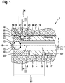
- Fig. 1 shows an arrangement 1 with a valve 2 and a mounting body 3 in an excerpt, schematic sectional view according to a first embodiment.
- the valve 2 serves to meter a fluid, which is preferably a fuel, in particular a gasoline or a gasoline-containing fuel. However, in a correspondingly modified embodiment, the valve 2 can also be used for gaseous fuels and also for other liquid or gaseous fluids.
- the mounting body 3 is configured in this embodiment as a cylinder head 3 for an internal combustion engine.
- the mounting body 3 has a mounting hole 4, wherein in the case of an internal combustion engine usually further such mounting holes 4 are provided, which may be configured as cylinder bores.
- the valve 2 has a valve housing 5, which comprises a plurality of housing parts 6, 7.
- the housing part 6 is formed in this embodiment as a valve seat body 6.
- the housing part 7 is formed as a nozzle body 7, on which the valve seat body 6 is fixed.
- a valve closing body 10 which is connected to the valve needle 9, cooperates with a formed on the valve seat body 6 valve seat surface 11 to a sealing seat.
- a plurality of injection holes 12 are provided on the valve seat body 6, via which the fluid, that is to say here the fuel, is injected or blown from a space 13 in the interior of the valve 2 into a space 14 when the sealing seat is open.
- the space 14 is formed in this embodiment as a combustion chamber 14. In a modified embodiment and / or another application, it may be in the space 14 and the interior 14 of a pipe or the like, are passed through the example, exhaust gases.
- the valve housing 5 has an outer side 15 which, in this exemplary embodiment, has a substantially cylindrical jacket-shaped design.
- an annular groove 16 is configured on the nozzle body 7, in which an annular sealing element 17 is inserted with a rectangular cross-section.
- the sealing element 17 allows a seal between the Valve housing 5 and the mounting hole 4.
- the outer surface 18 is configured on the valve seat body 6.
- a recess 20 is formed in the valve seat body 6, which is realized for example by a blind hole 20. Further, within the outer surface 18, a shallow recess 21 is formed.
- a spring element 25 is arranged in the recess 20. Furthermore, at the point 19, a locking means 26 designed as a spherical locking element 26 is arranged, which is partially located in the recess 20. The locking element 26 is acted upon by the spring element 25 in a radial direction 27 which is perpendicular to the axis 8. The locking element 26 is in this case movable in and against the radial direction 27.
- a captive 28 is provided for the locking element 26.
- the captive 28 is formed as a sheet member 28 having a central recess 29.
- the central recess 29 is in this case designed such that the movement of the locking element 26 in the radial direction 27 is limited so that the locking element 26 can protrude radially beyond the outer surface 18, but not quite fall out.
- Fig. 2 shows a section through the in Fig. 1 illustrated arrangement 1 according to the first embodiment along the section line designated II.
- alignment bores 30, 31 are shown on the valve seat body 6, by means of which an axis 32 is determined.
- the axis 32 is in this case oriented perpendicular to the axis (longitudinal axis) 8.
- the axis 32 here represents the desired mounting position for the valve 2 relative to the mounting hole 4 of the mounting body 3.
- the locking member 26 engages in a groove 33 formed on the mounting body 3 in the region of the mounting hole 4.
- the groove 33 in this case extends coaxially to the axis 8.
- the groove 33 extends along the axis 8 over a limited area 34.
- the limited area 34 in this case allows a certain axial compensation, for example, to compensate for manufacturing tolerances and temperature-related component expansions.
- a joining direction 35 ( Fig. 1 ).
- the groove 33 has opposite to the joining direction 35 on a slope 36.
- the bevel 36 allows disassembly of the valve 2, since upon withdrawal of the valve 2 against the joining direction 35, the spherical locking element 26 is pressed via the slope 36 against the bias of the spring element 25 in the recess 20.
- Fig. 3 shows the in Fig. 2 illustrated arrangement 1 according to a second embodiment of the invention during assembly.
- the valve needle 9 is not shown here.
- a sleeve 37 is provided which is inserted into the recess 20 of the housing part 6.
- the sleeve 37 accommodates both the spring element 25 and the spherical locking element 26.
- an assembly 38 is formed which comprises the sleeve 37, the spring element 25 and the locking element 26.
- the captive 28 for the locking member 26 is integrated in this embodiment in the assembly 38. This allows an additional sheet metal element or the like, as in the reference to the Fig. 1 and 2 described embodiment, omitted.
- the integration of the captive 28 in the assembly 38 is carried out in this embodiment, characterized in that an edge 28 of the sleeve 37 is at least partially flanged by crimping.
- a welded joint, as in the case of the Fig. 1 and 2 described embodiment for connecting the captive 28 is provided with the valve 2, this can be omitted.
- This can also account for the shallow recess 21, in which the basis of the Fig. 1 and 2 described embodiment, the captive formed from a sheet 28 is sunk.
- valve 2 is inserted in the joining direction 35 in the mounting hole 4 of the mounting body 3.
- an angle 39 is predetermined, by which the valve 2 counter to a serving for mounting direction of rotation 40 relative to the end position, as shown in FIG Fig. 2 is shown, is twisted.
- a desired value for the angle 39 is in this case predetermined so that the point 19 at which the locking element 26 is located, although as close as possible opposite to the direction of rotation 40 of the groove 33, but at the same time there are no special requirements for the positioning accuracy for this assembly step .
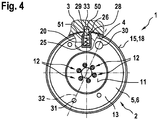
- Fig. 4 shows the in Fig. 2 illustrated arrangement 1 according to a third embodiment in the mounted state.
- the locking element 26 is formed as a locking pin 26.
- the locking pin 26 in this case has a rounded head 50 which protrudes radially over the outer surface 18 in the mounted state, ie in the state used for locking, and engages in the groove 33.
- the locking element 26 in this embodiment, a collar 51.
- the rounded head 50 the engagement in the groove 33 is improved. In this case, a play-free locking can be achieved.
- the rounded head 50 facilitates, in cooperation with the optionally provided bevel 36 on the groove 33, in the Fig. 1 is illustrated, a possible disassembly of the valve. 2
- Fig. 5 shows the in Fig. 1 illustrated arrangement 1 according to a fourth embodiment.
- the locking means 26 which is provided on the outer surface 18, formed as Ausrichtnase 26.
- the locking means 26 is permanently on the outer surface 18 out.
- the groove 33 of the mounting hole 4 must be designed to be continuous in the joining direction 35 at least up to the mounting position for joining.
- the groove 33 extends in the joining direction 35 even up to the combustion chamber 14.
- the sealing element 17 is adapted to the groove 33 configured. This means that the sealing element 17 also seals the groove 33.
- the alignment nose 26 is formed on the housing part 6.
- locking means 26 is designed as a separate component, which is used, for example, stationary in a recess at the point 19.
- such a locking means 26 may also be configured with a rounded head 50, wherein instead of a movable mounting a fixed attachment is realized.
- Fig. 6 shows a section through the in Fig. 5 illustrated arrangement 1 according to the fourth embodiment along the section line designated by VI.
- the valve needle 9 is not shown here.
- Ein Industriesschrägen 53, 54 are formed, which simplify the insertion into the groove 33. Accordingly, it is also conceivable that insertion bevels are provided on the groove 33 of the mounting body 3 in order to simplify the assembly.
- the groove 33 and designed as Ausrichtnase 26 locking means 26 are designed so that the desired positioning accuracy in terms of a possible play in and against the direction of rotation 40 is achieved. It is understood that in this embodiment, the assembly after the axial joining has no assembly step in which the valve 2 is rotated relative to the mounting body 3 in the direction of rotation 40.
- the locking means 26 is in a joining portion 55 between the sealing element 17 and the combustion chamber 14, in which between the outer side 15 and the mounting hole 4, at least in the region of the outer surface 18 is a small distance to the locking in and against the To allow direction of rotation 40 by the interaction of the locking member 26 with the groove 33.
- the joining portion 55 is located between the sealing element 17 and the combustion chamber 14, wherein the joining portion 55 may optionally extend beyond the sealing member 17 against the joining direction 35, if there is also a corresponding small distance between the outer side 15 and the mounting hole 4 ,
- the joining section 55 is thus a section 55 of the valve housing 5, which is located in the mounting hole 4 in the mounted state.
- the locking means 26 is arranged at the point 19 within or at the edge of the outer surface 18 of the joining portion 55 so that it protrudes radially over the outer surface 18 permanently or at least in the state used for locking.
- the locking means 26 may also protrude radially beyond the outer surface 18 at a different time, in particular before assembly.
- a rotation for the valve 2 can be formed, with an axial movement of the locking means 26 in the groove 33 is still possible.
- a movable locking element 26 is provided, then, among other things by the choice of the locking pin 26 and the spring element 25, a large stroke and / or a large holding force against unwanted twisting can be achieved. This can be advantageous, for example, in an operation in which high vibration loads occur.
- a locking means 26 designed as a locking pin 26 can be used without a sleeve 37 in the recess 20, wherein a captive 28 can be formed by a perforated plate member 28.
- the sealing element 17 may be formed for example of Teflon.
Landscapes
- Engineering & Computer Science (AREA)
- Chemical & Material Sciences (AREA)
- Combustion & Propulsion (AREA)
- Mechanical Engineering (AREA)
- General Engineering & Computer Science (AREA)
- Fuel-Injection Apparatus (AREA)
- Valve Housings (AREA)
Applications Claiming Priority (1)
| Application Number | Priority Date | Filing Date | Title |
|---|---|---|---|
| DE102015222478.3A DE102015222478A1 (de) | 2015-11-13 | 2015-11-13 | Ventil zum Zumessen eines Fluids und Anordnung mit solch einem Ventil |
Publications (2)
| Publication Number | Publication Date |
|---|---|
| EP3168454A1 true EP3168454A1 (fr) | 2017-05-17 |
| EP3168454B1 EP3168454B1 (fr) | 2019-01-09 |
Family
ID=57249747
Family Applications (1)
| Application Number | Title | Priority Date | Filing Date |
|---|---|---|---|
| EP16197710.3A Active EP3168454B1 (fr) | 2015-11-13 | 2016-11-08 | Vanne de dosage de fluide et dispositif comprenant une telle vanne |
Country Status (3)
| Country | Link |
|---|---|
| EP (1) | EP3168454B1 (fr) |
| CN (1) | CN106837646A (fr) |
| DE (1) | DE102015222478A1 (fr) |
Families Citing this family (1)
| Publication number | Priority date | Publication date | Assignee | Title |
|---|---|---|---|---|
| CN110822106B (zh) * | 2018-08-09 | 2022-10-28 | 罗伯特·博世有限公司 | 用于制冷阀的传动装置和制冷阀 |
Citations (4)
| Publication number | Priority date | Publication date | Assignee | Title |
|---|---|---|---|---|
| DE19950761A1 (de) | 1999-10-21 | 2001-04-26 | Bosch Gmbh Robert | Brennstoffeinspritzventil |
| EP2068022A1 (fr) * | 2007-12-07 | 2009-06-10 | Continental Automotive GmbH | Agencement de couplage et ensemble de connexion |
| US20100300408A1 (en) * | 2009-05-29 | 2010-12-02 | Cummins Intellectual Properties, Inc. | Fuel injector, clamping assembly and method of mounting a fuel injector |
| DE102014201735A1 (de) * | 2014-01-31 | 2015-08-06 | Robert Bosch Gmbh | Hochdruckpumpe |
Family Cites Families (4)
| Publication number | Priority date | Publication date | Assignee | Title |
|---|---|---|---|---|
| CN2916162Y (zh) * | 2006-06-23 | 2007-06-27 | 李张太 | 油嘴总程旋装式单缸柴油机缸盖 |
| DE102012208087B4 (de) * | 2012-05-15 | 2024-03-14 | Man Energy Solutions Se | Kraftstoffeinspritzdüse |
| CN103104392B (zh) * | 2012-12-08 | 2014-12-03 | 宁波市鄞州云帆工程咨询有限公司 | 具有反向锁固功能的喷油器底座 |
| CN104832342A (zh) * | 2015-03-12 | 2015-08-12 | 重庆科克发动机技术有限公司 | 一种发动机喷油器的安装定位结构 |
-
2015
- 2015-11-13 DE DE102015222478.3A patent/DE102015222478A1/de not_active Withdrawn
-
2016
- 2016-11-08 EP EP16197710.3A patent/EP3168454B1/fr active Active
- 2016-11-11 CN CN201611272994.8A patent/CN106837646A/zh active Pending
Patent Citations (4)
| Publication number | Priority date | Publication date | Assignee | Title |
|---|---|---|---|---|
| DE19950761A1 (de) | 1999-10-21 | 2001-04-26 | Bosch Gmbh Robert | Brennstoffeinspritzventil |
| EP2068022A1 (fr) * | 2007-12-07 | 2009-06-10 | Continental Automotive GmbH | Agencement de couplage et ensemble de connexion |
| US20100300408A1 (en) * | 2009-05-29 | 2010-12-02 | Cummins Intellectual Properties, Inc. | Fuel injector, clamping assembly and method of mounting a fuel injector |
| DE102014201735A1 (de) * | 2014-01-31 | 2015-08-06 | Robert Bosch Gmbh | Hochdruckpumpe |
Also Published As
| Publication number | Publication date |
|---|---|
| DE102015222478A1 (de) | 2017-05-18 |
| EP3168454B1 (fr) | 2019-01-09 |
| CN106837646A (zh) | 2017-06-13 |
Similar Documents
| Publication | Publication Date | Title |
|---|---|---|
| DE19758817B4 (de) | Halterung für ein Brennstoffeinspritzventil am Zylinderkopf einer Brennkraftmaschine | |
| DE4131537A1 (de) | Brennstoffverteiler | |
| WO2008083881A1 (fr) | Injecteur pour injecter du carburant dans les chambres de combustion des moteurs à combustion interne | |
| DE10152415A1 (de) | Brennstoffeinspritzventil | |
| DE10215980A1 (de) | Leckageanschluss für einen Kraftstoffinjektor | |
| EP2786010B1 (fr) | Soupape de dosage d'un milieu en écoulement | |
| DE102008035087B4 (de) | Einspritzventil | |
| EP3168454B1 (fr) | Vanne de dosage de fluide et dispositif comprenant une telle vanne | |
| DE602004003896T2 (de) | Flüssigkeitseinspritzventil und sein Herstellungverfahren | |
| EP2582962B1 (fr) | Élément d'amortissement pour ensemble culasse de moteur à combustion interne et injecteur | |
| WO2010031628A1 (fr) | Soupape d'injection de combustible | |
| DE3734587A1 (de) | Kraftstoff-einspritzduese fuer brennkraftmaschinen | |
| EP1043496B1 (fr) | Injecteur de combustible pour un moteur à combustion interne | |
| DE102007053800A1 (de) | Kraftstoffsystem einer Brennkraftmaschine | |
| EP1576279B1 (fr) | Soupape d'injection de carburant | |
| CH693962A5 (de) | Kraftstoffinjektor fuer eine Brennkraftmaschine. | |
| DE102010034411B4 (de) | Brennkraftmaschine mit Einspritzventil | |
| DE102020207472A1 (de) | Komponente für eine Einspritzanlage und Einspritzanlage für gemischverdichtende, fremdgezündete Brennkraftmaschinen | |
| EP2519730B1 (fr) | Injecteur de fluide | |
| DE102006009069A1 (de) | Brennstoffeinspritzventil | |
| DE10102192A1 (de) | Vorrichtung zur Halterung von Einspritzelementen im Zylinderkopf einer Brennkraftmaschine | |
| DE102019219628A1 (de) | Ventil zum Zumessen eines Fluids, insbesondere Brennstoffeinspritzventil | |
| DE102005047352A1 (de) | Hochdruck-Einspritzsystem | |
| DE102005022535A1 (de) | Einspritzventil und Düsenbaugruppe für ein Einspritzventil | |
| DE102020215193A1 (de) | Komponente für eine Einspritzanlage und Einspritzanlage für gemischverdichtende, fremdgezündete Brennkraftmaschinen |
Legal Events
| Date | Code | Title | Description |
|---|---|---|---|
| PUAI | Public reference made under article 153(3) epc to a published international application that has entered the european phase |
Free format text: ORIGINAL CODE: 0009012 |
|
| STAA | Information on the status of an ep patent application or granted ep patent |
Free format text: STATUS: THE APPLICATION HAS BEEN PUBLISHED |
|
| AK | Designated contracting states |
Kind code of ref document: A1 Designated state(s): AL AT BE BG CH CY CZ DE DK EE ES FI FR GB GR HR HU IE IS IT LI LT LU LV MC MK MT NL NO PL PT RO RS SE SI SK SM TR |
|
| AX | Request for extension of the european patent |
Extension state: BA ME |
|
| STAA | Information on the status of an ep patent application or granted ep patent |
Free format text: STATUS: REQUEST FOR EXAMINATION WAS MADE |
|
| 17P | Request for examination filed |
Effective date: 20171117 |
|
| RBV | Designated contracting states (corrected) |
Designated state(s): AL AT BE BG CH CY CZ DE DK EE ES FI FR GB GR HR HU IE IS IT LI LT LU LV MC MK MT NL NO PL PT RO RS SE SI SK SM TR |
|
| RIC1 | Information provided on ipc code assigned before grant |
Ipc: F02M 61/14 20060101AFI20180531BHEP |
|
| GRAP | Despatch of communication of intention to grant a patent |
Free format text: ORIGINAL CODE: EPIDOSNIGR1 |
|
| STAA | Information on the status of an ep patent application or granted ep patent |
Free format text: STATUS: GRANT OF PATENT IS INTENDED |
|
| INTG | Intention to grant announced |
Effective date: 20180710 |
|
| GRAS | Grant fee paid |
Free format text: ORIGINAL CODE: EPIDOSNIGR3 |
|
| GRAA | (expected) grant |
Free format text: ORIGINAL CODE: 0009210 |
|
| STAA | Information on the status of an ep patent application or granted ep patent |
Free format text: STATUS: THE PATENT HAS BEEN GRANTED |
|
| AK | Designated contracting states |
Kind code of ref document: B1 Designated state(s): AL AT BE BG CH CY CZ DE DK EE ES FI FR GB GR HR HU IE IS IT LI LT LU LV MC MK MT NL NO PL PT RO RS SE SI SK SM TR |
|
| REG | Reference to a national code |
Ref country code: GB Ref legal event code: FG4D Free format text: NOT ENGLISH |
|
| REG | Reference to a national code |
Ref country code: CH Ref legal event code: EP Ref country code: AT Ref legal event code: REF Ref document number: 1087619 Country of ref document: AT Kind code of ref document: T Effective date: 20190115 |
|
| REG | Reference to a national code |
Ref country code: DE Ref legal event code: R096 Ref document number: 502016003128 Country of ref document: DE |
|
| REG | Reference to a national code |
Ref country code: IE Ref legal event code: FG4D Free format text: LANGUAGE OF EP DOCUMENT: GERMAN |
|
| REG | Reference to a national code |
Ref country code: NL Ref legal event code: MP Effective date: 20190109 |
|
| REG | Reference to a national code |
Ref country code: LT Ref legal event code: MG4D |
|
| PG25 | Lapsed in a contracting state [announced via postgrant information from national office to epo] |
Ref country code: NL Free format text: LAPSE BECAUSE OF FAILURE TO SUBMIT A TRANSLATION OF THE DESCRIPTION OR TO PAY THE FEE WITHIN THE PRESCRIBED TIME-LIMIT Effective date: 20190109 |
|
| PG25 | Lapsed in a contracting state [announced via postgrant information from national office to epo] |
Ref country code: PT Free format text: LAPSE BECAUSE OF FAILURE TO SUBMIT A TRANSLATION OF THE DESCRIPTION OR TO PAY THE FEE WITHIN THE PRESCRIBED TIME-LIMIT Effective date: 20190509 Ref country code: ES Free format text: LAPSE BECAUSE OF FAILURE TO SUBMIT A TRANSLATION OF THE DESCRIPTION OR TO PAY THE FEE WITHIN THE PRESCRIBED TIME-LIMIT Effective date: 20190109 Ref country code: LT Free format text: LAPSE BECAUSE OF FAILURE TO SUBMIT A TRANSLATION OF THE DESCRIPTION OR TO PAY THE FEE WITHIN THE PRESCRIBED TIME-LIMIT Effective date: 20190109 Ref country code: PL Free format text: LAPSE BECAUSE OF FAILURE TO SUBMIT A TRANSLATION OF THE DESCRIPTION OR TO PAY THE FEE WITHIN THE PRESCRIBED TIME-LIMIT Effective date: 20190109 Ref country code: NO Free format text: LAPSE BECAUSE OF FAILURE TO SUBMIT A TRANSLATION OF THE DESCRIPTION OR TO PAY THE FEE WITHIN THE PRESCRIBED TIME-LIMIT Effective date: 20190409 Ref country code: SE Free format text: LAPSE BECAUSE OF FAILURE TO SUBMIT A TRANSLATION OF THE DESCRIPTION OR TO PAY THE FEE WITHIN THE PRESCRIBED TIME-LIMIT Effective date: 20190109 Ref country code: FI Free format text: LAPSE BECAUSE OF FAILURE TO SUBMIT A TRANSLATION OF THE DESCRIPTION OR TO PAY THE FEE WITHIN THE PRESCRIBED TIME-LIMIT Effective date: 20190109 |
|
| PG25 | Lapsed in a contracting state [announced via postgrant information from national office to epo] |
Ref country code: IS Free format text: LAPSE BECAUSE OF FAILURE TO SUBMIT A TRANSLATION OF THE DESCRIPTION OR TO PAY THE FEE WITHIN THE PRESCRIBED TIME-LIMIT Effective date: 20190509 Ref country code: RS Free format text: LAPSE BECAUSE OF FAILURE TO SUBMIT A TRANSLATION OF THE DESCRIPTION OR TO PAY THE FEE WITHIN THE PRESCRIBED TIME-LIMIT Effective date: 20190109 Ref country code: BG Free format text: LAPSE BECAUSE OF FAILURE TO SUBMIT A TRANSLATION OF THE DESCRIPTION OR TO PAY THE FEE WITHIN THE PRESCRIBED TIME-LIMIT Effective date: 20190409 Ref country code: GR Free format text: LAPSE BECAUSE OF FAILURE TO SUBMIT A TRANSLATION OF THE DESCRIPTION OR TO PAY THE FEE WITHIN THE PRESCRIBED TIME-LIMIT Effective date: 20190410 Ref country code: LV Free format text: LAPSE BECAUSE OF FAILURE TO SUBMIT A TRANSLATION OF THE DESCRIPTION OR TO PAY THE FEE WITHIN THE PRESCRIBED TIME-LIMIT Effective date: 20190109 Ref country code: HR Free format text: LAPSE BECAUSE OF FAILURE TO SUBMIT A TRANSLATION OF THE DESCRIPTION OR TO PAY THE FEE WITHIN THE PRESCRIBED TIME-LIMIT Effective date: 20190109 |
|
| REG | Reference to a national code |
Ref country code: DE Ref legal event code: R097 Ref document number: 502016003128 Country of ref document: DE |
|
| PG25 | Lapsed in a contracting state [announced via postgrant information from national office to epo] |
Ref country code: SK Free format text: LAPSE BECAUSE OF FAILURE TO SUBMIT A TRANSLATION OF THE DESCRIPTION OR TO PAY THE FEE WITHIN THE PRESCRIBED TIME-LIMIT Effective date: 20190109 Ref country code: RO Free format text: LAPSE BECAUSE OF FAILURE TO SUBMIT A TRANSLATION OF THE DESCRIPTION OR TO PAY THE FEE WITHIN THE PRESCRIBED TIME-LIMIT Effective date: 20190109 Ref country code: AL Free format text: LAPSE BECAUSE OF FAILURE TO SUBMIT A TRANSLATION OF THE DESCRIPTION OR TO PAY THE FEE WITHIN THE PRESCRIBED TIME-LIMIT Effective date: 20190109 Ref country code: DK Free format text: LAPSE BECAUSE OF FAILURE TO SUBMIT A TRANSLATION OF THE DESCRIPTION OR TO PAY THE FEE WITHIN THE PRESCRIBED TIME-LIMIT Effective date: 20190109 Ref country code: CZ Free format text: LAPSE BECAUSE OF FAILURE TO SUBMIT A TRANSLATION OF THE DESCRIPTION OR TO PAY THE FEE WITHIN THE PRESCRIBED TIME-LIMIT Effective date: 20190109 Ref country code: EE Free format text: LAPSE BECAUSE OF FAILURE TO SUBMIT A TRANSLATION OF THE DESCRIPTION OR TO PAY THE FEE WITHIN THE PRESCRIBED TIME-LIMIT Effective date: 20190109 |
|
| PLBE | No opposition filed within time limit |
Free format text: ORIGINAL CODE: 0009261 |
|
| STAA | Information on the status of an ep patent application or granted ep patent |
Free format text: STATUS: NO OPPOSITION FILED WITHIN TIME LIMIT |
|
| 26N | No opposition filed |
Effective date: 20191010 |
|
| PG25 | Lapsed in a contracting state [announced via postgrant information from national office to epo] |
Ref country code: SI Free format text: LAPSE BECAUSE OF FAILURE TO SUBMIT A TRANSLATION OF THE DESCRIPTION OR TO PAY THE FEE WITHIN THE PRESCRIBED TIME-LIMIT Effective date: 20190109 |
|
| PGFP | Annual fee paid to national office [announced via postgrant information from national office to epo] |
Ref country code: IT Payment date: 20191130 Year of fee payment: 4 Ref country code: FR Payment date: 20191121 Year of fee payment: 4 |
|
| PG25 | Lapsed in a contracting state [announced via postgrant information from national office to epo] |
Ref country code: TR Free format text: LAPSE BECAUSE OF FAILURE TO SUBMIT A TRANSLATION OF THE DESCRIPTION OR TO PAY THE FEE WITHIN THE PRESCRIBED TIME-LIMIT Effective date: 20190109 |
|
| REG | Reference to a national code |
Ref country code: CH Ref legal event code: PL |
|
| PG25 | Lapsed in a contracting state [announced via postgrant information from national office to epo] |
Ref country code: MC Free format text: LAPSE BECAUSE OF FAILURE TO SUBMIT A TRANSLATION OF THE DESCRIPTION OR TO PAY THE FEE WITHIN THE PRESCRIBED TIME-LIMIT Effective date: 20190109 Ref country code: LU Free format text: LAPSE BECAUSE OF NON-PAYMENT OF DUE FEES Effective date: 20191108 Ref country code: LI Free format text: LAPSE BECAUSE OF NON-PAYMENT OF DUE FEES Effective date: 20191130 Ref country code: CH Free format text: LAPSE BECAUSE OF NON-PAYMENT OF DUE FEES Effective date: 20191130 |
|
| REG | Reference to a national code |
Ref country code: BE Ref legal event code: MM Effective date: 20191130 |
|
| PG25 | Lapsed in a contracting state [announced via postgrant information from national office to epo] |
Ref country code: IE Free format text: LAPSE BECAUSE OF NON-PAYMENT OF DUE FEES Effective date: 20191108 |
|
| PG25 | Lapsed in a contracting state [announced via postgrant information from national office to epo] |
Ref country code: BE Free format text: LAPSE BECAUSE OF NON-PAYMENT OF DUE FEES Effective date: 20191130 |
|
| PG25 | Lapsed in a contracting state [announced via postgrant information from national office to epo] |
Ref country code: CY Free format text: LAPSE BECAUSE OF FAILURE TO SUBMIT A TRANSLATION OF THE DESCRIPTION OR TO PAY THE FEE WITHIN THE PRESCRIBED TIME-LIMIT Effective date: 20190109 |
|
| PG25 | Lapsed in a contracting state [announced via postgrant information from national office to epo] |
Ref country code: SM Free format text: LAPSE BECAUSE OF FAILURE TO SUBMIT A TRANSLATION OF THE DESCRIPTION OR TO PAY THE FEE WITHIN THE PRESCRIBED TIME-LIMIT Effective date: 20190109 |
|
| GBPC | Gb: european patent ceased through non-payment of renewal fee |
Effective date: 20201108 |
|
| PG25 | Lapsed in a contracting state [announced via postgrant information from national office to epo] |
Ref country code: HU Free format text: LAPSE BECAUSE OF FAILURE TO SUBMIT A TRANSLATION OF THE DESCRIPTION OR TO PAY THE FEE WITHIN THE PRESCRIBED TIME-LIMIT; INVALID AB INITIO Effective date: 20161108 Ref country code: MT Free format text: LAPSE BECAUSE OF FAILURE TO SUBMIT A TRANSLATION OF THE DESCRIPTION OR TO PAY THE FEE WITHIN THE PRESCRIBED TIME-LIMIT Effective date: 20190109 |
|
| PG25 | Lapsed in a contracting state [announced via postgrant information from national office to epo] |
Ref country code: FR Free format text: LAPSE BECAUSE OF NON-PAYMENT OF DUE FEES Effective date: 20201130 Ref country code: IT Free format text: LAPSE BECAUSE OF NON-PAYMENT OF DUE FEES Effective date: 20201108 |
|
| PG25 | Lapsed in a contracting state [announced via postgrant information from national office to epo] |
Ref country code: GB Free format text: LAPSE BECAUSE OF NON-PAYMENT OF DUE FEES Effective date: 20201108 |
|
| PG25 | Lapsed in a contracting state [announced via postgrant information from national office to epo] |
Ref country code: MK Free format text: LAPSE BECAUSE OF FAILURE TO SUBMIT A TRANSLATION OF THE DESCRIPTION OR TO PAY THE FEE WITHIN THE PRESCRIBED TIME-LIMIT Effective date: 20190109 |
|
| REG | Reference to a national code |
Ref country code: AT Ref legal event code: MM01 Ref document number: 1087619 Country of ref document: AT Kind code of ref document: T Effective date: 20211108 |
|
| PG25 | Lapsed in a contracting state [announced via postgrant information from national office to epo] |
Ref country code: AT Free format text: LAPSE BECAUSE OF NON-PAYMENT OF DUE FEES Effective date: 20211108 |
|
| PGFP | Annual fee paid to national office [announced via postgrant information from national office to epo] |
Ref country code: DE Payment date: 20240123 Year of fee payment: 8 |