EP3168282B2 - Anlage und verfahren zum herstellen von asphalt - Google Patents
Anlage und verfahren zum herstellen von asphalt Download PDFInfo
- Publication number
- EP3168282B2 EP3168282B2 EP16189027.2A EP16189027A EP3168282B2 EP 3168282 B2 EP3168282 B2 EP 3168282B2 EP 16189027 A EP16189027 A EP 16189027A EP 3168282 B2 EP3168282 B2 EP 3168282B2
- Authority
- EP
- European Patent Office
- Prior art keywords
- unit
- exhaust gas
- drying
- installation
- gas
- Prior art date
- Legal status (The legal status is an assumption and is not a legal conclusion. Google has not performed a legal analysis and makes no representation as to the accuracy of the status listed.)
- Active
Links
Images
Classifications
-
- E—FIXED CONSTRUCTIONS
- E01—CONSTRUCTION OF ROADS, RAILWAYS, OR BRIDGES
- E01C—CONSTRUCTION OF, OR SURFACES FOR, ROADS, SPORTS GROUNDS, OR THE LIKE; MACHINES OR AUXILIARY TOOLS FOR CONSTRUCTION OR REPAIR
- E01C19/00—Machines, tools or auxiliary devices for preparing or distributing paving materials, for working the placed materials, or for forming, consolidating, or finishing the paving
- E01C19/02—Machines, tools or auxiliary devices for preparing or distributing paving materials, for working the placed materials, or for forming, consolidating, or finishing the paving for preparing the materials
- E01C19/10—Apparatus or plants for premixing or precoating aggregate or fillers with non-hydraulic binders, e.g. with bitumen, with resins, i.e. producing mixtures or coating aggregates otherwise than by penetrating or surface dressing; Apparatus for premixing non-hydraulic mixtures prior to placing or for reconditioning salvaged non-hydraulic compositions
-
- F—MECHANICAL ENGINEERING; LIGHTING; HEATING; WEAPONS; BLASTING
- F26—DRYING
- F26B—DRYING SOLID MATERIALS OR OBJECTS BY REMOVING LIQUID THEREFROM
- F26B23/00—Heating arrangements
- F26B23/001—Heating arrangements using waste heat
- F26B23/002—Heating arrangements using waste heat recovered from dryer exhaust gases
-
- F—MECHANICAL ENGINEERING; LIGHTING; HEATING; WEAPONS; BLASTING
- F26—DRYING
- F26B—DRYING SOLID MATERIALS OR OBJECTS BY REMOVING LIQUID THEREFROM
- F26B23/00—Heating arrangements
- F26B23/001—Heating arrangements using waste heat
- F26B23/007—Heating arrangements using waste heat recovered from the dried product
-
- F—MECHANICAL ENGINEERING; LIGHTING; HEATING; WEAPONS; BLASTING
- F26—DRYING
- F26B—DRYING SOLID MATERIALS OR OBJECTS BY REMOVING LIQUID THEREFROM
- F26B23/00—Heating arrangements
- F26B23/02—Heating arrangements using combustion heating
- F26B23/022—Heating arrangements using combustion heating incinerating volatiles in the dryer exhaust gases, the produced hot gases being wholly, partly or not recycled into the drying enclosure
-
- F—MECHANICAL ENGINEERING; LIGHTING; HEATING; WEAPONS; BLASTING
- F26—DRYING
- F26B—DRYING SOLID MATERIALS OR OBJECTS BY REMOVING LIQUID THEREFROM
- F26B3/00—Drying solid materials or objects by processes involving the application of heat
- F26B3/02—Drying solid materials or objects by processes involving the application of heat by convection, i.e. heat being conveyed from a heat source to the materials or objects to be dried by a gas or vapour, e.g. air
- F26B3/04—Drying solid materials or objects by processes involving the application of heat by convection, i.e. heat being conveyed from a heat source to the materials or objects to be dried by a gas or vapour, e.g. air the gas or vapour circulating over or surrounding the materials or objects to be dried
-
- Y—GENERAL TAGGING OF NEW TECHNOLOGICAL DEVELOPMENTS; GENERAL TAGGING OF CROSS-SECTIONAL TECHNOLOGIES SPANNING OVER SEVERAL SECTIONS OF THE IPC; TECHNICAL SUBJECTS COVERED BY FORMER USPC CROSS-REFERENCE ART COLLECTIONS [XRACs] AND DIGESTS
- Y02—TECHNOLOGIES OR APPLICATIONS FOR MITIGATION OR ADAPTATION AGAINST CLIMATE CHANGE
- Y02P—CLIMATE CHANGE MITIGATION TECHNOLOGIES IN THE PRODUCTION OR PROCESSING OF GOODS
- Y02P70/00—Climate change mitigation technologies in the production process for final industrial or consumer products
- Y02P70/10—Greenhouse gas [GHG] capture, material saving, heat recovery or other energy efficient measures, e.g. motor control, characterised by manufacturing processes, e.g. for rolling metal or metal working
Definitions
- the invention relates to a plant for producing asphalt and a method for reducing exhaust gas and/or odor emissions during the production of asphalt.
- the core of the invention is that an exhaust gas source is connected to a heating unit. Exhaust gases caused by the exhaust gas source can be fed into the heating unit via an exhaust gas line and burned there. In particular, all exhaust gases from the system are fed into the heating unit and burned there. This reduces exhaust gas and/or odor emissions to the environment. Pollutants in the exhaust gas are, for example, hydrocarbons and/or odor carriers. In particular, the hydrocarbons are largely burned in the heating unit. The pollutant load is reduced. The proportion of pollutants in the burned gas is reduced by at least 50%, in particular at least 60%, in particular at least 70%, in particular at least 80% and in particular by at least 90%. The production of asphalt is improved from an ecological point of view.
- the afterburning of the exhaust gas in the heating unit generates heat, which can be used efficiently to dry a first material in a first drying unit.
- the production of asphalt is improved economically.
- the first material that is dried in the first drying unit is white mineral.
- the heat supplied by the heating unit is sufficient to ensure the drying of the first material.
- the heating unit serves to heat a gas, which is in particular a gas mixture and which may still contain fine particles and very fine particles.
- the system has at least one exhaust gas source. In particular, several exhaust gas sources can be provided.
- the system in which the at least one exhaust gas source is designed with an extraction hood with an integrated particle separation unit, ensures that the exhaust gas flow fed to the heating unit essentially contains fine particles with a particle size that is in particular smaller than 100 ⁇ m, in particular smaller than 63 ⁇ m and in particular smaller than 20 ⁇ m. Larger particles can be effectively and directly separated with the extraction hood.
- a heating unit according to claim 2 enables effective gas heating.
- gas supplied can be heated directly by means of a heat source, in particular a hot gas burner. Because the gas supplied is exhaust gas, any pollutants and/or odor carriers contained therein are immediately afterburned. Afterburning in the hot gas generator is simplified.
- a first drying unit according to claim 3 can be designed in a simplified manner.
- a rotary kiln can be supplied with the heated gas from the heating unit, whereby a separate heat source for the first drying unit can be dispensed with.
- fire protection fittings in the rotary kiln are dispensable.
- Throwing plates can be provided in the rotary kiln for better heat transfer of the first material.
- a first drying unit according to claim 4 enables improved flexibility of use.
- the fact that a first drying burner is provided ensures reliable operation of the system. In the event that the heat provided by the heating unit is not sufficient for drying the first material, the first drying burner can be activated.
- a filter system according to claim 5 enables an additional reduction of pollutants in the exhaust gas stream leaving the system.
- fine particles can be separated separately.
- a system according to claim 6 enables the immediate filtering out of residual fine particles.
- a system according to claim 7 enables a particularly effective reduction of pollutant emissions.
- the at least one exhaust gas source is a processing unit for a second material.
- the second material is in particular old asphalt granulate, which typically contains additives, although not all additives are known a priori. Unknown additives and/or other known additives that arise as a result of possible heating of the old asphalt granulate, as well as odor and pollutant emissions, are fed to the heating unit and burned there. It is also possible for old asphalt granulate to be used cold, i.e. without prior heating. The resulting vapors and pollutants can also be burned in the heating unit.
- a system according to claim 8 enables the integration of further, different types of exhaust gas sources.
- the system it is possible for the system to have a large number of different exhaust gas sources, which are connected to the heating unit, for example, via a particularly branched exhaust gas line network. It is particularly possible to combine the exhaust gases from all exhaust gas sources to be fed into the heating unit and burned there.
- a gas conveying unit according to claim 9 enables targeted air flow generation along the exhaust pipe.
- a closing element according to claim 10 enables switchable activation and deactivation of line sections of line sections of the exhaust line.
- the closing element which is designed in particular as a quick-closing flap, thus enables a safety function. In the event of a fire, the closing element can immediately close the exhaust line and thus prevent a fire from spreading to other system components. It is also possible to use the closing element to connect only those system components to the heating unit that are intended to release exhaust gases to the heating unit. Unnecessary system components can be immediately separated by the closing element along the exhaust line, i.e. deactivated in terms of exhaust gases.
- a system with a control unit according to claim 11 enables the conveying capacity of the gas conveying unit to be directly influenced.
- the gas conveying unit is designed as an exhaust fan, whereby the speed of the exhaust fan can be regulated via the control unit. The higher the speed of the exhaust fan, the greater the volume flow of air conveyed.
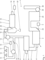
- the system 1 shown is used to produce asphalt.
- the system 1 comprises a first drying unit 2 in which white mineral is dried as the first material.
- the first drying unit 2 is designed as a rotary kiln.
- the first drying unit 2 is operated in a countercurrent process.
- White mineral is fed from a white mineral source 3 to the front of the first drying unit 2 and discharged again at the opposite front.
- the heated white mineral is then fed for further processing, in particular mixed with other components.
- a first drying burner 4 is arranged on the front at which the heated white mineral leaves the first drying unit 2.
- the first drying burner 4 is used to directly heat the first material in the first drying unit 2.
- the first drying burner 4 can also be omitted.
- a hot gas generator 6 is connected to the front side of the material discharge on the first drying unit 2 via a hot gas line 5.
- a heat source 7 in the form of a hot gas burner is connected to the front side of the hot gas generator 6.
- the hot gas generator 6 is arranged in particular at ground level.
- the hot gas generator 6 is arranged together with the heat source 7 directly on the floor. Such an arrangement is uncomplicated and advantageous in particular for static reasons.
- the hot gas generator 6 is operated in the counter/cross-flow process.
- the hot gas generator 6 and the heat source 7 form a heating unit 8 which serves to heat a gas.
- the gas is in particular a gas mixture.
- the gas to be heated is fed to the heating unit 8, in particular to the hot gas generator 6, via an exhaust gas line 9.
- Such a hot gas generator 6 with heat source 7 is in terms of its structure and its function, i.e. its mode of operation, in the DE 10 2015 217 845.5 described, to which reference is hereby expressly made.
- a first exhaust gas source in the form of a processing unit 10 for old asphalt granulate as a second material, a loading silo 11, a mixing unit 12 and a bitumen unit 13 are connected to the heating unit 8 via the exhaust gas line 9. More or fewer exhaust gas sources than those mentioned can also be provided.
- each exhaust source is assigned a separate gas conveying unit.
- the gas conveying units 14 are each designed in particular as an extraction fan. The extraction fan is arranged along the exhaust line 9 between the respective exhaust source 10 or 11, 12, 13 and the heating unit 8. The extraction fans are integrated into the exhaust line 9.
- the gas conveying units 14 are in signal connection with a control unit 15.
- Closing elements 16 are arranged along the exhaust pipe 9. According to the embodiment shown, the closing elements 16 are each designed as quick-closing flaps.
- the quick-closing caps serve for switchable closing of the exhaust pipe 9, in particular a respective line section of the exhaust pipe 9.
- the closing elements 16 are each in signal connection with the control unit 15. In a closed switching state, the closing element 16 seals off the line cross-section of the exhaust pipe. A gas flow at closed locking element is prevented.
- the processing unit 10 has a used asphalt drying drum 17 that is operated using the direct current method. Used asphalt material is fed from a used asphalt source 18 to the front of the used asphalt drying drum 17.
- the used asphalt drying drum is a second drying unit.
- a second drying burner 19 is arranged on the second drying unit.
- the second drying burner 19 is arranged on the front of the material inlet.
- An extraction hood 20 is provided on the opposite front, where the material outlet of the used asphalt material is provided.
- the suction hood 20 serves to extract gas containing particles from the old asphalt drying drum 17.
- the suction hood 20 has an integrated particle separation unit, which is designed passively as a flow influencing unit and in particular has a flow guide element 21 in the form of a pivoting flap, which is also referred to as a pendulum flap.
- the structure and operation of the suction hood 20 are described in the German patent application DE 10 2015 217 845.5 described, to which reference is hereby expressly made.
- Particles separated in the suction hood 20 are collected in a lower area in a collecting container 22.
- the collecting container 22 can also be used to receive dried old asphalt granulate from the old asphalt drying drum 17. This means that the material outlet from the old asphalt drying drum 17 can open into the collecting container 22.
- the respective material can also be fed directly to further processing via a weighing device, in particular a mixing unit.
- the extraction hood 20 is directly connected to the hot gas generator 6 via the exhaust pipe 9.
- An exhaust air line 23 is connected to the front side of the material inlet of the first drying unit 2. Exhaust air from the first drying unit 2 is conveyed to a filter system 24 via the exhaust air line 23.
- the filter system 24 serves to separate fine particles. The separated exhaust air can be released into the ambient air via an exhaustor 25 and a chimney 26.
- Old asphalt granulate is heated in the processing unit 10.
- the old asphalt drying drum 17 is operated in a cocurrent process.
- Exhaust gas from the old asphalt drying drum 17 is cleaned in the separation unit 20, in particular by separating fine particles.
- the exhaust gas cleaned in this way is conveyed via the exhaust line 9 by means of the gas conveying unit 14 into the hot gas generator 6.
- pollutant components and/or odor carriers of the exhaust gas are afterburned.
- the afterburning cleans the exhaust gas by reducing the pollutant particles and odor carriers still contained in it.
- the afterburning generates additional heat.
- the heated gas from the hot gas generator 6 is fed to the first drying unit 2 via the hot gas line 5.
- the first drying unit 2 is operated in a countercurrent process. White mineral is dried in the first drying unit 2.
- the exhaust air from the first drying unit 2 is conveyed via the exhaust air line 23 into the filter system 24 and from there released into the environment via the exhaustor 25 and the chimney 26.
- the processing unit 10 can be fluidically separated from the hot gas generator via the closing element 16.
- the closing element 16 By closing the closing element 16 assigned to the processing unit 10, a gas flow along the exhaust line 9 from the hot gas generator 6 to the processing unit 10 is prevented.
- the other closing element 16 can be opened in order to fluidically connect the other exhaust gas sources, in particular the loading silo 11, the mixing unit 12 and/or the bitumen unit 13, to the hot gas generator 6 via the exhaust line 9.
- the system 1 can basically be operated in three different operating modes. In a first operating mode, only the processing unit 10 with the old asphalt drying drum 17 is connected to the hot gas generator 6. In a second operating mode, in addition to the exhaust gases from the old asphalt drying drum 17 of the processing unit 10, contaminated air streams from the other exhaust gas sources 11, 12 and/or 13 are also fed to the hot gas generator 6. A third operating mode consists in only contaminated air from the exhaust gas sources 11, 12 and/or 13 being fed to the hot gas generator 6, whereby polluted exhaust gases from the old asphalt drying drum 17 are retained.
- a significant advantage of the system 1 is that existing systems for producing asphalt can be converted to a system 1 according to the invention with little equipment outlay.
- previously known old asphalt drying drums that are operated using the cocurrent process can continue to be operated essentially unchanged.
- Exhaust gases from the old asphalt drying drum 17 are conveyed to the hot gas generator 6 by means of a gas conveying unit 14.
- the hot gas generator 6 all exhaust gases from the system are burned and the heated air or the heated gas mixture is used to dry the white mineral in the first drying unit 2.
Landscapes
- Engineering & Computer Science (AREA)
- Life Sciences & Earth Sciences (AREA)
- Mechanical Engineering (AREA)
- General Engineering & Computer Science (AREA)
- Sustainable Development (AREA)
- Microbiology (AREA)
- Chemical & Material Sciences (AREA)
- Combustion & Propulsion (AREA)
- Architecture (AREA)
- Civil Engineering (AREA)
- Structural Engineering (AREA)
- Road Paving Machines (AREA)
Description
- Die Erfindung betrifft eine Anlage zum Herstellen von Asphalt und ein Verfahren zum Reduzieren von Abgas- und/oder Geruchsemissionen bei der Herstellung von Asphalt.
- Bei der Herstellung von Asphalt werden die Inhaltsstoffe erwärmt und miteinander vermischt. Die Herstellung von Asphalt ist offenbart in
EP 2 835 470 A2 undDE 35 30 248 A1 . Weitere Verfahren zur Erwärmung von Medien sind bekannt ausUS 2015/0093297 A1 undEP 2 213 939 A2 . Bei deren Erwärmung entstehen Abgasemissionen und/oder Geruchsemissionen, die insbesondere durch rezykliertes Altasphaltgranulat und/oder Bitumenmaterial verursacht werden können.
Der Erfindung liegt die Aufgabe zugrunde, bei der Herstellung von Asphalt Abgas- und/oder Geruchsemissionen zu reduzieren. - Die Aufgabe wird durch die Merkmale der Ansprüche 1 und 12 gelöst. Der Kern der Erfindung besteht darin, dass eine Abgasquelle mit einer Erwärmungseinheit verbunden ist. Abgase, die von der Abgasquelle verursacht werden, können über eine Abgasleitung in die Erwärmungseinheit geleitet und dort verbrannt werden. Insbesondere werden sämtliche Abgase der Anlage in die Erwärmungseinheit geführt und dort nachverbrannt. Dadurch sind die Abgas- und/oder Geruchsemissionen an die Umgebung reduziert. Schadstoffe in dem Abgas sind beispielsweise Kohlenwasserstoffe und/oder Geruchsträger. Insbesondere die Kohlenwasserstoffe werden größtenteils in der Erwärmungseinheit nachverbrannt. Die Schadstoffbelastung ist reduziert. Der Anteil der Schadstoffe in dem nachverbrannten Gas ist um mindestens 50 %, insbesondere mindestens 60 %, insbesondere mindestens 70 %, insbesondere mindestens 80 % und insbesondere um mindestens 90 % reduziert. Die Herstellung von Asphalt ist aus ökologischer Sicht verbessert. Zudem wird durch das Nachverbrennen des Abgases in der Erwärmungseinheit Wärme erzeugt, die effizient zum Trocknen eines ersten Materials in einer ersten Trocknungseinheit genutzt werden kann. Das Herstellen von Asphalt ist ökonomisch verbessert. Insbesondere ist das erste Material, das in der ersten Trocknungseinheit getrocknet wird, Weißmineral. Insbesondere ist die von der Erwärmungseinheit zugeführte Wärme ausreichend, um die Trocknung des ersten Materials zu gewährleisten. Die Erwärmungseinheit dient zum Erwärmen eines Gases, das insbesondere ein Gasgemisch ist und das Feinanteile und Feinstanteile noch aufweisen kann. Die Anlage weist mindestens eine Abgasquelle auf. Insbesondere können mehrere Abgasquellen vorgesehen sein.
- Die Anlage, bei der die mindestens eine Abgasquelle mit einer Absaughaube mit einer integrierten Partikelabscheideeinheit ausgeführt ist, gewährleistet, dass der der Erwärmungseinheit zugeführte Abgasstrom im Wesentlichen Feinpartikel enthält mit einer Partikelgröße, die insbesondere kleiner ist als 100 µm, insbesondere kleiner als 63 µm und insbesondere kleiner als 20 µm. Größere Partikel können mit der Absaughaube effektiv und unmittelbar abgeschieden werden.
- Eine Erwärmungseinheit gemäß Anspruch 2 ermöglicht eine effektive Gaserwärmung. In einem Heißgaserzeuger kann mittels einer Wärmequelle, insbesondere einem Heißgas-Brenner, zugeführtes Gas unmittelbar erwärmt werden. Dadurch, dass das zugeführte Gas Abgas ist, werden darin enthaltene Schadstoffe und/oder Geruchsträger unmittelbar nachverbrannt. Die Nachverbrennung in dem Heißgaserzeuger ist vereinfacht.
- Eine erste Trocknungseinheit gemäß Anspruch 3 kann vereinfacht ausgeführt sein. Ein Drehrohrofen kann mit dem erwärmten Gas aus der Erwärmungseinheit versorgt werden, wobei eine eigene, separate Wärmequelle für die erste Trocknungseinheit entfallen kann. In diesem Fall sind Feuerschutzeinbauten in dem Drehrohrofen entbehrlich. In dem Drehrohrofen können Wurfbleche für die bessere Wärmeübertragung des ersten Materials vorgesehen sein.
- Eine erste Trocknungseinheit gemäß Anspruch 4 ermöglicht eine verbesserte Einsatzflexibilität. Dadurch, dass ein erster Trocknungs-Brenner vorgesehen ist, ist ein zuverlässiger Betrieb der Anlage gewährleistet. Für den Fall, dass die von der Erwärmungseinheit zur Verfügung gestellte Wärme für die Trocknung des ersten Materials nicht ausreichend sein sollte, kann der erste Trocknungs-Brenner aktiviert werden.
- Eine Filteranlage gemäß Anspruch 5 ermöglicht eine zusätzliche Reduzierung der Schadstoffe im Abgasstrom, der die Anlage verlässt. Insbesondere können Feinpartikel separat abgeschieden werden.
- Eine Anlage gemäß Anspruch 6 ermöglicht die unmittelbare Ausfilterung von Rest-Feinpartikeln.
- Eine Anlage gemäß Anspruch 7 ermöglicht eine besonders effektive Reduktion der Schadstoffemissionen. Die mindestens eine Abgasquelle ist eine Aufbereitungseinheit für ein zweites Material. Das zweite Material ist insbesondere Altasphaltgranulat, das typischerweise Zuschlagstoffe enthält, wobei a priori nicht alle Zuschlagstoffe bekannt sind. Unbekannte Zuschlagstoffe und/oder weitere bekannte Zuschlagstoffe, die infolge einer möglichen Erwärmung des Altasphaltgranulats entstehen, sowie Geruchs- und Schadstoffemissionen, werden der Erwärmungseinheit zugeführt und dort nachverbrannt. Es ist auch möglich, dass Altasphaltgranulat kalt, also ohne vorherige Erwärmung, verwendet wird. Die dabei entstehenden Dämpfe und Schadstoffe können ebenfalls in der Erwärmungseinheit nachverbrannt werden.
- Eine Anlage gemäß Anspruch 8 ermöglicht die Integration weiterer, verschiedenartiger Abgasquellen. Insbesondere ist es möglich, dass die Anlage eine Vielzahl verschiedener Abgasquellen aufweist, die beispielsweise über ein, insbesondere verzweigtes, Abgasleitungsnetz mit der Erwärmungseinheit verbunden sind. Es ist insbesondere möglich, die Abgase sämtlicher Abgasquellen der Anlage der Erwärmungseinheit zuzuführen und dort zu verbrennen.
- Eine Gasfördereinheit gemäß Anspruch 9 ermöglicht eine gezielte Luftstromerzeugung entlang der Abgasleitung.
- Ein Schließelement gemäß Anspruch 10 ermöglicht ein schaltbares Aktivieren und Deaktivieren von Leitungsabschnitten von Leitungsabschnitten der Abgasleitung. Dadurch ermöglicht das Schließelement, das insbesondere als Schnellschlussklappe ausgeführt ist, eine Sicherheitsfunktion. Bei einem eventuellen Brand kann das Schließelement die Abgasleitung unmittelbar verschließen und damit verhindern, dass sich ein Brand auf weitere Anlagenbestandteile ausbreitet. Es ist zudem möglich, mittels des Schließelements nur die Anlagenbestandteile an die Erwärmungseinheit anzuschließen, die Abgase an die Erwärmungseinheit abgeben sollen. Nicht benötigte Anlagenbestandteile können durch das Schließelement entlang der Abgasleitung unmittelbar abgetrennt, also abgastechnisch deaktiviert werden.
- Eine Anlage mit einer Steuereinheit gemäß Anspruch 11 ermöglicht die unmittelbare Beeinflussung der Förderleistung der Gasfördereinheit. Insbesondere ist die Gasfördereinheit als Absaugventilator ausgeführt, wobei die Drehzahl des Absaugventilators über die Steuereinheit geregelt werden kann. Je größer die Drehzahl des Absaugventilators, desto größer ist der geförderte Luftvolumenstrom.
- Das erfindungsgemäße Verfahren gemäß Anspruch 12 ermöglicht im Wesentlichen die Vorteile, die die erfindungsgemäße Anlage ermöglicht, worauf hiermit verwiesen wird.
- Weitere vorteilhafte Ausgestaltungen, zusätzliche Merkmale und Einzelheiten der Erfindung ergeben sich aus der nachfolgenden Beschreibung eines Ausführungsbeispiels. Es zeigen:
- Fig. 1
- eine schematische Darstellung einer Anlage zur Herstellung von Asphalt gemäß der Erfindung.
- Eine in
Fig. 1 dargestellte Anlage 1 dient zur Herstellung von Asphalt. Die Anlage 1 umfasst eine erste Trocknungseinheit 2, in der Weißmineral als erstes Material getrocknet wird. Die erste Trocknungseinheit 2 ist als Drehrohrofen ausgeführt. Die erste Trocknungseinheit 2 wird im Gegenstromverfahren betrieben. Weißmineral wird aus einer Weißmineralquelle 3 der ersten Trocknungseinheit 2 stirnseitig zugeführt und an der gegenüberliegenden Stirnseite wieder abgeführt. Das erwärmte Weißmineral wird anschließend einer Weiterverarbeitung zugeführt, insbesondere mit weiteren Bestandteilen vermischt. An der Stirnseite, an der das erwärmte Weißmineral die erste Trocknungseinheit 2 verlässt, ist ein erster Trocknungs-Brenner 4 angeordnet. Der erste Trocknungs-Brenner 4 dient zum unmittelbaren Erwärmen des ersten Materials in der ersten Trocknungseinheit 2. Der erste Trocknungs-Brenner 4 kann auch entfallen. - An der Stirnseite des Materialaustrags ist an der ersten Trocknungseinheit 2 über eine Heißgasleitung 5 ein Heißgaserzeuger 6 angeschlossen. An den Heißgaserzeuger 6 ist stirnseitig eine Wärmequelle 7 in Form eines Heißgas-Brenners angeschlossen. Der Heißgaserzeuger 6 ist insbesondere ebenerdig angeordnet. Der Heißgaserzeuger 6 ist zusammen mit der Wärmequelle 7 unmittelbar auf dem Boden angeordnet. Eine derartige Anordnung ist unkompliziert und insbesondere aus statischen Gründen vorteilhaft. Der Heißgaserzeuger 6 wird im Gegen-/Kreuzstrom-Verfahren betrieben. Der Heißgaserzeuger 6 und die Wärmequelle 7 bilden eine Erwärmungseinheit 8, die zum Erwärmen eines Gases dient. Das Gas ist insbesondere ein Gasgemisch. Das zu erwärmende Gas wird der Erwärmungseinheit 8, insbesondere dem Heißgaserzeuger 6, über eine Abgasleitung 9 zugeführt. Ein derartiger Heißgaserzeuger 6 mit Wärmequelle 7 ist bezüglich seines Aufbaus und seiner Funktion, d.h. seiner Betriebsweise, in der
DE 10 2015 217 845.5 beschrieben, worauf hiermit ausdrücklich verwiesen wird. - Über die Abgasleitung 9 sind mit der Erwärmungseinheit 8 eine erste Abgasquelle in Form einer Aufbereitungseinheit 10 für Altasphaltgranulat als zweites Material, ein Verladesilo 11, eine Mischeinheit 12 und eine Bitumeneinheit 13 angeschlossen. Es können auch mehr oder weniger als die genannten Abgasquellen vorgesehen sein.
- Entlang der Abgasleitung 9, die als verzweigtes Abgasleitungsnetz ausgeführt ist, sind zwei Gasfördereinheiten 14 vorgesehen, die zum Erzeugen eines Luftstroms dienen, um Abgase aus den Abgasquellen 10 bis 14 zu der Erwärmungseinheit 8 zu fördern. Gemäß dem gezeigten Ausführungsbeispiel ist eine Gasfördereinheit 14 den Abgasquellen Verladesilo 11, Mischeinheit 12 und Bitumeneinheit 13 zugeordnet. Die andere Gasfördereinheit 14 ist der Aufbereitungseinheit 10 zugeordnet. Es ist auch denkbar, dass jeder Abgasquelle eine separate Gasfördereinheit zugeordnet ist. Die Gasfördereinheiten 14 sind insbesondere jeweils als Absaugventilator ausgeführt. Der Absaugventilator ist entlang der Abgasleitung 9 zwischen der jeweiligen Abgasquelle 10 bzw. 11, 12, 13 und der Erwärmungseinheit 8 angeordnet. Die Absaugventilatoren sind in die Abgasleitung 9 integriert. Die Gasfördereinheiten 14 sind mit einer Steuerungseinheit 15 in Signalverbindung.
- Entlang der Abgasleitung 9 sind Schließelemente 16 angeordnet. Gemäß dem gezeigten Ausführungsbeispiel sind die Schließelemente 16 jeweils als Schnellschlussklappen ausgeführt. Die Schnellschlusskappen dienen zum schaltbaren Schließen der Abgasleitung 9, insbesondere eines jeweiligen Leitungsabschnitts der Abgasleitung 9. Zum schaltbaren Schließen sind die Schließelemente 16 jeweils in Signalverbindung mit der Steuerungseinheit 15. In einem geschlossenen Schaltzustand riegelt das Schließelement 16 den Leitungsquerschnitt der Abgasleitung ab. Ein Gasstrom bei geschlossenem Schließelement ist verhindert.
- Die Aufbereitungseinheit 10 weist gemäß dem gezeigten Ausführungsbeispiel eine Altasphalttrockentrommel 17 auf, die im Gleichstromverfahren betrieben wird. Altasphaltmaterial wird aus einer Altasphaltquelle 18 stirnseitig der Altasphalttrockentrommel 17 zugeführt. Die Altasphalttrockentrommel ist eine zweite Trocknungseinheit. An der zweiten Trocknungseinheit ist ein zweiter Trocknungs-Brenner 19 angeordnet. Der zweite Trocknungs-Brenner 19 ist an der Stirnseite des Materialzulaufs angeordnet. An der gegenüberliegenden Stirnseite, an der der Materialauslauf des Altasphaltmaterials vorgesehen ist, ist eine Absaughaube 20 vorgesehen. Die Absaughaube 20 dient zum Absaugen von partikelhaltigem Gas aus der Altasphalttrockentrommel 17. Die Absaughaube 20 weist eine integrierte Partikelabscheideeinheit auf, die passiv als Strömungsbeeinflussungseinheit ausgeführt ist und insbesondere ein Strömungsleitelement 21 in Form einer schwenkbaren Klappe, die auch als Pendelklappe bezeichnet wird, aufweist. Der Aufbau und die Betriebsweise der Absaughaube 20 sind in der deutschen Patentanmeldung
DE 10 2015 217 845.5 beschrieben, worauf hiermit ausdrücklich verwiesen wird. - In der Absaughaube 20 abgeschiedene Partikel werden in einem unteren Bereich in einem Sammelbehälter 22 gesammelt. Der Sammelbehälter 22 kann auch zur Aufnahme von getrocknetem Altasphaltgranulat aus der Altasphalttrockentrommel 17 dienen. Das bedeutet, dass der Materialauslauf aus der Altasphalttrockentrommel 17 in dem Sammelbehälter 22 münden kann. Zusätzlich oder anstelle des Sammelbehälters 22 kann das jeweilige Material auch einer weiteren Verarbeitung über eine Wiegeeinrichtung unmittelbar zugeführt werden, insbesondere einer Mischeinheit.
- Die Absaughaube 20 ist über die Abgasleitung 9 mit dem Heißgaserzeuger 6 unmittelbar verbunden.
- An der Stirnseite des Materialzulaufs der ersten Trocknungseinheit 2 ist eine Abluftleitung 23 angeschlossen. Über die Abluftleitung 23 wird Abluft aus der ersten Trocknungseinheit 2 in eine Filteranlage 24 gefördert. Die Filteranlage 24 dient zum Abscheiden von Feinpartikeln. Die abgeschiedene Abluft kann über einen Exhaustor 25 und einen Kamin 26 an die Umgebungsluft abgegeben werden.
- Nachfolgend wird ein Verfahren zur Herstellung von Asphalt näher erläutert. In der Aufbereitungseinheit 10 wird Altasphaltgranulat erwärmt. Die Altasphalttrockentrommel 17 wird im Gleichstromverfahren betrieben. Abgas aus der Altasphalttrockentrommel 17 wird in der Abscheideeinheit 20 gereinigt, indem insbesondere Feinpartikel abgeschieden werden. Das so gereinigte Abgas wird über die Abgasleitung 9 mittels der Gasfördereinheit 14 in den Heißgaserzeuger 6 gefördert. In dem Heißgaserzeuger 6 werden Schadstoffanteile und/oder Geruchsträger des Abgases nachverbrannt. Durch die Nachverbrennung wird das Abgas gereinigt, indem noch enthaltene Schadstoffpartikel und Geruchsträger reduziert werden. Durch die Nachverbrennung entsteht zusätzliche Wärme. Das erwärmte Gas aus dem Heißgaserzeuger 6 wird über die Heißgasleitung 5 der ersten Trocknungseinheit 2 zugeführt. Die erste Trocknungseinheit 2 wird im Gegenstromverfahren betrieben. In der ersten Trocknungseinheit 2 wird Weißmineral getrocknet. Die Abluft aus der ersten Trocknungseinheit 2 wird über die Abluftleitung 23 in die Filteranlage 24 gefördert und dort über den Exhaustor 25 und den Kamin 26 an die Umgebung abgegeben.
- Es ist auch denkbar, dass Altasphaltgranulat ohne Vorwärmung bei der Herstellung von Asphalt verwendet werden soll. In diesem Fall kann die Aufbereitungseinheit 10 von dem Heißgaserzeuger über das Schließelement 16 strömungstechnisch getrennt werden. Dadurch, dass das der Aufbereitungseinheit 10 zugeordnete Schließelement 16 geschlossen wird, ist ein Gasstrom entlang der Abgasleitung 9 von dem Heißgaserzeuger 6 zu der Aufbereitungseinheit 10 verhindert. Zusätzlich oder alternativ kann das andere Schließelement 16 geöffnet werden, um die weiteren Abgasquellen, insbesondere das Verladesilo 11, die Mischeinheit 12 und/oder die Bitumeneinheit 13, strömungstechnisch über die Abgasleitung 9 mit dem Heißgaserzeuger 6 zu verbinden.
- Die Anlage 1 kann grundsätzlich in drei verschiedenen Betriebsweisen betrieben werden. In einer ersten Betriebsweise ist ausschließlich die Aufbereitungseinheit 10 mit der Altasphalttrockentrommel 17 mit dem Heißgaserzeuger 6 verbunden. In einer zweiten Betriebsweise werden zusätzlich zu den Abgasen aus der Altasphalttrockentrommel 17 der Aufbereitungseinheit 10 auch kontaminierte Luftströme der weiteren Abgasquellen 11, 12 und/oder 13 dem Heißgaserzeuger 6 zugeführt. Eine dritte Betriebsweise besteht darin, dass ausschließlich kontaminierte Luft der Abgasquellen 11, 12 und/oder 13 dem Heißgaserzeuger 6 zugeführt werden, wobei schadstoffbelastete Abgase aus der Altasphalttrockentrommel 17 zurückgehalten werden.
- Ein wesentlicher Vorteil der Anlage 1 besteht darin, dass bereits bestehende Anlagen zur Herstellung von Asphalt mit geringem apparativem Aufwand zu einer erfindungsgemäßen Anlage 1 umgerüstet werden können. Insbesondere können bislang bekannte Altasphalttrockentrommeln, die im Gleichstromverfahren betrieben werden, im Wesentlichen unverändert weiter betrieben werden. Abgase aus der Altasphalttrockentrommel 17 werden mittels einer Gasfördereinheit 14 in den Heißgaserzeuger 6 gefördert. In dem Heißgaserzeuger 6 werden sämtliche Abgase der Anlage verbrannt und die erwärmte Luft bzw. das erwärmte Gasgemisch zur Trocknung des Weißminerals in der ersten Trocknungseinheit 2 verwendet.
Claims (12)
- Anlage zum Herstellen von Asphalt umfassenda. eine Erwärmungseinheit (8) zum Erwärmen eines Gases,b. eine mit der Erwärmungseinheit (8) über eine Gasleitung (5) verbundene erste Trocknungseinheit (2) zum Trocknen eines ersten Materials,c. zusätzlich zu der ersten Trocknungseinheit (2) mindestens eine Abgasquelle (10, 11, 12, 13), die über eine Abgasleitung (9) mit der Erwärmungseinheit (8) verbunden ist,wobei die mindestens eine Abgasquelle (10) eine Absaughaube (20) mit integrierter Partikelabscheideeinheit aufweist.
- Anlage gemäß Anspruch 1, dadurch gekennzeichnet, dass die Erwärmungseinheit (8) einen Heißgaserzeuger (6) und eine Wärmequelle (6), insbesondere einen Heißgas-Brenner, aufweist.
- Anlage gemäß einem der vorstehenden Ansprüche, dadurch gekennzeichnet, dass die erste Trocknungseinheit (2) als Drehrohrofen ausgeführt ist, der insbesondere mehrere Wurfbleche aufweist.
- Anlage gemäß einem der vorstehenden Ansprüche, dadurch gekennzeichnet, dass die erste Trocknungseinheit (2) einen ersten Trocknungs-Brenner (4) aufweist.
- Anlage gemäß einem der vorstehenden Ansprüche, gekennzeichnet durch eine Filteranlage (24) zum Abscheiden von Feinpartikeln, wobei die Filteranlage (24) insbesondere einen Exhaustor (25) und insbesondere einen Kamin (26) aufweist.
- Anlage gemäß Anspruch 5, dadurch gekennzeichnet, dass die Filteranlage (24) an die erste Trocknungseinheit (2) angeschlossen ist.
- Anlage gemäß einem der vorstehenden Ansprüche, dadurch gekennzeichnet, dass die mindestens eine Abgasquelle (10) als Aufbereitungseinheit für ein zweites Material ausgeführt ist.
- Anlage gemäß einem der vorstehenden Ansprüche, dadurch gekennzeichnet, dass die mindestens eine Abgasquelle ein Verladesilo (11), eine Mischeinheit (12) und/oder eine Bitumeneinheit (13) ist.
- Anlage gemäß einem der vorstehenden Ansprüche, gekennzeichnet durch eine Gasfördereinheit (14) zum Erzeugen eines Gasstroms von der mindestens einen Abgasquelle (10, 11, 12, 13) zu der Erwärmungseinheit (8), wobei die Gasfördereinheit (14) insbesondere als Absaugventilator ausgeführt ist und wobei der Absaugventilator insbesondere entlang der Abgasleitung (9) zwischen der mindestens einen Abgasquelle (10, 11, 12, 13) und der Erwärmungseinheit (8) angeordnet ist.
- Anlage gemäß Anspruch 9, gekennzeichnet durch ein der eine Gasfördereinheit (14) zugeordnetes Schließelement (16) zum schaltbaren Schließen der Abgasleitung (9).
- Anlage gemäß Anspruch 9 oder 10, gekennzeichnet durch eine Steuerungseinheit (15) zum Steuern des Gasstroms entlang der Abgasleitung (9), wobei die Steuerungseinheit (15) mit der Gasfördereinheit (14) und/oder mit dem Schließelement (16) unmittelbar in Signalverbindung steht.
- Verfahren zur Reduktion von Abgas- und/oder Geruchsemissionen bei der Herstellung von Asphalt umfassend- Zuführen von Abgas mindestens einer Abgasquelle (10, 11, 12, 13) über eine Abgasleitung (9) in eine Erwärmungseinheit (8), wobei Partikel mit einer Partikelgröße von mindestens 100 µm in dem Abgasstrom der mindestens einen Abgasquelle (10) mittels einer integrierten Partikelabscheideeinheit einer Absaughaube (20) abgeschieden werden, bevor der Abgasstrom der Erwärmungseinheit (8) zugeführt wird,- Verbrennen von Schadstoffanteilen und/oder Geruchsträgern im Abgas in der Erwärmungseinheit (8),- Erwärmen von Gas in der Erwärmungseinheit (8),- Zuführen des erwärmten Gases über eine Gasleitung (5) in eine erste Trocknungseinheit (2), wobei die erste Trocknungseinheit (2) zusätzlich zu der mindestens einen Abgasquelle angeordnet ist,- Trocknen eines ersten Materials in der ersten Trocknungseinheit (2).
Priority Applications (1)
| Application Number | Priority Date | Filing Date | Title |
|---|---|---|---|
| PL16189027T PL3168282T3 (pl) | 2015-11-12 | 2016-09-15 | Instalacja i sposób wytwarzania asfaltu |
Applications Claiming Priority (1)
| Application Number | Priority Date | Filing Date | Title |
|---|---|---|---|
| DE102015222284.5A DE102015222284A1 (de) | 2015-11-12 | 2015-11-12 | Anlage und Verfahren zum Herstellen von Asphalt |
Publications (3)
| Publication Number | Publication Date |
|---|---|
| EP3168282A1 EP3168282A1 (de) | 2017-05-17 |
| EP3168282B1 EP3168282B1 (de) | 2018-12-12 |
| EP3168282B2 true EP3168282B2 (de) | 2024-10-09 |
Family
ID=57042653
Family Applications (1)
| Application Number | Title | Priority Date | Filing Date |
|---|---|---|---|
| EP16189027.2A Active EP3168282B2 (de) | 2015-11-12 | 2016-09-15 | Anlage und verfahren zum herstellen von asphalt |
Country Status (7)
| Country | Link |
|---|---|
| EP (1) | EP3168282B2 (de) |
| DE (1) | DE102015222284A1 (de) |
| DK (1) | DK3168282T4 (de) |
| ES (1) | ES2713000T3 (de) |
| FI (1) | FI3168282T4 (de) |
| PL (1) | PL3168282T3 (de) |
| TR (1) | TR201903363T4 (de) |
Families Citing this family (2)
| Publication number | Priority date | Publication date | Assignee | Title |
|---|---|---|---|---|
| DE102021210662B4 (de) * | 2021-09-24 | 2025-07-10 | Benninghoven Zweigniederlassung Der Wirtgen Mineral Technologies Gmbh | Vorrichtung und Verfahren zum Trocknen von Material sowie Asphaltmischanlage mit einer derartigen Vorrichtung |
| CZ310284B6 (cs) * | 2023-12-08 | 2025-01-22 | Kovosta - fluid, akciová společnost | Sestava, zařízení a způsob pro vedení vzduchu do rektifikační nebo skladovací nádrže na tekutý asfalt |
Family Cites Families (19)
| Publication number | Priority date | Publication date | Assignee | Title |
|---|---|---|---|---|
| US4211490A (en) | 1976-05-10 | 1980-07-08 | Astec, Industries, Inc. | Drum mix asphalt plant with fiber filter dust collector |
| US4190370A (en) | 1978-11-24 | 1980-02-26 | Astec Industries, Inc. | Asphalt plant with improved temperature control system |
| US4477250A (en) | 1983-03-07 | 1984-10-16 | Mechtron International Corporation | Asphalt recycle plant and method |
| US4715720A (en) | 1984-11-05 | 1987-12-29 | Astec Industries, Inc. | Drum mix asphalt plant with knock-out box and separate pugmill coater |
| DE3530248A1 (de) * | 1985-08-23 | 1987-03-26 | Bayerische Asphalt Mischwerke | Verfahren und vorrichtung zur aufbereitung von bituminoesem mischgut |
| US5201839A (en) | 1989-05-15 | 1993-04-13 | Cmi Corporation | Countercurrent drum mixer with second heat source |
| US5344229A (en) | 1989-07-31 | 1994-09-06 | Cyclean, Inc. | Angle and velocity adjustment of a hot mix asphalt drum when output gas temperatures are uneven |
| US5174650A (en) | 1990-07-23 | 1992-12-29 | Cedarapids, Inc. | Dual drum recycle asphalt drying and mixing method and apparatus |
| US5334012A (en) | 1990-12-27 | 1994-08-02 | Astec Industries, Inc. | Combustion chamber having reduced NOx emissions |
| US5397177A (en) | 1992-02-03 | 1995-03-14 | Swisher, Jr.; George W. | Asphalt production plant having a two-burner dryer with increased exhaust capacity |
| ATE195176T1 (de) | 1993-07-02 | 2000-08-15 | Ammann U Maschf Ag | Trocknung und/oder erhitzung von rieselfähigem material |
| US6478461B1 (en) | 2000-01-14 | 2002-11-12 | Rap Technologies, Inc. | Transportable hot-mix asphalt manufacturing and pollution control system |
| US7566162B1 (en) | 2006-03-07 | 2009-07-28 | Astec, Inc. | Apparatus and method for a hot mix asphalt plant using a high percentage of recycled asphalt products |
| DE102009007725A1 (de) * | 2009-01-28 | 2010-09-09 | Kba-Metalprint Gmbh | Verfahren zum Betreiben einer Oxidationsanlage sowie Oxidationsanlage |
| US9855677B2 (en) * | 2013-07-29 | 2018-01-02 | Astec, Inc. | Method and apparatus for making asphalt concrete using aggregate material from a plurality of material streams |
| TWI519746B (zh) * | 2013-09-30 | 2016-02-01 | 台橡股份有限公司 | 環保系統及其在工廠的應用 |
| DE102013224910A1 (de) | 2013-12-04 | 2015-06-11 | Benninghoven GmbH & Co. KG Mülheim | Vorrichtung und Verfahren zum Erwärmen von Altasphalt-Granulat zur Herstellung von Asphalt |
| DE102015217844A1 (de) | 2015-08-26 | 2017-03-02 | Benninghoven GmbH & Co. KG Mülheim | Brenner-Schutzvorrichtung, Anlage zum Erwärmen von Material umfassend eine derartige Brenner-Schutzvorrichtung sowie Verfahren zum Schützen eines Brenners an einer nachhitzenden Einrichtung vor Überhitzung |
| EP3135996A1 (de) | 2015-08-26 | 2017-03-01 | Benninghoven GmbH & Co.KG Mülheim | Brenner-schutzvorrichtung, anlage zum erwärmen von material umfassend eine derartige brenner-schutzvorrichtung sowie verfahren zum schützen eines brenners an einer nachhitzenden einrichtung vor überhitzung |
-
2015
- 2015-11-12 DE DE102015222284.5A patent/DE102015222284A1/de active Pending
-
2016
- 2016-09-15 DK DK16189027.2T patent/DK3168282T4/da active
- 2016-09-15 ES ES16189027T patent/ES2713000T3/es active Active
- 2016-09-15 EP EP16189027.2A patent/EP3168282B2/de active Active
- 2016-09-15 PL PL16189027T patent/PL3168282T3/pl unknown
- 2016-09-15 TR TR2019/03363T patent/TR201903363T4/tr unknown
- 2016-09-15 FI FIEP16189027.2T patent/FI3168282T4/fi active
Also Published As
| Publication number | Publication date |
|---|---|
| DK3168282T4 (da) | 2024-11-11 |
| FI3168282T4 (fi) | 2024-11-12 |
| EP3168282B1 (de) | 2018-12-12 |
| TR201903363T4 (tr) | 2019-04-22 |
| ES2713000T3 (es) | 2019-05-17 |
| PL3168282T3 (pl) | 2019-05-31 |
| DK3168282T3 (en) | 2019-03-25 |
| EP3168282A1 (de) | 2017-05-17 |
| DE102015222284A1 (de) | 2017-05-18 |
Similar Documents
| Publication | Publication Date | Title |
|---|---|---|
| DE102017212046B4 (de) | Weißmineral-Trockentrommel zum Erwärmen von Weißmineral zum Herstellen von Asphalt sowie Anlage mit einer derartigen Weißmineral-Trockentrommel | |
| EP2388542B1 (de) | Verfahren und Vorrichtung zur kontinuierlichen Trocknung von Schüttgut, insbesondere von Holzfasern und/oder Holzspänen | |
| EP0519225B1 (de) | Verfahren und Vorrichtung zum Reinigen von Abgasen aus Ofenanlagen | |
| DE102014218344B4 (de) | Verfahren und Anlage zum Abtrennen von Verunreinigungen aus Prozessabluft | |
| DE3623939C2 (de) | ||
| DE102015217845B4 (de) | Absaughaube zum Absaugen von Gas sowie Anlage zum Erwärmen von Material für die Asphaltherstellung umfassend eine derartige Absaughaube | |
| WO1990004470A1 (de) | Verfahren und vorrichtung zur aufarbeitung kontaminierter böden | |
| EP3168282B2 (de) | Anlage und verfahren zum herstellen von asphalt | |
| EP0359931A1 (de) | Verfahren zur Trennung von dampfförmigen Schwermetallverbindungen von einem Trägergas und Vorrichtung zur Durchführung des Verfahrens | |
| DE102015202698B4 (de) | Verfahren zur Reinigung von Abgasen bei der thermischen Aufarbeitung von Mineralstoffen | |
| WO2017173555A1 (de) | Verfahren zur erhitzung von granuliertem recyclingasphaltmaterial und trommeltrockner zur durchführung des verfahrens | |
| EP3327349B1 (de) | Heissgaserzeuger zum erwärmen von gas sowie anlage für die asphaltherstellung mit einem derartigen heissgaserzeuger | |
| WO2014037237A1 (de) | Vorrichtung und verfahren zur verarbeitung von ersatzbrennstoffen | |
| DE2949720A1 (de) | Verfahren und vorrichtung zum trocknen und erhitzen von feuchter kohle | |
| EP2889537B1 (de) | Verbrennungsanlage mit einer Trocknungsanlage | |
| EP0274037A1 (de) | Verfahren und Vorrichtung zur Trennung von Partikeln | |
| EP2846088B1 (de) | Rauchgasreinigungseinrichtung für Kleinfeuerungsanlagen | |
| DE102006045791B4 (de) | Verfahren und Anordnung zur Reduzierung des Schadstoffaustrags in der Abluft von Walzwerken und deren Verwendung | |
| EP2437016B1 (de) | Trocknertrommel für hausmüll und verfahren zum trocknen von hausmüll | |
| DE102014115854A1 (de) | Verfahren zur Handhabung von Schlacke und Rostdurchfall einer Müllverbrennungsanlage sowie Müllverbrennungsanlage | |
| DE9014249U1 (de) | Vorrichtung zur Dekontaminierung von schadstoffbelasteten Massen, Böden o.dgl. | |
| EP0024634A1 (de) | Verfahren und Vorrichtung zum Abreinigen der Rauchgase einer Aufbereitungsanlage für bituminöses Mischgut | |
| DE102017105094B4 (de) | Temperiervorrichtung für oberflächenbehandelte Gegenstände wie Fahrzeugteile | |
| WO2016071131A1 (de) | Vorrichtung und verfahren zum abscheiden von kondensierbaren stoffen aus einem abluftstrom | |
| EP3108951A1 (de) | Luftfilteranlage |
Legal Events
| Date | Code | Title | Description |
|---|---|---|---|
| PUAI | Public reference made under article 153(3) epc to a published international application that has entered the european phase |
Free format text: ORIGINAL CODE: 0009012 |
|
| STAA | Information on the status of an ep patent application or granted ep patent |
Free format text: STATUS: THE APPLICATION HAS BEEN PUBLISHED |
|
| AK | Designated contracting states |
Kind code of ref document: A1 Designated state(s): AL AT BE BG CH CY CZ DE DK EE ES FI FR GB GR HR HU IE IS IT LI LT LU LV MC MK MT NL NO PL PT RO RS SE SI SK SM TR |
|
| AX | Request for extension of the european patent |
Extension state: BA ME |
|
| STAA | Information on the status of an ep patent application or granted ep patent |
Free format text: STATUS: REQUEST FOR EXAMINATION WAS MADE |
|
| 17P | Request for examination filed |
Effective date: 20170725 |
|
| RBV | Designated contracting states (corrected) |
Designated state(s): AL AT BE BG CH CY CZ DE DK EE ES FI FR GB GR HR HU IE IS IT LI LT LU LV MC MK MT NL NO PL PT RO RS SE SI SK SM TR |
|
| GRAP | Despatch of communication of intention to grant a patent |
Free format text: ORIGINAL CODE: EPIDOSNIGR1 |
|
| STAA | Information on the status of an ep patent application or granted ep patent |
Free format text: STATUS: GRANT OF PATENT IS INTENDED |
|
| INTG | Intention to grant announced |
Effective date: 20180706 |
|
| RAP1 | Party data changed (applicant data changed or rights of an application transferred) |
Owner name: BENNINGHOVEN GMBH & CO. KG |
|
| GRAS | Grant fee paid |
Free format text: ORIGINAL CODE: EPIDOSNIGR3 |
|
| GRAA | (expected) grant |
Free format text: ORIGINAL CODE: 0009210 |
|
| STAA | Information on the status of an ep patent application or granted ep patent |
Free format text: STATUS: THE PATENT HAS BEEN GRANTED |
|
| AK | Designated contracting states |
Kind code of ref document: B1 Designated state(s): AL AT BE BG CH CY CZ DE DK EE ES FI FR GB GR HR HU IE IS IT LI LT LU LV MC MK MT NL NO PL PT RO RS SE SI SK SM TR |
|
| REG | Reference to a national code |
Ref country code: GB Ref legal event code: FG4D Free format text: NOT ENGLISH |
|
| REG | Reference to a national code |
Ref country code: CH Ref legal event code: EP |
|
| REG | Reference to a national code |
Ref country code: AT Ref legal event code: REF Ref document number: 1075955 Country of ref document: AT Kind code of ref document: T Effective date: 20181215 |
|
| REG | Reference to a national code |
Ref country code: DE Ref legal event code: R096 Ref document number: 502016002781 Country of ref document: DE |
|
| REG | Reference to a national code |
Ref country code: IE Ref legal event code: FG4D Free format text: LANGUAGE OF EP DOCUMENT: GERMAN |
|
| REG | Reference to a national code |
Ref country code: DK Ref legal event code: T3 Effective date: 20190318 |
|
| REG | Reference to a national code |
Ref country code: NL Ref legal event code: MP Effective date: 20181212 |
|
| REG | Reference to a national code |
Ref country code: LT Ref legal event code: MG4D |
|
| PG25 | Lapsed in a contracting state [announced via postgrant information from national office to epo] |
Ref country code: LV Free format text: LAPSE BECAUSE OF FAILURE TO SUBMIT A TRANSLATION OF THE DESCRIPTION OR TO PAY THE FEE WITHIN THE PRESCRIBED TIME-LIMIT Effective date: 20181212 Ref country code: NO Free format text: LAPSE BECAUSE OF FAILURE TO SUBMIT A TRANSLATION OF THE DESCRIPTION OR TO PAY THE FEE WITHIN THE PRESCRIBED TIME-LIMIT Effective date: 20190312 Ref country code: LT Free format text: LAPSE BECAUSE OF FAILURE TO SUBMIT A TRANSLATION OF THE DESCRIPTION OR TO PAY THE FEE WITHIN THE PRESCRIBED TIME-LIMIT Effective date: 20181212 Ref country code: HR Free format text: LAPSE BECAUSE OF FAILURE TO SUBMIT A TRANSLATION OF THE DESCRIPTION OR TO PAY THE FEE WITHIN THE PRESCRIBED TIME-LIMIT Effective date: 20181212 Ref country code: BG Free format text: LAPSE BECAUSE OF FAILURE TO SUBMIT A TRANSLATION OF THE DESCRIPTION OR TO PAY THE FEE WITHIN THE PRESCRIBED TIME-LIMIT Effective date: 20190312 |
|
| REG | Reference to a national code |
Ref country code: ES Ref legal event code: FG2A Ref document number: 2713000 Country of ref document: ES Kind code of ref document: T3 Effective date: 20190517 |
|
| PG25 | Lapsed in a contracting state [announced via postgrant information from national office to epo] |
Ref country code: GR Free format text: LAPSE BECAUSE OF FAILURE TO SUBMIT A TRANSLATION OF THE DESCRIPTION OR TO PAY THE FEE WITHIN THE PRESCRIBED TIME-LIMIT Effective date: 20190313 Ref country code: SE Free format text: LAPSE BECAUSE OF FAILURE TO SUBMIT A TRANSLATION OF THE DESCRIPTION OR TO PAY THE FEE WITHIN THE PRESCRIBED TIME-LIMIT Effective date: 20181212 Ref country code: AL Free format text: LAPSE BECAUSE OF FAILURE TO SUBMIT A TRANSLATION OF THE DESCRIPTION OR TO PAY THE FEE WITHIN THE PRESCRIBED TIME-LIMIT Effective date: 20181212 Ref country code: RS Free format text: LAPSE BECAUSE OF FAILURE TO SUBMIT A TRANSLATION OF THE DESCRIPTION OR TO PAY THE FEE WITHIN THE PRESCRIBED TIME-LIMIT Effective date: 20181212 |
|
| PG25 | Lapsed in a contracting state [announced via postgrant information from national office to epo] |
Ref country code: NL Free format text: LAPSE BECAUSE OF FAILURE TO SUBMIT A TRANSLATION OF THE DESCRIPTION OR TO PAY THE FEE WITHIN THE PRESCRIBED TIME-LIMIT Effective date: 20181212 |
|
| PG25 | Lapsed in a contracting state [announced via postgrant information from national office to epo] |
Ref country code: PT Free format text: LAPSE BECAUSE OF FAILURE TO SUBMIT A TRANSLATION OF THE DESCRIPTION OR TO PAY THE FEE WITHIN THE PRESCRIBED TIME-LIMIT Effective date: 20190412 Ref country code: CZ Free format text: LAPSE BECAUSE OF FAILURE TO SUBMIT A TRANSLATION OF THE DESCRIPTION OR TO PAY THE FEE WITHIN THE PRESCRIBED TIME-LIMIT Effective date: 20181212 |
|
| PG25 | Lapsed in a contracting state [announced via postgrant information from national office to epo] |
Ref country code: SK Free format text: LAPSE BECAUSE OF FAILURE TO SUBMIT A TRANSLATION OF THE DESCRIPTION OR TO PAY THE FEE WITHIN THE PRESCRIBED TIME-LIMIT Effective date: 20181212 Ref country code: RO Free format text: LAPSE BECAUSE OF FAILURE TO SUBMIT A TRANSLATION OF THE DESCRIPTION OR TO PAY THE FEE WITHIN THE PRESCRIBED TIME-LIMIT Effective date: 20181212 Ref country code: IS Free format text: LAPSE BECAUSE OF FAILURE TO SUBMIT A TRANSLATION OF THE DESCRIPTION OR TO PAY THE FEE WITHIN THE PRESCRIBED TIME-LIMIT Effective date: 20190412 Ref country code: EE Free format text: LAPSE BECAUSE OF FAILURE TO SUBMIT A TRANSLATION OF THE DESCRIPTION OR TO PAY THE FEE WITHIN THE PRESCRIBED TIME-LIMIT Effective date: 20181212 Ref country code: SM Free format text: LAPSE BECAUSE OF FAILURE TO SUBMIT A TRANSLATION OF THE DESCRIPTION OR TO PAY THE FEE WITHIN THE PRESCRIBED TIME-LIMIT Effective date: 20181212 |
|
| REG | Reference to a national code |
Ref country code: DE Ref legal event code: R026 Ref document number: 502016002781 Country of ref document: DE |
|
| PLBI | Opposition filed |
Free format text: ORIGINAL CODE: 0009260 |
|
| PLAX | Notice of opposition and request to file observation + time limit sent |
Free format text: ORIGINAL CODE: EPIDOSNOBS2 |
|
| 26 | Opposition filed |
Opponent name: AMMANN SCHWEIZ AG Effective date: 20190902 |
|
| PG25 | Lapsed in a contracting state [announced via postgrant information from national office to epo] |
Ref country code: SI Free format text: LAPSE BECAUSE OF FAILURE TO SUBMIT A TRANSLATION OF THE DESCRIPTION OR TO PAY THE FEE WITHIN THE PRESCRIBED TIME-LIMIT Effective date: 20181212 |
|
| PGFP | Annual fee paid to national office [announced via postgrant information from national office to epo] |
Ref country code: TR Payment date: 20190912 Year of fee payment: 4 |
|
| PLBB | Reply of patent proprietor to notice(s) of opposition received |
Free format text: ORIGINAL CODE: EPIDOSNOBS3 |
|
| PGFP | Annual fee paid to national office [announced via postgrant information from national office to epo] |
Ref country code: ES Payment date: 20191023 Year of fee payment: 4 |
|
| PG25 | Lapsed in a contracting state [announced via postgrant information from national office to epo] |
Ref country code: MC Free format text: LAPSE BECAUSE OF FAILURE TO SUBMIT A TRANSLATION OF THE DESCRIPTION OR TO PAY THE FEE WITHIN THE PRESCRIBED TIME-LIMIT Effective date: 20181212 |
|
| PG25 | Lapsed in a contracting state [announced via postgrant information from national office to epo] |
Ref country code: LU Free format text: LAPSE BECAUSE OF NON-PAYMENT OF DUE FEES Effective date: 20190915 Ref country code: IE Free format text: LAPSE BECAUSE OF NON-PAYMENT OF DUE FEES Effective date: 20190915 |
|
| REG | Reference to a national code |
Ref country code: BE Ref legal event code: MM Effective date: 20190930 |
|
| PG25 | Lapsed in a contracting state [announced via postgrant information from national office to epo] |
Ref country code: BE Free format text: LAPSE BECAUSE OF NON-PAYMENT OF DUE FEES Effective date: 20190930 |
|
| PG25 | Lapsed in a contracting state [announced via postgrant information from national office to epo] |
Ref country code: CY Free format text: LAPSE BECAUSE OF FAILURE TO SUBMIT A TRANSLATION OF THE DESCRIPTION OR TO PAY THE FEE WITHIN THE PRESCRIBED TIME-LIMIT Effective date: 20181212 |
|
| APBM | Appeal reference recorded |
Free format text: ORIGINAL CODE: EPIDOSNREFNO |
|
| APBP | Date of receipt of notice of appeal recorded |
Free format text: ORIGINAL CODE: EPIDOSNNOA2O |
|
| APAH | Appeal reference modified |
Free format text: ORIGINAL CODE: EPIDOSCREFNO |
|
| PG25 | Lapsed in a contracting state [announced via postgrant information from national office to epo] |
Ref country code: MT Free format text: LAPSE BECAUSE OF FAILURE TO SUBMIT A TRANSLATION OF THE DESCRIPTION OR TO PAY THE FEE WITHIN THE PRESCRIBED TIME-LIMIT Effective date: 20181212 Ref country code: HU Free format text: LAPSE BECAUSE OF FAILURE TO SUBMIT A TRANSLATION OF THE DESCRIPTION OR TO PAY THE FEE WITHIN THE PRESCRIBED TIME-LIMIT; INVALID AB INITIO Effective date: 20160915 |
|
| APBQ | Date of receipt of statement of grounds of appeal recorded |
Free format text: ORIGINAL CODE: EPIDOSNNOA3O |
|
| RAP2 | Party data changed (patent owner data changed or rights of a patent transferred) |
Owner name: BENNINGHOVEN ZWEIGNIEDERLASSUNG DER WIRTGEN MINERAL TECHNOLOGIES GMBH |
|
| REG | Reference to a national code |
Ref country code: ES Ref legal event code: FD2A Effective date: 20220114 |
|
| REG | Reference to a national code |
Ref country code: DE Ref legal event code: R081 Ref document number: 502016002781 Country of ref document: DE Owner name: BENNINGHOVEN ZWEIGNIEDERLASSUNG DER WIRTGEN MI, DE Free format text: FORMER OWNER: BENNINGHOVEN GMBH & CO. KG, 54516 WITTLICH, DE |
|
| PG25 | Lapsed in a contracting state [announced via postgrant information from national office to epo] |
Ref country code: ES Free format text: LAPSE BECAUSE OF NON-PAYMENT OF DUE FEES Effective date: 20200916 |
|
| PG25 | Lapsed in a contracting state [announced via postgrant information from national office to epo] |
Ref country code: TR Free format text: LAPSE BECAUSE OF NON-PAYMENT OF DUE FEES Effective date: 20200915 Ref country code: MK Free format text: LAPSE BECAUSE OF FAILURE TO SUBMIT A TRANSLATION OF THE DESCRIPTION OR TO PAY THE FEE WITHIN THE PRESCRIBED TIME-LIMIT Effective date: 20181212 |
|
| REG | Reference to a national code |
Ref country code: AT Ref legal event code: MM01 Ref document number: 1075955 Country of ref document: AT Kind code of ref document: T Effective date: 20210915 |
|
| PG25 | Lapsed in a contracting state [announced via postgrant information from national office to epo] |
Ref country code: AT Free format text: LAPSE BECAUSE OF NON-PAYMENT OF DUE FEES Effective date: 20210915 |
|
| P01 | Opt-out of the competence of the unified patent court (upc) registered |
Effective date: 20230517 |
|
| APBU | Appeal procedure closed |
Free format text: ORIGINAL CODE: EPIDOSNNOA9O |
|
| PLAB | Opposition data, opponent's data or that of the opponent's representative modified |
Free format text: ORIGINAL CODE: 0009299OPPO |
|
| R26 | Opposition filed (corrected) |
Opponent name: AMMANN SCHWEIZ AG Effective date: 20190902 |
|
| PUAH | Patent maintained in amended form |
Free format text: ORIGINAL CODE: 0009272 |
|
| STAA | Information on the status of an ep patent application or granted ep patent |
Free format text: STATUS: PATENT MAINTAINED AS AMENDED |
|
| 27A | Patent maintained in amended form |
Effective date: 20241009 |
|
| AK | Designated contracting states |
Kind code of ref document: B2 Designated state(s): AL AT BE BG CH CY CZ DE DK EE ES FI FR GB GR HR HU IE IS IT LI LT LU LV MC MK MT NL NO PL PT RO RS SE SI SK SM TR |
|
| REG | Reference to a national code |
Ref country code: DE Ref legal event code: R102 Ref document number: 502016002781 Country of ref document: DE |
|
| PGFP | Annual fee paid to national office [announced via postgrant information from national office to epo] |
Ref country code: PL Payment date: 20240808 Year of fee payment: 9 |
|
| REG | Reference to a national code |
Ref country code: DK Ref legal event code: T4 Effective date: 20241106 |
|
| REG | Reference to a national code |
Ref country code: CH Ref legal event code: U11 Free format text: ST27 STATUS EVENT CODE: U-0-0-U10-U11 (AS PROVIDED BY THE NATIONAL OFFICE) Effective date: 20251001 |
|
| PGFP | Annual fee paid to national office [announced via postgrant information from national office to epo] |
Ref country code: FI Payment date: 20250922 Year of fee payment: 10 |
|
| PGFP | Annual fee paid to national office [announced via postgrant information from national office to epo] |
Ref country code: DK Payment date: 20250922 Year of fee payment: 10 |
|
| PGFP | Annual fee paid to national office [announced via postgrant information from national office to epo] |
Ref country code: GB Payment date: 20250923 Year of fee payment: 10 |
|
| PGFP | Annual fee paid to national office [announced via postgrant information from national office to epo] |
Ref country code: FR Payment date: 20250922 Year of fee payment: 10 |
|
| PGFP | Annual fee paid to national office [announced via postgrant information from national office to epo] |
Ref country code: DE Payment date: 20251121 Year of fee payment: 10 |
|
| PGFP | Annual fee paid to national office [announced via postgrant information from national office to epo] |
Ref country code: IT Payment date: 20250930 Year of fee payment: 10 |
|
| PGFP | Annual fee paid to national office [announced via postgrant information from national office to epo] |
Ref country code: CH Payment date: 20251001 Year of fee payment: 10 |