EP3167209B1 - Élément de commande, destiné en particulier à un véhicule automobile - Google Patents
Élément de commande, destiné en particulier à un véhicule automobile Download PDFInfo
- Publication number
- EP3167209B1 EP3167209B1 EP15742196.7A EP15742196A EP3167209B1 EP 3167209 B1 EP3167209 B1 EP 3167209B1 EP 15742196 A EP15742196 A EP 15742196A EP 3167209 B1 EP3167209 B1 EP 3167209B1
- Authority
- EP
- European Patent Office
- Prior art keywords
- handle
- adjustment
- gate
- control element
- element according
- Prior art date
- Legal status (The legal status is an assumption and is not a legal conclusion. Google has not performed a legal analysis and makes no representation as to the accuracy of the status listed.)
- Active
Links
- 230000007935 neutral effect Effects 0.000 claims description 13
- 230000033001 locomotion Effects 0.000 claims description 10
- 238000001746 injection moulding Methods 0.000 claims description 5
- 238000004519 manufacturing process Methods 0.000 claims description 4
- 238000006073 displacement reaction Methods 0.000 claims description 2
- 238000002347 injection Methods 0.000 claims 1
- 239000007924 injection Substances 0.000 claims 1
- 229920001169 thermoplastic Polymers 0.000 claims 1
- 230000006835 compression Effects 0.000 description 4
- 238000007906 compression Methods 0.000 description 4
- 239000000243 solution Substances 0.000 description 4
- 230000005540 biological transmission Effects 0.000 description 3
- 230000008901 benefit Effects 0.000 description 2
- 238000011161 development Methods 0.000 description 2
- 230000018109 developmental process Effects 0.000 description 2
- 239000012815 thermoplastic material Substances 0.000 description 2
- 230000009471 action Effects 0.000 description 1
- 238000005516 engineering process Methods 0.000 description 1
- 238000009434 installation Methods 0.000 description 1
- 230000003993 interaction Effects 0.000 description 1
- 230000007246 mechanism Effects 0.000 description 1
- 238000005457 optimization Methods 0.000 description 1
- 230000009467 reduction Effects 0.000 description 1
- 230000001960 triggered effect Effects 0.000 description 1
Images


Classifications
-
- G—PHYSICS
- G05—CONTROLLING; REGULATING
- G05G—CONTROL DEVICES OR SYSTEMS INSOFAR AS CHARACTERISED BY MECHANICAL FEATURES ONLY
- G05G23/00—Means for ensuring the correct positioning of parts of control mechanisms, e.g. for taking-up play
-
- F—MECHANICAL ENGINEERING; LIGHTING; HEATING; WEAPONS; BLASTING
- F16—ENGINEERING ELEMENTS AND UNITS; GENERAL MEASURES FOR PRODUCING AND MAINTAINING EFFECTIVE FUNCTIONING OF MACHINES OR INSTALLATIONS; THERMAL INSULATION IN GENERAL
- F16H—GEARING
- F16H59/00—Control inputs to control units of change-speed-, or reversing-gearings for conveying rotary motion
- F16H59/02—Selector apparatus
- F16H59/0278—Constructional features of the selector lever, e.g. grip parts, mounting or manufacturing
-
- F—MECHANICAL ENGINEERING; LIGHTING; HEATING; WEAPONS; BLASTING
- F16—ENGINEERING ELEMENTS AND UNITS; GENERAL MEASURES FOR PRODUCING AND MAINTAINING EFFECTIVE FUNCTIONING OF MACHINES OR INSTALLATIONS; THERMAL INSULATION IN GENERAL
- F16H—GEARING
- F16H59/00—Control inputs to control units of change-speed-, or reversing-gearings for conveying rotary motion
- F16H59/02—Selector apparatus
- F16H59/08—Range selector apparatus
- F16H59/10—Range selector apparatus comprising levers
- F16H59/105—Range selector apparatus comprising levers consisting of electrical switches or sensors
-
- F—MECHANICAL ENGINEERING; LIGHTING; HEATING; WEAPONS; BLASTING
- F16—ENGINEERING ELEMENTS AND UNITS; GENERAL MEASURES FOR PRODUCING AND MAINTAINING EFFECTIVE FUNCTIONING OF MACHINES OR INSTALLATIONS; THERMAL INSULATION IN GENERAL
- F16H—GEARING
- F16H59/00—Control inputs to control units of change-speed-, or reversing-gearings for conveying rotary motion
- F16H59/02—Selector apparatus
- F16H59/04—Ratio selector apparatus
- F16H59/044—Ratio selector apparatus consisting of electrical switches or sensors
-
- F—MECHANICAL ENGINEERING; LIGHTING; HEATING; WEAPONS; BLASTING
- F16—ENGINEERING ELEMENTS AND UNITS; GENERAL MEASURES FOR PRODUCING AND MAINTAINING EFFECTIVE FUNCTIONING OF MACHINES OR INSTALLATIONS; THERMAL INSULATION IN GENERAL
- F16H—GEARING
- F16H61/00—Control functions within control units of change-speed- or reversing-gearings for conveying rotary motion ; Control of exclusively fluid gearing, friction gearing, gearings with endless flexible members or other particular types of gearing
- F16H61/24—Providing feel, e.g. to enable selection
-
- G—PHYSICS
- G05—CONTROLLING; REGULATING
- G05G—CONTROL DEVICES OR SYSTEMS INSOFAR AS CHARACTERISED BY MECHANICAL FEATURES ONLY
- G05G5/00—Means for preventing, limiting or returning the movements of parts of a control mechanism, e.g. locking controlling member
- G05G5/05—Means for returning or tending to return controlling members to an inoperative or neutral position, e.g. by providing return springs or resilient end-stops
-
- G—PHYSICS
- G05—CONTROLLING; REGULATING
- G05G—CONTROL DEVICES OR SYSTEMS INSOFAR AS CHARACTERISED BY MECHANICAL FEATURES ONLY
- G05G9/00—Manually-actuated control mechanisms provided with one single controlling member co-operating with two or more controlled members, e.g. selectively, simultaneously
- G05G9/02—Manually-actuated control mechanisms provided with one single controlling member co-operating with two or more controlled members, e.g. selectively, simultaneously the controlling member being movable in different independent ways, movement in each individual way actuating one controlled member only
- G05G9/04—Manually-actuated control mechanisms provided with one single controlling member co-operating with two or more controlled members, e.g. selectively, simultaneously the controlling member being movable in different independent ways, movement in each individual way actuating one controlled member only in which movement in two or more ways can occur simultaneously
- G05G9/047—Manually-actuated control mechanisms provided with one single controlling member co-operating with two or more controlled members, e.g. selectively, simultaneously the controlling member being movable in different independent ways, movement in each individual way actuating one controlled member only in which movement in two or more ways can occur simultaneously the controlling member being movable by hand about orthogonal axes, e.g. joysticks
-
- F—MECHANICAL ENGINEERING; LIGHTING; HEATING; WEAPONS; BLASTING
- F16—ENGINEERING ELEMENTS AND UNITS; GENERAL MEASURES FOR PRODUCING AND MAINTAINING EFFECTIVE FUNCTIONING OF MACHINES OR INSTALLATIONS; THERMAL INSULATION IN GENERAL
- F16H—GEARING
- F16H59/00—Control inputs to control units of change-speed-, or reversing-gearings for conveying rotary motion
- F16H59/02—Selector apparatus
- F16H2059/0295—Selector apparatus with mechanisms to return lever to neutral or datum position, e.g. by return springs
-
- F—MECHANICAL ENGINEERING; LIGHTING; HEATING; WEAPONS; BLASTING
- F16—ENGINEERING ELEMENTS AND UNITS; GENERAL MEASURES FOR PRODUCING AND MAINTAINING EFFECTIVE FUNCTIONING OF MACHINES OR INSTALLATIONS; THERMAL INSULATION IN GENERAL
- F16H—GEARING
- F16H61/00—Control functions within control units of change-speed- or reversing-gearings for conveying rotary motion ; Control of exclusively fluid gearing, friction gearing, gearings with endless flexible members or other particular types of gearing
- F16H61/24—Providing feel, e.g. to enable selection
- F16H2061/243—Cams or detent arrays for guiding and providing feel
-
- G—PHYSICS
- G05—CONTROLLING; REGULATING
- G05G—CONTROL DEVICES OR SYSTEMS INSOFAR AS CHARACTERISED BY MECHANICAL FEATURES ONLY
- G05G1/00—Controlling members, e.g. knobs or handles; Assemblies or arrangements thereof; Indicating position of controlling members
- G05G1/04—Controlling members for hand actuation by pivoting movement, e.g. levers
-
- G—PHYSICS
- G05—CONTROLLING; REGULATING
- G05G—CONTROL DEVICES OR SYSTEMS INSOFAR AS CHARACTERISED BY MECHANICAL FEATURES ONLY
- G05G9/00—Manually-actuated control mechanisms provided with one single controlling member co-operating with two or more controlled members, e.g. selectively, simultaneously
- G05G9/02—Manually-actuated control mechanisms provided with one single controlling member co-operating with two or more controlled members, e.g. selectively, simultaneously the controlling member being movable in different independent ways, movement in each individual way actuating one controlled member only
- G05G9/04—Manually-actuated control mechanisms provided with one single controlling member co-operating with two or more controlled members, e.g. selectively, simultaneously the controlling member being movable in different independent ways, movement in each individual way actuating one controlled member only in which movement in two or more ways can occur simultaneously
- G05G9/047—Manually-actuated control mechanisms provided with one single controlling member co-operating with two or more controlled members, e.g. selectively, simultaneously the controlling member being movable in different independent ways, movement in each individual way actuating one controlled member only in which movement in two or more ways can occur simultaneously the controlling member being movable by hand about orthogonal axes, e.g. joysticks
- G05G2009/0474—Manually-actuated control mechanisms provided with one single controlling member co-operating with two or more controlled members, e.g. selectively, simultaneously the controlling member being movable in different independent ways, movement in each individual way actuating one controlled member only in which movement in two or more ways can occur simultaneously the controlling member being movable by hand about orthogonal axes, e.g. joysticks characterised by means converting mechanical movement into electric signals
- G05G2009/04755—Magnetic sensor, e.g. hall generator, pick-up coil
Definitions
- the invention relates to an actuator according to the preamble of claim 1.
- Actuators such as electrical and / or electronic switching devices designed in the manner of a joystick and / or cursor switch, are used for the manual control and / or triggering of functions in a motor vehicle.
- Such switching devices are used, inter alia, for inputting data for an electrical device by a user, for example in car radios, navigation devices, on-board computers or similar devices in motor vehicles.
- an actuator can also be used as an electronic gear selector switch for a transmission in the motor vehicle controlled by shift-by-wire.
- Such an actuator has a handle which can be designed, for example, in the manner of a selector lever.
- the handle is movably mounted on a carrier such that the handle can be manually adjusted from a neutral position in at least one direction.
- the adjustment of the handle can optionally take place up to an adjustment position.
- a pressure element guided in a slide track of a slide and acted upon by an elastic force interacts with the handle.
- a restoring force in particular acts in the direction of the neutral position on the handle when it is being adjusted. It has been found in such an actuator that the handle has a certain amount of play, particularly in the neutral position.
- Such an actuator is also from the U.S. 5,339,705 A known.
- a means acting on the handle is provided so that the handle is braced in the coulisse to reduce the play of movement of the handle and rests against a housing part.
- Another actuator in which vibrations of the handle are reduced is in the EP 1 980 771 A2 described.
- the invention is based on the object of further developing the actuator in such a way that the play of the handle, in particular in the neutral position, is further reduced.
- the user should be able to operate the handle with as little play as possible and its neutral position (zero position) should have as little play as possible.
- the means acting in a bracing manner on the handle is designed as a cam, the cam being located in the link.
- the cam is also located on a backdrop wall of the backdrop, namely opposite the slide track.
- Such an actuator advantageously offers the user particularly ergonomic operation.
- the adjustment movement can be a pivoting movement of the handle.
- the handle can be adjustable about a first and / or a second pivot axis in a first and / or a second pivot direction.
- the handle can preferably be a pivotable selector lever.
- the carrier for the handle can be designed as a universal joint, in particular in the form of a cardan joint.
- a housing can be provided to protect the actuator.
- the actuator thus forms a preassembled structural unit.
- the handle can comprise a switching shaft pivotably mounted in the carrier.
- the switching shaft can also protrude from the housing for manual operation of the handle by the user.
- the shift shaft can be movably supported in the cross and / or cardan joint by means of a bearing pin.
- the cross and / or cardan joint can in turn be movably supported in the housing by means of pins and / or bearing shells.
- the bearing points for the bearing pin and / or for the cross and / or cardan joint can expediently be designed as clearance fits in a manner that is simple in terms of manufacturing technology. Due to the interaction of the cam with the switching shaft, operation of the actuator is essentially free of play for the user.
- a guide channel for an elastic element for exerting the elastic force and for the pressure element can be located in the selector shaft.
- the elastic element can consist of a compression spring.
- the pressure element can be a pen, a button, a pin or the like.
- the backdrop can consist of thermoplastic material.
- the cam can then be advantageous for the cam to be injected onto the backdrop wall when the backdrop is manufactured by means of injection molding.
- the slide track has a 3D (three-dimensional) contour for generating a haptic for the adjustment of the handle, wherein such a backdrop, which is complex in itself, can nevertheless be produced in a simple manner by injection molding.
- a means for detecting the adjustment and / or the adjustment position can also be provided.
- the means for detecting the adjustment and / or the adjustment positions can expediently comprise a code carrier coding the adjustment and / or the adjustment positions and a sensor determining the coding.
- the code carrier can consist of a magnetic code plate, which in particular contains different, distinguishable magnetic fields
- the sensor can consist of a magnetic sensor, in particular of several Hall sensors, on which a signal reversal occurs when the code plate is shifted .
- the code carrier can be mounted on the switching shaft via a guide component so that the code carrier can be moved by means of the handle in a manner corresponding to the adjustment of the handle.
- the Hall sensors can be attached to a printed circuit board mounted in the housing.
- the aim is to create an input device with the aid of which it is possible to operate a switch in several directions with as little play as possible by means of a control lever.
- the control lever should have as little play as possible in its basic position (zero position).
- the input device can be a gear selector switch as an example.
- a link shape is created for the input device, which braces the control lever or the control shaft in the system. The following is provided for fixing the zero position of the control lever in the input device.
- the switching movement of the control lever is initiated via the switching lever.
- the shift lever sits on the shift shaft.
- the selector shaft is mounted in the universal joint via a bearing pin.
- the universal joint is in turn supported by pins and bearing shells in the lower part of the housing. This storage is used to decouple the system in order to ensure horizontal and vertical switching.
- the individual bearings are designed as clearance fits.
- the switching shaft there is a guide channel for a compression spring and a button, the button being pressed into the slide track of the slide by means of the compression spring.
- the backdrop contains a three-dimensional (3D) contour that creates the feel of the switch.
- the signals are converted by means of a code plate mounted on the selector shaft via a guide component.
- This code plate contains various magnetic fields which, when the code plate is shifted, initiate a signal reversal at various Hall sensors which are attached to a printed circuit board mounted in the lower part of the housing.
- a cam is molded onto the gate wall, which slightly braces the selector shaft against the gate and the remaining components. As a result of this tensioning, the remaining play in the individual bearing points is minimized and thus an optimization of the zero position play of the shift shaft or of the entire shift lever is achieved.
- the selector shaft cannot be deflected when a small force is applied (zero position play).
- An input device has thus been created which has a haptic link with a cam for bracing the system and an improved zero position.
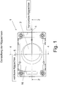
- an actuator 1 can be seen which is used for the manual control of functions in a motor vehicle and is used in particular as a gear selector switch for a shift-by-wire switching device.
- the actuator 1 is provided with a movable handle 2 in the manner of a selector lever.
- the handle 2 is movable on a carrier 3 (see Fig. 2 ) stored in such a way that the handle 2 is adjustable in at least one direction, preferably in two different directions 4, 5 from a neutral position.
- the adjustment of the handle 2 can take place in associated adjustment positions, so that the user can manually adjust the handle 2 into the adjustment positions.
- the handle 2 is adjusted accordingly by the user, the respectively desired functions in the motor vehicle are triggered and / or controlled.
- the handle 2 is designed to be movable by means of pivoting, so that the handle 2 is a pivotable selector lever.
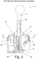
- the handle 2 as in Fig. 2 can be seen, adjustable by means of a bearing pin 6 around a first pivot axis in the first pivot direction 4 and by means of a bearing 7 in the manner of pins and / or bearing shells around a second pivot axis in the second pivot direction 5.
- the carrier 3 for the handle 2 is designed as a cardan joint or a universal joint, as shown in FIG Fig. 3 can be seen in order to allow the pivoting in the respective pivoting direction 4, 5.
- the bearing points for the bearing pin 6 and / or for the bearing 7, that is to say the bearing points for the cross and / or cardan joint 3, are designed as clearance fits.
- a pressure element 8 interacts with the handle 2, the pressure element 8 being guided in a slide track 10 of a slide 9.
- the pressure element 8 has an elastic element 11 and is consequently subjected to an elastic force. Due to the guidance of the pressure element 8 in the slide track 10 when the handle 2 is pivoted, a restoring force acts on the handle 2 in the direction of the neutral position when it is adjusted.
- the handle 2 comprises a shift shaft 12 pivotably mounted in the carrier 3, as can be seen from FIG Fig. 2 sees.
- a guide channel 13 for the elastic element 11 for exerting the elastic force and for the pressure element 8 is located in the shift shaft 12.
- the elastic element 11 in the present case consists of a compression spring.
- the pressure element 8 is a pin, a button or a pin.
- the actuator 1 has according to Fig. 1 furthermore a housing 16, the switching shaft 12 protruding from the housing 16 for manual operation of the handle 2 by the user, as can be seen from FIG Fig. 2 recognizes.
- the cross and / or cardan joint 3 is in turn movably mounted in the housing 16 by means of the bearings 7, although it is mounted in the lower part of the housing 16.
- a cam 14 is located in the backdrop 9.
- the cam 14 acts on the handle 2, more precisely on the switching shaft 12, in such a way that the handle 2 is braced in the link 9 to reduce the play of the handle 2.
- the cam 14 acts on the handle 2 or the switching shaft 12 in such a way that the handle 2 is braced in the direction of adjustment and / or in the direction of the adjustment position. Due to this action, a reduction in the play of movement of the handle 2 is achieved in the neutral position.
- the cam 14 is located on a gate wall 15 of the gate 9, wherein the gate wall 15 of the gate track 10 can be opposite.
- the gate 9 is expediently made of thermoplastic material and is produced by means of injection molding. The cam 14 is then injected onto the gate wall 15 when the gate 9 is manufactured by means of injection molding.
- the slide track 10 has according to Fig. 5 a 3D (three-dimensional) contour for generating a haptic for the adjustment of the handle 2.
- the actuator 1 also has a means for detecting the adjustment and / or the adjustment position or the adjustment positions for the handle 2.
- the means for detecting the adjustment and / or the adjustment positions includes an in which encodes the adjustment and / or the adjustment positions Fig. 4 shown, guided displaceable code carrier 17 and a sensor determining the coding.
- the code carrier 17 consists of a magnetic code plate which contains different, mutually distinguishable magnetic fields for coding the adjustment and / or the adjustment positions, for example by means of corresponding magnetic tracks.
- the sensor not shown further, consists of a magnetic sensor, namely in the present case of several Hall sensors, at which a signal reversal occurs corresponding to the displacement of the code plate 17.
- the code carrier 17 is mounted on the control shaft 12 via a guide component 18, with which the code carrier 17 can be displaced in a manner corresponding to the adjustment of the control shaft 12.
- the Hall sensors are attached to a printed circuit board 19 mounted in the housing 16.
- Such an actuator 1 can be used for a gear selector switch in motor vehicles.
- the handle 2 is the selector lever for the shift-by-wire switching device and the shift-by-wire switching device generates a corresponding position for the handle 2 Signals, the signals used to control the transmission.
- the invention is not restricted to the exemplary embodiment described and illustrated. Rather, it also includes all technical developments within the scope of the invention defined by the patent claims.
- such an actuator 1 can advantageously also be used as an input means for computers, machine tools, household appliances or the like.
Landscapes
- Engineering & Computer Science (AREA)
- General Engineering & Computer Science (AREA)
- Mechanical Engineering (AREA)
- Physics & Mathematics (AREA)
- General Physics & Mathematics (AREA)
- Automation & Control Theory (AREA)
- Mechanical Control Devices (AREA)
- Arrangement Or Mounting Of Control Devices For Change-Speed Gearing (AREA)
- Gear-Shifting Mechanisms (AREA)
- Electric Propulsion And Braking For Vehicles (AREA)
- Steering Controls (AREA)
Claims (9)
- Actionneur, en particulier dispositif de commutation pour la commande manuelle et/ou le déclenchement de fonctions dans un véhicule, avec une manette (2), la manette (2) étant montée sur un support (3) de telle sorte que la manette (2) soit réglable au moins dans une direction (4, 5) à partir d'une position neutre, en particulier dans une position de réglage, avec un élément de pression (8) en interaction avec la manette (2), guidé dans une voie de coulisse (10) d'une coulisse (9) et soumis à une force élastique, en particulier de telle sorte qu'une force de rappel agisse sur la manette (2) en direction de la position neutre lors du réglage, et avec un moyen agissant sur la manette (2) de telle sorte que la manette (2) soit contrainte dans la coulisse (9) pour réduire le jeu de mouvement de la manette (2), caractérisé en ce que
le moyen agissant par contrainte sur la manette (2) est conçu comme une came (14), que la came (14) se trouve dans la coulisse (9) et que la came (14) se trouve sur une paroi de coulisse (15) de la coulisse (9), située à l'opposé de la voie de coulisse (10). - Actionneur conformément à la revendication 1, caractérisé en ce que la came (14) agit sur la manette (2) en position neutre pour réduire le jeu de mouvement de telle sorte que la manette (2) soit contrainte dans la direction du réglage et/ou pour la position de réglage.
- Actionneur conformément à la revendication 1 ou 2, caractérisé en ce que la manette (2) est réglable dans un premier et/ou deuxième sens de pivotement (4, 5) autour d'un premier et/ou deuxième axe de pivotement, que préférablement la manette (2) est un levier sélecteur pivotant et que, plus préférablement le support (3) pour la manette (2) est conçu comme une articulation en croix et/ou à cardan.
- Actionneur conformément à la revendication 1, 2 ou 3, caractérisé en ce qu'un boîtier (16) est prévu, que préférablement la manette (2) comprend un arbre de commande (12) supporté de manière à pouvoir pivoter dans le support (3) et que, plus préférablement l'arbre de commande (12) dépasse du boîtier (16) pour la commande manuelle de la manette (2) par l'utilisateur.
- Actionneur conformément à la revendication 4,
caractérisé en ce que
l'arbre de commande (12) est supporté de façon mobile dans l'articulation en croix et/ou à cardan (3) au moyen d'un axe de support (6), que préférablement l'articulation en croix et/ou à cardan (3) est supportée de façon mobile dans le boîtier (16) au moyen de tourillons et/ou de coussinets de palier et que, plus préférablement les points d'appui pour l'axe de support (6) et/ou pour l'articulation en croix et/ou à cardan (3) sont conçus comme ajustements avec jeu. - Actionneur conformément à l'une des revendications 4 à 5,
caractérisé en ce que
dans l'arbre de commande (12) se trouve un conduit de guidage (13) pour un élément élastique (11) pour exercer la force élastique et pour l'élément de pression (8), que préférablement l'élément élastique (11) se compose d'un ressort de compression et que, plus préférablement l'élément de pression (8) est une tige ou un poussoir. - Actionneur conformément à l'une des revendications 1 à 6, caractérisé en ce que la coulisse (9) est en matière synthétique thermoplastique, que préférablement la came (14) est moulée par procédé de moulage par injection sur la paroi de coulisse (15) lors de la fabrication de la coulisse (9) et que, plus préférablement la voie de coulisse (10) présente un profil en 3 D (tridimensionnel) pour générer une perception haptique pour le réglage de la manette (2).
- Actionneur conformément à l'une des revendications 1 à 7, caractérisé en ce qu'un moyen pour l'enregistrement du réglage et/ou de la position de réglage est prévu et que, préférablement le moyen pour l'enregistrement du réglage et/ou de la position de réglage comprend un porte-code (17) codant le réglage et/ou la position de réglage, ainsi qu'un capteur déterminant le codage, en particulier de telle sorte que, dans le cas de plusieurs positions de réglage, toutes les positions de réglage puissent être enregistrées au moyen du porte-code (17).
- Actionneur conformément à la revendication 8,
caractérisé en ce que
le porte-code (17) se compose d'une plaque de codage magnétique qui contient en particulier plusieurs champs magnétiques, et que le capteur se compose d'un capteur magnétique, en particulier de plusieurs capteurs à effet Hall, sur lesquels il se produit une inversion de signaux dans le cas d'un déplacement du porte-code (17), que préférablement le porte-code (17) est monté sur l'arbre de commande (12) au-dessus d'une pièce de guidage (18) et que, plus préférablement les capteurs à effet Hall sont montés sur un circuit imprimé (19) supporté dans le boîtier (16).
Applications Claiming Priority (2)
| Application Number | Priority Date | Filing Date | Title |
|---|---|---|---|
| DE102014010191 | 2014-07-10 | ||
| PCT/EP2015/065809 WO2016005554A2 (fr) | 2014-07-10 | 2015-07-10 | Élément de commande, destiné en particulier à un véhicule automobile |
Publications (2)
| Publication Number | Publication Date |
|---|---|
| EP3167209A2 EP3167209A2 (fr) | 2017-05-17 |
| EP3167209B1 true EP3167209B1 (fr) | 2021-04-14 |
Family
ID=53758177
Family Applications (1)
| Application Number | Title | Priority Date | Filing Date |
|---|---|---|---|
| EP15742196.7A Active EP3167209B1 (fr) | 2014-07-10 | 2015-07-10 | Élément de commande, destiné en particulier à un véhicule automobile |
Country Status (6)
| Country | Link |
|---|---|
| US (1) | US10865874B2 (fr) |
| EP (1) | EP3167209B1 (fr) |
| JP (1) | JP6605574B2 (fr) |
| CN (1) | CN106687719B (fr) |
| DE (1) | DE102015008517A1 (fr) |
| WO (1) | WO2016005554A2 (fr) |
Families Citing this family (8)
| Publication number | Priority date | Publication date | Assignee | Title |
|---|---|---|---|---|
| JP6775182B2 (ja) * | 2016-06-17 | 2020-10-28 | パナソニックIpマネジメント株式会社 | レバー操作装置 |
| KR101995308B1 (ko) * | 2018-01-16 | 2019-07-03 | 경창산업주식회사 | 전자식 변속 제어 장치 |
| CN108980329B (zh) * | 2018-08-30 | 2019-09-24 | 安徽江淮汽车集团股份有限公司 | 一种选换挡力调节结构 |
| JP7476455B2 (ja) * | 2018-11-09 | 2024-05-01 | 株式会社東海理化電機製作所 | シフト装置 |
| CN111489907B (zh) * | 2019-01-25 | 2022-06-07 | 阿尔卑斯(中国)有限公司 | 拨杆开关 |
| KR20210017359A (ko) * | 2019-08-08 | 2021-02-17 | 현대자동차주식회사 | 차량용 변속레버 장치 |
| CN111536226B (zh) * | 2020-03-31 | 2021-09-21 | 宁波高发汽车控制系统股份有限公司 | 一种多功能汽车换挡手球 |
| CN111702788B (zh) * | 2020-06-18 | 2021-03-19 | 敬科(深圳)机器人科技有限公司 | 并联摇杆机构、使用方法及应用该摇杆机构的机器人 |
Family Cites Families (28)
| Publication number | Priority date | Publication date | Assignee | Title |
|---|---|---|---|---|
| USD289870S (en) * | 1983-10-03 | 1987-05-19 | Berchtold Rainer C F | Video information stand |
| DE3637404A1 (de) * | 1986-11-03 | 1987-11-26 | Bornemann & Haller Kg | Stellantrieb |
| DE4017696A1 (de) * | 1990-06-01 | 1991-12-05 | Bosch Gmbh Robert | Steuergeber |
| US5410931A (en) * | 1990-11-30 | 1995-05-02 | Clark Equipment Belgium, N.V. | Mechanical shifting device |
| JP3074751B2 (ja) * | 1991-03-07 | 2000-08-07 | 日産自動車株式会社 | 自動変速機のシフトデバイス装置 |
| US5339705A (en) * | 1991-03-07 | 1994-08-23 | Nissan Motor Co., Ltd. | Shift device for automatic transmission |
| US5450054A (en) * | 1992-12-08 | 1995-09-12 | Imo Industries, Inc. | Hand-actuatable controller and method for producing control signals using the same |
| DE4306577C2 (de) * | 1993-03-03 | 1998-02-12 | Nbb Nachrichtentech Gmbh | Handsteuergerät mit einem Steuerknüppel |
| JP3458592B2 (ja) | 1996-04-01 | 2003-10-20 | 三菱ふそうトラック・バス株式会社 | 変速操作装置 |
| SE517453C2 (sv) * | 1997-06-27 | 2002-06-11 | Kongsberg Automotive Ab | Manöveranordning |
| US6448670B1 (en) * | 1998-05-12 | 2002-09-10 | Alps Electric Co., Ltd. | Signal input device |
| IT1310136B1 (it) | 1999-08-18 | 2002-02-11 | Fiat Auto Spa | Dispositivo per la selezione delle marce di tipo perfezionato per ilcambio automatico di un autoveicolo. |
| EP2339213B1 (fr) * | 2001-03-02 | 2014-09-03 | Toyota Jidosha Kabushiki Kaisha | Dispositif de changement de vitesse pour une véhicule |
| JP2003154868A (ja) * | 2001-11-22 | 2003-05-27 | Tokai Rika Co Ltd | シフト装置 |
| DE10231015B4 (de) * | 2002-07-09 | 2006-08-31 | ZF Lemförder Metallwaren AG | Bewegungsübersetzer für eine isodistante Schaltsensorik |
| US7525036B2 (en) * | 2004-10-13 | 2009-04-28 | Sony Corporation | Groove mapping |
| US7347298B2 (en) * | 2004-11-22 | 2008-03-25 | Alvin Perry | Gear secure |
| DE102005043288A1 (de) * | 2005-09-09 | 2007-03-15 | Leopold Kostal Gmbh & Co. Kg | Elektrische Schalteinrichtung für ein Kraftfahrzeug |
| JP2008260328A (ja) * | 2007-04-10 | 2008-10-30 | Aisin Ai Co Ltd | シフトレバーのストッパー構造 |
| JP6091797B2 (ja) * | 2012-08-02 | 2017-03-08 | 株式会社東海理化電機製作所 | シフト装置 |
| CN203009803U (zh) * | 2012-11-27 | 2013-06-19 | 东风汽车有限公司 | 一种换挡杆限位减震装置 |
| US9476501B2 (en) * | 2013-05-21 | 2016-10-25 | GM Global Technology Operations LLC | Gear shifter |
| JP6126910B2 (ja) * | 2013-05-24 | 2017-05-10 | 株式会社東海理化電機製作所 | シフト装置 |
| JP6167779B2 (ja) * | 2013-09-10 | 2017-07-26 | マツダ株式会社 | 車両用シフト装置 |
| CN105980744B (zh) * | 2013-11-29 | 2019-08-20 | 马夸特有限责任公司 | 致动器,特别用于机动车辆的致动器 |
| JP6052214B2 (ja) * | 2014-03-24 | 2016-12-27 | マツダ株式会社 | 車両用シフト装置 |
| JP6156301B2 (ja) * | 2014-09-18 | 2017-07-05 | マツダ株式会社 | 車両用シフタ装置 |
| CN108369432B (zh) * | 2016-02-10 | 2020-01-03 | 阿尔卑斯阿尔派株式会社 | 操作装置、使用该操作装置的车辆用换档装置 |
-
2015
- 2015-07-06 DE DE102015008517.4A patent/DE102015008517A1/de not_active Withdrawn
- 2015-07-10 WO PCT/EP2015/065809 patent/WO2016005554A2/fr active Application Filing
- 2015-07-10 JP JP2017501198A patent/JP6605574B2/ja active Active
- 2015-07-10 CN CN201580037476.5A patent/CN106687719B/zh active Active
- 2015-07-10 EP EP15742196.7A patent/EP3167209B1/fr active Active
-
2016
- 2016-12-28 US US15/392,146 patent/US10865874B2/en active Active
Non-Patent Citations (1)
| Title |
|---|
| None * |
Also Published As
| Publication number | Publication date |
|---|---|
| JP2017521790A (ja) | 2017-08-03 |
| WO2016005554A2 (fr) | 2016-01-14 |
| US20170146115A1 (en) | 2017-05-25 |
| WO2016005554A3 (fr) | 2016-03-03 |
| DE102015008517A1 (de) | 2016-01-14 |
| EP3167209A2 (fr) | 2017-05-17 |
| CN106687719B (zh) | 2019-07-05 |
| CN106687719A (zh) | 2017-05-17 |
| JP6605574B2 (ja) | 2019-11-13 |
| US10865874B2 (en) | 2020-12-15 |
Similar Documents
| Publication | Publication Date | Title |
|---|---|---|
| EP3167209B1 (fr) | Élément de commande, destiné en particulier à un véhicule automobile | |
| DE102010037955B4 (de) | Elektronische Schaltvorrichtung für ein Fahrzeug | |
| EP3074836B1 (fr) | Organe de réglage, en particulier pour véhicule automobile | |
| DE102013006414A1 (de) | Vorrichtung zur Bedienung mehrerer Funktionen in einem Kraftfahrzeug | |
| EP2099646B1 (fr) | Commutateur de colonne de direction pour véhicules automobiles | |
| WO2014198418A1 (fr) | Ensemble de commande par commutation | |
| DE102019008978A1 (de) | Kraftfahrzeuggetriebe | |
| WO2007009575A1 (fr) | Element de commande a bouton-poussoir central | |
| EP2856485B1 (fr) | Dispositif de commande, en particulier sous forme de commutateur électrique | |
| DE102009012167A1 (de) | Betätigungsvorrichtung für ein Fahrzeug | |
| DE102014017480A1 (de) | Stellglied, insbesondere für ein Kraftfahrzeug | |
| DE102008045195A1 (de) | Überdrehschutzanordnung für ein drehbares Bedienelement in einem Kraftfahrzeug | |
| DE19913835C2 (de) | Schaltvorrichtung für Kraftfahrzeuge | |
| DE102008022544A1 (de) | Betätigungseinrichtung an einem Fahrzeuglenkrad | |
| DE102012222987A1 (de) | Schaltsteuervorrichtung für ein Automatikgetriebe | |
| DE102012017122A1 (de) | Elektrischer Schalter | |
| DE102007030303A1 (de) | Multifunktions-Bedienelement für ein Kraftfahrzeug | |
| DE102012021642A1 (de) | Schiebe- und Druckschalter für ein Fahrzeug und Kraftfahrzeug | |
| DE102008022549A1 (de) | Betätigungseinrichtung an einem Fahrzeuglenkrad | |
| DE102008063238A1 (de) | Vorrichtung zum Steuern von Maschinen und Fahrzeugen | |
| DE102004026243B3 (de) | Betätigungseinrichtung zum Schalten | |
| DE102011104950A1 (de) | Stellglied, insbesondere für ein Kraftfahrzeug | |
| DE202021103152U1 (de) | Gedichtetes Daumenrad | |
| EP2951468B1 (fr) | Actionneur destiné en particulier à un véhicule automobile | |
| DE102013221783A1 (de) | Brems- oder Kupplungshebel an einer Lenkstange eines Kraftrades |
Legal Events
| Date | Code | Title | Description |
|---|---|---|---|
| STAA | Information on the status of an ep patent application or granted ep patent |
Free format text: STATUS: THE INTERNATIONAL PUBLICATION HAS BEEN MADE |
|
| PUAI | Public reference made under article 153(3) epc to a published international application that has entered the european phase |
Free format text: ORIGINAL CODE: 0009012 |
|
| STAA | Information on the status of an ep patent application or granted ep patent |
Free format text: STATUS: REQUEST FOR EXAMINATION WAS MADE |
|
| 17P | Request for examination filed |
Effective date: 20161121 |
|
| AK | Designated contracting states |
Kind code of ref document: A2 Designated state(s): AL AT BE BG CH CY CZ DE DK EE ES FI FR GB GR HR HU IE IS IT LI LT LU LV MC MK MT NL NO PL PT RO RS SE SI SK SM TR |
|
| AX | Request for extension of the european patent |
Extension state: BA ME |
|
| DAV | Request for validation of the european patent (deleted) | ||
| DAX | Request for extension of the european patent (deleted) | ||
| REG | Reference to a national code |
Ref country code: DE Ref legal event code: R079 Ref document number: 502015014562 Country of ref document: DE Free format text: PREVIOUS MAIN CLASS: F16H0061240000 Ipc: G05G0023000000 |
|
| GRAP | Despatch of communication of intention to grant a patent |
Free format text: ORIGINAL CODE: EPIDOSNIGR1 |
|
| STAA | Information on the status of an ep patent application or granted ep patent |
Free format text: STATUS: GRANT OF PATENT IS INTENDED |
|
| INTG | Intention to grant announced |
Effective date: 20201211 |
|
| RIC1 | Information provided on ipc code assigned before grant |
Ipc: F16H 61/24 20060101ALI20201127BHEP Ipc: F16H 59/04 20060101ALI20201127BHEP Ipc: F16H 59/10 20060101ALI20201127BHEP Ipc: G05G 23/00 20060101AFI20201127BHEP Ipc: G05G 1/04 20060101ALI20201127BHEP |
|
| GRAS | Grant fee paid |
Free format text: ORIGINAL CODE: EPIDOSNIGR3 |
|
| GRAA | (expected) grant |
Free format text: ORIGINAL CODE: 0009210 |
|
| STAA | Information on the status of an ep patent application or granted ep patent |
Free format text: STATUS: THE PATENT HAS BEEN GRANTED |
|
| AK | Designated contracting states |
Kind code of ref document: B1 Designated state(s): AL AT BE BG CH CY CZ DE DK EE ES FI FR GB GR HR HU IE IS IT LI LT LU LV MC MK MT NL NO PL PT RO RS SE SI SK SM TR |
|
| REG | Reference to a national code |
Ref country code: GB Ref legal event code: FG4D Free format text: NOT ENGLISH |
|
| REG | Reference to a national code |
Ref country code: CH Ref legal event code: EP |
|
| REG | Reference to a national code |
Ref country code: DE Ref legal event code: R096 Ref document number: 502015014562 Country of ref document: DE |
|
| REG | Reference to a national code |
Ref country code: IE Ref legal event code: FG4D Free format text: LANGUAGE OF EP DOCUMENT: GERMAN |
|
| REG | Reference to a national code |
Ref country code: AT Ref legal event code: REF Ref document number: 1383009 Country of ref document: AT Kind code of ref document: T Effective date: 20210515 |
|
| REG | Reference to a national code |
Ref country code: SE Ref legal event code: TRGR |
|
| REG | Reference to a national code |
Ref country code: RO Ref legal event code: EPE |
|
| REG | Reference to a national code |
Ref country code: NL Ref legal event code: FP |
|
| REG | Reference to a national code |
Ref country code: LT Ref legal event code: MG9D |
|
| PG25 | Lapsed in a contracting state [announced via postgrant information from national office to epo] |
Ref country code: HR Free format text: LAPSE BECAUSE OF FAILURE TO SUBMIT A TRANSLATION OF THE DESCRIPTION OR TO PAY THE FEE WITHIN THE PRESCRIBED TIME-LIMIT Effective date: 20210414 Ref country code: BG Free format text: LAPSE BECAUSE OF FAILURE TO SUBMIT A TRANSLATION OF THE DESCRIPTION OR TO PAY THE FEE WITHIN THE PRESCRIBED TIME-LIMIT Effective date: 20210714 Ref country code: LT Free format text: LAPSE BECAUSE OF FAILURE TO SUBMIT A TRANSLATION OF THE DESCRIPTION OR TO PAY THE FEE WITHIN THE PRESCRIBED TIME-LIMIT Effective date: 20210414 Ref country code: FI Free format text: LAPSE BECAUSE OF FAILURE TO SUBMIT A TRANSLATION OF THE DESCRIPTION OR TO PAY THE FEE WITHIN THE PRESCRIBED TIME-LIMIT Effective date: 20210414 |
|
| PG25 | Lapsed in a contracting state [announced via postgrant information from national office to epo] |
Ref country code: GR Free format text: LAPSE BECAUSE OF FAILURE TO SUBMIT A TRANSLATION OF THE DESCRIPTION OR TO PAY THE FEE WITHIN THE PRESCRIBED TIME-LIMIT Effective date: 20210715 Ref country code: IS Free format text: LAPSE BECAUSE OF FAILURE TO SUBMIT A TRANSLATION OF THE DESCRIPTION OR TO PAY THE FEE WITHIN THE PRESCRIBED TIME-LIMIT Effective date: 20210814 Ref country code: LV Free format text: LAPSE BECAUSE OF FAILURE TO SUBMIT A TRANSLATION OF THE DESCRIPTION OR TO PAY THE FEE WITHIN THE PRESCRIBED TIME-LIMIT Effective date: 20210414 Ref country code: ES Free format text: LAPSE BECAUSE OF FAILURE TO SUBMIT A TRANSLATION OF THE DESCRIPTION OR TO PAY THE FEE WITHIN THE PRESCRIBED TIME-LIMIT Effective date: 20210414 Ref country code: NO Free format text: LAPSE BECAUSE OF FAILURE TO SUBMIT A TRANSLATION OF THE DESCRIPTION OR TO PAY THE FEE WITHIN THE PRESCRIBED TIME-LIMIT Effective date: 20210714 Ref country code: PL Free format text: LAPSE BECAUSE OF FAILURE TO SUBMIT A TRANSLATION OF THE DESCRIPTION OR TO PAY THE FEE WITHIN THE PRESCRIBED TIME-LIMIT Effective date: 20210414 Ref country code: PT Free format text: LAPSE BECAUSE OF FAILURE TO SUBMIT A TRANSLATION OF THE DESCRIPTION OR TO PAY THE FEE WITHIN THE PRESCRIBED TIME-LIMIT Effective date: 20210816 Ref country code: RS Free format text: LAPSE BECAUSE OF FAILURE TO SUBMIT A TRANSLATION OF THE DESCRIPTION OR TO PAY THE FEE WITHIN THE PRESCRIBED TIME-LIMIT Effective date: 20210414 |
|
| REG | Reference to a national code |
Ref country code: DE Ref legal event code: R097 Ref document number: 502015014562 Country of ref document: DE |
|
| PG25 | Lapsed in a contracting state [announced via postgrant information from national office to epo] |
Ref country code: EE Free format text: LAPSE BECAUSE OF FAILURE TO SUBMIT A TRANSLATION OF THE DESCRIPTION OR TO PAY THE FEE WITHIN THE PRESCRIBED TIME-LIMIT Effective date: 20210414 Ref country code: CZ Free format text: LAPSE BECAUSE OF FAILURE TO SUBMIT A TRANSLATION OF THE DESCRIPTION OR TO PAY THE FEE WITHIN THE PRESCRIBED TIME-LIMIT Effective date: 20210414 Ref country code: DK Free format text: LAPSE BECAUSE OF FAILURE TO SUBMIT A TRANSLATION OF THE DESCRIPTION OR TO PAY THE FEE WITHIN THE PRESCRIBED TIME-LIMIT Effective date: 20210414 Ref country code: SK Free format text: LAPSE BECAUSE OF FAILURE TO SUBMIT A TRANSLATION OF THE DESCRIPTION OR TO PAY THE FEE WITHIN THE PRESCRIBED TIME-LIMIT Effective date: 20210414 Ref country code: SM Free format text: LAPSE BECAUSE OF FAILURE TO SUBMIT A TRANSLATION OF THE DESCRIPTION OR TO PAY THE FEE WITHIN THE PRESCRIBED TIME-LIMIT Effective date: 20210414 |
|
| PLBE | No opposition filed within time limit |
Free format text: ORIGINAL CODE: 0009261 |
|
| STAA | Information on the status of an ep patent application or granted ep patent |
Free format text: STATUS: NO OPPOSITION FILED WITHIN TIME LIMIT |
|
| REG | Reference to a national code |
Ref country code: CH Ref legal event code: PL |
|
| 26N | No opposition filed |
Effective date: 20220117 |
|
| PG25 | Lapsed in a contracting state [announced via postgrant information from national office to epo] |
Ref country code: MC Free format text: LAPSE BECAUSE OF FAILURE TO SUBMIT A TRANSLATION OF THE DESCRIPTION OR TO PAY THE FEE WITHIN THE PRESCRIBED TIME-LIMIT Effective date: 20210414 |
|
| REG | Reference to a national code |
Ref country code: BE Ref legal event code: MM Effective date: 20210731 |
|
| PG25 | Lapsed in a contracting state [announced via postgrant information from national office to epo] |
Ref country code: LI Free format text: LAPSE BECAUSE OF NON-PAYMENT OF DUE FEES Effective date: 20210731 Ref country code: CH Free format text: LAPSE BECAUSE OF NON-PAYMENT OF DUE FEES Effective date: 20210731 |
|
| PG25 | Lapsed in a contracting state [announced via postgrant information from national office to epo] |
Ref country code: IS Free format text: LAPSE BECAUSE OF FAILURE TO SUBMIT A TRANSLATION OF THE DESCRIPTION OR TO PAY THE FEE WITHIN THE PRESCRIBED TIME-LIMIT Effective date: 20210814 Ref country code: LU Free format text: LAPSE BECAUSE OF NON-PAYMENT OF DUE FEES Effective date: 20210710 Ref country code: AL Free format text: LAPSE BECAUSE OF FAILURE TO SUBMIT A TRANSLATION OF THE DESCRIPTION OR TO PAY THE FEE WITHIN THE PRESCRIBED TIME-LIMIT Effective date: 20210414 |
|
| PG25 | Lapsed in a contracting state [announced via postgrant information from national office to epo] |
Ref country code: IE Free format text: LAPSE BECAUSE OF NON-PAYMENT OF DUE FEES Effective date: 20210710 Ref country code: BE Free format text: LAPSE BECAUSE OF NON-PAYMENT OF DUE FEES Effective date: 20210731 |
|
| REG | Reference to a national code |
Ref country code: AT Ref legal event code: MM01 Ref document number: 1383009 Country of ref document: AT Kind code of ref document: T Effective date: 20210710 |
|
| PG25 | Lapsed in a contracting state [announced via postgrant information from national office to epo] |
Ref country code: AT Free format text: LAPSE BECAUSE OF NON-PAYMENT OF DUE FEES Effective date: 20210710 |
|
| REG | Reference to a national code |
Ref country code: DE Ref legal event code: R082 Ref document number: 502015014562 Country of ref document: DE |
|
| PG25 | Lapsed in a contracting state [announced via postgrant information from national office to epo] |
Ref country code: HU Free format text: LAPSE BECAUSE OF FAILURE TO SUBMIT A TRANSLATION OF THE DESCRIPTION OR TO PAY THE FEE WITHIN THE PRESCRIBED TIME-LIMIT; INVALID AB INITIO Effective date: 20150710 |
|
| P01 | Opt-out of the competence of the unified patent court (upc) registered |
Effective date: 20230522 |
|
| PG25 | Lapsed in a contracting state [announced via postgrant information from national office to epo] |
Ref country code: CY Free format text: LAPSE BECAUSE OF FAILURE TO SUBMIT A TRANSLATION OF THE DESCRIPTION OR TO PAY THE FEE WITHIN THE PRESCRIBED TIME-LIMIT Effective date: 20210414 |
|
| PGFP | Annual fee paid to national office [announced via postgrant information from national office to epo] |
Ref country code: NL Payment date: 20230720 Year of fee payment: 9 |
|
| PGFP | Annual fee paid to national office [announced via postgrant information from national office to epo] |
Ref country code: RO Payment date: 20230705 Year of fee payment: 9 Ref country code: IT Payment date: 20230731 Year of fee payment: 9 Ref country code: GB Payment date: 20230724 Year of fee payment: 9 |
|
| PGFP | Annual fee paid to national office [announced via postgrant information from national office to epo] |
Ref country code: SE Payment date: 20230724 Year of fee payment: 9 Ref country code: FR Payment date: 20230724 Year of fee payment: 9 Ref country code: DE Payment date: 20230720 Year of fee payment: 9 |
|
| PG25 | Lapsed in a contracting state [announced via postgrant information from national office to epo] |
Ref country code: MK Free format text: LAPSE BECAUSE OF FAILURE TO SUBMIT A TRANSLATION OF THE DESCRIPTION OR TO PAY THE FEE WITHIN THE PRESCRIBED TIME-LIMIT Effective date: 20210414 |