EP3166751B1 - Pressing device to press a finishing tape against the surface of a workpiece - Google Patents
Pressing device to press a finishing tape against the surface of a workpiece Download PDFInfo
- Publication number
- EP3166751B1 EP3166751B1 EP15733407.9A EP15733407A EP3166751B1 EP 3166751 B1 EP3166751 B1 EP 3166751B1 EP 15733407 A EP15733407 A EP 15733407A EP 3166751 B1 EP3166751 B1 EP 3166751B1
- Authority
- EP
- European Patent Office
- Prior art keywords
- pressure belt
- pressing device
- bearing pin
- workpiece
- carrier
- Prior art date
- Legal status (The legal status is an assumption and is not a legal conclusion. Google has not performed a legal analysis and makes no representation as to the accuracy of the status listed.)
- Active
Links
Images


Classifications
-
- B—PERFORMING OPERATIONS; TRANSPORTING
- B24—GRINDING; POLISHING
- B24B—MACHINES, DEVICES, OR PROCESSES FOR GRINDING OR POLISHING; DRESSING OR CONDITIONING OF ABRADING SURFACES; FEEDING OF GRINDING, POLISHING, OR LAPPING AGENTS
- B24B19/00—Single-purpose machines or devices for particular grinding operations not covered by any other main group
- B24B19/08—Single-purpose machines or devices for particular grinding operations not covered by any other main group for grinding non-circular cross-sections, e.g. shafts of elliptical or polygonal cross-section
- B24B19/12—Single-purpose machines or devices for particular grinding operations not covered by any other main group for grinding non-circular cross-sections, e.g. shafts of elliptical or polygonal cross-section for grinding cams or camshafts
-
- B—PERFORMING OPERATIONS; TRANSPORTING
- B24—GRINDING; POLISHING
- B24B—MACHINES, DEVICES, OR PROCESSES FOR GRINDING OR POLISHING; DRESSING OR CONDITIONING OF ABRADING SURFACES; FEEDING OF GRINDING, POLISHING, OR LAPPING AGENTS
- B24B21/00—Machines or devices using grinding or polishing belts; Accessories therefor
- B24B21/004—Machines or devices using grinding or polishing belts; Accessories therefor using abrasive rolled strips
-
- B—PERFORMING OPERATIONS; TRANSPORTING
- B24—GRINDING; POLISHING
- B24B—MACHINES, DEVICES, OR PROCESSES FOR GRINDING OR POLISHING; DRESSING OR CONDITIONING OF ABRADING SURFACES; FEEDING OF GRINDING, POLISHING, OR LAPPING AGENTS
- B24B21/00—Machines or devices using grinding or polishing belts; Accessories therefor
- B24B21/02—Machines or devices using grinding or polishing belts; Accessories therefor for grinding rotationally symmetrical surfaces
-
- B—PERFORMING OPERATIONS; TRANSPORTING
- B24—GRINDING; POLISHING
- B24B—MACHINES, DEVICES, OR PROCESSES FOR GRINDING OR POLISHING; DRESSING OR CONDITIONING OF ABRADING SURFACES; FEEDING OF GRINDING, POLISHING, OR LAPPING AGENTS
- B24B21/00—Machines or devices using grinding or polishing belts; Accessories therefor
- B24B21/18—Accessories
-
- B—PERFORMING OPERATIONS; TRANSPORTING
- B24—GRINDING; POLISHING
- B24B—MACHINES, DEVICES, OR PROCESSES FOR GRINDING OR POLISHING; DRESSING OR CONDITIONING OF ABRADING SURFACES; FEEDING OF GRINDING, POLISHING, OR LAPPING AGENTS
- B24B35/00—Machines or devices designed for superfinishing surfaces on work, i.e. by means of abrading blocks reciprocating with high frequency
-
- B—PERFORMING OPERATIONS; TRANSPORTING
- B24—GRINDING; POLISHING
- B24B—MACHINES, DEVICES, OR PROCESSES FOR GRINDING OR POLISHING; DRESSING OR CONDITIONING OF ABRADING SURFACES; FEEDING OF GRINDING, POLISHING, OR LAPPING AGENTS
- B24B5/00—Machines or devices designed for grinding surfaces of revolution on work, including those which also grind adjacent plane surfaces; Accessories therefor
- B24B5/36—Single-purpose machines or devices
- B24B5/42—Single-purpose machines or devices for grinding crankshafts or crankpins
Definitions
- the invention relates to a pressing device for pressing a finishing strip against a workpiece surface, comprising a pressure belt and a Andschreibbandango, which supports the pressure belt at two spaced support points, wherein the pressure belt is releasably secured to the Andschreibbandany.
- the present invention has the object to provide a pressing device with which the non-productive times of a device for finishing machining a workpiece can be shortened.
- fixing devices are provided, which can be fastened or fastened detachably to the pressure belt, wherein these fixing devices make it possible to fix the pressure belt ends to the respective fixing device independently of the pressure belt carrier.
- fixing devices make it possible to connect a Andschreibbandende with a fixing device, so that the Andschreibbandende is fixed in the fixing device, this process spatially outside a device for finishing machining of a workpiece, and only then the fixing is attached to the Andschreibbandango.
- leadandschreibb which are already fixed to separate fixing devices, are kept ready to replace in the event of damage to a Andschreibbands the damaged Andschreibband including fixing against a new Andschreibband, which is already fixed in two other fixing devices.
- the time-consuming set-up operations associated with the handling of a pressure belt are spatially decoupled from the pressure belt carrier of a finishing machining apparatus such that the time-consuming handling operations can be performed during operation of the finishing apparatus, ie during the main times of the finishing apparatus .
- the non-productive times, which are associated with the installation of a pressure band, are thus shortened to a period of time, which are required for releasably securing the fixing means on the Andschreibbandango and for releasing the fixing means of the Andschreibbandany.
- a particularly reliable fixation of the Andschreibbands on the fixing results when the fixing device as Clamping device is formed.
- the fixing device as Clamping device is formed.
- the fixed end of the Andschreibbands and the fixing device are not movable relative to each other.
- a particularly good fixation of the Andschreibbands on the fixing device results when the fixing device has a clamping surface delimited by two clamping surfaces for receiving a Andschreibbandendes.
- two fixing devices together with the pressure belt form a mounting group which can be mounted as a whole on the Andschreibbandango and detachable from the Andschreibbandologi.
- the respective ends of the pressing belt are fixed to or within a respective fixing device, so that no relative movement between the pressing belt end and the fixing device is possible in the connecting region between the pressing belt end and the fixing device.
- the fixing devices can still be changed relative to each other in terms of their position and location, namely by the pressure band is elastically deformed. This simplifies the assembly of the assembly group on the Andschreibbandany and also the disassembly of the assembly of the Andschreibbanditati.
- a plug connection is provided for the detachable connection of the fixing device to the Andschreibbandany. This allows a particularly quick and easy installation of a fixing device on the Andschreibbandany.
- the plug connection preferably comprises a plug in the form of a bearing pin and a plug receptacle in the form of a bearing pin receptacle.
- the bearing pin and the Make bearing pin receptacle a pivot bearing.
- the connecting portions for connecting the fixing device and the Andschreibbandzis fulfill an additional function, which makes it possible to pivotally mount a fixing device on the Andschreibbandany.
- Such a pivotability has the advantage that a pressure band is at least largely tension-free on the Andschreibbandzi can be arranged.
- the axis of the pivot bearing extends perpendicular to a rotational axis of a workpiece to be machined.
- a particularly simple constructed pressing device is obtained when the bearing pin is formed on the Andschreibbandiki and when the bearing pin receptacle is formed on the fixing device.
- the bearing pin receptacle along a circumference of their bearing pin receiving surface has an opening that the bearing pin along a circumference of its bearing pin surface with respect to a cylindrical shape has a taper and that the taper and the opening are mutually available.
- the Andschreibbandzi is integrally formed.
- the Andschreibbandzi is multi-part and comprises a base support for releasably securing the fixing means and a movably mounted on the base support additional element, by means of which the support points are provided. In this way, a further degree of freedom is created, which allows a tension-free arrangement of the Andschreibbands on the Andschreibbandany.
- the additional element is mounted pivotably about an additional element pivot axis on the base support. In this way, the support points can be pivoted relative to the base support.
- the additional element pivot axis runs parallel to a rotation axis of a workpiece to be machined. This makes it possible to work by means of the same pressing device workpieces with different diameters, with the additional element to the 1925elementschwenkachse depending on the diameter of a workpiece to be machined on the base carrier aligns.
- FIG. 1 shows a device 10 for finish machining a workpiece 12.
- the workpiece 12 is, for example, a crankshaft, which rotates about a rotation axis 14 in the course of their finishing.
- the workpiece surface 16 to be machined is, for example, a main bearing surface or a connecting rod bearing surface.
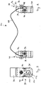
- a finishing belt 18 is provided, which is taken from a supply 20 and is supplied by means of a first guide device 22 to a first pressing device 24 and a deflection point 26. Starting from the deflection point 26, the finishing belt 18 is fed to a second pressure device 28 and a second guide device 30 and finally to a collector 32.
- the pressing devices 24 and 28 are held on opposite sides of the workpiece 12 respectively on pivot arms 34, 36, which are pivotable about respective support arm pivot axes 38, 40.
- the support arm pivot axes 38, 40 are stationary relative to a frame part 42.
- the frame part 42 also serves to arrange a drive device 44, which is known per se and is therefore only shown in sections.
- the drive device 44 serves to press the pincer-like holding arms 34, 36 in each case with the pressing device 24 or 28 held thereon in the direction of the workpiece 12.
- the workpiece 12 In the course of machining the workpiece 12 this rotates around the Rotation axis 14.
- the finishing belt 18 is pressed at the level of the pressing devices 24, 28 against the workpiece surface 16 to be machined.
- the rotational movement of the workpiece 12 is superimposed on the rotational axis 14 by an oscillating linear movement.
- the workpiece 12 oscillates along the axis of rotation 14 relative to the finishing belt 18. It is possible, the workpiece 12 and / or the finishing belt 18 to drive oscillating. This oscillation movement produces a cross-cut structure characteristic of a finishing process.
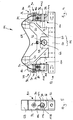
- the structure of the pressing means 24, 28 and their connection to the holding arms 34, 36 will be described below with reference to FIG. 2 explained.
- the holding arms 34, 36 have free ends 46, 48, to each of which a base support 50 of a pressing device 24, 28 is fastened by means of a screw 51.
- the base support 50 has a base 52 and protruding from the base 52 arms 54 and 56. Between the arms 54 and 56 is formed along the base 52 extending free space, which serves for the arrangement of a bearing block 58.
- the bearing block 58 is used for pivotal mounting of a V-shaped additional element 60. Accordingly, the additional element 60 is pivotally mounted about an additional element pivot axis 62 on the base support 50 of the pressing device 24, 28.
- the V-shaped additional element 60 has in each case at its free ends rounded support points 64, 66, which serve to support the back of a Andschreibbands 68.
- the pressure belt 68 is slidably mounted in the region of the support points 64, 66.
- the pressing belt 68 transmits with its front side a pressing force on the back side of the finishing belt 18, so that its front side is pressed against the workpiece surface 16 of the workpiece 12.
- the pivotable mounting of the additional element 60 makes it possible for different sized workpieces 12 (see. Figures 2 and 3 ) to compensate for different opening angles of the holding arms 34, 36, so that a finishing effective portion 70 of the finishing belt 18 respectively is aligned centrally between the support points 64, 66. This is also possible because the additional element pivot axis 62 extends parallel to the axis of rotation 14 of the workpiece 12.
- a pivot pin 72 is provided for pivotal mounting of the additional part 60 to the base support 50.
- the pivot pin 72 cooperates with a locking screw 74, which fixes the additional part 60 to the pivot pin 72.
- the additional element 60, the pivot pin 72 and the locking screw 74 form a pivoting group, which is pivoted together about the additional element pivot axis 62.
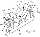
- two fixing devices 78, 80 are provided, which are preferably constructed identically and each serve to fix a Andschreibbandende 82, 84 of the Andschreibbands 68.
- the fixing devices 78, 80 are designed as clamping devices and each have a clamping slot 86 for receiving a Andschreibbandendes 82 and 84 on.
- the Andschreibbandenden 82, 84 have a hole 88 for the passage of a clamping screw 90.
- the clamping screw 90 serves to move on both sides of the clamping slot 86 material portions 92 and 94 of a fixing device 78, 80 zuzubewegen to narrow the clamping slot 86, so that each of the Andschreibbandende 82 and 84 facing surfaces of the material portions 92, 94 form clamping surfaces.
- delimiting the clamping slot 86 in the lateral direction delimiting elements 96 are provided, which are screwed, for example, with the material portion 94.
- the material sections 92 and 94 are integrally formed with a further material section 98 of a fixing device 78, 80.
- the connector 100 includes a plug in the form of a bearing pin 102, which is preferably arranged on each one of the arms 54, 56 of the Andschreibbandanys 76.
- the bearing pin 102 cooperates with a connector receptacle in the form of a bearing pin receptacle 104. This is formed by the material section 98 of the fixing device 78, 80.
- the bearing pin 102 and the bearing pin receptacle 104 together form a pivot bearing 106 with an axis 108 which is orthogonal to the axis of rotation 14 of the workpiece 12.
- Andrückbands 68 on the Andschreibbandzi 76 is a preformed Andschreibband (see. FIGS. 6 and 7 ) are first connected to two fixing devices 78, 80 by the Andschreibbandenden 82 and 84 are each clamped in a clamping slot 86 of the fixing means 78, 80.
- a mounting group 110 consisting of a pressing belt 68 and two fixing devices 78, 80, compare FIG. 8 ,
- bearing pin receptacle 104 are hollow cylindrical and the bearing pin 102 are cylindrical in order to jointly form a plug connection 100.
- a bearing pin receiving surface 112 of the bearing pin receptacle 104 seen in the circumferential direction has an opening 114 (see. FIG. 9 ).
- This opening 114 serves to be able to introduce the bearing pin 102 in the lateral direction in the bearing pin receptacle 104.
- the bearing pin 102 along a circumference of its bearing pin surface 116 with respect to a cylindrical shape a taper 118, see FIGS. 10 to 12 ,
- the assembly 110 is positioned relative to the Andschreibbandany 76 that a first fixing device 80 can be joined with its bearing pin receptacle 104 with a first bearing pin 102.
- the opening 114 of the bearing pin receptacle 104 of the first fixing device 80 is aligned so that it can be plugged onto the taper 118 of a first bearing pin 102.
- the first fixing device 80 is releasably secured to the Andschreibbandany 76, see FIGS. 10 and 11 ,
- the second fixing device 78 can then be joined to the Andschreibbandani 76 by the mounting assembly 110 is pivoted by 180 ° about the pivot axis 108 of the first fixing device 80 (see. Figures 11 and 12 ). In this way, the opening 114 of the bearing pin receptacle 104 of the second fixing device 78 can be brought in the joining position with the second bearing pin 102 of the Andschreibbandanys 76 (see. FIG. 12 ). On this basis, the second bearing pin 102 and the bearing pin receptacle 104 of the second fixing device 78 can be joined together, as indicated by a dashed arrow in FIG FIG. 12 is indicated.
- the pressure belt 68 is based on its power-free output form (see 6 and 7 ) deformed, in particular bent and / or twisted. This is an elastic deformation.
Landscapes
- Engineering & Computer Science (AREA)
- Mechanical Engineering (AREA)
- Finish Polishing, Edge Sharpening, And Grinding By Specific Grinding Devices (AREA)
- Constituent Portions Of Griding Lathes, Driving, Sensing And Control (AREA)
- Automatic Assembly (AREA)
- Folding Of Thin Sheet-Like Materials, Special Discharging Devices, And Others (AREA)
- Treatment Of Fiber Materials (AREA)
Description
Die Erfindung betrifft eine Andrückeinrichtung zum Andrücken eines Finishbands gegen eine Werkstückoberfläche, umfassend ein Andrückband und einen Andrückbandträger, der das Andrückband an zwei zueinander beabstandeten Stützstellen abstützt, wobei das Andrückband lösbar an dem Andrückbandträger befestigt ist.The invention relates to a pressing device for pressing a finishing strip against a workpiece surface, comprising a pressure belt and a Andrückbandträger, which supports the pressure belt at two spaced support points, wherein the pressure belt is releasably secured to the Andrückbandträger.
Aus der
Es hat sich herausgestellt, dass bei den bekannten Andrückeinrichtungen eine exakte Ausrichtung eines Andrückbands an dem Andrückbandträger und ein bei einer Beschädigung eines Andrückbands erforderlicher Austausch des beschädigten Andrückbands gegen ein neues Andrückband einen hohen Zeitaufwand erfordern. Hierdurch bedingt verlängern sich die vor oder während der Bearbeitung eines Werkstückloses benötigten Nebenzeiten einer Vorrichtung zur finishenden Bearbeitung eines Werkstücks.It has been found that in the known pressure devices exact alignment of a Andrückbands on the Andrückbandträger and in case of damage of a Andrückbands required replacement of the damaged Andrückbands against a new Andrückband require a lot of time. As a result of this, the non-productive times required before or during the machining of a workpiece lot are lengthened by a device for finish-machining a workpiece.
Hiervon ausgehend liegt der vorliegenden Erfindung die Aufgabe zugrunde, eine Andrückeinrichtung bereitzustellen, mit welcher die Nebenzeiten einer Vorrichtung zur finishenden Bearbeitung eines Werkstücks verkürzt werden können.Proceeding from this, the present invention has the object to provide a pressing device with which the non-productive times of a device for finishing machining a workpiece can be shortened.
Diese Aufgabe wird erfindungsgemäß dadurch gelöst, dass zur Fixierung jeweils eines Andrückbandendes eine von dem Andrückbandträger separat bereitgestellte Fixiereinrichtung vorgesehen ist und dass die Fixiereinrichtung in einem Zustand, in welchem ein Andrückbandende an der Fixiereinrichtung fixiert ist, lösbar an dem Andrückbandträger befestigbar oder befestigt ist.This object is achieved in that for fixing a respective Andrückbandendes provided by the Andrückbandträger separately fixing is provided and that the Fixing device in a state in which a Andrückbandende is fixed to the fixing device, releasably attachable to the Andrückbandträger is fixed.
Erfindungsgemäß ist es möglich, die Handhabung der Enden des Andrückbands räumlich von dem Andrückbandträger zu entkoppeln. Hierfür sind Fixiereinrichtungen vorgesehen, welche lösbar an dem Andrückband befestigbar oder befestigt sind, wobei diese Fixiereinrichtungen unabhängig von dem Andrückbandträger eine Fixierung der Andrückbandenden an der jeweiligen Fixiereinrichtung ermöglichen. Auf diese Weise ist es möglich, ein Andrückbandende mit einer Fixiereinrichtung zu verbinden, sodass das Andrückbandende in der Fixiereinrichtung fixiert ist, wobei dieser Vorgang räumlich außerhalb einer Vorrichtung zur finishenden Bearbeitung eines Werkstücks erfolgt, und wobei erst anschließend die Fixiereinrichtung an dem Andrückbandträger befestigt wird. Außerdem können Austauschandrückbänder, welche bereits an separaten Fixiereinrichtungen fixiert sind, bereitgehalten werden, um im Falle einer Beschädigung eines Andrückbands das beschädigte Andrückband samt Fixiereinrichtungen gegen ein neues Andrückband, welches bereits in zwei anderen Fixiereinrichtungen fixiert ist, auszutauschen.According to the invention, it is possible to decouple the handling of the ends of the Andrückbands spatially from the Andrückbandträger. For this purpose, fixing devices are provided, which can be fastened or fastened detachably to the pressure belt, wherein these fixing devices make it possible to fix the pressure belt ends to the respective fixing device independently of the pressure belt carrier. In this way it is possible to connect a Andrückbandende with a fixing device, so that the Andrückbandende is fixed in the fixing device, this process spatially outside a device for finishing machining of a workpiece, and only then the fixing is attached to the Andrückbandträger. In addition, Austauschandrückbänder, which are already fixed to separate fixing devices, are kept ready to replace in the event of damage to a Andrückbands the damaged Andrückband including fixing against a new Andrückband, which is already fixed in two other fixing devices.
Erfindungsgemäß werden also die zeitaufwändigen Einrichtvorgänge, die im Zusammenhang mit der Handhabung eines Andrückbands stehen, räumlich von dem Andrückbandträger einer Vorrichtung zur finishenden Bearbeitung eines Werkstücks entkoppelt, sodass die zeitaufwändigen Handhabungsvorgänge während des Betriebs der Finishvorrichtung, also während der Hauptzeiten der Finishvorrichtung, durchgeführt werden können. Die Nebenzeiten, die im Zusammenhang mit der Montage eines Andrückbandes stehen, werden somit auf eine Zeitdauer verkürzt, welche zur lösbaren Befestigung der Fixiereinrichtungen an dem Andrückbandträger und zum Lösen der Fixiereinrichtungen von dem Andrückbandträger erforderlich sind.Thus, according to the invention, the time-consuming set-up operations associated with the handling of a pressure belt are spatially decoupled from the pressure belt carrier of a finishing machining apparatus such that the time-consuming handling operations can be performed during operation of the finishing apparatus, ie during the main times of the finishing apparatus , The non-productive times, which are associated with the installation of a pressure band, are thus shortened to a period of time, which are required for releasably securing the fixing means on the Andrückbandträger and for releasing the fixing means of the Andrückbandträger.
Eine besonders zuverlässige Fixierung des Andrückbands an der Fixiereinrichtung ergibt sich, wenn die Fixiereinrichtung als Klemmeinrichtung ausgebildet ist. In einem fixierten Zustand des Andrückbands an der Fixiereinrichtung sind das fixierte Ende des Andrückbands und die Fixiereinrichtung nicht relativ zueinander bewegbar.A particularly reliable fixation of the Andrückbands on the fixing results when the fixing device as Clamping device is formed. In a fixed state of the Andrückbands to the fixing device, the fixed end of the Andrückbands and the fixing device are not movable relative to each other.
Eine besonders gute Fixierung des Andrückbands an der Fixiereinrichtung ergibt sich, wenn die Fixiereinrichtung einen von zwei Klemmflächen begrenzten Klemmschlitz zur Aufnahme eines Andrückbandendes aufweist.A particularly good fixation of the Andrückbands on the fixing device results when the fixing device has a clamping surface delimited by two clamping surfaces for receiving a Andrückbandendes.
Die Handhabung des Andrückbands bei der Montage eines Andrückbandendes an der Fixiereinrichtung wird weiter vereinfacht, wenn die Fixiereinrichtung Begrenzungselemente zur seitlichen Begrenzung des Klemmschlitzes aufweist.The handling of the Andrückbands in the installation of a Andrückbandendes to the fixing device is further simplified if the fixing device has limiting elements for laterally limiting the clamping slot.
Besonders bevorzugt ist es, dass zwei Fixiereinrichtungen gemeinsam mit dem Andrückband eine Montagegruppe bilden, welche als Ganzes an dem Andrückbandträger montierbar und von dem Andrückbandträger lösbar ist. Bei einer solchen Montagegruppe sind die jeweiligen Enden des Andrückbands an oder innerhalb einer jeweiligen Fixiereinrichtung fixiert, sodass in dem Verbindungsbereich zwischen Andrückbandende und Fixiereinrichtung keine Relativbewegung zwischen dem Andrückbandende und der Fixiereinrichtung möglich ist. Die Fixiereinrichtungen können dennoch relativ zueinander hinsichtlich ihrer Position und Lage verändert werden, nämlich indem das Andrückband elastisch verformt wird. Dies vereinfacht die Montage der Montagegruppe an dem Andrückbandträger und auch die Demontage der Montagegruppe von dem Andrückbandträger.It is particularly preferred that two fixing devices together with the pressure belt form a mounting group which can be mounted as a whole on the Andrückbandträger and detachable from the Andrückbandträger. In such an assembly group, the respective ends of the pressing belt are fixed to or within a respective fixing device, so that no relative movement between the pressing belt end and the fixing device is possible in the connecting region between the pressing belt end and the fixing device. The fixing devices can still be changed relative to each other in terms of their position and location, namely by the pressure band is elastically deformed. This simplifies the assembly of the assembly group on the Andrückbandträger and also the disassembly of the assembly of the Andrückbandträger.
Vorzugsweise ist zur lösbaren Verbindung der Fixiereinrichtung an dem Andrückbandträger eine Steckverbindung vorgesehen. Dies ermöglicht eine besonders schnelle und einfache Montage einer Fixiereinrichtung an dem Andrückbandträger.Preferably, a plug connection is provided for the detachable connection of the fixing device to the Andrückbandträger. This allows a particularly quick and easy installation of a fixing device on the Andrückbandträger.
Die Steckverbindung umfasst vorzugsweise einen Stecker in Form eines Lagerbolzens und eine Steckeraufnahme in Form einer Lagerbolzenaufnahme. Hierdurch kann eine einfach aufgebaute und stabile Steckverbindung bereitgehalten werden.The plug connection preferably comprises a plug in the form of a bearing pin and a plug receptacle in the form of a bearing pin receptacle. As a result, a simple structure and stable connector can be kept.
Besonders bevorzugt ist es, wenn der Lagerbolzen und die Lagerbolzenaufnahme ein Schwenklager bilden. Auf diese Weise erfüllen die Verbindungsabschnitte zur Verbindung der Fixiereinrichtung und des Andrückbandträgers eine Zusatzfunktion, welche es ermöglicht, eine Fixiereinrichtung schwenkbar an dem Andrückbandträger zu lagern. Eine solche Verschwenkbarkeit hat den Vorteil, dass ein Andrückband zumindest weitestgehend spannungsfrei an dem Andrückbandträger anordenbar ist.It is particularly preferred if the bearing pin and the Make bearing pin receptacle a pivot bearing. In this way, the connecting portions for connecting the fixing device and the Andrückbandträgers fulfill an additional function, which makes it possible to pivotally mount a fixing device on the Andrückbandträger. Such a pivotability has the advantage that a pressure band is at least largely tension-free on the Andrückbandträger can be arranged.
Besonders bevorzugt ist es, wenn die Achse des Schwenklagers senkrecht zu einer Rotationsachse eines zu bearbeitenden Werkstücks verläuft. Auf diese Weise ist gewährleistet, dass sich das Andrückband und ein mittels des Andrückbands gegen eine zu bearbeitende Werkstückoberfläche druckbeaufschlagtes Finishband exakt relativ zu der zu bearbeitenden Werkstückoberfläche ausrichten können, ohne dass während der Bearbeitung einer Werkstückoberfläche Spannungen innerhalb des Andrückbands auftreten. Auf diese Weise wird die während der finishenden Bearbeitung eines Werkstücks zu erreichende Oberflächengüte verbessert. Ferner wird die Betriebsdauer eines Andrückbands verlängert.It is particularly preferred if the axis of the pivot bearing extends perpendicular to a rotational axis of a workpiece to be machined. In this way it is ensured that the pressure belt and a pressure belt, which is pressurized by means of the pressure belt against a workpiece surface to be machined, can exactly align relative to the workpiece surface to be machined without stresses occurring within the pressure belt during the processing of a workpiece surface. In this way, the surface finish to be achieved during finishing machining of a workpiece is improved. Furthermore, the service life of a Andrückbands is extended.
Eine besonders einfach aufgebaute Andrückeinrichtung ergibt sich, wenn der Lagerbolzen an dem Andrückbandträger ausgebildet ist und wenn die Lagerbolzenaufnahme an der Fixiereinrichtung ausgebildet ist.A particularly simple constructed pressing device is obtained when the bearing pin is formed on the Andrückbandträger and when the bearing pin receptacle is formed on the fixing device.
Um eine besonders einfache Montage einer Fixiereinrichtung an dem Andrückbandträger zu ermöglichen, wird vorgeschlagen, dass die Lagerbolzenaufnahme entlang eines Umfangs ihrer Lagerbolzenaufnahmefläche eine Durchbrechung aufweist, dass der Lagerbolzen entlang eines Umfangs seiner Lagerbolzenfläche bezogen auf eine Zylinderform eine Verjüngung aufweist und dass die Verjüngung und die Durchbrechung miteinander fügbar sind. Dies ermöglicht es, die Fixiereinrichtung und den Andrückbandträger in zu einer Steckachse seitlicher Richtung miteinander zu fügen. Auf diese Weise kann das Maß einer elastischen Verformung eines Andrückbands im Zuge der Montage und Demontage der Fixiereinrichtungen an dem Andrückbandträger reduziert werden.In order to enable a particularly simple mounting of a fixing device on the Andrückbandträger, it is proposed that the bearing pin receptacle along a circumference of their bearing pin receiving surface has an opening that the bearing pin along a circumference of its bearing pin surface with respect to a cylindrical shape has a taper and that the taper and the opening are mutually available. This makes it possible to join the fixing device and the Andrückbandträger in to a thru-axle lateral direction with each other. In this way, the degree of elastic deformation of a Andrückbands can be reduced in the course of assembly and disassembly of the fixing means on the Andrückbandträger.
Es ist möglich, dass der Andrückbandträger einteilig ausgebildet ist. Bei einer bevorzugten Ausführungsform ist jedoch vorgesehen, dass der Andrückbandträger mehrteilig ist und einen Grundträger zur lösbaren Befestigung der Fixiereinrichtungen umfasst sowie ein an dem Grundträger bewegbar gelagertes Zusatzelement, mittels welchem die Stützstellen bereitgestellt sind. Auf diese Weise wird ein weiterer Freiheitsgrad geschaffen, welcher eine spannungsfreie Anordnung des Andrückbands an dem Andrückbandträger ermöglicht.It is possible that the Andrückbandträger is integrally formed. In a preferred embodiment, however, it is provided that the Andrückbandträger is multi-part and comprises a base support for releasably securing the fixing means and a movably mounted on the base support additional element, by means of which the support points are provided. In this way, a further degree of freedom is created, which allows a tension-free arrangement of the Andrückbands on the Andrückbandträger.
Besonders bevorzugt ist es, dass das Zusatzelement um eine Zusatzelementschwenkachse schwenkbar an dem Grundträger gelagert ist. Auf diese Weise können die Stützstellen relativ zu dem Grundträger verschwenkt werden.It is particularly preferred that the additional element is mounted pivotably about an additional element pivot axis on the base support. In this way, the support points can be pivoted relative to the base support.
Insbesondere ist es bevorzugt, dass die Zusatzelementschwenkachse parallel zu einer Rotationsachse eines zu bearbeitenden Werkstücks verläuft. Dies ermöglicht es, mittels derselben Andrückeinrichtung Werkstücke mit unterschiedlichen Durchmessern bearbeiten zu können, wobei sich das Zusatzelement um die Zusatzelementschwenkachse in Abhängigkeit des Durchmessers eines zu bearbeitenden Werkstücks an dem Grundträger ausrichtet.In particular, it is preferred that the additional element pivot axis runs parallel to a rotation axis of a workpiece to be machined. This makes it possible to work by means of the same pressing device workpieces with different diameters, with the additional element to the Zusatzelementschwenkachse depending on the diameter of a workpiece to be machined on the base carrier aligns.
Weitere Merkmale und Vorteile der Erfindung sind Gegenstand der nachfolgenden Beschreibung und der zeichnerischen Darstellung eines bevorzugten Ausführungsbeispiels.
-
Fig. 1 eine Seitenansicht einer Ausführungsform einer Vorrichtung zur finishenden Bearbeitung eines Werkstücks, mit zwei Andrückeinrichtungen; -
Fig. 2 die Andrückeinrichtungen gemäßFig. 1 bei Finishbearbeitung eines Werkstücks mit kleinerem Durchmesser; -
Fig. 3 eine derFig. 2 entsprechende Ansicht bei Finishbearbeitung eines Werkstücks mit größerem Durchmesser; -
Fig. 4 eine Seitenansicht einer Ausführungsform einer Andrückeinrichtung; -
Fig. 5 eine Vorderansicht der Andrückeinrichtung gemäßFig. 4 ; -
Fig. 6 eine Seitenansicht einer Ausführungsform eines Andrückbands; -
Fig. 7 eine Vorderansicht des Andrückbands gemäßFig. 6 ; -
Fig. 8 eine Seitenansicht einer Ausführungsform einer Montagegruppe der Andrückeinrichtung; -
Fig. 9 eine Vorderansicht der Montagegruppe gemäßFig. 8 ; -
Fig. 10 eine perspektivische Ansicht der Andrückeinrichtung gemäßFig. 4 und 5 , wobei die Montagegruppe gemäßFig. 8 und 9 in einem ersten Montagezustand dargestellt ist; -
Fig. 11 eine derFig. 10 entsprechende Ansicht, wobei die Montagegruppe in einem zweiten Montagezustand dargestellt ist; und -
Fig. 12 eine derFig. 10 entsprechende Ansicht, wobei die Montagegruppe in einem dritten Montagezustand dargestellt ist.
-
Fig. 1 a side view of an embodiment of a device for finish machining a workpiece, with two pressing devices; -
Fig. 2 the pressing devices according toFig. 1 during finish machining of a smaller diameter workpiece; -
Fig. 3 one of theFig. 2 corresponding view when finishing a workpiece with a larger diameter; -
Fig. 4 a side view of an embodiment of a pressing device; -
Fig. 5 a front view of the pressing device according toFig. 4 ; -
Fig. 6 a side view of an embodiment of a Andrückbands; -
Fig. 7 a front view of the Andrückbands according toFig. 6 ; -
Fig. 8 a side view of an embodiment of a mounting group of the pressing device; -
Fig. 9 a front view of the assembly group according toFig. 8 ; -
Fig. 10 a perspective view of the pressing device according to4 and 5 , wherein the assembly group according to8 and 9 is shown in a first mounting state; -
Fig. 11 one of theFig. 10 corresponding view, wherein the assembly group is shown in a second mounting state; and -
Fig. 12 one of theFig. 10 corresponding view, wherein the mounting group is shown in a third mounting state.
Zur Bearbeitung der Oberfläche 16 ist ein Finishband 18 vorgesehen, welches einem Vorrat 20 entnommen wird und mittels einer ersten Führungseinrichtung 22 einer ersten Andrückeinrichtung 24 und einer Umlenkstelle 26 zugeführt wird. Von der Umlenkstelle 26 ausgehend wird das Finishband 18 einer zweiten Andrückeinrichtung 28 und einer zweiten Führungseinrichtung 30 und schließlich einem Sammler 32 zugeführt.For machining the
Die Andrückeinrichtungen 24 und 28 sind auf einander gegenüberliegenden Seiten des Werkstücks 12 jeweils an Schwenkarmen 34, 36 gehalten, welche um jeweilige Haltearm-Schwenkachsen 38, 40 verschwenkbar sind. Die Haltearm-Schwenkachsen 38, 40 sind bezogen auf ein Gestellteil 42 ortsfest. Das Gestellteil 42 dient auch zur Anordnung einer Antriebseinrichtung 44, welche an sich bekannt ist und daher nur abschnittsweise dargestellt ist. Die Antriebseinrichtung 44 dient dazu, die zangenartigen Haltearme 34, 36 jeweils mit daran gehaltener Andrückeinrichtung 24 bzw. 28 in Richtung auf das Werkstück 12 zu drücken.The
Im Zuge der Bearbeitung des Werkstücks 12 rotiert dieses um die Rotationsachse 14. Das Finishband 18 wird jeweils auf Höhe der Andrückeinrichtungen 24, 28 gegen die zu bearbeitende Werkstückoberfläche 16 gedrückt. Gleichzeitig wird der Rotationsbewegung des Werkstücks 12 um die Rotationsachse 14 eine oszilierende Linearbewegung überlagert. Hierbei oszilliert das Werkstück 12 entlang der Rotationsachse 14 relativ zu dem Finishband 18. Dabei ist es möglich, das Werkstück 12 und/oder das Finishband 18 oszillierend anzutreiben. Durch diese Oszillationsbewegung wird eine für ein Finishverfahren charakteristische Kreuzschliffstruktur erzeugt.In the course of machining the
Der Aufbau der Andrückeinrichtungen 24, 28 sowie deren Verbindung zu den Haltearmen 34, 36 wird nachfolgend unter Bezugnahme auf
Der Grundträger 50 weist eine Basis 52 auf und von der Basis 52 abragende Arme 54 und 56. Zwischen den Armen 54 und 56 ist ein sich entlang der Basis 52 erstreckender Freiraum ausgebildet, welcher zur Anordnung eines Lagerbocks 58 dient.The
Der Lagerbock 58 dient zur Schwenklagerung eines V-förmigen Zusatzelements 60. Demnach ist das Zusatzelement 60 um eine Zusatzelementschwenkachse 62 schwenkbar an dem Grundträger 50 der Andrückeinrichtung 24, 28 gelagert.The bearing
Das V-förmige Zusatzelement 60 weist jeweils an seinen freien Enden abgerundete Stützstellen 64, 66 auf, welche dazu dienen, die Rückseite eines Andrückbands 68 abzustützen. Das Andrückband 68 ist im Bereich der Stützstellen 64, 66 gleitend gelagert.The V-shaped
Das Andrückband 68 überträgt mit seiner Vorderseite eine Andrückkraft auf die Rückseite des Finishbands 18, sodass dessen Vorderseite gegen die Werkstückoberfläche 16 des Werkstücks 12 angedrückt wird.The
Die schwenkbare Lagerung des Zusatzelements 60 ermöglicht es, für unterschiedlich große Werkstücke 12 (vgl.
Nachfolgend wird der Aufbau einer Andrückeinrichtung 24, 28 am Beispiel der Andrückeinrichtung 24 und unter Bezugnahme auf die
Zur Schwenklagerung des Zusatzteils 60 an dem Grundträger 50 ist ein Schwenkbolzen 72 vorgesehen. Der Schwenkbolzen 72 wirkt mit einer Sicherungsschraube 74 zusammen, welche das Zusatzteil 60 an dem Schwenkbolzen 72 fixiert. Somit bilden das Zusatzelement 60, der Schwenkbolzen 72 und die Sicherungsschraube 74 eine Schwenkgruppe, welche gemeinsam um die Zusatzelementschwenkachse 62 verschwenkbar ist.For pivotal mounting of the
Das Zusatzelement 60 und der Grundträger 50 bilden gemeinsam einen Andrückbandträger 76.The
Zur Fixierung des Andrückbandes 68 an dem Andrückbandträger 76 sind zwei Fixiereinrichtungen 78, 80 vorgesehen, welche vorzugsweise identisch aufgebaut sind und jeweils dazu dienen, ein Andrückbandende 82, 84 des Andrückbands 68 zu fixieren.For fixing the
Die Fixiereinrichtungen 78, 80 sind als Klemmeinrichtungen ausgebildet und weisen jeweils einen Klemmschlitz 86 zur Aufnahme eines Andrückbandendes 82 bzw. 84 auf. Die Andrückbandenden 82, 84 weisen ein Loch 88 zum Durchtritt einer Klemmschraube 90 auf. Die Klemmschraube 90 dient dazu, beidseits des Klemmschlitzes 86 angeordnete Materialabschnitte 92 und 94 einer Fixiereinrichtung 78, 80 zur Verengung des Klemmschlitzes 86 aufeinander zuzubewegen, sodass die jeweils dem Andrückbandende 82 bzw. 84 zugewandten Flächen der Materialabschnitte 92, 94 Klemmflächen bilden.The fixing
Zur Begrenzung des Klemmschlitzes 86 in seitlicher Richtung sind Begrenzungselemente 96 vorgesehen, welche beispielsweise mit dem Materialabschnitt 94 verschraubt sind.For limiting the clamping
Die Materialabschnitte 92 und 94 sind einstückig mit einem weiteren Materialabschnitt 98 einer Fixiereinrichtung 78, 80 ausgebildet.The
Während die Materialabschnitte 92 und 94 zur Fixierung eines Andrückbandendes 82, 84 dienen, wird der Materialabschnitt 98 vorgehalten, um eine nachfolgend beschriebene, lösbare Verbindung mit dem Andrückbandträger 76 zu ermöglichen.While the
Insbesondere ist die lösbare Verbindung zwischen einer Fixiereinrichtung 78 und 80 und dem Andrückbandträger 76 in Form einer Steckverbindung 100 ausgebildet. Die Steckverbindung 100 umfasst einen Stecker in Form eines Lagerbolzens 102, welcher vorzugsweise an jeweils einem der Arme 54, 56 des Andrückbandträgers 76 angeordnet ist. Der Lagerbolzen 102 wirkt mit einer Steckeraufnahme in Form einer Lagerbolzenaufnahme 104 zusammen. Diese wird durch den Materialabschnitt 98 der Fixiereinrichtung 78, 80 gebildet. Der Lagerbolzen 102 und die Lagerbolzenaufnahme 104 bilden gemeinsam ein Schwenklager 106 mit einer Achse 108, welche orthogonal zu der Rotationsachse 14 des Werkstücks 12 verläuft.In particular, the detachable connection between a fixing
Zur Montage des Andrückbands 68 an dem Andrückbandträger 76 wird ein vorgeformtes Andrückband (vgl.
Es ist möglich, dass die Lagerbolzenaufnahme 104 hohlzylindrisch und der Lagerbolzen 102 zylindrisch ausgebildet sind, um gemeinsam eine Steckverbindung 100 zu bilden.It is possible that the bearing
Bei einer bevorzugten Ausführungsform ist jedoch vorgesehen, dass eine Lagerbolzenaufnahmefläche 112 der Lagerbolzenaufnahme 104 in Umfangsrichtung gesehen eine Durchbrechung 114 aufweist (vgl.
Zur lösbaren Befestigung der Montagegruppe 110 an dem Andrückbandträger 76 wird die Baugruppe 110 so relativ zu dem Andrückbandträger 76 positioniert, dass eine erste Fixiereinrichtung 80 mit ihrer Lagerbolzenaufnahme 104 mit einem ersten Lagerbolzen 102 gefügt werden kann. Hierfür wird die Durchbrechung 114 der Lagerbolzenaufnahme 104 der ersten Fixiereinrichtung 80 so ausgerichtet, dass diese auf die Verjüngung 118 eines ersten Lagerbolzens 102 aufgesteckt werden kann. Auf diese Weise wird die erste Fixiereinrichtung 80 lösbar an dem Andrückbandträger 76 befestigt, vergleiche
Die zweite Fixiereinrichtung 78 kann anschließend mit dem Andrückbandträger 76 gefügt werden, indem die Montagegruppe 110 um 180° um die Schwenkachse 108 der ersten Fixiereinrichtung 80 verschwenkt wird (vgl.
Ausgehend von einem Zustand, in welchem die Fixiereinrichtungen 78 und 80 jeweils lösbar an dem Andrückbandträger 76 befestigt sind, und in welchem die Lagerbolzen 102 in den jeweiligen Lagerbolzenaufnahmen 104 aufgenommen sind, kann die Montagegruppe 110 zum Abschluss der Montage um 90° um die Achse 108 verschwenkt werden, wie dies mit einem gestrichelten Schwenkpfeil in
Im Zuge der Verschwenkung des Andrückbands 68 ausgehend aus der in
Während der Montage der Fixiereinrichtungen 78, 80 an dem Andrückbandträger 76 wird das Andrückband 68 ausgehend von seiner kraftfreien Ausgangsform (vergleiche
Claims (14)
- Pressing device (24) for pressing a finishing belt (18) against a workpiece surface (16), comprising a pressure belt (68) and a pressure belt carrier (76) that supports the pressure belt (68) at two spaced-apart support points (64, 66), the pressure belt (68) being releasably fastened to the pressure belt carrier (76), characterized in that to secure the pressure belt ends (82, 84), a securing device (78, 80), provided separately from the pressure belt carrier (76), is provided for each pressure belt end and in that, when in a state in which a pressure belt end (82, 84) is secured to the securing device (78, 80), the securing device (78, 80) is or can be releasably fastened to the pressure belt carrier (76).
- Pressing device (24) according to claim 1, characterized in that the securing device (78, 80) is designed as a clamping device.
- Pressing device (24) according to any of the preceding claims, characterized in that the securing device (78, 80) comprises a clamping slot (86), delimited by two clamping surfaces, for receiving a pressure belt end (82, 84).
- Pressing device (24) according to claim 3, characterized in that the securing device (78, 80) comprises delimiting elements (96) for laterally delimiting the clamping slot (86).
- Pressing device (24) according to any of the preceding claims, characterized in that, together with the pressure belt (68), two securing devices (78, 80) form a fitting unit (110) that can be fitted as a whole on the pressure belt carrier (76) and is releasable from the pressure belt carrier (76).
- Pressing device (24) according to any of the preceding claims, characterized in that a plug-in connection (100) is provided for releasably connecting the securing device (78, 80) to the pressure belt carrier (76).
- Pressing device (24) according to claim 6, characterized in that the plug-in connection (100) comprises a plug in the form of a bearing pin (102) and a socket in the form of a bearing pin receptacle (104).
- Pressing device (24) according to claim 7, characterized in that the bearing pin (102) and the bearing pin receptacle (104) form a pivot bearing (106).
- Pressing device (24) according to claim 8, characterized in that the axis (108) of the pivot bearing (106) extends perpendicularly to an axis of rotation (14) of a workpiece (12) to be machined.
- Pressing device (24) according to any of claims 7 to 9, characterized in that the bearing pin (102) is formed on the pressure belt carrier (76) and in that the bearing pin receptacle (104) is formed on the securing device (78, 80).
- Pressing device (24) according to any of claims 7 to 10, characterized in that the bearing pin receptacle (104) comprises an opening (114) along a periphery of its bearing pin receptacle surface (112), in that the bearing pin (102) has a taper (118), based on a cylinder shape, along a periphery of its bearing pin surface (116) and in that the taper (118) and the opening (114) can be joined together.
- Pressing device (24) according to any of the preceding claims, characterized in that the pressure belt carrier (76) is in multiple parts and comprises a main carrier (50) for releasably fastening the securing device (78, 80) and an additional element (60) that is movably mounted on the main carrier (50) and by means of which the support points (64, 66) are provided.
- Pressing device (24) according to claim 12, characterized in that the additional element (60) is mounted on the main carrier (50) so as to be pivotable about an additional-element pivot axis (62).
- Pressing device (24) according to claim 13, characterized in that the additional-element pivot axis (62) extends in parallel with an axis of rotation (14) of a workpiece (12) to be machined.
Applications Claiming Priority (2)
| Application Number | Priority Date | Filing Date | Title |
|---|---|---|---|
| DE102014213194.4A DE102014213194A1 (en) | 2014-07-08 | 2014-07-08 | Pressing device for pressing a Finisbands against a workpiece surface |
| PCT/EP2015/064372 WO2016005193A1 (en) | 2014-07-08 | 2015-06-25 | Pressing device for pressing a finishing belt against a workpiece surface |
Publications (2)
| Publication Number | Publication Date |
|---|---|
| EP3166751A1 EP3166751A1 (en) | 2017-05-17 |
| EP3166751B1 true EP3166751B1 (en) | 2018-03-28 |
Family
ID=53498988
Family Applications (1)
| Application Number | Title | Priority Date | Filing Date |
|---|---|---|---|
| EP15733407.9A Active EP3166751B1 (en) | 2014-07-08 | 2015-06-25 | Pressing device to press a finishing tape against the surface of a workpiece |
Country Status (6)
| Country | Link |
|---|---|
| US (1) | US9744639B2 (en) |
| EP (1) | EP3166751B1 (en) |
| KR (1) | KR101752148B1 (en) |
| CN (1) | CN106457505B (en) |
| DE (1) | DE102014213194A1 (en) |
| WO (1) | WO2016005193A1 (en) |
Families Citing this family (8)
| Publication number | Priority date | Publication date | Assignee | Title |
|---|---|---|---|---|
| DE102015216357A1 (en) | 2015-08-27 | 2017-03-02 | Supfina Grieshaber Gmbh & Co. Kg | Peripheral surface processing unit, machine tool and method of operation |
| DE102016107965A1 (en) | 2016-04-29 | 2017-11-02 | Supfina Grieshaber Gmbh & Co. Kg | Belt finishing device |
| DE102016116325A1 (en) | 2016-09-01 | 2018-03-01 | Supfina Grieshaber Gmbh & Co. Kg | Device, system and method for aligning at least one finishing or pressing tool held on a pincer-type pressing arm of a finish-machining unit |
| DE102017201120B3 (en) | 2017-01-24 | 2018-06-21 | Nagel Maschinen- Und Werkzeugfabrik Gmbh | Pressure device for finishing belt and belt finishing device |
| DE102017108191A1 (en) | 2017-04-18 | 2018-10-18 | Rud. Starcke Gmbh & Co. Kg | Method for partially grinding a surface and grinding device |
| CN112247772B (en) * | 2020-10-21 | 2021-10-22 | 佛山市维通金属制品有限公司 | Portable even grinding device of nonrust steel pipe welding seam |
| DE102022212676A1 (en) * | 2022-11-28 | 2024-05-29 | Nagel Maschinen- und Werkzeugfabrik Gesellschaft mit beschränkter Haftung. | Finishing process, finishing machine and finishing head |
| CN116944996B (en) * | 2023-09-19 | 2023-11-24 | 江苏诚品环保科技有限公司 | Multilayer wood floor polishing burring equipment |
Family Cites Families (11)
| Publication number | Priority date | Publication date | Assignee | Title |
|---|---|---|---|---|
| US3566549A (en) * | 1969-01-21 | 1971-03-02 | James A Britton | Flexible all purpose drill attachment |
| US4682444A (en) * | 1984-05-07 | 1987-07-28 | Industrial Metal Products Corporation | Microfinishing apparatus and method |
| DE4444239C3 (en) * | 1994-12-13 | 2003-05-08 | Supfina Grieshaber Gmbh & Co | finishing machine |
| JP3661712B2 (en) * | 1995-11-13 | 2005-06-22 | トヨタ自動車株式会社 | Lapping machine |
| DE19921043C2 (en) | 1999-05-07 | 2002-09-19 | Juergen Heesemann | belt sander |
| JP4156200B2 (en) * | 2001-01-09 | 2008-09-24 | 株式会社荏原製作所 | Polishing apparatus and polishing method |
| DE10332605B4 (en) * | 2003-07-17 | 2005-09-15 | Ibz Gmbh | Pressing device for a surface treatment device |
| DE10342139B4 (en) * | 2003-09-12 | 2008-06-19 | Thielenhaus Technologies Gmbh | Process for finishing peripheral surfaces on wave-shaped workpieces |
| DE102007051047B4 (en) | 2007-10-16 | 2023-03-23 | Nagel Maschinen- Und Werkzeugfabrik Gmbh | Press-on device for finishing belt and device and method for finishing peripheral surfaces on cylindrical workpiece sections |
| DE202013005504U1 (en) | 2013-06-12 | 2013-06-26 | Nagel Maschinen- Und Werkzeugfabrik Gmbh | Pressing device for finishing belt and device for finishing peripheral surfaces on cylindrical workpiece sections |
| DE202014000094U1 (en) * | 2014-01-13 | 2014-02-18 | Supfina Grieshaber Gmbh & Co. Kg | pressing device |
-
2014
- 2014-07-08 DE DE102014213194.4A patent/DE102014213194A1/en not_active Withdrawn
-
2015
- 2015-06-25 WO PCT/EP2015/064372 patent/WO2016005193A1/en not_active Ceased
- 2015-06-25 CN CN201580029217.8A patent/CN106457505B/en active Active
- 2015-06-25 KR KR1020177003204A patent/KR101752148B1/en active Active
- 2015-06-25 EP EP15733407.9A patent/EP3166751B1/en active Active
- 2015-06-25 US US15/319,804 patent/US9744639B2/en active Active
Also Published As
| Publication number | Publication date |
|---|---|
| EP3166751A1 (en) | 2017-05-17 |
| WO2016005193A1 (en) | 2016-01-14 |
| DE102014213194A1 (en) | 2016-01-28 |
| CN106457505B (en) | 2018-06-12 |
| US20170151645A1 (en) | 2017-06-01 |
| CN106457505A (en) | 2017-02-22 |
| KR101752148B1 (en) | 2017-07-11 |
| US9744639B2 (en) | 2017-08-29 |
| KR20170020534A (en) | 2017-02-22 |
Similar Documents
| Publication | Publication Date | Title |
|---|---|---|
| EP3166751B1 (en) | Pressing device to press a finishing tape against the surface of a workpiece | |
| DE69301352T2 (en) | Device for tensioning and holding glass panes to be shaped in their position during processing | |
| EP0999911A1 (en) | Device for separating the rod and cap of a connecting rod by breaking | |
| DE112015001669T5 (en) | jig | |
| DE112013000583B4 (en) | Saw blade clamping device | |
| DE2630498C3 (en) | Adjustable holder | |
| EP1977124B1 (en) | Device for holding and positioning implements, workpieces and tools | |
| EP3172012B1 (en) | Finishing device | |
| DE102012108031A1 (en) | Holder for a joining device | |
| EP2097199B1 (en) | System pendulum apparatus and method | |
| DE2851308C2 (en) | Device for mortising bearing bushes | |
| EP1743743B1 (en) | Spreader | |
| EP2995417B1 (en) | Device for mounting at least one functional element with a recess for a shaft | |
| DE2905689C2 (en) | ||
| DE10203389A1 (en) | jig | |
| DE102021120815B4 (en) | METHOD AND SELF-CENTERING FIXING DEVICE FOR FIXING A WELDING DEVICE TO A PIPE SECTION | |
| DE102016205658B3 (en) | CUTTING TOOL WITH A CUTTING BODY THREADED TO BE REMOVABLE ON A SUPPORTING BODY BY A TORCH PRESSURE | |
| DE102012104660B4 (en) | Gripper jaw assembly | |
| EP2865488B1 (en) | Belt grinder with belt grinder modules which can be connected to each other | |
| DE102005043211A1 (en) | Joining device for forming joining | |
| DE202016105061U1 (en) | Tool, in particular for cutting workpiece machining | |
| DE102019121380A1 (en) | Welding torch | |
| EP2905106B1 (en) | Neutral point positioning and tensioning system | |
| DE202018105777U1 (en) | Holding device for holding at least one component | |
| DE102015220963A1 (en) | Arrangement for the position-secured connection of two parts |
Legal Events
| Date | Code | Title | Description |
|---|---|---|---|
| PUAI | Public reference made under article 153(3) epc to a published international application that has entered the european phase |
Free format text: ORIGINAL CODE: 0009012 |
|
| 17P | Request for examination filed |
Effective date: 20161115 |
|
| AK | Designated contracting states |
Kind code of ref document: A1 Designated state(s): AL AT BE BG CH CY CZ DE DK EE ES FI FR GB GR HR HU IE IS IT LI LT LU LV MC MK MT NL NO PL PT RO RS SE SI SK SM TR |
|
| AX | Request for extension of the european patent |
Extension state: BA ME |
|
| REG | Reference to a national code |
Ref country code: DE Ref legal event code: R079 Ref document number: 502015003647 Country of ref document: DE Free format text: PREVIOUS MAIN CLASS: B24B0005420000 Ipc: B24B0021180000 |
|
| DAV | Request for validation of the european patent (deleted) | ||
| DAX | Request for extension of the european patent (deleted) | ||
| GRAP | Despatch of communication of intention to grant a patent |
Free format text: ORIGINAL CODE: EPIDOSNIGR1 |
|
| RIC1 | Information provided on ipc code assigned before grant |
Ipc: B24B 21/00 20060101ALI20171010BHEP Ipc: B24B 35/00 20060101ALI20171010BHEP Ipc: B24B 21/02 20060101ALI20171010BHEP Ipc: B24B 19/12 20060101ALI20171010BHEP Ipc: B24B 5/42 20060101ALI20171010BHEP Ipc: B24B 21/18 20060101AFI20171010BHEP |
|
| INTG | Intention to grant announced |
Effective date: 20171031 |
|
| GRAS | Grant fee paid |
Free format text: ORIGINAL CODE: EPIDOSNIGR3 |
|
| GRAA | (expected) grant |
Free format text: ORIGINAL CODE: 0009210 |
|
| AK | Designated contracting states |
Kind code of ref document: B1 Designated state(s): AL AT BE BG CH CY CZ DE DK EE ES FI FR GB GR HR HU IE IS IT LI LT LU LV MC MK MT NL NO PL PT RO RS SE SI SK SM TR |
|
| REG | Reference to a national code |
Ref country code: GB Ref legal event code: FG4D Free format text: NOT ENGLISH |
|
| REG | Reference to a national code |
Ref country code: CH Ref legal event code: EP |
|
| REG | Reference to a national code |
Ref country code: AT Ref legal event code: REF Ref document number: 982972 Country of ref document: AT Kind code of ref document: T Effective date: 20180415 |
|
| REG | Reference to a national code |
Ref country code: IE Ref legal event code: FG4D Free format text: LANGUAGE OF EP DOCUMENT: GERMAN |
|
| REG | Reference to a national code |
Ref country code: DE Ref legal event code: R096 Ref document number: 502015003647 Country of ref document: DE |
|
| PG25 | Lapsed in a contracting state [announced via postgrant information from national office to epo] |
Ref country code: LT Free format text: LAPSE BECAUSE OF FAILURE TO SUBMIT A TRANSLATION OF THE DESCRIPTION OR TO PAY THE FEE WITHIN THE PRESCRIBED TIME-LIMIT Effective date: 20180328 Ref country code: HR Free format text: LAPSE BECAUSE OF FAILURE TO SUBMIT A TRANSLATION OF THE DESCRIPTION OR TO PAY THE FEE WITHIN THE PRESCRIBED TIME-LIMIT Effective date: 20180328 Ref country code: NO Free format text: LAPSE BECAUSE OF FAILURE TO SUBMIT A TRANSLATION OF THE DESCRIPTION OR TO PAY THE FEE WITHIN THE PRESCRIBED TIME-LIMIT Effective date: 20180628 Ref country code: FI Free format text: LAPSE BECAUSE OF FAILURE TO SUBMIT A TRANSLATION OF THE DESCRIPTION OR TO PAY THE FEE WITHIN THE PRESCRIBED TIME-LIMIT Effective date: 20180328 |
|
| REG | Reference to a national code |
Ref country code: NL Ref legal event code: MP Effective date: 20180328 |
|
| REG | Reference to a national code |
Ref country code: LT Ref legal event code: MG4D |
|
| PG25 | Lapsed in a contracting state [announced via postgrant information from national office to epo] |
Ref country code: LV Free format text: LAPSE BECAUSE OF FAILURE TO SUBMIT A TRANSLATION OF THE DESCRIPTION OR TO PAY THE FEE WITHIN THE PRESCRIBED TIME-LIMIT Effective date: 20180328 Ref country code: SE Free format text: LAPSE BECAUSE OF FAILURE TO SUBMIT A TRANSLATION OF THE DESCRIPTION OR TO PAY THE FEE WITHIN THE PRESCRIBED TIME-LIMIT Effective date: 20180328 Ref country code: GR Free format text: LAPSE BECAUSE OF FAILURE TO SUBMIT A TRANSLATION OF THE DESCRIPTION OR TO PAY THE FEE WITHIN THE PRESCRIBED TIME-LIMIT Effective date: 20180629 Ref country code: BG Free format text: LAPSE BECAUSE OF FAILURE TO SUBMIT A TRANSLATION OF THE DESCRIPTION OR TO PAY THE FEE WITHIN THE PRESCRIBED TIME-LIMIT Effective date: 20180628 Ref country code: RS Free format text: LAPSE BECAUSE OF FAILURE TO SUBMIT A TRANSLATION OF THE DESCRIPTION OR TO PAY THE FEE WITHIN THE PRESCRIBED TIME-LIMIT Effective date: 20180328 |
|
| PG25 | Lapsed in a contracting state [announced via postgrant information from national office to epo] |
Ref country code: MT Free format text: LAPSE BECAUSE OF FAILURE TO SUBMIT A TRANSLATION OF THE DESCRIPTION OR TO PAY THE FEE WITHIN THE PRESCRIBED TIME-LIMIT Effective date: 20180328 |
|
| PG25 | Lapsed in a contracting state [announced via postgrant information from national office to epo] |
Ref country code: IT Free format text: LAPSE BECAUSE OF FAILURE TO SUBMIT A TRANSLATION OF THE DESCRIPTION OR TO PAY THE FEE WITHIN THE PRESCRIBED TIME-LIMIT Effective date: 20180328 Ref country code: AL Free format text: LAPSE BECAUSE OF FAILURE TO SUBMIT A TRANSLATION OF THE DESCRIPTION OR TO PAY THE FEE WITHIN THE PRESCRIBED TIME-LIMIT Effective date: 20180328 Ref country code: NL Free format text: LAPSE BECAUSE OF FAILURE TO SUBMIT A TRANSLATION OF THE DESCRIPTION OR TO PAY THE FEE WITHIN THE PRESCRIBED TIME-LIMIT Effective date: 20180328 Ref country code: PL Free format text: LAPSE BECAUSE OF FAILURE TO SUBMIT A TRANSLATION OF THE DESCRIPTION OR TO PAY THE FEE WITHIN THE PRESCRIBED TIME-LIMIT Effective date: 20180328 Ref country code: EE Free format text: LAPSE BECAUSE OF FAILURE TO SUBMIT A TRANSLATION OF THE DESCRIPTION OR TO PAY THE FEE WITHIN THE PRESCRIBED TIME-LIMIT Effective date: 20180328 Ref country code: ES Free format text: LAPSE BECAUSE OF FAILURE TO SUBMIT A TRANSLATION OF THE DESCRIPTION OR TO PAY THE FEE WITHIN THE PRESCRIBED TIME-LIMIT Effective date: 20180328 Ref country code: RO Free format text: LAPSE BECAUSE OF FAILURE TO SUBMIT A TRANSLATION OF THE DESCRIPTION OR TO PAY THE FEE WITHIN THE PRESCRIBED TIME-LIMIT Effective date: 20180328 |
|
| PG25 | Lapsed in a contracting state [announced via postgrant information from national office to epo] |
Ref country code: SM Free format text: LAPSE BECAUSE OF FAILURE TO SUBMIT A TRANSLATION OF THE DESCRIPTION OR TO PAY THE FEE WITHIN THE PRESCRIBED TIME-LIMIT Effective date: 20180328 Ref country code: CZ Free format text: LAPSE BECAUSE OF FAILURE TO SUBMIT A TRANSLATION OF THE DESCRIPTION OR TO PAY THE FEE WITHIN THE PRESCRIBED TIME-LIMIT Effective date: 20180328 Ref country code: SK Free format text: LAPSE BECAUSE OF FAILURE TO SUBMIT A TRANSLATION OF THE DESCRIPTION OR TO PAY THE FEE WITHIN THE PRESCRIBED TIME-LIMIT Effective date: 20180328 |
|
| PG25 | Lapsed in a contracting state [announced via postgrant information from national office to epo] |
Ref country code: PT Free format text: LAPSE BECAUSE OF FAILURE TO SUBMIT A TRANSLATION OF THE DESCRIPTION OR TO PAY THE FEE WITHIN THE PRESCRIBED TIME-LIMIT Effective date: 20180730 |
|
| REG | Reference to a national code |
Ref country code: DE Ref legal event code: R097 Ref document number: 502015003647 Country of ref document: DE |
|
| PG25 | Lapsed in a contracting state [announced via postgrant information from national office to epo] |
Ref country code: DK Free format text: LAPSE BECAUSE OF FAILURE TO SUBMIT A TRANSLATION OF THE DESCRIPTION OR TO PAY THE FEE WITHIN THE PRESCRIBED TIME-LIMIT Effective date: 20180328 |
|
| REG | Reference to a national code |
Ref country code: CH Ref legal event code: PL |
|
| PLBE | No opposition filed within time limit |
Free format text: ORIGINAL CODE: 0009261 |
|
| STAA | Information on the status of an ep patent application or granted ep patent |
Free format text: STATUS: NO OPPOSITION FILED WITHIN TIME LIMIT |
|
| 26N | No opposition filed |
Effective date: 20190103 |
|
| REG | Reference to a national code |
Ref country code: BE Ref legal event code: MM Effective date: 20180630 |
|
| REG | Reference to a national code |
Ref country code: IE Ref legal event code: MM4A |
|
| PG25 | Lapsed in a contracting state [announced via postgrant information from national office to epo] |
Ref country code: LU Free format text: LAPSE BECAUSE OF NON-PAYMENT OF DUE FEES Effective date: 20180625 Ref country code: MC Free format text: LAPSE BECAUSE OF FAILURE TO SUBMIT A TRANSLATION OF THE DESCRIPTION OR TO PAY THE FEE WITHIN THE PRESCRIBED TIME-LIMIT Effective date: 20180328 |
|
| PG25 | Lapsed in a contracting state [announced via postgrant information from national office to epo] |
Ref country code: LI Free format text: LAPSE BECAUSE OF NON-PAYMENT OF DUE FEES Effective date: 20180630 Ref country code: FR Free format text: LAPSE BECAUSE OF NON-PAYMENT OF DUE FEES Effective date: 20180630 Ref country code: IE Free format text: LAPSE BECAUSE OF NON-PAYMENT OF DUE FEES Effective date: 20180625 Ref country code: CH Free format text: LAPSE BECAUSE OF NON-PAYMENT OF DUE FEES Effective date: 20180630 |
|
| PG25 | Lapsed in a contracting state [announced via postgrant information from national office to epo] |
Ref country code: SI Free format text: LAPSE BECAUSE OF FAILURE TO SUBMIT A TRANSLATION OF THE DESCRIPTION OR TO PAY THE FEE WITHIN THE PRESCRIBED TIME-LIMIT Effective date: 20180328 Ref country code: BE Free format text: LAPSE BECAUSE OF NON-PAYMENT OF DUE FEES Effective date: 20180630 |
|
| PG25 | Lapsed in a contracting state [announced via postgrant information from national office to epo] |
Ref country code: TR Free format text: LAPSE BECAUSE OF FAILURE TO SUBMIT A TRANSLATION OF THE DESCRIPTION OR TO PAY THE FEE WITHIN THE PRESCRIBED TIME-LIMIT Effective date: 20180328 |
|
| PG25 | Lapsed in a contracting state [announced via postgrant information from national office to epo] |
Ref country code: CY Free format text: LAPSE BECAUSE OF FAILURE TO SUBMIT A TRANSLATION OF THE DESCRIPTION OR TO PAY THE FEE WITHIN THE PRESCRIBED TIME-LIMIT Effective date: 20180328 Ref country code: HU Free format text: LAPSE BECAUSE OF FAILURE TO SUBMIT A TRANSLATION OF THE DESCRIPTION OR TO PAY THE FEE WITHIN THE PRESCRIBED TIME-LIMIT; INVALID AB INITIO Effective date: 20150625 Ref country code: MK Free format text: LAPSE BECAUSE OF NON-PAYMENT OF DUE FEES Effective date: 20180328 |
|
| PG25 | Lapsed in a contracting state [announced via postgrant information from national office to epo] |
Ref country code: IS Free format text: LAPSE BECAUSE OF FAILURE TO SUBMIT A TRANSLATION OF THE DESCRIPTION OR TO PAY THE FEE WITHIN THE PRESCRIBED TIME-LIMIT Effective date: 20180728 |
|
| REG | Reference to a national code |
Ref country code: AT Ref legal event code: MM01 Ref document number: 982972 Country of ref document: AT Kind code of ref document: T Effective date: 20200625 |
|
| PG25 | Lapsed in a contracting state [announced via postgrant information from national office to epo] |
Ref country code: AT Free format text: LAPSE BECAUSE OF NON-PAYMENT OF DUE FEES Effective date: 20200625 |
|
| P01 | Opt-out of the competence of the unified patent court (upc) registered |
Effective date: 20230621 |
|
| PGFP | Annual fee paid to national office [announced via postgrant information from national office to epo] |
Ref country code: DE Payment date: 20250618 Year of fee payment: 11 |
|
| PGFP | Annual fee paid to national office [announced via postgrant information from national office to epo] |
Ref country code: GB Payment date: 20250620 Year of fee payment: 11 |