EP3166708B1 - Dampfunterstütztes vakuumdesorptionsverfahren zur kohlendioxidabscheidung - Google Patents
Dampfunterstütztes vakuumdesorptionsverfahren zur kohlendioxidabscheidung Download PDFInfo
- Publication number
- EP3166708B1 EP3166708B1 EP15731616.7A EP15731616A EP3166708B1 EP 3166708 B1 EP3166708 B1 EP 3166708B1 EP 15731616 A EP15731616 A EP 15731616A EP 3166708 B1 EP3166708 B1 EP 3166708B1
- Authority
- EP
- European Patent Office
- Prior art keywords
- steam
- unit
- temperature
- heat
- carbon dioxide
- Prior art date
- Legal status (The legal status is an assumption and is not a legal conclusion. Google has not performed a legal analysis and makes no representation as to the accuracy of the status listed.)
- Active
Links
Images


Classifications
-
- B—PERFORMING OPERATIONS; TRANSPORTING
- B01—PHYSICAL OR CHEMICAL PROCESSES OR APPARATUS IN GENERAL
- B01D—SEPARATION
- B01D53/00—Separation of gases or vapours; Recovering vapours of volatile solvents from gases; Chemical or biological purification of waste gases, e.g. engine exhaust gases, smoke, fumes, flue gases, aerosols
- B01D53/02—Separation of gases or vapours; Recovering vapours of volatile solvents from gases; Chemical or biological purification of waste gases, e.g. engine exhaust gases, smoke, fumes, flue gases, aerosols by adsorption, e.g. preparative gas chromatography
- B01D53/04—Separation of gases or vapours; Recovering vapours of volatile solvents from gases; Chemical or biological purification of waste gases, e.g. engine exhaust gases, smoke, fumes, flue gases, aerosols by adsorption, e.g. preparative gas chromatography with stationary adsorbents
- B01D53/047—Pressure swing adsorption
- B01D53/0476—Vacuum pressure swing adsorption
-
- B—PERFORMING OPERATIONS; TRANSPORTING
- B01—PHYSICAL OR CHEMICAL PROCESSES OR APPARATUS IN GENERAL
- B01D—SEPARATION
- B01D53/00—Separation of gases or vapours; Recovering vapours of volatile solvents from gases; Chemical or biological purification of waste gases, e.g. engine exhaust gases, smoke, fumes, flue gases, aerosols
- B01D53/02—Separation of gases or vapours; Recovering vapours of volatile solvents from gases; Chemical or biological purification of waste gases, e.g. engine exhaust gases, smoke, fumes, flue gases, aerosols by adsorption, e.g. preparative gas chromatography
- B01D53/04—Separation of gases or vapours; Recovering vapours of volatile solvents from gases; Chemical or biological purification of waste gases, e.g. engine exhaust gases, smoke, fumes, flue gases, aerosols by adsorption, e.g. preparative gas chromatography with stationary adsorbents
- B01D53/0407—Constructional details of adsorbing systems
- B01D53/0438—Cooling or heating systems
-
- B—PERFORMING OPERATIONS; TRANSPORTING
- B01—PHYSICAL OR CHEMICAL PROCESSES OR APPARATUS IN GENERAL
- B01D—SEPARATION
- B01D53/00—Separation of gases or vapours; Recovering vapours of volatile solvents from gases; Chemical or biological purification of waste gases, e.g. engine exhaust gases, smoke, fumes, flue gases, aerosols
- B01D53/34—Chemical or biological purification of waste gases
- B01D53/46—Removing components of defined structure
- B01D53/62—Carbon oxides
-
- B—PERFORMING OPERATIONS; TRANSPORTING
- B01—PHYSICAL OR CHEMICAL PROCESSES OR APPARATUS IN GENERAL
- B01D—SEPARATION
- B01D2253/00—Adsorbents used in seperation treatment of gases and vapours
- B01D2253/20—Organic adsorbents
- B01D2253/202—Polymeric adsorbents
-
- B—PERFORMING OPERATIONS; TRANSPORTING
- B01—PHYSICAL OR CHEMICAL PROCESSES OR APPARATUS IN GENERAL
- B01D—SEPARATION
- B01D2253/00—Adsorbents used in seperation treatment of gases and vapours
- B01D2253/20—Organic adsorbents
- B01D2253/206—Ion exchange resins
-
- B—PERFORMING OPERATIONS; TRANSPORTING
- B01—PHYSICAL OR CHEMICAL PROCESSES OR APPARATUS IN GENERAL
- B01D—SEPARATION
- B01D2256/00—Main component in the product gas stream after treatment
- B01D2256/22—Carbon dioxide
-
- B—PERFORMING OPERATIONS; TRANSPORTING
- B01—PHYSICAL OR CHEMICAL PROCESSES OR APPARATUS IN GENERAL
- B01D—SEPARATION
- B01D2257/00—Components to be removed
- B01D2257/50—Carbon oxides
- B01D2257/504—Carbon dioxide
-
- B—PERFORMING OPERATIONS; TRANSPORTING
- B01—PHYSICAL OR CHEMICAL PROCESSES OR APPARATUS IN GENERAL
- B01D—SEPARATION
- B01D2257/00—Components to be removed
- B01D2257/80—Water
-
- B—PERFORMING OPERATIONS; TRANSPORTING
- B01—PHYSICAL OR CHEMICAL PROCESSES OR APPARATUS IN GENERAL
- B01D—SEPARATION
- B01D2258/00—Sources of waste gases
- B01D2258/02—Other waste gases
- B01D2258/0283—Flue gases
-
- B—PERFORMING OPERATIONS; TRANSPORTING
- B01—PHYSICAL OR CHEMICAL PROCESSES OR APPARATUS IN GENERAL
- B01D—SEPARATION
- B01D2258/00—Sources of waste gases
- B01D2258/06—Polluted air
-
- B—PERFORMING OPERATIONS; TRANSPORTING
- B01—PHYSICAL OR CHEMICAL PROCESSES OR APPARATUS IN GENERAL
- B01D—SEPARATION
- B01D2259/00—Type of treatment
- B01D2259/40—Further details for adsorption processes and devices
- B01D2259/40011—Methods relating to the process cycle in pressure or temperature swing adsorption
- B01D2259/40043—Purging
- B01D2259/4005—Nature of purge gas
-
- B—PERFORMING OPERATIONS; TRANSPORTING
- B01—PHYSICAL OR CHEMICAL PROCESSES OR APPARATUS IN GENERAL
- B01D—SEPARATION
- B01D2259/00—Type of treatment
- B01D2259/40—Further details for adsorption processes and devices
- B01D2259/40083—Regeneration of adsorbents in processes other than pressure or temperature swing adsorption
- B01D2259/40088—Regeneration of adsorbents in processes other than pressure or temperature swing adsorption by heating
- B01D2259/4009—Regeneration of adsorbents in processes other than pressure or temperature swing adsorption by heating using hot gas
-
- B—PERFORMING OPERATIONS; TRANSPORTING
- B01—PHYSICAL OR CHEMICAL PROCESSES OR APPARATUS IN GENERAL
- B01D—SEPARATION
- B01D53/00—Separation of gases or vapours; Recovering vapours of volatile solvents from gases; Chemical or biological purification of waste gases, e.g. engine exhaust gases, smoke, fumes, flue gases, aerosols
- B01D53/26—Drying gases or vapours
- B01D53/265—Drying gases or vapours by refrigeration (condensation)
-
- Y—GENERAL TAGGING OF NEW TECHNOLOGICAL DEVELOPMENTS; GENERAL TAGGING OF CROSS-SECTIONAL TECHNOLOGIES SPANNING OVER SEVERAL SECTIONS OF THE IPC; TECHNICAL SUBJECTS COVERED BY FORMER USPC CROSS-REFERENCE ART COLLECTIONS [XRACs] AND DIGESTS
- Y02—TECHNOLOGIES OR APPLICATIONS FOR MITIGATION OR ADAPTATION AGAINST CLIMATE CHANGE
- Y02A—TECHNOLOGIES FOR ADAPTATION TO CLIMATE CHANGE
- Y02A50/00—TECHNOLOGIES FOR ADAPTATION TO CLIMATE CHANGE in human health protection, e.g. against extreme weather
- Y02A50/20—Air quality improvement or preservation, e.g. vehicle emission control or emission reduction by using catalytic converters
-
- Y—GENERAL TAGGING OF NEW TECHNOLOGICAL DEVELOPMENTS; GENERAL TAGGING OF CROSS-SECTIONAL TECHNOLOGIES SPANNING OVER SEVERAL SECTIONS OF THE IPC; TECHNICAL SUBJECTS COVERED BY FORMER USPC CROSS-REFERENCE ART COLLECTIONS [XRACs] AND DIGESTS
- Y02—TECHNOLOGIES OR APPLICATIONS FOR MITIGATION OR ADAPTATION AGAINST CLIMATE CHANGE
- Y02C—CAPTURE, STORAGE, SEQUESTRATION OR DISPOSAL OF GREENHOUSE GASES [GHG]
- Y02C20/00—Capture or disposal of greenhouse gases
- Y02C20/40—Capture or disposal of greenhouse gases of CO2
Definitions
- the present invention relates to desorption methods in adsorption-desorption cycles for gas separation processes and the use of such methods, for example for the separation/capture of CO2 from gas streams.
- Gas separation by adsorption has many different applications in industry, for example removing a specific component from a gas stream, where the desired product can either be the component removed from the stream, the remaining depleted stream, or both. Thereby both, trace components as well as major components of the gas stream can be targeted by the adsorption process.
- CO2 carbon dioxide
- One important application is capturing carbon dioxide (CO2) from gas streams, e.g., from flue gases, exhaust gases, industrial waste gases, or atmospheric air.
- CO2 directly from the atmosphere referred to as direct air capture (DAC) is one of several means of mitigating anthropogenic greenhouse gas emissions and has attractive economic perspectives as a non-fossil, location-independent CO2 source for the commodity market and for the production of synthetic fuels.
- DAC can address the emissions of distributed sources (e.g. cars, planes), which account for a large portion of the worldwide greenhouse gas emissions and can currently not be captured at the site of emission in an economically feasible way; (ii) DAC can address emissions from the past and can therefore create truly negative emissions; (iii) DAC systems do not need to be attached to the source of emission but are rather location independent and can for example be located at the site of further CO2 processing; and (iv) if CO2 that was captured from the atmosphere is used for the production of synthetic hydrocarbon fuels from renewable energy sources, truly non-fossil fuels for the transportation sector can be obtained, that create no or very few net CO2 emissions to the atmosphere.
- distributed sources e.g. cars, planes
- US 8,163,066 discloses carbon dioxide capture/regeneration structures and techniques
- US 2009/0120288 discloses a method for removal of carbon dioxide from air
- US 2012/0174778 discloses a carbon dioxide capture/regeneration method using a vertical elevator
- WO2010022339 discloses a carbon dioxide capture method and facility.
- One particular approach is based on a cyclic adsorption/desorption process on solid, chemically functionalized sorbent materials.
- a structure based on amine functionalized adsorbents materials together with a cyclic adsorption/desorption process using this material for the extraction of carbon dioxide from ambient atmospheric air is disclosed.
- the adsorption process takes place at ambient atmospheric conditions at which air is streamed through the sorbent material and a portion of the CO2 contained in the air is chemically bound at the surface of amine functionalized adsorbents.
- the material is heated and the partial pressure of carbon dioxide surrounding the sorbent is reduced by applying a vacuum or exposing the sorbent to a purge gas flow. Thereby, the previously captured carbon dioxide is removed from the sorbent material and obtained in a concentrated form.
- a sorbent material based on an amine functionalized cellulose adsorbent is disclosed, which can be used for the above described process.
- a low pressure drop structure composed of particle adsorbent beds is disclosed which can be used for the above described process.
- US 1129543 applied nitrogen, air and steam to vacuum swing desorption for recovering hydrocarbons.
- US 5540758 desorbed various gases adsorbed at elevated pressures with a vacuum swing using air as a purge gas.
- US 7285154 desorbed Xenon by applying a nitrogen purge flow to a vacuum swing and by applying a nitrogen purge flow to a temperature swing.
- EP 1142623 applied steam as a purge gas at high temperatures to desorb CO2 under a vacuum.
- WO2014/073004 relates to a system and method for removing carbon dioxide particles in a closed environment of high carbon dioxide concentration.
- An absorption assembly comprises at least five filter beds, each filter bed being filled with a certain amount of resin. Out of five, two filter beds operate in parallel adsorption mode initially, while the other two beds during that period are either idle or in regeneration mode. The fifth bed is used for the adsorption of by-product generated during the process.
- the regeneration period of the beds is 10-20 minutes with a saturated steam passed from inlet valve connected in each filter resin bed and at a pressure of 1.1-1.2 bar absolute.
- GB1296889 , WO2011137398 and US2012174779 applied a pure steam purge at atmospheric pressure to a solid sorbent to desorb CO2 captured out of the air.
- the present invention relates to a process and devices for the regeneration of materials used in gas separation by adsorption which can achieve both a high cyclic yield in cyclic adsorption-desorption processes and a high purity of desorbed gas.
- the basic underlying principle is to combine the temperature vacuum swing adsorption-desorption cycles which are known to produce a very high purity desorption gas with steam as a purge gas which is known to support desorption processes and achieve high cyclic yield with short process times.
- the present invention relates to a method according to claim 1, namely a method for separating gaseous carbon dioxide from a gas mixture, where the gas mixture is preferably air and/or flue gas containing said gaseous carbon dioxide as well as further gases different from gaseous carbon dioxide (including normally also water) by cyclic adsorption/desorption using a sorbent material adsorbing said gaseous carbon dioxide.
- the proposed method makes use of a unit containing an adsorber structure with sorbent material, which unit is evacuable to a vacuum pressure of 400 mbar abs or less, and the adsorber structure is (reversibly) heatable to a temperature of at least 80°C for the desorption of at least said gaseous carbon dioxide. Further the unit can be opened to cross-flow-through of the gas mixture and for contacting it with the sorbent material for the adsorption step.
- the proposed method comprises the following sequential and in this sequence as many times as necessary and desired repeating steps:
- steps (a) - (c) are thus carried out in this sequence as often as necessary and desired, in the sense of (a)-(b)-(c)-(a)-(b)-(c)-... or similarly expressed [(a)-(b)-(c)-]n with n any integer above 2, normally in the range of at least 100 or of at least 1000 or of at least 10'000.
- ambient atmospheric pressure and “ambient atmospheric temperature” refer to the pressure and temperature conditions to that a plant that is operated outdoors is exposed to, i.e. typically ambient atmospheric pressure stands for pressures in the range of 0.8 to 1.1 bar abs and typically ambient atmospheric temperature refers to temperatures in the range of -40 to 60°C, more typically -30 to 45°C.
- gas mixture used as input for the process is atmospheric air, which normally implies a CO2 concentration in the range of 0.03 - 0.06 % by volume.
- air with lower or higher CO2 concentration can be used as input for the process, e.g. with a concentration of 0.1 - 0.5 % by volume, so generally speaking preferably the input CO2 concentration of the input gas mixture is in the range of 0.01 - 0.5 % by volume.
- step (b) steam is injected into the unit to flow-through and contact the sorbent material under saturated steam or superheated steam conditions with a superheated steam temperature of up to 130 °C at the pressure level in said unit, and wherein the molar ratio of steam that is injected during the entire step (b) to the gaseous carbon dioxide released during the entire step (b) is less than 40:1 or less than 20:1.
- the molar ratio of steam that is injected during the entire step (b) to the gaseous carbon dioxide released during the entire step (b) is less than 20:1 or 20:1 up to less than 40:1.
- step (b) Two important differences with respect to the prior art of the proposed process are, inter alia, that within and at the end of step (b) there is a step of separating gaseous carbon dioxide from water by condensation in or downstream of the unit (1), and that the molar ratio of steam that is injected during the entire step (b) to the gaseous carbon dioxide released during the entire step (b) is less than 40:1 or preferably less than 20:1. Considering the prior art situation the steps would not be taken into consideration by the skilled person since the comparably low proportion of the steam to the gaseous carbon dioxide would seem inappropriate and ineffective to the skilled person for efficiently carrying out the process.
- step (b) steam is used principally as a purging gas under vacuum conditions at moderate temperatures of typically ⁇ 130°C which are therefore not damaging to sorbent materials suitable for direct air capture.
- step (b) comprises the sequential steps (b1)-(b5) as claimed, preferably the following sequential steps:
- the pressure in the unit can be allowed to increase somewhat with respect to the pressure level established in step (b1). Preferably however it is maintained during steps (b2)-(b5) in the range 50-400 mbar abs , preferably in the range of 100-300 mbar abs .
- step (b2) is carried out according to the above-mentioned preferred embodiment with a temperature of up to 85°C, preferably up to 75°C, to release a 1 st portion of carbon dioxide and water from the sorbent to remove also residual oxygen out of the chamber, in the sense of a self purge which may allow to omit step (b3).
- step (b3) is used without the above-mentioned self purge, it is possible to only heat in step (b2) the sorbent up to a temperature such that in step (b3) no condensation of the steam takes place, thereby also avoiding further harm of the sorbent by oxygen gas.
- the heat transfer in steps (b2) and (b4) is effected by a heat exchanger element provided in the adsorber structure, preferably involving a heat exchange fluid circulated through the heat exchanger element.
- step (c) before (preferred, meaning that during step (c) one has essentially the same pressure level as within step (b)), during and/or after the re-pressurization, also active cooling of the adsorber structure to a temperature of less than 60°C is possible and preferred, preferably to a temperature of less than 50°C.
- This step has the purpose of preventing the exposure of the sorbent material to high temperature oxygen which has been shown to damage certain types of sorbent materials suitable for direct air capture.
- the adsorber structure is cooled, preferably to a temperature of less than 60°C, preferably less than 50°C, and then the re-pressurization is taking place, optionally still under cooling, cooling can be continued also after the re-pressurization.
- this cooling can be effected by said heat exchanger element provided in the adsorber structure, preferably involving a heat exchange fluid circulated through the heat exchanger element where the removed heat from the adsorber structure can be used in a waste heat regeneration system.
- the sorbent material can be heated to a temperature in the range of 45-75°C using a heat exchanger element integrated into the sorbent material, and/or in step (b4) the sorbent material can be heated to a temperature in the range of 90-120°C using a heat exchanger element integrated into the sorbent material.
- This heating stage may have a duration of less than 30 minutes, preferably less than 15 minutes, more preferably less than 5 minutes.
- the steam injected for purging of the unit can be characterized by a saturation temperature in the range of 17-60°C, preferably in the range of 33-58°C, corresponding to a saturation pressure range of 20-200 mbar abs preferably 50-150 mbar abs .
- the steam may be injected in superheated state and may experience further superheating upon contact with sorbent material.
- the total injected steam volume in the pre-purge step typically corresponds to less than 20 or less than 30, preferably less than 10 times the volume of the desorption chamber resulting in a molar ratio of steam that is injected during the pre-purge step to the gaseous carbon dioxide released during the entire step (b) of less than 1:1 preferably less than 0.5:1.
- This can for example correspond to less than 10%, preferably less than 5% of the total steam injected into the unit during steps (b3) and (b5).
- a low-temperature heat source providing heat in the range of 40-80°C or 35-85°C, preferably in the range of 45-70°C or 45-75°C supplies the heat for steam generation in a steam heat exchange or generation unit for use during step (b5) and/or during step (b3).
- this low-temperature heat source also supplies the heat for pre-heating of said sorbent material during step (b2).
- the advantage of using a lower temperature heat source for pre-heating and pre-purging is, as pointed out above, that the sorbent material directly in contact with the conduits of the heat transfer medium will not be exposed to higher temperatures than those of the heat transfer medium , meaning 35-80°C, preferably 45-75°C, thereby reducing the impact of possible degradation of sorbent directly in contact with the heat transfer medium conduits owing to contact with oxygen at higher temperatures.
- the heating of the bulk sorbent material to the desired temperature range can also be achieved with a single high temperature heat source, thereby however exposing the sorbent in contact with the heat transfer medium conduits to high temperatures 80-130°C, preferably 90-120°C under conditions of elevated oxygen concentration possibly leading to higher extents of degradation.
- a high-temperature heat source can be provided providing heat in the range of 80-130°C, preferably in the range of 90-120°C and which supplies the heat used for heating said sorbent material during step (b5).
- the molar ratio of steam that is injected during the entire step (b) to the gaseous carbon dioxide released during the entire step (b) is preferably less than 20:1, more preferably less than 10:1.
- the pressure in steps (b3)-(b5) is in the range 100-300 mbar abs .
- the temperature in steps (b2) and (b3) can preferably be increased to a value in the range 45-60°C or 45-75°C.
- the temperature in steps (b4) and (b5) can preferably be increased to a value in the range 90-120°C.
- the steam used in step (b5) can have a saturation pressure in the range of 50-400 mbar abs , preferably in the range of 100-300 mbar abs and a corresponding saturation temperature in the range of 33 - 76 °C, preferably 45 - 69 °C.
- a plurality of individual units can be supplied with steam generated by a single steam generation or steam heat exchange unit, wherein this supply can be provided in parallel or in series.
- a plurality of serial individual units is supplied with steam generated by a plurality of steam heat exchange or steam generation units, wherein apart from a most upstream steam generation unit these steam supplies are provided between adjacent individual units.
- steam can be provided to a first "high pressure” unit by said most upstream heat exchanger, and the steam downstream of the first "high pressure” unit can be, preferably along with extraction of gaseous carbon dioxide originating from the first "high pressure” unit, at least partly condensed downstream of the first "high pressure” unit in a heat exchange and/or steam generation unit thereby providing at least parts of the heat for the generation of steam to a subsequent "medium pressure” unit at lower pressure than in the first "high pressure” unit.
- the steam downstream of the subsequent "medium pressure” unit can then be, preferably along with extraction of gaseous carbon dioxide originating from the subsequent "medium pressure” unit, at least partly condensed downstream of the subsequent "medium pressure” unit, in a heat exchange and/or steam generation unit thereby providing at least parts of the heat for the generation of steam to a further "low pressure” unit at lower pressure than that of the "medium pressure” unit, followed by at least partial condensation of the steam downstream of the further "low pressure” unit, along with extraction of gaseous carbon dioxide originating from the further "low pressure” unit.
- Such an arrangement can, analogously, be followed by a serial sequence of further units, each at sequentially lower pressure, and the steam downstream of each unit is, preferably along with extraction of gaseous carbon dioxide originating from the respective unit, at least partly condensed downstream of the respective unit in a heat exchange and/or steam generation unit thereby providing at least parts of the heat for the generation of steam to a next unit at lower pressure than in the previous unit.
- the last unit in said sequence can be followed by a simple condensation unit instead of a heat exchange and/or steam generation unit.
- such an arrangement can, analogously, also consist of only two serial individual units.
- One single heat source can be used for providing the heat for the steam generation and the heat for the heating of the sorbent material in step (b) using a heat exchange fluid passing through a heat exchanger element provided in the adsorber structure and a steam heat exchange unit in a parallel flow arrangement or in a serial flow arrangement where in the case of a serial flow arrangement it first passes through the heat exchanger element provided in the adsorber structure and subsequently through the steam heat exchange unit.
- the condensation heat generated in the condensation heat exchanger can be used, if need be after further increase of the temperature by means of a heat pump, for generating the steam for use in step (b) for the same unit or for other units and/or for heating of other units through heat exchanger elements provided in their adsorber structures preferably during step (b2) and/or can be stored for later use, e.g. for later generation of steam or heating of units.
- steam and gaseous carbon dioxide extracted from the unit in step (b) is first compressed in a re-compressor and then passes a combined steam generation condensation heat exchanger (kettle re-boiler) condensing the steam and condensable components of the extracted gas and at least partly separating them from the gaseous carbon dioxide and using the released heat for generating steam for use in step (b) for the same and/or other units.
- a combined steam generation condensation heat exchanger kettle re-boiler
- the sorbent material is a weakly basic ion exchange resin, preferably with primary amine groups, or is an amine functionalized cellulose. Further, various other sorbent materials can be used.
- a heat exchange or steam generation unit can also be located in the interior space of the unit generating the steam for step (b) within the wall boundaries of the unit to be evacuated and upstream of the sorbent material.
- a steam condensation heat exchanger for the condensation of steam and/or separation of gaseous carbon dioxide can be located in the interior space of the unit within the wall boundaries of the unit to be evacuated and downstream of the sorbent material.
- Steam downstream of the unit, condensed or not, can also be recycled, if need be after further supply with heat, as steam in step (b) of the same or another unit or for the generation of steam for step (b) of the same or another unit.
- the present invention relates to the use of a method as outlined above for the separation of carbon dioxide from air.
- the present document describes a device (not claimed) for carrying out a method as outlined above comprising at least one unit containing an adsorber structure with said sorbent material, the unit being evacuable to a vacuum pressure of 400 mbar abs or less and the adsorber structure being heatable to a temperature of at least 80°C for the desorption, comprising means for injecting steam into the unit to flow-through and contact the sorbent material under saturated steam or superheated steam conditions with a superheated steam temperature of up to 130 °C at the pressure level in said unit, the unit being openable to flow-through of the gas mixture across and/or through said sorbent material and for contacting it with the sorbent material for the adsorption step.
- a foil layer in contact with or distant from the respective wall, can be located, wherein preferably the foil layer is based on or consists of a waterproof plastic material.
- the process produces very favorable desorption conditions and can thus arrive at economically attractive cyclic yields (> 0.6 mmol CO2/g, preferably > 1 mmol CO2/g). Because the pressure is already reduced by the application of a vacuum, the required steam amounts needed for effective reduction of the partial pressure of gaseous carbon dioxide through dilution and the associated energy costs for steam generation are significantly lower compared with an atmospheric pressure steam purge process working at the same partial pressure of desorbed gaseous carbon dioxide. Moreover, due to the attractive cyclic yields achieved by the present invention the energy consumption of this process can be lower vis-à-vis a sole temperature and vacuum swing process.
- certain presented embodiments differ from the prior art in that they utilize heat recovery to make use of the energy of the steam leaving the process, where the steam originates not only from the steam injection during steam purge but also from desorbed water, which is commonly co-adsorbed when capturing CO2 from ambient atmospheric air or other humid gas mixtures using amine-functionalized adsorbents. Especially recovery of the heat of condensation of the co-adsorbed water offers significant energy savings as further described in an example below. In contrast, prior art processes have no such method of recovering energy of steam condensation in desorption processes.
- a key characteristic of the present invention is that at least a major share of the total thermal energy consumption, including at least parts of the energy required for the desorption of co-adsorbed water, can be supplied at 40-80°C or 35-80°C, preferably 45-70°C or 45-75°C. This is due to the combination of a steam purge and a vacuum swing desorption, since because of the lower pressure the boiling point of the water, which determines the temperature at which steam generation occurs, is reduced as opposed to ambient pressure conditions. Further, desorption of co-adsorbed water under said reduced pressures typically occurs at a similar temperature level, i.e.
- the present invention can comprise a Pre-Purge step as outlined in more detail further below, which can be crucial to avoid oxidation of the amine-functionalized adsorbent material and thus allows significant reduction of operational expenditures (replacement of sorbent).
- the prior art processes have no such steam Pre-Purge step flushing remaining oxygen from the desorption chamber at temperatures below 60°C or below 80°C before the onset of CO2 desorption.
- the present invention describes the integration of a self-contained steam generation and condensation system specifically sized to the unit or multiple units reducing the capital cost for piping.
- prior art processes might require large piping, as further laid out in the examples, consequently translating into increased capital cost.
- the device and method disclosed herein is used for a process for the regeneration of sorbents for the separation of CO 2 from ambient atmospheric air and contains an adsorber structure.
- the above described embodiments are operated in a cyclic adsorption/desorption process where during the adsorption step air is ventilated through the adsorber structure and a portion of the CO2 contained in the air is bound at the surface of the sorbent material therein contained.
- the desorption process can be composed of various processes steps, which are individually described in the following.
- the unit is evacuated from ambient atmospheric pressure to a vacuum pressure of 20 - 200 mbar abs , preferably 50 - 150 mbar abs .
- the effective oxygen partial pressure is reduced correspondingly.
- the temperature of the sorbent material is not controlled and therefore remains at around ambient atmospheric temperature.
- the sorbent material is be heated to a temperature of 35 - 80 °C or 35-60°C preferably 45 - 75 °C or 45-60°C with heat stemming from an external heat supply. Depending on the temperature reached, a portion of the co-adsorbed water is desorbed.
- the Pre-Heat could be realized with the lower temperature heat source.
- heat could come from heat of steam condensation of a unit in desorption mode.
- mode of heat transfer either a heat exchanger element provided in the adsorber structure or the injection of steam can be used.
- the steam condenses, rapidly raising the temperature of the adsorber structure and therein contained sorbent to the steam saturation temperature in the range of 17 - 60 °C preferably 33 - 58 °C corresponding to the pressure range 20 - 200 mbar abs , preferably 50 - 150 mbar abs .
- the pressure is maintained approximately constant.
- a certain portion of CO2 and H2O will desorb from the sorbent material and displace the remaining air (and contained oxygen) in the vacuum chamber, thereby reducing the exposure of the sorbent material to further potentially damaging oxygen at higher temperatures.
- This heating stage has a duration of less than 30 min, preferably less than 15 minutes, more preferably less than 5 minutes.
- the oxygen partial pressure decreases accordingly with desorbed water and CO2.
- the adsorber structure is held at a temperature of 35 - 80 °C or 35-60°C, preferably 45 - 75 °C or 45-60°C.
- Steam at a saturation pressure in the range 20 - 200 mbar abs preferably 50 - 150 mbar abs with a corresponding saturation temperature in the range of 17 - 60 °C preferably 33 - 58 °C is used to flush at least part of the remaining air out of the unit thereby removing oxygen which could potentially degrade the sorbent material at higher temperatures.
- the steam may be injected as superheated steam. In certain embodiments of the device described above the steam may be further superheated upon contact with the adsorber structure.
- the Pre-Purge step supports the purging of air and oxygen from the vacuum chamber begun in the Pre Heat step and may be needed for certain sorbent types or operating conditions. Removal of air from the vacuum chamber may serve to a) reduce the exposure of the sorbent material to oxygen at higher temperatures and b) increase the amount of CO2 which can be extracted above a given purity (i.e. > 99%) by removing air from the vacuum chamber which would otherwise dilute the product. Therefore, pre purge can improve the lifetime of the sorbent material and increase the purity of the recovered CO2.
- the pressure can be changed from the preceding stages and is held in the range of 50 - 400 mbar abs , preferably 100 - 300 mbar abs .
- Steam at a saturation pressure in the range 50 - 400 mbar abs preferably 100 - 300 mbar abs and the corresponding saturation temperature 33 - 76 °C, preferably 45 - 69 °C is used as purge gas and passed through the adsorber structure .
- the steam may be injected as superheated steam. In certain embodiments of the device described above the steam may be further superheated upon contact with the adsorber structure.
- the adsorber structure is continually heated with the adsorber structure heat exchanger. If the adsorber structure was heated to slightly above the steam saturation temperature, heating with the adsorber structure-integrated heat exchanger serves to further raise the temperature of the adsorber structure to the final desorption temperature and provide the heat of desorption. If the adsorber structure was heated to the final desorption temperature before the steam flow was started, heating with the adsorber structure-integrated heat exchanger serves to provide the heat of desorption and therefore to maintain the temperature of the adsorber structure.
- the temperature of the adsorber structure and sorbent material may fall slightly due to the rapid consumption of heat of desorption.
- the steam flow rate may be constant or can be continuously adapted to the rate of release of gaseous carbon dioxide.
- the cumulative dilution of desorbed gaseous carbon dioxide to steam can be less than 40:1 or less than 20:1, preferably less than 10:1 moles steam to moles desorbed gaseous carbon dioxide. Reduced dilution reduces the release rate and quantity of desorbate and increases the desorption process time. Ratios under 1:1 moles of steam to desorbed gaseous carbon dioxide may lead to additional product yields which are too small to justify the cost and complexity of additional equipment related to steam delivery.
- Cooling Steam is shut off along with the heating of the adsorption structure and the sorbent is cooled under vacuum by flowing a cold heat transfer fluid through the heat exchanger integrated into the adsorber structure in Figure 1 . Cooling continues to preferably below 60°C, further preferably below 50°C, prior to re-pressurization in order to avoid exposing the sorbent to oxygen at high temperatures.
- the pressure in the vacuum chamber sinks gradually from the level seen in the previous stages as remaining CO2 in the vacuum chamber is reabsorbed and remaining H2O is reabsorbed or condenses. End pressure in the vacuum chamber can be as low as a few mbar abs .
- Re-pressurization The unit is re-pressurized to ambient atmospheric condition through a venting valve. Once the pressure has equalized with the ambient atmospheric pressure the adsorption valves are opened and the unit is ready for the next adsorption stage. For plants operating with multiple units with shifted process sequences, it can be possible to couple certain units and re-pressurize them with units undergoing evacuation. In this manner, a certain portion of the evacuation work can be saved.
- the process is composed of the following 5 steps: Evacuation, Temperature Swing under Vacuum, Steam Purge under Vacuum, Cooling, Re-pressurization.
- Another preferred embodiment of the process is composed of the following 6 steps: Evacuation, Pre-Heat, Temperature Swing under Vacuum, Steam Purge under Vacuum, Cooling, Re-pressurization.
- Another preferred embodiment of the process is composed of the following 7 steps: Evacuation, Pre-Heat, Pre-Purge, Temperature Swing under Vacuum, Steam Purge under Vacuum, Cooling, Re-pressurization.
- the process is composed of further combinations of the above described process steps.
- the proposed stage Pre-Purge can avoid exposing the sorbent to high temperature oxygen and irreversibly damaging it.
- a vacuum By applying a vacuum, it is possible to produce non condensing steam at lower temperatures, well below 100 °C, for example 60 °C, which can act as a purge gas.
- Such a purge process at a moderate temperature is only possible under vacuum conditions.
- the temperature range for steam under vacuum is defined by the degradation of the sorbent material and by the energy of evacuation of the unit. It has been shown that certain amine functionalized solid sorbents which have favorable properties for direct air capture can be degraded by contact with oxygen at temperatures above about 60 °C.
- the saturation temperature range of steam for a possible purge step can be determined to lie between 17°C (saturation temperature at 20 mbar abs ) and 60°C, preferably between 33 - 58°C corresponding to 50 ⁇ 150 mbar abs .
- the definition of this range is specific to direct air capture and the sorbents used and is by no means obvious from the prior art.
- Prior art processes either do not purge the oxygen or use an inert gas such as N2 which is difficult to recover.
- the advantage of using steam for such a purge stage is that it is both recoverable and separable (for example by the heat recovery and condensation methods described above) and already a part of the herein disclosed device.
- the vacuum structure in which the sorbent material is housed is evacuated before the Pre-Purge is initiated, the total volume of air which must be purged is significantly reduced as compared with an atmospheric pressure purge process.
- Another feature of the disclosed processes of this invention is that through the combination of the Temperature Swing under Vacuum and Steam Purge under Vacuum, a cyclic yield is achieved which is close to a pure steam purge cyclic yield while requiring significantly less steam for dilution than a pure steam purge process while achieving a high product gas purity.
- the duration and temperature range of the stages Temperature Swing under Vacuum and Steam Purge under Vacuum define strongly the amounts of gaseous carbon dioxide released. The higher the temperature and longer the duration of the stage Temperature Swing under Vacuum, the higher the portion of the gaseous carbon dioxide herein released.
- the process can be adapted to factors such as availability of heat sources, their temperature ranges, the cost of heat, sorbent characteristics and other operating parameters.
- stage Steam Purge under Vacuum can be linked with the gaseous carbon dioxide release rate and continuously adapted. In certain cases of elevated temperatures this produces a rapid gaseous carbon dioxide release at the start of the stage Steam Purge under Vacuum where a small amount of steam drives rapid desorption. As the desorption rate drops, gradually, the steam flow can be reduced corresponding to the preferred molar ratios in order to reduce the energy demand for steam generation.
- This adaptive steam flow technique can also shorten the duration of the desorption process against a constant steam flow technique.
- steam can be used as both a heat transfer medium ⁇ as one possibility for the Pre-Heat stage - as well as a purge gas for the Pre-Purge and Steam Purge under Vacuum stages.
- a further important advantage is that through the generation of steam under vacuum pressure, heat may be used at temperatures lower than for the desorption stage (b4) - between 40 - 80 °C preferably 45 - 70 °C. This is in contrast to the inventions of the prior art which used the same temperature heat sources for steam generation and desorption. Firstly, this feature is important as certain amine functionalized solid sorbents suitable for DAC applications may be damaged by temperatures in excess of 120°C. Secondly, low temperature heat is also economically more attractive as it does not contend with industrial uses as may be the case with heat at higher temperatures.
- liquid water arising from the condensed steam can be reused for steam generation.
- this water can be available at the saturation temperature of the condensed steam. Reusing this water flow can reduce the input heat Q by the sensible portion.
- the heat required for producing steam from 10°C liquid water represents roughly 10% of the total energy input which may represent an attractive energy saving for certain processes. Further reusing this water for steam generation emits significantly less waste water than a through flow process which reduces the load on water demand, water purification and steam preparation, ultimately reducing process costs.
- the unit can be tilted in such a manner that this water flows towards the vacuum extraction port and is thusly removed from the unit.
- a steam barrier can be integrated into the unit to prevent excessive steam losses to the walls of the unit.
- the advantage of this aspect is a lower steam demand, a more homogenous steam distribution within the unit and a more effective steam generation and condensation on the heat exchangers.
- Such a steam barrier can for example be a thin metal sheet or high temperature resistant plastic sheet which is set at a defined spacing from the unit walls. As the thermal mass of such a steam barrier is small, steam condensation will quickly raise the temperature to the saturation temperature of steam limiting further steam condensation. Steam condensation of the unit walls can thus be significantly reduced.
- the sorbent material used for the process is a granular weak basic ion exchange resin suitable for the capture of CO 2 from ambient atmospheric air.
- Another sorbent material suitable for use with this invention can be amine functionalized cellulose as described in WO2012/168346 .
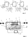
- FIG. 1 For example, heat sources at two different temperature levels can be combined with a heat pump recovering the heat of condensation from multiple units and re-using condensed water for renewed steam generation.
- Example 1 Steam assisted desorption process.
- the process is shown in Figure 10 and comprises, after a step of loading the adsorber with gaseous carbon dioxide under ambient atmospheric pressure and temperature, the following stages:
- One embodiment of a steam assisted desorption process was investigated for its application to direct air capture of CO 2 .
- the process comprised evacuation, temperature swing under vacuum up to the desorption temperature, steam purge under vacuum, cooling and re-pressurization.
- 40 g of amine functionalized adsorbent material was loaded with CO 2 by flowing ambient atmospheric air with a relative humidity of 60% and a temperature of 30°C through a vacuum chamber in which the sorbent is held.
- the chamber was evacuated to 200 mbar abs and subsequently heated with an external heat source at 110°C to about 100°C.
- this stage Tempoture Swing under Vacuum
- a quantity of CO 2 is released corresponding to 0.54 mmol/g.
- Example 2 The process of Example 2 was repeated with various steam flow rates, heat source temperatures, desorption pressures and various sorbent materials. The results are summarized in the following Table 1. All experiments were conducted with 40g of amine functionalized adsorbent. Table 1 Selected steam assisted desorption experiments Desorption Pressure (mbar abs ) Heat source temperature / Sorbent temperature (°C) Steam flow rate (g/h) Stage Temperature Swing under Vacuum Capacity (mmol/g) Stage Steam Purge under Vacuum Capacity (mmol/g Total Capacity (mmol/g) Dilution at max capacity (nH 2 O : n CO 2 ) 400 95/88 20 0.118 0.536 0.653 26:1 200 110 / 100 2.5 0.542 0.458 1.000 3.3 : 1 200 110/100 5 0.53 0.475 1.005 6.3 : 1 200 102 / 96 10 0.445 0.597 1.043 20 : 1 100 102 / 96 10 0.556 0.450 1.006 6 :
- a reduction of the desorption pressure at a constant desorption temperature favors the release of CO 2 in Temperature Swing under Vacuum as does an increase in the desorption temperature at a constant pressure.
- An increased release of CO 2 in stage Temperature Swing under Vacuum reduces the necessary steam demand of stage Steam Purge under Vacuum to achieve an attractive cyclic yield.
- Increasing the steam flow rate increases the cyclic yield by increasing the CO 2 released in stage Steam Purge under Vacuum. Practically there are certain limitations on these parameters which define the operation of the preferred embodiment. Pumping out the desorbed gas at a vacuum pressure of significantly less than 100 mbar abs can represent increased process cost for DAC applications where not only pump work but also the capital investment for larger volume throughput pumps must be considered.
- desorption pressures of significantly less than 100 mbar abs may become economically critical.
- desorption pressures higher than 200 mbar may result in low yields and high steam demands as demonstrated by the results of a 400 mbar desorption pressure experiment.
- Desorption temperatures as here shown should be as high as possible to achieve the largest release of CO 2 in stage temperature swing under vacuum. In the temperature range 95°C - 110°C, the price of heat changes little, making it attractive to work with the highest possible temperature which avoids damage to the amines groups of the adsorbent.
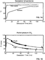
- Fig. 15 shows the partial CO 2 pressure for two desorption processes at 200 mbar abs and 110 °C heat source temperature using 2.5 g/h and 5 g/h steam flows.
- one possible attractive and practical operation parameter set for the investigated process was found to consist of 100-115 °C heat source temperature, 150-250 mbar abs desorption pressure and a steam to CO 2 molar ratio of less than 8:1 corresponding to less than approx. 0.1-0.2 kg steam/h/kg sorbent. This combination as shown above yields the desired approx. 1 mmol/g in cyclic operation.
- This parameter set is specific to the selected process parameters and investigated sorbent and is not obvious from the prior art.
- the behavior of this process of this invention is substantially superior to a conventional pure steam purge at atmospheric pressure as it is known in the prior art.
- the dilution necessary to reach the same cyclic capacity for a pure steam purge is in direct proportion to the partial pressure of CO 2 .
- a pure steam purge process at atmospheric pressure would require 40 moles of steam for each mole of CO 2 released.
- Such a steam demand might not be economically feasible from the viewpoint of energy for steam generation and capital costs for infrastructure such as steam generators, water handling equipment and piping.
- the process of the preferred embodiment achieves the same CO 2 partial pressure with significantly lower steam demand.
- the process of this invention represents a significant improvement over the conventional temperature vacuum swing process due to a doubling in the cyclic capacity. Further, because the low steam demand of the preferred process represents only a small increase in the additional energy which must be supplied for stage Steam Purge under Vacuum, an overall decrease in specific energy demand per ton of CO 2 is achieved, compared to a conventional temperature vacuum swing process. A comparison between processes with and without the recovery of the heat of vaporization of steam is given in Example 4.
- Example 4 Energy analysis of sorbent regeneration processes.
- Example 1 The possible process of Example 1 was analyzed for energy demand with one possible heat recovery embodiment consisting of a heat pump between steam generation and condensation heat exchangers. For comparison the energy demand is also reported without heat recovery.
- the energy analysis omits electricity demand of the vacuum system which is typically on the order of 100kWh per ton CO2.
- the operation parameters and resulting cyclic capacities determined in Example 2 are used for the analysis along with the physical properties of an amine functionalized adsorbent shown in the following parameter table.
- the sorbent mass was derived from one possible configuration for the unit.
- Sorbent Specific heat 1.4 kJ/kg/K Water cyclic capacity 3...8 mmol/g (40%...80% relative humidity) Heat of H 2 O desorption 47 kJ/mol H 2 O Heat of CO 2 desorption 70 kJ/mol CO 2 Process Steam dilution ratio in Stage Steam Purge under Vacuum 3.3 : 1 mol H 2 O : mol CO 2 Sorbent mass within unit 700 kg COP Heat Pump 8 Heat of vaporization of water 2260 kJ/kg Volume purge ratio for Stage Pre-Purge 10
- the total thermal energy, steam and electrical energy demand is shown in the following table for the case of one preferred embodiment with the heat recovery system.
- a pure steam process of the prior art has 5 times higher energy and 17 times higher steam demand than the process of the disclosed invention, inducing high costs.
- the flow rate for the prior art process requires piping with a 170 mm bore (i.e. DN 200) with the correspondingly sized valves and connections.
- the process of the disclosed invention can use much more economical 45 mm (i.e. DN 50) piping with more readily available and significantly less expensive process equipment.
- Example 5 Improvement of sorbent lifetime.
- stage Pre-Purge strongly reduces exposure of the sorbent to high temperature oxygen which is known to significantly reduce cyclic capacity.
- Stage Pre-Purge was evaluated experimentally with an amine functionalized adsorbent in a conventional temperature-vacuum swing process. It was found that by pre-purging the sorbent chamber with an inert gas and removing oxygen before beginning the temperature swing, the reduction in cyclic capacity can be reduced by 50%.
- Fresh sorbent was tested before and after 200 temperature-vacuum swing (TVS) cycles achieving sorbent temperatures of more than 90°C with and without Pre-Purge.
- TVS temperature-vacuum swing
- Fig. 16 show the oxygen concentration in the desorption gas during a typical temperature vacuum swing desorption of CO 2 captured from ambient atmospheric air.
- the concentration of oxygen in the desorption gas sinks rapidly from a near atmospheric concentration as CO 2 gas is released and effectively purges the vacuum chamber of the majority of oxygen achieving a sub 1% concentration roughly 26 minutes after the start of desorption.
- Fig. 17 shows a zoomed portion of the Fig. 16 focusing on oxygen concentrations below 100 ppm.
- the oxygen concentration sinks below 1 ppm roughly at 28.7 min after the start of desorption.
Landscapes
- Chemical & Material Sciences (AREA)
- Engineering & Computer Science (AREA)
- Analytical Chemistry (AREA)
- General Chemical & Material Sciences (AREA)
- Oil, Petroleum & Natural Gas (AREA)
- Chemical Kinetics & Catalysis (AREA)
- Health & Medical Sciences (AREA)
- Biomedical Technology (AREA)
- Environmental & Geological Engineering (AREA)
- Separation Of Gases By Adsorption (AREA)
- Solid-Sorbent Or Filter-Aiding Compositions (AREA)
- Treating Waste Gases (AREA)
- Carbon And Carbon Compounds (AREA)
Claims (14)
- Verfahren zur Abtrennung von gasförmigem Kohlendioxid aus einem Gasgemisch, vorzugsweise Luft oder Rauchgas, das das gasförmige Kohlendioxid sowie weitere von gasförmigem Kohlendioxid verschiedene Gase enthält, durch zyklische Adsorption/Desorption unter Verwendung eines Sorptionsmaterials, das das gasförmige Kohlendioxid adsorbiert, unter Verwendung
einer Einheit (1), die eine Adsorberstruktur (6) mit dem Sorptionsmaterial enthält, wobei die Einheit auf einen Vakuumdruck von 400 mbarabs oder weniger evakuiert werden kann und die Adsorberstruktur (6) auf eine Temperatur von mindestens 80°C für die Desorption mindestens des gasförmigen Kohlendioxids erhitzt werden kann und die Einheit für den Durchfluss des Gasgemischs und für dessen Kontakt mit dem Sorptionsmaterial für den Adsorptionsschritt geöffnet werden kann, wobei das Verfahren die folgenden aufeinanderfolgenden und in dieser Reihenfolge wiederholten Schritte umfasst:(a) Inkontaktbringen des Gasgemischs mit dem Sorptionsmaterial, um zumindest das gasförmige Kohlendioxid an dem Sorptionsmaterial unter atmosphärischen Umgebungsdruckbedingungen im Bereich von 0,8 bis 1,1 barabs und atmosphärischen Umgebungstemperaturbedingungen im Bereich von -40 bis 60°C in einem Adsorptionsschritt adsorbieren zu lassen;(b) Evakuieren der Einheit (1) auf einen Druck im Bereich von 20-400 mbarabs und Erhitzen des Sorptionsmaterials in der Einheit (1) auf eine Temperatur im Bereich von 80-130°C in einem Desorptionsschritt und Extrahieren zumindest des desorbierten gasförmigen Kohlendioxids aus der Einheit (1) und Abtrennen des gasförmigen Kohlendioxids von Wasser durch Kondensation in oder stromabwärts der Einheit (1)
wobei Schritt (b) die folgenden aufeinanderfolgenden Schritte umfasst:(b1) Evakuieren der Einheit (1) auf einen Anfangsdruck im Bereich von 20-400 mbarabs;(b2) Vorheizen des Sorptionsmaterials auf eine Temperatur im Bereich von 35-80°C für eine Dauer von weniger als 30 min Desorbieren eines Teils von CO2 und H2O aus dem Sorptionsmaterial;(b3) optionales Injizieren eines anfänglichen Teils von Dampf in einem Vorspülschritt bei einer Temperatur im Bereich von 35-80°C;(b4) weiteres Erhitzen des Sorptionsmaterials auf eine Temperatur im Bereich von 80-130°C und Extrahieren eines Teils des gasförmigen Kohlendioxids aus der Einheit (1) und Abtrennen des gasförmigen Kohlendioxids von Wasser durch Kondensation in oder stromabwärts der Einheit (1);(b5) Injizieren von Dampf in die Einheit, um das Sorptionsmaterial unter Sättigungsdampf- oder Heißdampfbedingungen mit einer Heißdampftemperatur von bis zu 130 °C bei einem Druckniveau im Bereich von 50-400 mbarabs zu durchströmen und zu kontaktieren, während das Sorptionsmaterial weiterhin auf eine Temperatur im Bereich von 80-130 °C erhitzt wird, und Extrahieren eines weiteren Teils des gasförmigen Kohlendioxids aus der Einheit (1) und Abtrennen des gasförmigen Kohlendioxids von Wasser durch Kondensation in oder stromabwärts der Einheit (1);(c) aktives Kühlen des Sorptionsmaterials unter einem Druck wie in Schritt (b) auf eine Temperatur, die größer oder gleich der atmosphärischen Umgebungstemperatur ist, und erneutes Unterdrucksetzen der Einheit auf atmosphärische Umgebungsdruckbedingungen;und wobei das molare Verhältnis von Dampf, der während des gesamten Schritts (b) eingespritzt wird, zu dem gasförmigen Kohlendioxid, das während des gesamten Schritts (b) freigesetzt wird, weniger als 40:1 beträgt. - Verfahren nach Anspruch 1, wobeiSchritt (b1) das Evakuieren der Einheit (1) auf einen Anfangsdruck im Bereich von 20-200 mbarabs oder 50-150 mbarabs beinhaltet, vorzugsweise ohne aktives Erhitzen oder Kühlen des Sorptionsmaterials;und/oder wobei Schritt (b2) das Vorheizen des Sorptionsmaterials auf eine Temperatur im Bereich von 45-75°C beinhaltet;und/oder wobei Schritt (b4) das weitere Erhitzen des Sorptionsmaterials auf eine Temperatur im Bereich von 90-120°C und das Extrahieren eines Teils des gasförmigen Kohlendioxids aus der Einheit (1) und das Trennen des gasförmigen Kohlendioxids von Wasser durch Kondensation in oder stromabwärts der Einheit (1) umfasst;und/oder wobei Schritt (b5) das Einspritzen von Dampf in die Einheit beinhaltet, um das Sorptionsmaterial unter Sattdampf- oder Heißdampfbedingungen mit einer Heißdampftemperatur von bis zu 130 °C bei einem Druckniveau im Bereich von 100-300 mbarabs zu durchströmen und zu kontaktieren, während das Sorptionsmaterial weiterhin auf eine Temperatur im Bereich von 80-130 °C erhitzt wird, vorzugsweise im Bereich von 90-120°C, erhitzt wird und ein weiterer Teil des gasförmigen Kohlendioxids aus der Einheit (1) entnommen wird und gasförmiges Kohlendioxid durch Kondensation in oder stromabwärts der Einheit (1) von Wasser getrennt wird;und/oder wobei in den Schritten (b2) bis (b5) der Druck in der Einheit vorzugsweise gegenüber Schritt (b1) ansteigen kann und/oder im Bereich von 50-400 mbarabs, vorzugsweise im Bereich von 100-300 mbarabs, gehalten wird;und/oder wobei die Wärmeübertragung in den Schritten (b2) und (b4) durch ein in der Adsorberstruktur (6) vorgesehenes Wärmetauscherelement (2) bewirkt wird, vorzugsweise unter Verwendung eines durch das Wärmetauscherelement zirkulierenden Wärmeaustauschfluids.
- Verfahren nach Anspruch 1, wobei in Schritt (b2) das Sorptionsmaterial unter Verwendung eines in das Sorptionsmaterial integrierten Wärmetauschers auf eine Temperatur im Bereich von 45-75°C erwärmt wird, und/oder in Schritt (b4) das Sorptionsmaterial unter Verwendung eines in das Sorptionsmaterial integrierten Wärmetauschers auf eine Temperatur im Bereich von 90-120°C erwärmt wird, und/oder wobei Schritt (c) eine aktive Kühlung der Adsorberstruktur auf eine Temperatur von weniger als 60°C, vorzugsweise auf eine Temperatur von weniger als 50°C, einschließt, die vorzugsweise durch ein in der Adsorberstruktur (6) vorgesehenes Wärmetauscherelement (2) bewirkt wird, vorzugsweise unter Verwendung eines durch das Wärmetauscherelement zirkulierenden Wärmeaustauschfluids.
- Verfahren nach einem der vorhergehenden Ansprüche 1 bis 3, wobei in Schritt (b3) eine anfängliche Dampfmenge in einem Vorreinigungsschritt injiziert wird, wobei vorzugsweise in diesem Vorreinigungsschritt (b3) der injizierte Dampf durch eine Sättigungstemperatur im Bereich von 17-60°C, vorzugsweise im Bereich von 33-58°C, gekennzeichnet ist, was einem Sättigungsdruckbereich von 20-200 mbarabs, vorzugsweise 50-150 mbarabs, entspricht, wobei ferner vorzugsweise das gesamte injizierte Dampfvolumen im Vorspülschritt (b3) bei dem in der Anlage herrschenden Druck weniger als dem 20-fachen, vorzugsweise weniger als dem 10-fachen des Volumens der Desorptionskammer der Anlage (1) entspricht und/oder wobei ferner vorzugsweise das molare Verhältnis von Dampf, der während des Vorspülschritts (b3) eingespritzt wird, zu dem während des gesamten Schritts (b) freigesetzten gasförmigen Kohlendioxid weniger als 1: 1, vorzugsweise weniger als 0. 5:1.
- Verfahren nach einem der vorhergehenden Ansprüche 1 - 4, wobei eine Niedertemperatur-Wärmequelle (12), die Wärme im Bereich von 40-80°C, vorzugsweise im Bereich von 45-75°C, liefert, die Wärme zur Dampferzeugung in einer Dampf-Wärmetausch- oder -Erzeugungseinheit (5) zur Verwendung während Schritt (b5) und/oder während Schritt (b3) bereitstellt,und wobei vorzugsweise die Niedertemperatur-Wärmequelle (12) auch die Wärme zum Vorwärmen des Sorptionsmaterials während Schritt (b2) liefert,und wobei eine Hochtemperatur-Wärmequelle (11), die Wärme im Bereich von 80-130°C, vorzugsweise im Bereich von 90-120°C bereitstellt, die zum Erwärmen des Sorptionsmaterials während Schritt (b5) verwendete Wärme liefert.
- Verfahren nach einem der vorhergehenden Ansprüche 1 bis 5, wobei das molare Verhältnis von Dampf, der während des gesamten Schritts (b) injiziert wird, zu dem gasförmigen Kohlendioxid, das während des gesamten Schritts (b) freigesetzt wird, weniger als 10 beträgt: 1 ist, und wobei vorzugsweise der Druck in den Schritten (b3)-(b5) im Bereich von 100-300 mbarabs liegt und wobei weiter vorzugsweise die Temperatur in den Schritten (b2) und (b3) auf einen Wert im Bereich von 45-75°C erhöht wird und wobei weiter vorzugsweise die Temperatur in den Schritten (b4) und (b5) auf einen Wert im Bereich von 90-120°C erhöht wird,
und/oder wobei der in Schritt (b5) verwendete Dampf einen Sättigungsdruck im Bereich von 50-400 mbarabs, vorzugsweise im Bereich von 100-300 mbarabs, und eine entsprechende Sättigungstemperatur im Bereich von 33-76°C, vorzugsweise 45-69°C, aufweist. - Verfahren nach einem der vorhergehenden Ansprüche, wobei eine Mehrzahl von seriellen Einzelaggregaten (1) mit Dampf versorgt wird, der von einer Mehrzahl von Dampferzeugungs- oder Dampfwärmetauschereinheiten (5, 13) erzeugt wird, wobei abgesehen von einer stromaufwärts gelegenen Dampferzeugungseinheit (5) diese Dampfversorgungen (13) zwischen benachbarten Einzelaggregaten (1) vorgesehen sind,und wobei Dampf (4-1) einer ersten Einheit (1-1) durch den stromaufwärtigsten Wärmetauscher (5) mit einem ersten Druck (P1) zugeführt wird, und der Dampf (7-1) stromabwärts der ersten Einheit (1-1) zusammen mit der Entnahme von gasförmigem Kohlendioxid aus der ersten Einheit (1-1) zusammen mit der Entnahme von gasförmigem Kohlendioxid aus der ersten Einheit (1-1) in einer Wärmeaustausch- und/oder Dampferzeugungseinheit (13) stromabwärts der ersten Einheit (1-1) zumindest teilweise kondensiert wird, wodurch zumindest ein Teil der Wärme für die Erzeugung von Dampf (4-2) an eine nachfolgende Einheit (1-2) bei einem niedrigeren Druck (P2) als dem ersten Druck (P1) ((P2) < (P1)) geliefert wird,wobei der Dampf (7-2) stromabwärts der nachfolgenden Einheit (1-2) zusammen mit der Extraktion von gasförmigem Kohlendioxid, das aus der nachfolgenden Einheit (1-2) stammt, zumindest teilweise stromabwärts der nachfolgenden Einheit (1-2) in einer Wärmeaustausch- und/oder Dampferzeugungseinheit (13) kondensiert wird, wodurch zumindest ein Teil der Wärme für die Erzeugung von Dampf (4-3) zu einer weiteren Einheit (1-3) bei einem niedrigeren Druck (P3) ((P3) < (P2)) als dem in der vorherigen Einheit (1-2) bereitgestellt wird,gefolgt von einer zumindest teilweisen Kondensation des Dampfes (7-3) stromabwärts der weiteren Einheit (1-3), zusammen mit einer Extraktion von gasförmigem Kohlendioxid, das aus der weiteren Einheit (1-3) stammt,und/oder vorzugsweise gefolgt von einer seriellen Abfolge weiterer Einheiten, die jeweils unter einem nacheinander niedrigeren Druck stehen, wobei der Dampf stromabwärts jeder Einheit (1) zusammen mit der Entnahme von gasförmigem Kohlendioxid, das aus der jeweiligen Einheit stammt, stromabwärts der jeweiligen Einheit in einer Wärmetausch- und/oder Dampferzeugungseinheit (13) zumindest teilweise kondensiert wird, wodurch zumindest ein Teil der Wärme für die Dampferzeugung für eine nächste Einheit bei niedrigerem Druck als in der vorherigen Einheit bereitgestellt wird.
- Verfahren nach einem der vorangehenden Ansprüche 1-4, 6 oder 7, wobei eine einzige Wärmequelle (11) verwendet wird, um die Wärme für die Dampferzeugung und die Wärme für die Erwärmung des Sorptionsmaterials in Schritt (b) bereitzustellen, wobei ein Wärmetauschfluid verwendet wird, das durch ein Wärmetauscherelement (2), das in der Adsorberstruktur (6) vorgesehen ist, und eine Dampfwärmetauschereinheit (5) in einer parallelen Strömungsanordnung oder in einer seriellen Strömungsanordnung strömt, wobei es im Falle einer seriellen Strömungsanordnung zuerst durch das Wärmetauscherelement (2), das in der Adsorberstruktur (6) vorgesehen ist, und anschließend durch die Dampfwärmetauschereinheit (5) strömt.
- Verfahren nach einem der vorhergehenden Ansprüche, wobei aus injiziertem Dampf und desorbiertem Wasser aus dem Gasgemisch stammender Dampf im Gemisch mit gasförmigem Kohlendioxid, das in Schritt (b), vorzugsweise in den Schritten (b2), (b3), (b4) und (b5), aus der Anlage (1) entnommen wurde, in einem Kondensationswärmetauscher (8) kondensiert wird, der das Kohlendioxid (16) zumindest teilweise von dem kondensierten Wasser (17) trennt, und
wobei vorzugsweise die in dem Kondensationswärmetauscher (8) erzeugte Kondensationswärme, gegebenenfalls nach weiterer Erhöhung der Temperatur mittels einer Wärmepumpe (10), zur Erzeugung von Dampf zur Verwendung in Schritt (b) für dieselbe Einheit (1) oder für andere Einheiten und/oder zur Beheizung anderer Einheiten durch in deren Adsorberstrukturen (6) vorgesehene Wärmetauscherelemente (2), vorzugsweise während Schritt (b2), verwendet wird. - Verfahren nach einem der vorhergehenden Ansprüche, bei dem Dampf und gasförmiges Kohlendioxid, die in Schritt (b) aus der Einheit entnommen werden, zunächst in einem Rückverdichter (14) verdichtet werden und dann einen Kesselrückverdampfer (15) passieren, der den Dampf kondensiert und ihn von dem Kohlendioxid trennt und die freigesetzte Wärme zur Erzeugung von Dampf zur Verwendung in Schritt (b) verwendet.
- Verfahren nach einem der vorhergehenden Ansprüche, wobei das Sorptionsmittel ein schwach basisches Ionenaustauscherharz, vorzugsweise mit adsorbierenden Amingruppen, oder eine aminfunktionalisierte Cellulose ist.
- Verfahren nach einem der vorhergehenden Ansprüche, wobei im Innenraum der Anlage (1) innerhalb der Wandbegrenzungen der zu evakuierenden Anlage und stromaufwärts des Sorptionsmaterials eine Wärmetausch- oder Dampferzeugungseinheit (5) angeordnet ist, die den Dampf für Schritt (b) erzeugt, und/oder wobei im Innenraum der Anlage (1) innerhalb der Wandbegrenzungen der zu evakuierenden Anlage und stromabwärts des Sorptionsmaterials der Dampfkondensationswärmetauscher (8) zur Kondensation von Dampf und/oder Abtrennung von gasförmigem Kohlendioxid angeordnet ist.
- Verfahren nach einem der vorhergehenden Ansprüche, wobei stromabwärts der Einheit kondensierter oder nicht kondensierter Dampf, gegebenenfalls nach weiterer Wärmezufuhr, als Dampf für Schritt (b) der gleichen oder einer anderen Einheit oder zur Erzeugung von Dampf für Schritt (b) der gleichen oder einer anderen Einheit verwendet wird.
- Verwendung eines Verfahrens nach einem der vorhergehenden Ansprüche zur Abtrennung von Kohlendioxid aus einem Umgebungsluftstrom.
Applications Claiming Priority (2)
| Application Number | Priority Date | Filing Date | Title |
|---|---|---|---|
| EP14176454 | 2014-07-10 | ||
| PCT/EP2015/064791 WO2016005226A1 (en) | 2014-07-10 | 2015-06-30 | Steam assisted vacuum desorption process for carbon dioxide capture |
Publications (2)
| Publication Number | Publication Date |
|---|---|
| EP3166708A1 EP3166708A1 (de) | 2017-05-17 |
| EP3166708B1 true EP3166708B1 (de) | 2021-11-10 |
Family
ID=51176183
Family Applications (1)
| Application Number | Title | Priority Date | Filing Date |
|---|---|---|---|
| EP15731616.7A Active EP3166708B1 (de) | 2014-07-10 | 2015-06-30 | Dampfunterstütztes vakuumdesorptionsverfahren zur kohlendioxidabscheidung |
Country Status (4)
| Country | Link |
|---|---|
| US (1) | US10279306B2 (de) |
| EP (1) | EP3166708B1 (de) |
| JP (1) | JP6622302B2 (de) |
| WO (1) | WO2016005226A1 (de) |
Cited By (7)
| Publication number | Priority date | Publication date | Assignee | Title |
|---|---|---|---|---|
| DE202022002306U1 (de) | 2022-10-26 | 2023-02-06 | Fritz Curtius | Energieerzeuger mit Erdgas |
| DE202022002612U1 (de) | 2022-08-26 | 2023-03-13 | Fritz Curtius | Energieerzeuger mit Erdgas |
| DE102022004003A1 (de) | 2022-08-04 | 2024-02-15 | Fritz Curtius | Energieerzeuger mit Erdgas |
| DE102022004591A1 (de) | 2022-08-26 | 2024-02-29 | Fritz Curtius | Energieerzeuger mit Erdgas. |
| WO2025036929A1 (de) | 2023-08-17 | 2025-02-20 | Volkswagen Ag | Vorrichtung und verfahren zur abtrennung eines gases und/oder von luftfeuchte aus der umgebungsluft |
| DE102023122086A1 (de) | 2023-08-17 | 2025-02-20 | Volkswagen Aktiengesellschaft | Sorptionszelle und Anlage zur Abtrennung von einem Gas und/oder Luftfeuchte aus Umgebungsluft sowie Verfahren zur Herstellung einer Sorptionszelle |
| EP4674507A1 (de) * | 2024-07-05 | 2026-01-07 | Siemens Aktiengesellschaft | Verfahren zum absondern von kohlendioxid aus einem gasgemisch und vorrichtung hierzu |
Families Citing this family (116)
| Publication number | Priority date | Publication date | Assignee | Title |
|---|---|---|---|---|
| MX2011001898A (es) | 2008-08-21 | 2011-05-02 | Carbon Engineering Ltd Partnership | Metodo de captura de dioxido de carbono e instalacion. |
| US11007470B2 (en) | 2013-04-18 | 2021-05-18 | Climeworks Ag | Low-pressure drop structure of particle adsorbent bed for improved adsorption gas separation process |
| JP6713301B2 (ja) * | 2016-03-01 | 2020-06-24 | 株式会社西部技研 | 吸収式除去・濃縮装置 |
| JP6957497B2 (ja) | 2016-03-31 | 2021-11-02 | スヴァンテ インコーポレイテッド | 再生のために蒸気を使用する吸着ガス分離 |
| CA3295632A1 (en) | 2016-06-14 | 2026-03-02 | Olcv Ce Holdings, Ulc | Capturing carbon dioxide |
| NO20161306A1 (en) * | 2016-08-16 | 2018-02-19 | Greencap Solutions As | System and method for climate control i closed spaces |
| WO2018057780A1 (en) | 2016-09-21 | 2018-03-29 | Donald Williams | Carbon capture system, apparatus, and method |
| EP3535044A1 (de) | 2016-11-04 | 2019-09-11 | Climeworks AG | Struktur mit niedrigem druckabfall eines partikeladsorptionsbetts für verbessertes adsorptionsgastrennungsverfahren |
| EP3548565A1 (de) | 2016-11-29 | 2019-10-09 | Climeworks AG | Verfahren zur entfernung von co2 aus atmosphärischer luft oder aus anderen co2-haltigen gasen zur erzielung von co2-emissionsreduktionen oder negativen co2-emissionen |
| US10583389B2 (en) | 2016-12-21 | 2020-03-10 | Genesis Systems Llc | Atmospheric water generation systems and methods |
| BR112019013078B1 (pt) | 2016-12-23 | 2024-01-02 | Carbon Engineering Ltd | Método e sistema para sintetizar combustível a partir de fonte de dióxido de carbono diluído |
| WO2018200526A1 (en) * | 2017-04-24 | 2018-11-01 | Oxy Usa, Inc. | Process for carbon dioxide recapture with improved energy recapture |
| DE102017125415B8 (de) * | 2017-10-30 | 2018-10-25 | clean energy one gmbh | Windenergieanlage mit CO2 Sammler und Windenergieanlagen-CO2-Sammler-Steuerungs- bzw. Betriebsverfahren |
| WO2019191651A1 (en) * | 2018-03-29 | 2019-10-03 | Eisenberger, Peter And Chichilnisky, Graciela, Jointly | Food grade co2 capture system |
| CA3096891A1 (en) | 2018-04-17 | 2019-10-24 | Carbon Engineering Ltd. | Hydration of gas streams |
| ES2952749T3 (es) * | 2018-06-14 | 2023-11-03 | Climeworks Ag | Método y dispositivo para la adsorción/desorción de dióxido de carbono de corrientes de gas con unidad de recuperación de calor |
| DE102018212898A1 (de) * | 2018-08-02 | 2020-02-27 | Thyssenkrupp Ag | Regenerativer CO2-Absorber für ein Unterseeboot |
| US11446601B2 (en) | 2019-01-02 | 2022-09-20 | ExxonMobil Technology and Engineering Company | CO2 capture from dilute sources |
| AU2020210754A1 (en) | 2019-01-23 | 2021-07-08 | Blue Planet Systems Corporation | Carbonate aggregate compositions and methods of making and using the same |
| DK3725391T3 (da) | 2019-04-18 | 2021-06-21 | Climeworks Ag | Indretning til co2-optagelse fra luft ved direkte luftindfangning med højt gennemløb og fremgangsmåde til funktion deraf |
| WO2020254208A1 (en) | 2019-06-21 | 2020-12-24 | Climeworks Ag | Adsorber structure for gas separation processes |
| EP3791950A1 (de) * | 2019-09-11 | 2021-03-17 | Vito NV | System zur direkten kohlendioxidabscheidung |
| US11571657B2 (en) | 2019-10-24 | 2023-02-07 | Aeolus Works LLC | System and method for extracting carbon dioxide from atmospheric air via pressure-swing absorption |
| US11452968B2 (en) | 2019-10-24 | 2022-09-27 | Aeolus Works LLC | System and method for extracting carbon dioxide from atmospheric air via pressure-swing absorption |
| MX2023004727A (es) * | 2019-10-24 | 2023-07-04 | Aeolus Works LLC | Sistema y metodo para la extraccion de dioxido de carbono del aire atmosferico mediante absorcion por oscilacion de presion. |
| WO2021089915A1 (en) * | 2019-11-04 | 2021-05-14 | Soletair Power Oy | Method and apparatus for recovering carbon dioxide and use of the method |
| WO2021159202A1 (en) * | 2020-02-16 | 2021-08-19 | Niall Davidson | Carbon negative data centers and services |
| EP4121191A4 (de) * | 2020-03-17 | 2024-07-17 | Arizona Board of Regents on behalf of Arizona State University | Autothermes direktes lufterfassungssystem |
| US20230173427A1 (en) * | 2020-05-27 | 2023-06-08 | Climeworks Ag | Atmospheric steam desorption for direct air capture |
| US20230201759A1 (en) | 2020-05-27 | 2023-06-29 | Climeworks Ag | Methods and devices for steam driven carbon dioxide capture |
| US12582935B2 (en) | 2020-05-29 | 2026-03-24 | Climeworks Ag | Method for capture of carbon dioxide from ambient air and corresponding adsorber structures with a plurality of parallel surfaces |
| CN116348412A (zh) | 2020-06-09 | 2023-06-27 | 全球温控营运有限责任公司 | 连续运动直接空气捕集系统 |
| WO2021259760A1 (en) | 2020-06-22 | 2021-12-30 | Climeworks Ag | Method and apparatus for direct air capture of carbon dioxide by using a solid polymeric support material functionalized with amino functionalities and the use of this material for carbon dioxide capture from air |
| GB202014830D0 (en) * | 2020-09-21 | 2020-11-04 | Rolls Royce Plc | Carbon dioxide capture |
| GB2592707B (en) * | 2020-11-26 | 2022-03-30 | Provost Fellows Found Scholars & Other Members Board College Holy & Und | Providing heat energy to direct air carbon dioxide capture processes using waste heat from data centre |
| EP4251304A4 (de) * | 2020-11-29 | 2024-11-27 | Terrafixing Inc. | Direkte lufterfassung und konzentration von co2 unter verwendung von adsorptionsmitteln |
| JP2023553031A (ja) * | 2020-12-09 | 2023-12-20 | アリゾナ・ボード・オブ・リージェンツ・オン・ビハーフ・オブ・アリゾナ・ステイト・ユニバーシティー | 資源効率の良い二酸化炭素捕捉のためのシステムおよび方法 |
| DE102020215687A1 (de) * | 2020-12-11 | 2022-06-15 | Thyssenkrupp Ag | CO2-Absorber |
| US12276090B2 (en) | 2020-12-17 | 2025-04-15 | Genesis Systems Llc | Atmospheric water generation systems and methods |
| US11684888B2 (en) * | 2021-01-08 | 2023-06-27 | Saudi Arabian Oil Company | Integrated heat management systems and processes for adsorbed natural gas storage facilities |
| US11739506B2 (en) | 2021-02-05 | 2023-08-29 | General Electric Company | Water recovery system including integrated contactor with thermally-enhanced recovery |
| US12059648B2 (en) | 2021-02-05 | 2024-08-13 | Ge Infrastructure Technology Llc | Carbon dioxide capture system and method of capturing carbon dioxide |
| EP4301491A4 (de) | 2021-03-04 | 2024-11-20 | Echeneidae Inc. | System und verfahren zur mobilen kohlenstoffabscheidung |
| IL305236A (en) | 2021-03-09 | 2023-10-01 | Genesis Systems Llc | Systems and methods for producing atmospheric water using membrane-based water extraction |
| AU2022308829B2 (en) | 2021-07-07 | 2025-04-17 | Genesis Systems Llc | Atmospheric water generation systems and methods by absorption using ultrasound or microwave for regeneration of the solvent |
| WO2023283335A1 (en) | 2021-07-07 | 2023-01-12 | Genesis Systems Llc | Surface covering for canopy and electrical energy generation and storage system |
| KR20240040087A (ko) | 2021-07-21 | 2024-03-27 | 클라임웍스 아게 | 직접 공기 포집을 위한 아민 관능화된 섬유 |
| WO2023002235A1 (en) * | 2021-07-22 | 2023-01-26 | Hamon & Cie (International) | Air cooling system associated to a co2 direct gas capture system |
| US11654393B2 (en) * | 2021-08-29 | 2023-05-23 | Carbon Capture Inc. | Temperature vacuum swing adsorption process suited for carbon capture to regenerate sorbents using the CO2 product gas as the heat transfer medium |
| KR102405949B1 (ko) * | 2021-09-06 | 2022-06-07 | 주식회사 바우만 | Tsa와 vsa기술을 병합한 고순도 이산화탄소 생산설비 |
| JP7690847B2 (ja) * | 2021-10-28 | 2025-06-11 | トヨタ自動車株式会社 | 二酸化炭素吸着器の導入空気量制御装置 |
| KR20240151736A (ko) | 2021-12-16 | 2024-10-18 | 클라임웍스 아게 | 습도 안정성 폴리스티렌디비닐벤젠 아민 관능화된 중합체 흡착제를 이용한 co2 흡착 시스템 및 co2 흡착 방법 |
| CN118647588A (zh) | 2021-12-20 | 2024-09-13 | 蓝色星球系统公司 | 生产建筑材料的方法 |
| JP7132475B1 (ja) | 2021-12-27 | 2022-09-07 | 岡野 浩志 | 空調給気可能な二酸化炭素ガス分離濃縮装置 |
| US11617981B1 (en) | 2022-01-03 | 2023-04-04 | Saudi Arabian Oil Company | Method for capturing CO2 with assisted vapor compression |
| US20250187913A1 (en) | 2022-02-25 | 2025-06-12 | Fld Technologies Gmbh | Method for removing and immobilising carbon dioxide from the atmosphere and/or a waste gas |
| US12326278B2 (en) | 2022-02-28 | 2025-06-10 | EnhancedGEO Holdings, LLC | Geothermal power from superhot geothermal fluid and magma reservoirs |
| US11918952B2 (en) * | 2022-05-18 | 2024-03-05 | ExxonMobil Technology and Engineering Company | Cyclical CO2 capture with integrated heat pump |
| JP7174205B1 (ja) | 2022-05-23 | 2022-11-17 | 岡野 浩志 | 空調給気も可能な空気中二酸化炭素をガス源とするドライアイス製造システム |
| JP2025518138A (ja) | 2022-05-27 | 2025-06-12 | ゼロ カーボン システムズ インコーポレイテッド | ハイスループット可動パネル直接空気回収システム |
| CN114849420B (zh) * | 2022-06-07 | 2023-06-27 | 西安热工研究院有限公司 | 一种基于气汽换热吸附装置的强化系统及方法 |
| US11944931B2 (en) | 2022-06-24 | 2024-04-02 | Climeworks Ag | Direct air capture device |
| EP4427833A1 (de) | 2023-03-08 | 2024-09-11 | Climeworks AG | Vorrichtung zur direkten lufterfassung |
| EP4543566A1 (de) | 2022-06-24 | 2025-04-30 | Climeworks AG | Vorrichtung zur direkten lufterfassung |
| JP2025521914A (ja) | 2022-07-01 | 2025-07-10 | ダブリュ.エル.ゴア アンド アソシエイツ,インコーポレイティド | 吸着ガス分離プロセス用の粒子吸着床のための外部支持体を備えた構造 |
| DE102022117409A1 (de) | 2022-07-13 | 2024-01-18 | Man Energy Solutions Se | Verfahren zur Abtrennung von Kohlenstoffdioxid aus der Umgebungsluft sowie Anlage zur Durchführung eines solchen Verfahrens |
| WO2024039641A1 (en) | 2022-08-15 | 2024-02-22 | W. L. Gore & Associates, Inc. | Structures and methods for enhancing capture of carbon dioxide from ambient air |
| US20240058743A1 (en) | 2022-08-16 | 2024-02-22 | ExxonMobil Technology and Engineering Company | Direct capture of co2 from air and point sources |
| JP2024034883A (ja) | 2022-09-01 | 2024-03-13 | 三菱重工業株式会社 | 二酸化炭素回収装置、及び二酸化炭素回収方法 |
| CN117678457A (zh) * | 2022-09-02 | 2024-03-12 | 青岛绿色发展研究院有限公司 | 一种利用二氧化碳的装置系统及方法 |
| CN115430254B (zh) * | 2022-09-07 | 2024-04-30 | 西安热工研究院有限公司 | 太阳能供热的旋转式空气捕碳器、碳捕集系统及方法 |
| US12134069B2 (en) | 2022-10-07 | 2024-11-05 | Carbon Capture Inc. | Mechanical vapor re-compressor heat pump for separating CO2 from water vapor in temperature-vacuum swing adsorption cycles |
| EP4360738A1 (de) * | 2022-10-26 | 2024-05-01 | Airbus Defence and Space GmbH | System zur abscheidung von co2 aus luft unter verwendung eines adsorptionsmaterials in einem elektromagnetischen induktionsverfahren |
| DE102022130004A1 (de) | 2022-11-14 | 2024-05-16 | Volkswagen Aktiengesellschaft | Prozessraum und Anlage zur Abtrennung von Kohlenstoffdioxid aus der Umgebungsluft |
| EP4622727A1 (de) * | 2022-11-22 | 2025-10-01 | Shell Internationale Research Maatschappij B.V. | Verfahren zum betrieb eines direkten lufterfassungsprozesses mit einem fraktalen netzwerklayout |
| WO2024112429A1 (en) * | 2022-11-22 | 2024-05-30 | The Regents Of The University Of California | Passive carbon capture device using solar energy |
| CN120265367A (zh) | 2022-11-30 | 2025-07-04 | Cims日本株式会社 | 二氧化碳回收方法及其使用的烧成设备 |
| CN120152777A (zh) * | 2022-12-06 | 2025-06-13 | 本田技研工业株式会社 | 二氧化碳回收装置 |
| WO2024129714A2 (en) | 2022-12-13 | 2024-06-20 | W. L. Gore & Associates, Inc. | Low-pressure drop structure of particle adsorbent bed for improved adsorption gas separation process |
| US12504203B2 (en) | 2023-02-10 | 2025-12-23 | EnhancedGEO Holdings, LLC | Reverse-flow magma-based geothermal generation |
| US11912573B1 (en) | 2023-03-03 | 2024-02-27 | EnhancedGEO Holdings, LLC | Molten-salt mediated thermochemical reactions using geothermal energy |
| WO2024184330A1 (en) | 2023-03-08 | 2024-09-12 | Climeworks Ag | Direct air capture device |
| WO2024184329A1 (en) | 2023-03-08 | 2024-09-12 | Climeworks Ag | Direct air capture device |
| CN121240914A (zh) * | 2023-03-31 | 2025-12-30 | 康明泰克股份有限公司 | 用于捕集二氧化碳的吸附器模块和反应器 |
| WO2024238622A2 (en) * | 2023-05-15 | 2024-11-21 | Ohio State Innovation Foundation | Membrane-adsorption process for direct air capture |
| DE102023204779A1 (de) | 2023-05-23 | 2024-11-28 | Siemens Energy Global GmbH & Co. KG | Verfahren zur Abtrennung von CO2 aus der Atmosphäre und Separationsvorrichtung, insbesondere zur Durchführung des Verfahrens |
| DE102023205150A1 (de) | 2023-06-01 | 2024-12-05 | Volkswagen Aktiengesellschaft | Sorptionsmittel mit speziellen Eigenschaften |
| DE102023119251A1 (de) | 2023-07-20 | 2025-01-23 | Volkswagen Aktiengesellschaft | Direct Air Capture Verfahren |
| DE102023119252A1 (de) | 2023-07-20 | 2025-01-23 | Volkswagen Aktiengesellschaft | Kombination einer stationären lufttrocknungsanlage mit direct air capture |
| WO2025024183A1 (en) * | 2023-07-24 | 2025-01-30 | Siemens Energy Global GmbH & Co. KG | Process of sub-atmospheric and low temperature. steam desorption for use with direct air carbon capture (dac) |
| DE102023119768A1 (de) | 2023-07-26 | 2025-01-30 | Man Energy Solutions Se | Lufttrocknungsvorrichtung einer DAC-Anlage, DAC-Anlage und Verfahren zum Betreiben derselben |
| CN116889779A (zh) * | 2023-07-26 | 2023-10-17 | 黑鲸能源发展有限责任公司 | 蒸汽辅助循环式直接空气捕集二氧化碳系统及方法 |
| WO2025031905A1 (en) | 2023-08-07 | 2025-02-13 | Climeworks Ag | Modular adsorber structure for gas separation processes |
| US12570826B2 (en) | 2023-08-14 | 2026-03-10 | EnhancedGEO Holdings, LLC | Thermal depolymerization and monomer repurposing using geothermal energy |
| EP4545167A1 (de) * | 2023-10-27 | 2025-04-30 | Hif Emea GmbH | Verfahren und vorrichtung zum trocknen eines sorptionsmittels |
| DE102023130642A1 (de) | 2023-11-06 | 2025-05-08 | Volkswagen Aktiengesellschaft | Direct Air Capture Verfahren mit Physisorbenten |
| DE102023211715A1 (de) | 2023-11-24 | 2025-05-28 | Robert Bosch Gesellschaft mit beschränkter Haftung | CO2-Abtrennungsvorrichtung zum Abtrennen von CO2 aus einem zugeführten Luftstrom |
| DE102023212219A1 (de) | 2023-12-05 | 2025-06-05 | Robert Bosch Gesellschaft mit beschränkter Haftung | Luftzerlegungsanlage und Verfahren zum Betreiben einer Luftzerlegungsanlage zur Tieftemperaturzerlegung von Luft |
| US12378847B2 (en) | 2023-12-15 | 2025-08-05 | Vtec Consulting Llc | Mobile offshore carbon capture and sequestration systems and methods using floating structure |
| US12435601B2 (en) | 2023-12-15 | 2025-10-07 | VTEC Consulting, LLC | Mobile offshore carbon capture and sequestration systems and methods using jack-up structure |
| WO2025136353A1 (en) * | 2023-12-18 | 2025-06-26 | Ge Infrastructure Technology Llc | System and method for gas capture using multiple adsorption stages |
| EP4585293A1 (de) | 2024-01-12 | 2025-07-16 | Siemens Energy Global GmbH & Co. KG | Verfahren zum betreiben einer direktlufterfassungsanlage und direktlufterfassungsanlage |
| JP2025113847A (ja) * | 2024-01-23 | 2025-08-04 | 本田技研工業株式会社 | 二酸化炭素回収装置 |
| DE102024103685A1 (de) | 2024-02-09 | 2025-08-14 | Volkswagen Aktiengesellschaft | Kombination rotierbare Vortrocknungseinheit mit CO2-Gewinnung |
| DE102024201749A1 (de) * | 2024-02-26 | 2025-08-28 | Robert Bosch Gesellschaft mit beschränkter Haftung | Vorrichtung zum Trennen von Kohlenstoffdioxid aus Umgebungsluft, Verfahren und Steuergerät zum Betreiben einer derartigen Vorrichtung |
| DE102024106169A1 (de) | 2024-03-04 | 2025-09-04 | Volkswagen Aktiengesellschaft | Vorrichtung zur Gewinnung von Kohlendioxid mit einer rotierbaren Sorptionseinheit |
| DE102024201986A1 (de) | 2024-03-04 | 2025-09-04 | Siemens Energy Global GmbH & Co. KG | Verfahren zur Abtrennung von CO2 aus der Atmosphäre und Separationsvorrichtung, insbesondere zur Durchführung des Verfahrens |
| JP7794872B2 (ja) * | 2024-03-18 | 2026-01-06 | 本田技研工業株式会社 | 二酸化炭素回収装置 |
| JP7848260B2 (ja) * | 2024-03-18 | 2026-04-20 | 本田技研工業株式会社 | 二酸化炭素回収装置 |
| JP7795570B2 (ja) * | 2024-03-18 | 2026-01-07 | 本田技研工業株式会社 | 二酸化炭素回収装置 |
| JP7795571B2 (ja) * | 2024-03-22 | 2026-01-07 | 本田技研工業株式会社 | 二酸化炭素回収装置 |
| CN118846731A (zh) * | 2024-04-30 | 2024-10-29 | 宋维宁 | 一种dac与数据中心余热空气回收一体化系统 |
| WO2025229587A1 (en) * | 2024-05-01 | 2025-11-06 | Svante Technologies Inc. | Sorptive gas separation with chemical heat pumps for producing steam |
| WO2026006733A1 (en) * | 2024-06-28 | 2026-01-02 | Carbon Capture, Inc. | Cascading heat pump-driven temperature vacuum swing adsorption for direct air capture of carbon dioxide |
| WO2026018196A2 (en) * | 2024-07-17 | 2026-01-22 | Carpecarbon S.R.L. Societa' Benefit | System and method for the capture of carbon dioxide from an aeriform mixture |
| EP4733741A1 (de) * | 2024-10-28 | 2026-04-29 | Siemens Energy Global GmbH & Co. KG | Verfahren und vorrichtung zum testen der hydrothermalen stabilität von sorptionsmaterialien bei langer zeit |
Family Cites Families (29)
| Publication number | Priority date | Publication date | Assignee | Title |
|---|---|---|---|---|
| US1129543A (en) | 1914-02-27 | 1915-02-23 | Gotthilf Ansgarius Betulander | Automatic or semi-automatic telephone-exchange system. |
| CA934939A (en) * | 1969-08-12 | 1973-10-09 | Mine Safety Appliances Company | Method for separating carbon dioxide from other gases |
| JPH0779941B2 (ja) * | 1987-04-22 | 1995-08-30 | 日鉄化工機株式会社 | 活性炭脱着方法 |
| US5061455A (en) * | 1987-04-30 | 1991-10-29 | United Technologies Corporation | Apparatus for removing carbon dioxide from air |
| US5540758A (en) | 1994-02-03 | 1996-07-30 | Air Products And Chemicals, Inc. | VSA adsorption process with feed/vacuum advance and provide purge |
| US6322612B1 (en) | 1999-12-23 | 2001-11-27 | Air Products And Chemicals, Inc. | PSA process for removal of bulk carbon dioxide from a wet high-temperature gas |
| US7285154B2 (en) | 2004-11-24 | 2007-10-23 | Air Products And Chemicals, Inc. | Xenon recovery system |
| JP2008151282A (ja) * | 2006-12-19 | 2008-07-03 | Honda Motor Co Ltd | ガス貯蔵用容器 |
| US8500857B2 (en) | 2007-05-21 | 2013-08-06 | Peter Eisenberger | Carbon dioxide capture/regeneration method using gas mixture |
| US8163066B2 (en) | 2007-05-21 | 2012-04-24 | Peter Eisenberger | Carbon dioxide capture/regeneration structures and techniques |
| CA2703617A1 (en) | 2007-11-05 | 2009-05-14 | Global Research Technologies, Llc | Removal of carbon dioxide from air |
| US8591627B2 (en) | 2009-04-07 | 2013-11-26 | Innosepra Llc | Carbon dioxide recovery |
| MX2011001898A (es) | 2008-08-21 | 2011-05-02 | Carbon Engineering Ltd Partnership | Metodo de captura de dioxido de carbono e instalacion. |
| EP2266680A1 (de) | 2009-06-05 | 2010-12-29 | ETH Zürich, ETH Transfer | Aminhaltige Faserstruktur zur Adsorption von CO2 aus atmosphärischer Luft |
| US8361195B2 (en) * | 2009-05-28 | 2013-01-29 | Lawrence Livermore National Security, Llc | Slurried solid media for simultaneous water purification and carbon dioxide removal from gas mixtures |
| AU2010277084B2 (en) * | 2009-07-27 | 2013-07-04 | Kawasaki Jukogyo Kabushiki Kaisha | Carbon Dioxide Separation Method and Apparatus |
| JP5319476B2 (ja) * | 2009-09-28 | 2013-10-16 | エネルギープロダクト 株式会社 | 分離回収システム |
| US20110226872A1 (en) | 2010-03-18 | 2011-09-22 | Foot Traffic Media Group, LLC | Kiosk |
| US8500854B1 (en) * | 2010-03-19 | 2013-08-06 | U.S. Department Of Energy | Regenerable sorbent technique for capturing CO2 using immobilized amine sorbents |
| EP2563495B1 (de) | 2010-04-30 | 2019-09-25 | Peter Eisenberger | Verfahren zur abscheidung von kohlendioxid |
| US9041246B2 (en) | 2010-09-29 | 2015-05-26 | General Electric Company | System and method for phase balancing in a power distribution system |
| US8715394B2 (en) * | 2010-11-24 | 2014-05-06 | Lehigh University | Autothermal cycle for CO2 capture |
| JP5812694B2 (ja) * | 2011-05-31 | 2015-11-17 | 川崎重工業株式会社 | 二酸化炭素回収方法および装置 |
| EP2532410A1 (de) | 2011-06-06 | 2012-12-12 | Eidgenössische Materialprüfungs- und Forschungsanstalt EMPA | Poröse Adsorptionsstruktur zur Adsorption von CO2 aus einem Gasgemisch |
| JP5864281B2 (ja) * | 2012-01-20 | 2016-02-17 | 株式会社日立製作所 | Co2分離回収装置 |
| EP2874727B1 (de) * | 2012-07-17 | 2017-12-06 | Antecy B.V. | Vorrichtung für temperaturwechselverfahren |
| WO2014073004A2 (en) | 2012-11-08 | 2014-05-15 | Airef Engineers Pvt. Ltd. | Carbondioxide removal system |
| FR2999448B1 (fr) | 2012-12-18 | 2015-10-09 | IFP Energies Nouvelles | Procede de captage du co2 par adsorption |
| NO2986357T3 (de) | 2013-04-18 | 2018-07-14 |
-
2015
- 2015-06-30 EP EP15731616.7A patent/EP3166708B1/de active Active
- 2015-06-30 JP JP2017521296A patent/JP6622302B2/ja active Active
- 2015-06-30 WO PCT/EP2015/064791 patent/WO2016005226A1/en not_active Ceased
- 2015-06-30 US US15/324,775 patent/US10279306B2/en active Active
Non-Patent Citations (1)
| Title |
|---|
| None * |
Cited By (10)
| Publication number | Priority date | Publication date | Assignee | Title |
|---|---|---|---|---|
| DE102022004003A1 (de) | 2022-08-04 | 2024-02-15 | Fritz Curtius | Energieerzeuger mit Erdgas |
| DE202022002612U1 (de) | 2022-08-26 | 2023-03-13 | Fritz Curtius | Energieerzeuger mit Erdgas |
| DE102022004591A1 (de) | 2022-08-26 | 2024-02-29 | Fritz Curtius | Energieerzeuger mit Erdgas. |
| DE202022002306U1 (de) | 2022-10-26 | 2023-02-06 | Fritz Curtius | Energieerzeuger mit Erdgas |
| WO2025036929A1 (de) | 2023-08-17 | 2025-02-20 | Volkswagen Ag | Vorrichtung und verfahren zur abtrennung eines gases und/oder von luftfeuchte aus der umgebungsluft |
| DE102023122086A1 (de) | 2023-08-17 | 2025-02-20 | Volkswagen Aktiengesellschaft | Sorptionszelle und Anlage zur Abtrennung von einem Gas und/oder Luftfeuchte aus Umgebungsluft sowie Verfahren zur Herstellung einer Sorptionszelle |
| WO2025036912A1 (de) | 2023-08-17 | 2025-02-20 | Volkswagen Ag | Sorptionszelle und anlage zur abtrennung von einem gas und/oder luftfeuchte aus umgebungsluft sowie verfahren zur herstellung einer sorptionszelle |
| DE102023122084A1 (de) | 2023-08-17 | 2025-02-20 | Volkswagen Aktiengesellschaft | Vorrichtung und Verfahren zur Abtrennung eines Gases und/oder von Luftfeuchte aus der Umgebungsluft |
| EP4674507A1 (de) * | 2024-07-05 | 2026-01-07 | Siemens Aktiengesellschaft | Verfahren zum absondern von kohlendioxid aus einem gasgemisch und vorrichtung hierzu |
| WO2026008216A1 (de) * | 2024-07-05 | 2026-01-08 | Siemens Aktiengesellschaft | Verfahren zum absondern von kohlendioxid aus einem gasgemisch und vorrichtung hierzu |
Also Published As
| Publication number | Publication date |
|---|---|
| EP3166708A1 (de) | 2017-05-17 |
| WO2016005226A1 (en) | 2016-01-14 |
| US20170203249A1 (en) | 2017-07-20 |
| US10279306B2 (en) | 2019-05-07 |
| JP2017528318A (ja) | 2017-09-28 |
| JP6622302B2 (ja) | 2019-12-18 |
Similar Documents
| Publication | Publication Date | Title |
|---|---|---|
| EP3166708B1 (de) | Dampfunterstütztes vakuumdesorptionsverfahren zur kohlendioxidabscheidung | |
| EP3806981B1 (de) | Verfahren und vorrichtung zur adsorption/desorption von kohlendioxid aus gasströmen mit wärmegewinnungsanlage | |
| RU2702545C1 (ru) | Устройство и система для осуществления процессов циклической адсорбции | |
| CN104364000B (zh) | 用于co2捕集/利用以及生产n2的变压吸附与发电厂的集成 | |
| CN102245500B (zh) | 由重整气体生产氢并同时捕捉共产生的co2 | |
| CN109414642B (zh) | 吸附气体分离方法和系统 | |
| US9944575B2 (en) | Methane gas concentration method | |
| Salazar Duarte et al. | Adsorptive separation of CO2 from flue gas by temperature swing adsorption processes | |
| JP2014514136A (ja) | 圧力−温度スイング吸着法 | |
| CN106413851B (zh) | 气体浓缩方法 | |
| JP2019069417A (ja) | 排ガスからの二酸化炭素回収方法及び設備 | |
| US20170087503A1 (en) | Two stage adsorbent and process cycle for fluid separations | |
| WO2019073866A1 (ja) | Co2分離回収方法及びco2分離回収設備 | |
| KR102066408B1 (ko) | 조합된 고속 순환 온도 및 압력에 대한 장치 및 시스템과 그와 관련된 스윙 흡착 공정 | |
| RU2480688C2 (ru) | Способ получения ксенонового концентрата из ксеноносодержащего кислорода и установка для его реализации | |
| WO2010010610A1 (ja) | オゾンガス濃縮方法及びその装置 | |
| CN104667701A (zh) | 每相时间具有一个活动步骤的psa方法 | |
| US11344838B2 (en) | Temperature-swing adsoroption process | |
| WO2008062534A1 (en) | Method of concentrating ozone gas and apparatus therefor | |
| JP5537208B2 (ja) | 可燃性ガス濃縮方法 | |
| WO2014148937A1 (ru) | Способ получения ксенонового концентрата из ксеноносодержащего кислорода и установка для его реализации | |
| CN115804999B (zh) | 一种气体纯化装置及手套箱和再生方法 | |
| JP2019147697A (ja) | 酸素ガス製造装置 | |
| WO2025229587A1 (en) | Sorptive gas separation with chemical heat pumps for producing steam | |
| JP6905508B2 (ja) | 濃縮された目的ガスの製造方法 |
Legal Events
| Date | Code | Title | Description |
|---|---|---|---|
| STAA | Information on the status of an ep patent application or granted ep patent |
Free format text: STATUS: THE INTERNATIONAL PUBLICATION HAS BEEN MADE |
|
| PUAI | Public reference made under article 153(3) epc to a published international application that has entered the european phase |
Free format text: ORIGINAL CODE: 0009012 |
|
| STAA | Information on the status of an ep patent application or granted ep patent |
Free format text: STATUS: REQUEST FOR EXAMINATION WAS MADE |
|
| 17P | Request for examination filed |
Effective date: 20170111 |
|
| AK | Designated contracting states |
Kind code of ref document: A1 Designated state(s): AL AT BE BG CH CY CZ DE DK EE ES FI FR GB GR HR HU IE IS IT LI LT LU LV MC MK MT NL NO PL PT RO RS SE SI SK SM TR |
|
| AX | Request for extension of the european patent |
Extension state: BA ME |
|
| DAV | Request for validation of the european patent (deleted) | ||
| DAX | Request for extension of the european patent (deleted) | ||
| STAA | Information on the status of an ep patent application or granted ep patent |
Free format text: STATUS: EXAMINATION IS IN PROGRESS |
|
| 17Q | First examination report despatched |
Effective date: 20190514 |
|
| GRAP | Despatch of communication of intention to grant a patent |
Free format text: ORIGINAL CODE: EPIDOSNIGR1 |
|
| STAA | Information on the status of an ep patent application or granted ep patent |
Free format text: STATUS: GRANT OF PATENT IS INTENDED |
|
| INTG | Intention to grant announced |
Effective date: 20210806 |
|
| GRAS | Grant fee paid |
Free format text: ORIGINAL CODE: EPIDOSNIGR3 |
|
| GRAA | (expected) grant |
Free format text: ORIGINAL CODE: 0009210 |
|
| STAA | Information on the status of an ep patent application or granted ep patent |
Free format text: STATUS: THE PATENT HAS BEEN GRANTED |
|
| AK | Designated contracting states |
Kind code of ref document: B1 Designated state(s): AL AT BE BG CH CY CZ DE DK EE ES FI FR GB GR HR HU IE IS IT LI LT LU LV MC MK MT NL NO PL PT RO RS SE SI SK SM TR |
|
| REG | Reference to a national code |
Ref country code: GB Ref legal event code: FG4D |
|
| REG | Reference to a national code |
Ref country code: AT Ref legal event code: REF Ref document number: 1445550 Country of ref document: AT Kind code of ref document: T Effective date: 20211115 Ref country code: CH Ref legal event code: EP |
|
| REG | Reference to a national code |
Ref country code: DE Ref legal event code: R096 Ref document number: 602015074861 Country of ref document: DE |
|
| REG | Reference to a national code |
Ref country code: IE Ref legal event code: FG4D |
|
| REG | Reference to a national code |
Ref country code: LT Ref legal event code: MG9D |
|
| REG | Reference to a national code |
Ref country code: NO Ref legal event code: T2 Effective date: 20211110 |
|
| REG | Reference to a national code |
Ref country code: NL Ref legal event code: MP Effective date: 20211110 |
|
| REG | Reference to a national code |
Ref country code: AT Ref legal event code: MK05 Ref document number: 1445550 Country of ref document: AT Kind code of ref document: T Effective date: 20211110 |
|
| PG25 | Lapsed in a contracting state [announced via postgrant information from national office to epo] |
Ref country code: RS Free format text: LAPSE BECAUSE OF FAILURE TO SUBMIT A TRANSLATION OF THE DESCRIPTION OR TO PAY THE FEE WITHIN THE PRESCRIBED TIME-LIMIT Effective date: 20211110 Ref country code: LT Free format text: LAPSE BECAUSE OF FAILURE TO SUBMIT A TRANSLATION OF THE DESCRIPTION OR TO PAY THE FEE WITHIN THE PRESCRIBED TIME-LIMIT Effective date: 20211110 Ref country code: FI Free format text: LAPSE BECAUSE OF FAILURE TO SUBMIT A TRANSLATION OF THE DESCRIPTION OR TO PAY THE FEE WITHIN THE PRESCRIBED TIME-LIMIT Effective date: 20211110 Ref country code: BG Free format text: LAPSE BECAUSE OF FAILURE TO SUBMIT A TRANSLATION OF THE DESCRIPTION OR TO PAY THE FEE WITHIN THE PRESCRIBED TIME-LIMIT Effective date: 20220210 Ref country code: AT Free format text: LAPSE BECAUSE OF FAILURE TO SUBMIT A TRANSLATION OF THE DESCRIPTION OR TO PAY THE FEE WITHIN THE PRESCRIBED TIME-LIMIT Effective date: 20211110 |
|
| PG25 | Lapsed in a contracting state [announced via postgrant information from national office to epo] |
Ref country code: SE Free format text: LAPSE BECAUSE OF FAILURE TO SUBMIT A TRANSLATION OF THE DESCRIPTION OR TO PAY THE FEE WITHIN THE PRESCRIBED TIME-LIMIT Effective date: 20211110 Ref country code: PT Free format text: LAPSE BECAUSE OF FAILURE TO SUBMIT A TRANSLATION OF THE DESCRIPTION OR TO PAY THE FEE WITHIN THE PRESCRIBED TIME-LIMIT Effective date: 20220310 Ref country code: PL Free format text: LAPSE BECAUSE OF FAILURE TO SUBMIT A TRANSLATION OF THE DESCRIPTION OR TO PAY THE FEE WITHIN THE PRESCRIBED TIME-LIMIT Effective date: 20211110 Ref country code: NL Free format text: LAPSE BECAUSE OF FAILURE TO SUBMIT A TRANSLATION OF THE DESCRIPTION OR TO PAY THE FEE WITHIN THE PRESCRIBED TIME-LIMIT Effective date: 20211110 Ref country code: LV Free format text: LAPSE BECAUSE OF FAILURE TO SUBMIT A TRANSLATION OF THE DESCRIPTION OR TO PAY THE FEE WITHIN THE PRESCRIBED TIME-LIMIT Effective date: 20211110 Ref country code: HR Free format text: LAPSE BECAUSE OF FAILURE TO SUBMIT A TRANSLATION OF THE DESCRIPTION OR TO PAY THE FEE WITHIN THE PRESCRIBED TIME-LIMIT Effective date: 20211110 Ref country code: GR Free format text: LAPSE BECAUSE OF FAILURE TO SUBMIT A TRANSLATION OF THE DESCRIPTION OR TO PAY THE FEE WITHIN THE PRESCRIBED TIME-LIMIT Effective date: 20220211 Ref country code: ES Free format text: LAPSE BECAUSE OF FAILURE TO SUBMIT A TRANSLATION OF THE DESCRIPTION OR TO PAY THE FEE WITHIN THE PRESCRIBED TIME-LIMIT Effective date: 20211110 |
|
| PG25 | Lapsed in a contracting state [announced via postgrant information from national office to epo] |
Ref country code: SM Free format text: LAPSE BECAUSE OF FAILURE TO SUBMIT A TRANSLATION OF THE DESCRIPTION OR TO PAY THE FEE WITHIN THE PRESCRIBED TIME-LIMIT Effective date: 20211110 Ref country code: SK Free format text: LAPSE BECAUSE OF FAILURE TO SUBMIT A TRANSLATION OF THE DESCRIPTION OR TO PAY THE FEE WITHIN THE PRESCRIBED TIME-LIMIT Effective date: 20211110 Ref country code: RO Free format text: LAPSE BECAUSE OF FAILURE TO SUBMIT A TRANSLATION OF THE DESCRIPTION OR TO PAY THE FEE WITHIN THE PRESCRIBED TIME-LIMIT Effective date: 20211110 Ref country code: EE Free format text: LAPSE BECAUSE OF FAILURE TO SUBMIT A TRANSLATION OF THE DESCRIPTION OR TO PAY THE FEE WITHIN THE PRESCRIBED TIME-LIMIT Effective date: 20211110 Ref country code: DK Free format text: LAPSE BECAUSE OF FAILURE TO SUBMIT A TRANSLATION OF THE DESCRIPTION OR TO PAY THE FEE WITHIN THE PRESCRIBED TIME-LIMIT Effective date: 20211110 Ref country code: CZ Free format text: LAPSE BECAUSE OF FAILURE TO SUBMIT A TRANSLATION OF THE DESCRIPTION OR TO PAY THE FEE WITHIN THE PRESCRIBED TIME-LIMIT Effective date: 20211110 |
|
| REG | Reference to a national code |
Ref country code: DE Ref legal event code: R097 Ref document number: 602015074861 Country of ref document: DE |
|
| PLBE | No opposition filed within time limit |
Free format text: ORIGINAL CODE: 0009261 |
|
| STAA | Information on the status of an ep patent application or granted ep patent |
Free format text: STATUS: NO OPPOSITION FILED WITHIN TIME LIMIT |
|
| 26N | No opposition filed |
Effective date: 20220811 |
|
| PG25 | Lapsed in a contracting state [announced via postgrant information from national office to epo] |
Ref country code: AL Free format text: LAPSE BECAUSE OF FAILURE TO SUBMIT A TRANSLATION OF THE DESCRIPTION OR TO PAY THE FEE WITHIN THE PRESCRIBED TIME-LIMIT Effective date: 20211110 |
|
| PG25 | Lapsed in a contracting state [announced via postgrant information from national office to epo] |
Ref country code: SI Free format text: LAPSE BECAUSE OF FAILURE TO SUBMIT A TRANSLATION OF THE DESCRIPTION OR TO PAY THE FEE WITHIN THE PRESCRIBED TIME-LIMIT Effective date: 20211110 |
|
| PG25 | Lapsed in a contracting state [announced via postgrant information from national office to epo] |
Ref country code: MC Free format text: LAPSE BECAUSE OF FAILURE TO SUBMIT A TRANSLATION OF THE DESCRIPTION OR TO PAY THE FEE WITHIN THE PRESCRIBED TIME-LIMIT Effective date: 20211110 |
|
| REG | Reference to a national code |
Ref country code: BE Ref legal event code: MM Effective date: 20220630 |
|
| PG25 | Lapsed in a contracting state [announced via postgrant information from national office to epo] |
Ref country code: LU Free format text: LAPSE BECAUSE OF NON-PAYMENT OF DUE FEES Effective date: 20220630 Ref country code: IE Free format text: LAPSE BECAUSE OF NON-PAYMENT OF DUE FEES Effective date: 20220630 |
|
| PG25 | Lapsed in a contracting state [announced via postgrant information from national office to epo] |
Ref country code: IT Free format text: LAPSE BECAUSE OF FAILURE TO SUBMIT A TRANSLATION OF THE DESCRIPTION OR TO PAY THE FEE WITHIN THE PRESCRIBED TIME-LIMIT Effective date: 20211110 Ref country code: BE Free format text: LAPSE BECAUSE OF NON-PAYMENT OF DUE FEES Effective date: 20220630 |
|
| P01 | Opt-out of the competence of the unified patent court (upc) registered |
Effective date: 20230516 |
|
| PG25 | Lapsed in a contracting state [announced via postgrant information from national office to epo] |
Ref country code: HU Free format text: LAPSE BECAUSE OF FAILURE TO SUBMIT A TRANSLATION OF THE DESCRIPTION OR TO PAY THE FEE WITHIN THE PRESCRIBED TIME-LIMIT; INVALID AB INITIO Effective date: 20150630 |
|
| PG25 | Lapsed in a contracting state [announced via postgrant information from national office to epo] |
Ref country code: MK Free format text: LAPSE BECAUSE OF FAILURE TO SUBMIT A TRANSLATION OF THE DESCRIPTION OR TO PAY THE FEE WITHIN THE PRESCRIBED TIME-LIMIT Effective date: 20211110 Ref country code: CY Free format text: LAPSE BECAUSE OF FAILURE TO SUBMIT A TRANSLATION OF THE DESCRIPTION OR TO PAY THE FEE WITHIN THE PRESCRIBED TIME-LIMIT Effective date: 20211110 |
|
| PG25 | Lapsed in a contracting state [announced via postgrant information from national office to epo] |
Ref country code: TR Free format text: LAPSE BECAUSE OF FAILURE TO SUBMIT A TRANSLATION OF THE DESCRIPTION OR TO PAY THE FEE WITHIN THE PRESCRIBED TIME-LIMIT Effective date: 20211110 |
|
| PG25 | Lapsed in a contracting state [announced via postgrant information from national office to epo] |
Ref country code: MT Free format text: LAPSE BECAUSE OF FAILURE TO SUBMIT A TRANSLATION OF THE DESCRIPTION OR TO PAY THE FEE WITHIN THE PRESCRIBED TIME-LIMIT Effective date: 20211110 |
|
| PGFP | Annual fee paid to national office [announced via postgrant information from national office to epo] |
Ref country code: DE Payment date: 20250618 Year of fee payment: 11 |
|
| PGFP | Annual fee paid to national office [announced via postgrant information from national office to epo] |
Ref country code: GB Payment date: 20250618 Year of fee payment: 11 |
|
| PGFP | Annual fee paid to national office [announced via postgrant information from national office to epo] |
Ref country code: IS Payment date: 20250610 Year of fee payment: 11 Ref country code: NO Payment date: 20250624 Year of fee payment: 11 |
|
| PGFP | Annual fee paid to national office [announced via postgrant information from national office to epo] |
Ref country code: FR Payment date: 20250625 Year of fee payment: 11 |
|
| PGFP | Annual fee paid to national office [announced via postgrant information from national office to epo] |
Ref country code: CH Payment date: 20250701 Year of fee payment: 11 |