EP3165804A1 - Connection of two pipe break seal ring and sealing assembly - Google Patents
Connection of two pipe break seal ring and sealing assembly Download PDFInfo
- Publication number
- EP3165804A1 EP3165804A1 EP16192862.7A EP16192862A EP3165804A1 EP 3165804 A1 EP3165804 A1 EP 3165804A1 EP 16192862 A EP16192862 A EP 16192862A EP 3165804 A1 EP3165804 A1 EP 3165804A1
- Authority
- EP
- European Patent Office
- Prior art keywords
- sealing
- pipe
- recess
- axial direction
- seal
- Prior art date
- Legal status (The legal status is an assumption and is not a legal conclusion. Google has not performed a legal analysis and makes no representation as to the accuracy of the status listed.)
- Granted
Links
- 238000007789 sealing Methods 0.000 title claims abstract description 101
- 239000007787 solid Substances 0.000 claims description 22
- 239000000463 material Substances 0.000 claims description 9
- 230000008878 coupling Effects 0.000 claims 1
- 238000010168 coupling process Methods 0.000 claims 1
- 238000005859 coupling reaction Methods 0.000 claims 1
- 230000004323 axial length Effects 0.000 description 4
- 230000000694 effects Effects 0.000 description 3
- 238000010276 construction Methods 0.000 description 2
- 239000007769 metal material Substances 0.000 description 2
- 229910001018 Cast iron Inorganic materials 0.000 description 1
- 229910000831 Steel Inorganic materials 0.000 description 1
- 230000032683 aging Effects 0.000 description 1
- 230000009172 bursting Effects 0.000 description 1
- 150000001875 compounds Chemical class 0.000 description 1
- 230000006835 compression Effects 0.000 description 1
- 238000007906 compression Methods 0.000 description 1
- 238000011109 contamination Methods 0.000 description 1
- 230000001419 dependent effect Effects 0.000 description 1
- 238000006073 displacement reaction Methods 0.000 description 1
- 229920001971 elastomer Polymers 0.000 description 1
- 239000000806 elastomer Substances 0.000 description 1
- 238000009434 installation Methods 0.000 description 1
- 238000004519 manufacturing process Methods 0.000 description 1
- 239000002184 metal Substances 0.000 description 1
- 229910052751 metal Inorganic materials 0.000 description 1
- 238000000034 method Methods 0.000 description 1
- 230000010349 pulsation Effects 0.000 description 1
- 238000000926 separation method Methods 0.000 description 1
- 239000002689 soil Substances 0.000 description 1
- 239000010959 steel Substances 0.000 description 1
- 239000006228 supernatant Substances 0.000 description 1
- 230000007704 transition Effects 0.000 description 1
- XLYOFNOQVPJJNP-UHFFFAOYSA-N water Substances O XLYOFNOQVPJJNP-UHFFFAOYSA-N 0.000 description 1
Images

Classifications
-
- F—MECHANICAL ENGINEERING; LIGHTING; HEATING; WEAPONS; BLASTING
- F16—ENGINEERING ELEMENTS AND UNITS; GENERAL MEASURES FOR PRODUCING AND MAINTAINING EFFECTIVE FUNCTIONING OF MACHINES OR INSTALLATIONS; THERMAL INSULATION IN GENERAL
- F16L—PIPES; JOINTS OR FITTINGS FOR PIPES; SUPPORTS FOR PIPES, CABLES OR PROTECTIVE TUBING; MEANS FOR THERMAL INSULATION IN GENERAL
- F16L55/00—Devices or appurtenances for use in, or in connection with, pipes or pipe systems
- F16L55/16—Devices for covering leaks in pipes or hoses, e.g. hose-menders
- F16L55/168—Devices for covering leaks in pipes or hoses, e.g. hose-menders from outside the pipe
- F16L55/17—Devices for covering leaks in pipes or hoses, e.g. hose-menders from outside the pipe by means of rings, bands or sleeves pressed against the outside surface of the pipe or hose
-
- B—PERFORMING OPERATIONS; TRANSPORTING
- B60—VEHICLES IN GENERAL
- B60R—VEHICLES, VEHICLE FITTINGS, OR VEHICLE PARTS, NOT OTHERWISE PROVIDED FOR
- B60R3/00—Arrangements of steps or ladders facilitating access to or on the vehicle, e.g. running-boards
- B60R3/007—Removable steps or ladders, e.g. foldable
-
- B—PERFORMING OPERATIONS; TRANSPORTING
- B65—CONVEYING; PACKING; STORING; HANDLING THIN OR FILAMENTARY MATERIAL
- B65F—GATHERING OR REMOVAL OF DOMESTIC OR LIKE REFUSE
- B65F3/00—Vehicles particularly adapted for collecting refuse
-
- F—MECHANICAL ENGINEERING; LIGHTING; HEATING; WEAPONS; BLASTING
- F16—ENGINEERING ELEMENTS AND UNITS; GENERAL MEASURES FOR PRODUCING AND MAINTAINING EFFECTIVE FUNCTIONING OF MACHINES OR INSTALLATIONS; THERMAL INSULATION IN GENERAL
- F16L—PIPES; JOINTS OR FITTINGS FOR PIPES; SUPPORTS FOR PIPES, CABLES OR PROTECTIVE TUBING; MEANS FOR THERMAL INSULATION IN GENERAL
- F16L21/00—Joints with sleeve or socket
- F16L21/002—Sleeves or nipples for pipes of the same diameter; Reduction pieces
- F16L21/005—Sleeves or nipples for pipes of the same diameter; Reduction pieces made of elastic material, e.g. partly or completely surrounded by clamping devices
-
- B—PERFORMING OPERATIONS; TRANSPORTING
- B65—CONVEYING; PACKING; STORING; HANDLING THIN OR FILAMENTARY MATERIAL
- B65F—GATHERING OR REMOVAL OF DOMESTIC OR LIKE REFUSE
- B65F3/00—Vehicles particularly adapted for collecting refuse
- B65F3/001—Vehicles particularly adapted for collecting refuse for segregated refuse collecting, e.g. vehicles with several compartments
- B65F2003/003—Footboards
-
- G—PHYSICS
- G01—MEASURING; TESTING
- G01B—MEASURING LENGTH, THICKNESS OR SIMILAR LINEAR DIMENSIONS; MEASURING ANGLES; MEASURING AREAS; MEASURING IRREGULARITIES OF SURFACES OR CONTOURS
- G01B7/00—Measuring arrangements characterised by the use of electric or magnetic techniques
- G01B7/02—Measuring arrangements characterised by the use of electric or magnetic techniques for measuring length, width or thickness
- G01B7/023—Measuring arrangements characterised by the use of electric or magnetic techniques for measuring length, width or thickness for measuring distance between sensor and object
Definitions
- the present invention relates to a connection between two pipe burst sealing clamps according to the features in claim 1.
- the present invention further relates to a sealing arrangement according to the features in the preamble of claim 2.
- piping For the supply of buildings and households with media such as water or gas, it is known from the prior art to lay piping especially in the ground.
- various forms of materials are used as pipelines.
- the pipes have Furthermore, different diameters from a few millimeters up to 80 mm or even more than 200 mm in diameter.
- such pipelines are also named DN80, DN100, DN150 or DN200.
- DNxx does not correspond to the exact outside diameter of the pipe, but added +/- up to several millimeters due to the different material.
- the invention described below can be used with all nominal diameters of nominal diameters available on the market.
- a pipeline can be damaged in such a way that a crack or a break occurs radially oriented at least partially circumferentially. Often, however, just happen damage in the form of cracks or breakages, which are oriented in the axial direction of the pipeline.
- the damaged area can be detected by a measuring method and the soil is excavated in this area and the corresponding section of the pipeline is exposed.
- pipe break sealing clamps are known from the prior art.
- the DE 84 29 896 U1 or even from the DE 19 66 014 U or the DE 75 19 851 U are such Rohrbruchdichtschellen, also known as pipe clamp known.
- These have an outer solid body and a sealing body arranged therein.
- the broken pipe clamps are placed on the outside of the damaged pipe. Either this is done in axial positioning directly at the damaged location or in the axial direction away from the damaged area.
- the solids are then coupled on the outside, for example, several segments are screwed together. If the burst pipe clamp is located directly on the damaged area, this screw is then tightened and the elastic sealing body seals the damaged area.
- pipe burst sealing clamps are required which are longer in the axial direction than 80 cm, 90 cm or 100 cm.
- the companies repairing the pipeline use pipe burst seals with an axial length corresponding to the damage.
- pipe diameters over 50 mm, in particular over 100 mm this may mean that such a pipe burst sealing clamp weighs more than 20 kg, in particular more than 30 kg or even more than 40 kg.
- An axial displacement of more than 50 cm long pipe break seal is difficult or impossible due to the length, contamination on the outside of the damaged pipe and its own weight.
- Object of the present invention is therefore to show a way to seal in a simple and effective way damaged pipes over larger axial sections.
- a sealing arrangement comprising at least two pipe burst sealing clamps, according to the features in claim 2.
- connection according to the invention between two pipe rupture clamps wherein the pipe rupture clamps are arranged in the axial direction frontally adjacent to each other and arranged in a pipe rupture seal an internally arranged elastic seal body is characterized in that the seal body overlap in the axial direction at the end faces.
- a plurality of broken tube sealing clamps are stored by a repairing company.
- at least two, but preferably also several, for example, three, four or five Rohrbruchdichtschellen can be arranged in the axial direction in series directly behind each other.
- Rohrbruchdichtschellen can be arranged in the axial direction in series directly behind each other.
- the seal assembly for a pipe has at least two pipe break sealing clamps, wherein the pipe rupture clamps are each outside the pipe umambend mountable.
- the pipe rupture clamps are characterized by an outer solid body and arranged therein elastic sealing body.
- the seal assembly according to the invention is characterized in that a sealing body has a radially encircling axially projecting over the solid protruding extension, wherein the other sealing body has a radially circumferential end face opposite a front side of the other solid recessed recess, wherein the extension positively and fluid-tight in the recess intervenes.
- the extension and the recess thus overlap in the region of the frontal adjacent or Anaptines the two pipe break sealing clamps.
- pipe rupture clamps for example, have an axial extent of 10 cm to 30 cm, these easy to install after the pre-assembly on the pipeline and move it axially if necessary.
- a fracture point or a crack in the pipeline which is longer than a pipe burst seal is to be sealed, then a second pipe burst seal can be applied or can be preassembled and pushed in the axial direction against the already installed pipe burst seal.
- extension and recess of the two sealing body are arranged overlapping, so that a seal is made.
- the extension and the recess are formed such that a labyrinth seal is formed.
- the elastic sealing bodies are in particular formed from a rubber-like material or an elastomer material.
- the sealing body are in particular formed as a sealing sleeve or gasket in one piece and material uniform. Preferably, these have a parting line or separating slot, so that the sealing body can be placed laterally on the pipeline for assembly or pre-assembly.
- the attached seal body then surrounds the pipeline. The parting line cuts through the sealing body in the radial direction and extends over the axial length of the sealing body.
- the solid itself is preferably formed of a metallic material, in particular of a cast material.
- the solid body is radially surrounding two parts and most preferably three-part design with individual segments.
- the segments are positively coupled to each other, in particular via screw, wherein the fittings are tightened, in particular with a predetermined torque. In this way, a corresponding contact pressure can be applied to the sealing body located in the radial direction below the solid body, which in turn leads to a sealing of the pipeline.
- the solids in particular the segments of the solid, are coupled to the sealing body.
- these may be glued to the seal body.
- the segments are vulcanized onto the sealing body.
- a sheet metal strip is arranged on the outside of the seal body, in particular vulcanized or in formed Glued areas so that when tightening the screw, the seal body does not expand radially outward and / or is clamped between two segments.
- tooth-like projections are formed on the segments, the tooth-like extensions of two segments meshing in a comb-like manner.
- the tooth-like extensions then have an inner contour, which is a continuation of the inner radius of the segment.
- the seal assembly is formed as a system, so that a pipe rupture clamp on one side has the front side of the extension and on the opposite end face of the same pipe break seal the recess. It is thus possible to arrange more than two, in particular more than three, thus any number of pipe breakage sealing clamps in the axial direction one behind the other on the pipeline.
- a particular repair service can be given the ability to seal damage to the tubing by providing either single-length burst pipe clamps or multiple burst pipe clamps of various lengths, with a correspondingly damaged location in the axial direction being longer than the longest burst pipe seal in the system.
- pipe burst seal In a crack, for example, 50 cm extension in the axial direction of the pipeline, not a tube intended for this purpose pipe burst seal must be used, for example, has a length in the axial direction of 60 cm. For example, it is possible to attach and install three 20 cm burst pipe clamps or two 30 cm burst pipe clamps to seal the crack.
- At least two contact surfaces are preferably formed between the extension and the recess, preferably three contact surfaces.
- the at least two contact surfaces are at an angle to each other and each extend radially circumferential, in particular, the angle to 90 °.
- at least one contact surface is oriented in the radial direction and a second contact surface is arranged at an angle thereto, particularly preferably the second contact surface is oriented in the axial direction, formed radially circumferentially between the extension and the recess.
- a third abutment surface can in turn be designed so as to be oriented radially in the radial direction.
- the axially oriented bearing surface offers the advantage that when tightening the screw of the solid by the associated radial compression surface pressure of extension and recess is formed. However, due to the elasticity of the sealing body, this also has the effect, as it were, of at least not only increasing the surface pressure, but also generating an expansion in the axial direction. Due to the axial expansion, the radially oriented circumferential sealing surface again results in a form-fitting, fluid-tight installation.
- recess and extension relative to the radial direction, formed on the respective sealing body on the inside.
- the extension is thus preferably on the tube and extends in the axial direction.
- the extension and the recess may also, in the radial direction, be formed centrally on or in the seal body or outboard.
- At least one positive-locking geometry is formed in the axial bearing surface between extension and recess.
- the positive-locking geometry is preferably an elevation which correspondingly engages in one's imputation.
- the elevation may be an elevation, which is directed towards the outside relative to the extension, in the radial direction, which engages in a positive manner into a recess of the recess.
- a stepped shoulder is formed on the end face of the recess.
- the one or more projections overlap the first pipe burst seal while in the axial direction of the stepped shoulder of the second pipe break seal.
- a positive connection between two axially successively arranged solid can be done, for example, done in the manner of a tongue and groove system.
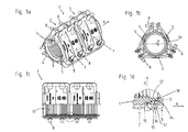
- FIG. 1a shows a seal assembly 1 according to the invention, comprising a first pipe rupture seal 2 and a second pipe rupture seal 3, which in Axially direction A are arranged directly next to each other or one behind the other.
- Each pipe burst seal 2, 3 has a radially encircling, divided into three segments 4, 5, 6 solid 7.
- the individual segments 4, 5, 6 are coupled to one another via screw connections 8.
- an elastic sealing body 9 is arranged on the inside.
- the elastic sealing body 9 has, to recognize well in FIG. 1b which is a front view too FIG. 1a represents, a separating slot 10.
- the separating slot 10 does not extend in the radial direction R, but at an angle thereto.
- the separating slot 10 extends over the axial length of the sealing body 9.
- the sealing body 9 have a sawtooth-shaped inner contour 11, well illustrated in partial sectional view FIG. 1 c.
- FIG Figure 1d The detail of the sealing arrangement 1 according to the invention is shown enlarged in FIG Figure 1d , Good to see here is an extension 12 of the elastic seal body 9 of the first pipe break seal 2, which engages in the axial direction A via an end face 13 protruding into a recess 14 in the elastic sealing body 9 of the second pipe break seal 3. This recess 14 is set back relative to an end face 15 in the axial direction A. Extension 12 and recess 14 are formed in the radial direction on the inside of the sealing body 9.
- a labyrinth seal comprising three circumferential sealing surfaces 16, 17, 18 is produced.
- a first radially encircling sealing surface 16 is at a 90 ° angle to a second radially encircling sealing surface 17, which is oriented in the axial direction A, followed in turn by a third radially encircling sealing surface 18, which is oriented in the radial direction R.
- each pipe rupture seal 2, 3 has an extension 12 on the image plane on a right-hand end side 13 and has a recess 14 on the image plane on the left-hand end side 15. If now these pipe burst seals 2, 3 are moved in the axial direction A, Thus, the extension 12 is positively in the recess 14 to the plant, as in Fig. 1d shown.
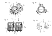
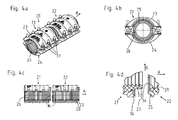
- FIG. 3a to d show a further alternative sealing arrangement 20, comprising in turn a first pipe rupture seal 21 and a second pipe burst seal 22.
- a first pipe rupture seal 21 and a second pipe burst seal 22 are in contrast to the embodiment variant according to FIG. 1 and 2 as in each case radially circumferential only two-part pipe rupture seal 21, 22, comprising a first segment 23 and a second segment 24 is formed.
- an elastic sealing body 25 is arranged radially encircling, which has a separating slot 38.
- an inner circumferential surface 26 is formed with a sawtooth-shaped configuration.
- an extension 27 is also formed here, which projects beyond an end face 28 and engages positively in a recess 29 in the sealing body 25 of the second pipe break sealing clamp 22.
- a labyrinth seal sealing surfaces 30, 31, 32 wherein a first sealing surface 30 and a third sealing surface 31 are oriented in the radial direction R and a second sealing surface 32 is oriented in the axial direction. All sealing surfaces 30, 31, 32 are formed radially encircling.
- a stepped shoulder 35 is formed on a pipe rupture seal 21,22, which by a projection 36 of the first pipe rupture seal 21 in the axial direction A partially positive manner is overrun.
- all the pipe break sealing collars 21, 22 are preferably of the same design, so that not only two, but also three, four or more burst pipe clamps 21, 22 can be arranged directly behind one another in the axial direction A and in each case between the pipe burst sealing collars 21 , 22 and in particular the elastic sealing body 25, a compound according to the invention with overlap of the elastic sealing body 25 is formed.
Landscapes
- Engineering & Computer Science (AREA)
- General Engineering & Computer Science (AREA)
- Mechanical Engineering (AREA)
- Gasket Seals (AREA)
- Pipe Accessories (AREA)
Abstract
Die vorliegende Erfindung betrifft eine Verbindung sowie eine Dichtungsanordnung (1) zwischen zwei Rohrbruchdichtschellen (2, 3; 21, 22), wobei die in den Rohrbruchdichtschellen (2, 3; 21, 22) elastisch angeordneten Dichtungskörper (9, 25) sich in Axialrichtung (A) zumindest abschnittsweise überlappen.The present invention relates to a connection and a seal arrangement (1) between two pipe burst seals (2, 3, 21, 22), wherein in the pipe burst sealing clips (2, 3, 21, 22) elastically arranged sealing body (9, 25) in the axial direction (A) overlap at least in sections.
Description
Die vorliegende Erfindung betrifft eine Verbindung zwischen zwei Rohrbruchdichtschellen gemäß den Merkmalen im Patentanspruch 1.The present invention relates to a connection between two pipe burst sealing clamps according to the features in claim 1.
Die vorliegende Erfindung betrifft weiterhin eine Dichtungsanordnung gemäß den Merkmalen im Oberbegriff von Patentanspruch 2.The present invention further relates to a sealing arrangement according to the features in the preamble of
Zur Versorgung von Gebäuden und Haushalten mit Medien wie beispielsweise Wasser oder Gas ist es aus dem Stand der Technik bekannt, Rohrleitungen insbesondere im Erdreich zu verlegen. Als Rohrleitungen kommen je nach Erstellungsjahr sowie Einsatzort und Einsatzzweck verschiedene Formen von Materialien zur Verwendung. Es gibt Rohrleitungen aus Gusseisen, Stahlwerkstoffen, aus Leichtmetallwerkstofifen, aber auch aus Kunststoff. Die Rohrleitungen haben ferner verschiedene Durchmesser von wenigen Millimetern bis hin zu 80 mm oder gar mehr als 200 mm Durchmesser. Oftmals werden solche Rohrleitungen auch mit der Bezeichnung DN80, DN100, DN150 oder DN200 benannt. Abhängig von dem verwendeten Werkstoff kann es jedoch sein, dass eine solche Rohrleitung mit der Bezeichnung DNxx nicht dem exakten Außendurchmesser der Rohrleitung entspricht, sondern +/- bis zu mehreren Millimetern hinzukommen aufgrund des verschiedenen Werkstoffes. Die nachfolgend beschriebene Erfindung ist bei allen Nennweiten von am Markt befindlichen Nenndurchmessern einsetzbar.For the supply of buildings and households with media such as water or gas, it is known from the prior art to lay piping especially in the ground. Depending on the year of manufacture, location and purpose of use, various forms of materials are used as pipelines. There are piping made of cast iron, steel materials, light metal materials, but also plastic. The pipes have Furthermore, different diameters from a few millimeters up to 80 mm or even more than 200 mm in diameter. Often, such pipelines are also named DN80, DN100, DN150 or DN200. Depending on the material used, however, it may be that such a pipe DNxx does not correspond to the exact outside diameter of the pipe, but added +/- up to several millimeters due to the different material. The invention described below can be used with all nominal diameters of nominal diameters available on the market.
Durch Erdbewegungen, Bauarbeiten oder aber auch alterungsbedingten Verschleiß sowie gegebenenfalls Druckpulsationen des zu fördernden Mediums kann es zu Beschädigungen der Rohrleitungen kommen. Dabei kann eine Rohrleitung derart beschädigt werden, dass ein Riss oder eine Bruchstelle radial zumindest teilweise umlaufend orientiert auftritt. Oftmals treten jedoch gerade Beschädigungen in Form von Rissen oder Bruchstellen auf, die in Axialrichtung der Rohrleitung orientiert sind. Die beschädigte Stelle kann durch ein Messverfahren detektiert werden und das Erdreich wird in diesem Bereich ausgehoben und der entsprechende Abschnitt der Rohrleitung freigelegt.Ground movements, construction work or even aging-related wear and possibly pressure pulsations of the medium to be pumped may cause damage to the pipelines. In this case, a pipeline can be damaged in such a way that a crack or a break occurs radially oriented at least partially circumferentially. Often, however, just happen damage in the form of cracks or breakages, which are oriented in the axial direction of the pipeline. The damaged area can be detected by a measuring method and the soil is excavated in this area and the corresponding section of the pipeline is exposed.
Um diesen Abschnitt der Rohrleitung zumindest temporär zu reparieren, insbesondere abzudichten, sind aus dem Stand der Technik Rohrbruchdichtschellen bekannt. Beispielsweise aus der
Gerade bei Beschädigungen oder Längsrissen, die sich in Axialrichtung orientieren, werden mitunter jedoch Rohrbruchdichtschellen benötigt, die länger sind als 20 cm, 30 cm oder gar 40 cm. Teilweise werden Rohrbruchdichtschellen benötigt, die in Axialrichtung länger sind als 80 cm, 90 cm oder 100 cm. Die die Rohrleitung reparierenden Firmen verwenden dabei Rohrbruchdichtschellen mit einer der Beschädigung entsprechenden axialen Länge. Gerade bei Rohrdurchmessern über 50 mm, insbesondere über 100 mm kann dies jedoch bedeuten, dass eine solche Rohrbruchdichtschelle mehr als 20 kg, insbesondere mehr als 30 kg oder gar mehr als 40 kg wiegt. Eine axiale Verschiebung einer mehr als 50 cm langen Rohrbruchdichtschelle ist aufgrund der Länge, Verschmutzungen auf der Außenseite der beschädigten Rohrleitung sowie des Eigengewichtes nur schwierig oder gar nicht möglich.Especially with damage or longitudinal cracks, which are oriented in the axial direction, but sometimes pipe bursting seals are required, which are longer than 20 cm, 30 cm or even 40 cm. In some cases, pipe burst sealing clamps are required which are longer in the axial direction than 80 cm, 90 cm or 100 cm. The companies repairing the pipeline use pipe burst seals with an axial length corresponding to the damage. Especially with pipe diameters over 50 mm, in particular over 100 mm, however, this may mean that such a pipe burst sealing clamp weighs more than 20 kg, in particular more than 30 kg or even more than 40 kg. An axial displacement of more than 50 cm long pipe break seal is difficult or impossible due to the length, contamination on the outside of the damaged pipe and its own weight.
Aufgabe der vorliegenden Erfindung ist es daher, eine Möglichkeit aufzuzeigen, in einfacher und effektiver Weise beschädigte Rohrleitungen auch über größere axiale Abschnitte abzudichten.Object of the present invention is therefore to show a way to seal in a simple and effective way damaged pipes over larger axial sections.
Die zuvor genannte Aufgabe wird erfindungsgemäß mit einer Verbindung zwischen zwei Rohrbruchdichtschellen mit den Merkmalen im Patentanspruch 1 gelöst.The aforementioned object is achieved with a connection between two pipe break seal clamps with the features in claim 1.
Die zuvor genannte Aufgabe wird weiterhin mit einer Dichtungsanordnung, aufweisend mindestens zwei Rohrbruchdichtschellen, gemäß den Merkmalen im Patentanspruch 2 gelöst.The aforementioned object is further achieved with a sealing arrangement, comprising at least two pipe burst sealing clamps, according to the features in
Vorteilhafte Ausgestaltungsvarianten sind in den abhängigen Patentansprüchen beschrieben.Advantageous embodiments are described in the dependent claims.
Die erfindungsgemäße Verbindung zwischen zwei Rohrbruchdichtschellen, wobei die Rohrbruchdichtschellen in Axialrichtung stirnseitig aneinander angrenzend angeordnet sind und jeweils in einer Rohrbruchdichtschelle ein innenseitig angeordneter elastischer Dichtungskörper angeordnet ist, zeichnet sich dadurch aus, dass sich die Dichtungskörper in Axialrichtung an den Stirnseiten überlappen.The connection according to the invention between two pipe rupture clamps, wherein the pipe rupture clamps are arranged in the axial direction frontally adjacent to each other and arranged in a pipe rupture seal an internally arranged elastic seal body is characterized in that the seal body overlap in the axial direction at the end faces.
Es ist somit erfindungsgemäß möglich, dass zunächst mehrere Rohrbruchdichtschellen durch ein reparierendes Unternehmen bevorratet werden. In Abhängigkeit der in Axialrichtung sich erstreckenden Länge der Beschädigung der Rohrleitung können dann zumindest zwei, bevorzugt aber auch mehrere, beispielsweise drei, vier oder fünf Rohrbruchdichtschellen in Axialrichtung in Reihe direkt hintereinander angeordnet werden. In den Übergangsbereichen, mithin zwischen den Stirnseiten zweier Rohrbruchdichtschellen, kommt es durch die erfindungsgemäße Überlappung der elastischen Dichtungskörper in Axialrichtung zu einer hinreichenden Abdichtung.It is thus possible according to the invention that initially a plurality of broken tube sealing clamps are stored by a repairing company. Depending on the axial length extending length of the damage to the pipeline then at least two, but preferably also several, for example, three, four or five Rohrbruchdichtschellen can be arranged in the axial direction in series directly behind each other. In the transition regions, thus between the end faces of two pipe break sealing clamps, it comes through the inventive overlap of the elastic seal body in the axial direction to a sufficient seal.
Eine solche Verbindung wird weiterhin bei einer erfindungsgemäßen Dichtungsanordnung eingesetzt. Die Dichtungsanordnung für eine Rohrleitung weist mindestens zwei Rohrbruchdichtschellen auf, wobei die Rohrbruchdichtschellen jeweils außenseitig die Rohrleitung umgreifend montierbar sind. Die Rohrbruchdichtschellen zeichnen sich durch einen außenliegenden Festkörper sowie darin angeordnete elastische Dichtungskörper aus. Die Dichtungsanordnung ist erfindungsgemäß dadurch gekennzeichnet, dass ein Dichtungskörper stirnseitig einen radial umlaufenden in Axialrichtung über den Festkörper überstehenden Fortsatz aufweist, wobei der andere Dichtungskörper stirnseitig eine radial umlaufende gegenüber einer Stirnseite des anderen Festkörpers zurückversetzte Ausnehmung aufweist, wobei der Fortsatz formschlüssig und fluiddicht in die Ausnehmung eingreift. Der Fortsatz und die Ausnehmung überlappen sich somit im Bereich des stirnseitigen Angrenzens bzw. Aneinanderliegens der zwei Rohrbruchdichtschellen.Such a connection is further used in a sealing arrangement according to the invention. The seal assembly for a pipe has at least two pipe break sealing clamps, wherein the pipe rupture clamps are each outside the pipe umambend mountable. The pipe rupture clamps are characterized by an outer solid body and arranged therein elastic sealing body. The seal assembly according to the invention is characterized in that a sealing body has a radially encircling axially projecting over the solid protruding extension, wherein the other sealing body has a radially circumferential end face opposite a front side of the other solid recessed recess, wherein the extension positively and fluid-tight in the recess intervenes. The extension and the recess thus overlap in the region of the frontal adjacent or Aneinanderliegens the two pipe break sealing clamps.
Es ist somit möglich, durch Rohrbruchdichtschellen, die beispielsweise eine axiale Erstreckung von 10 cm bis 30 cm aufweisen, diese leicht nach erfolgter Vormontage auf der Rohrleitung zu montieren und bei Bedarf axial zu verschieben. Muss jedoch eine gegenüber einer Rohrbruchdichtschelle längere Bruchstelle oder ein Riss in der Rohrleitung abgedichtet werden, so kann eine zweite Rohrbruchdichtschelle angesetzt werden oder aber vormontiert werden und in Axialrichtung an die bereits angesetzte Rohrbruchdichtschelle geschoben werden. Erfindungsgemäß werden Fortsatz und Ausnehmung der zwei Dichtungskörper überlappend angeordnet, so dass eine Abdichtung erfolgt. Hierzu sind insbesondere der Fortsatz und die Ausnehmung derart ausgebildet, dass eine Labyrinthdichtung ausgebildet wird. Durch die Montage, insbesondere ein Festziehen, wodurch eine Verringerung des Durchmessers der Rohrbruchdichtschelle auch an der Seite der Ausnehmung erfolgt, werden Ausnehmung und Fortsatz auf die Radialrichtung bezogen, jedoch auch zumindest teilweise in Axialrichtung, formschlüssig unter Spannung gebracht, so dass diese fluiddicht aneinander anliegen.It is thus possible, by pipe rupture clamps, for example, have an axial extent of 10 cm to 30 cm, these easy to install after the pre-assembly on the pipeline and move it axially if necessary. However, if a fracture point or a crack in the pipeline which is longer than a pipe burst seal is to be sealed, then a second pipe burst seal can be applied or can be preassembled and pushed in the axial direction against the already installed pipe burst seal. According extension and recess of the two sealing body are arranged overlapping, so that a seal is made. For this purpose, in particular the extension and the recess are formed such that a labyrinth seal is formed. Through the assembly, in particular a tightening, whereby a reduction in the diameter of the pipe rupture seal also takes place on the side of the recess, recess and extension are based on the radial direction, but also at least partially brought in the axial direction, positively under tension, so that they abut each other in a fluid-tight manner ,
Die elastischen Dichtungskörper sind insbesondere aus einem gummiartigen Werkstoff bzw. einem Elastomerwerkstoff ausgebildet. Die Dichtungskörper sind insbesondere als Dichtungshülse bzw. Dichtungsmanschette einstückig und werkstoffeinheitlich ausgebildet. Bevorzugt weisen diese eine Trennfuge bzw. Trennschlitz auf, so dass der Dichtungskörper seitlich auf die Rohrleitung zur Montage bzw. Vormontage aufgesetzt werden kann. Der aufgesetzte Dichtungskörper umgreift dann die Rohrleitung. Die Trennfuge durchtrennt den Dichtungskörper in Radialrichtung und erstreckt sich über die axiale Länge des Dichtungskörpers.The elastic sealing bodies are in particular formed from a rubber-like material or an elastomer material. The sealing body are in particular formed as a sealing sleeve or gasket in one piece and material uniform. Preferably, these have a parting line or separating slot, so that the sealing body can be placed laterally on the pipeline for assembly or pre-assembly. The attached seal body then surrounds the pipeline. The parting line cuts through the sealing body in the radial direction and extends over the axial length of the sealing body.
Der Festkörper selbst ist bevorzugt aus einem metallischen Werkstoff ausgebildet, insbesondere aus einem Gusswerkstoff. Bevorzugt ist der Festkörper radial umlaufend zweiteilig und ganz besonders bevorzugt dreiteilig ausgebildet mit einzelnen Segmenten. Die Segmente sind formschlüssig miteinander gekoppelt, insbesondere über Verschraubungen, wobei die Verschraubungen angezogen werden, insbesondere mit einem vorgegebenen Drehmoment. Hierdurch kann ein entsprechender Anpressdruck auf den in Radialrichtung unterhalb des Festkörpers befindlichen Dichtungskörper aufgebracht werden, der wiederum zu einer Abdichtung der Rohrleitung führt.The solid itself is preferably formed of a metallic material, in particular of a cast material. Preferably, the solid body is radially surrounding two parts and most preferably three-part design with individual segments. The segments are positively coupled to each other, in particular via screw, wherein the fittings are tightened, in particular with a predetermined torque. In this way, a corresponding contact pressure can be applied to the sealing body located in the radial direction below the solid body, which in turn leads to a sealing of the pipeline.
In besonders bevorzugter Ausgestaltungsvariante sind die Festkörper, insbesondere die Segmente des Festkörpers, mit dem Dichtungskörper gekoppelt. Beispielsweise können diese auf den Dichtungskörper aufgeklebt sein. Es ist jedoch auch möglich, dass die Segmente auf den Dichtungskörper aufvulkanisiert sind.In a particularly preferred embodiment variant, the solids, in particular the segments of the solid, are coupled to the sealing body. For example, these may be glued to the seal body. However, it is also possible that the segments are vulcanized onto the sealing body.
An einer sich in Axialrichtung erstreckenden Trennstelle von zwei Segmenten des radial umlaufenden Festkörpers ist ein Blechstreifen auf der Außenseite des Dichtungskörpers angeordnet, insbesondere einvulkanisiert oder in ausgeformten Bereichen eingeklebt, so dass bei Festziehen der Verschraubung sich der Dichtungskörper nicht radial nach außen ausdehnt und/oder zwischen zwei Segmenten eingeklemmt wird.At an axially extending separation point of two segments of the radially rotating solid body, a sheet metal strip is arranged on the outside of the seal body, in particular vulcanized or in formed Glued areas so that when tightening the screw, the seal body does not expand radially outward and / or is clamped between two segments.
Alternativ oder ergänzend sind an den Segmenten zahnartige Fortsätze ausgebildet, wobei die zahnartigen Fortsätze zweier Segmente kammartig ineinandergreifen. Die zahnartigen Fortsätze haben dann eine Innenkontur, welche eine Fortsetzung des Innenradius des Segmentes ist. Durch die zahnartig ineinander kämmenden Fortsätze zweier Segmente wird ebenfalls ein radiales Ausdehnen des elastischen Dichtungskörpers bei Festziehen der Rohrbruchdichtschelle vermieden.Alternatively or additionally, tooth-like projections are formed on the segments, the tooth-like extensions of two segments meshing in a comb-like manner. The tooth-like extensions then have an inner contour, which is a continuation of the inner radius of the segment. By the tooth-like intermeshing extensions of two segments also a radial expansion of the elastic sealing body is avoided when tightening the pipe burst seal.
Besonders bevorzugt ist die Dichtungsanordnung als System ausgebildet, so dass eine Rohrbruchdichtschelle auf einer Seite stirnseitig den Fortsatz aufweist und auf der gegenüberliegenden Stirnseite der gleichen Rohrbruchdichtschelle die Ausnehmung. Es ist somit möglich, mehr als zwei, insbesondere mehr als drei, mithin beliebig viele Rohrbruchdichtschellen in Axialrichtung hintereinander auf der Rohrleitung anzuordnen. Somit kann einem jeweiligen Reparaturdienst durch die Bereitstellung entweder von Rohrbruchdichtschellen mit einheitlicher Gesamtlänge oder aber mehreren Rohrbruchdichtschellen in verschiedenen Längen die Möglichkeit gegeben werden, eine Beschädigung der Rohrleitung abzudichten, wobei eine entsprechend beschädigte Stelle in Axialrichtung länger ist als die längste in dem System vorhandene Rohrbruchdichtschelle. Bei einem Riss, beispielsweise von 50 cm Erstreckung in Axialrichtung der Rohrleitung, muss nicht eine für diesen Einsatzzweck vorgesehene Rohrbruchdichtschelle verwendet werden, die beispielsweise eine Länge in Axialrichtung von 60 cm aufweist. Es können beispielsweise drei Rohrbruchdichtschellen von 20 cm oder zwei Rohrbruchdichtschellen von 30 cm zur Abdichtung des Risses angesetzt und montiert werden.Particularly preferably, the seal assembly is formed as a system, so that a pipe rupture clamp on one side has the front side of the extension and on the opposite end face of the same pipe break seal the recess. It is thus possible to arrange more than two, in particular more than three, thus any number of pipe breakage sealing clamps in the axial direction one behind the other on the pipeline. Thus, a particular repair service can be given the ability to seal damage to the tubing by providing either single-length burst pipe clamps or multiple burst pipe clamps of various lengths, with a correspondingly damaged location in the axial direction being longer than the longest burst pipe seal in the system. In a crack, for example, 50 cm extension in the axial direction of the pipeline, not a tube intended for this purpose pipe burst seal must be used, for example, has a length in the axial direction of 60 cm. For example, it is possible to attach and install three 20 cm burst pipe clamps or two 30 cm burst pipe clamps to seal the crack.
Damit die Dichtungswirkung auch bei eventuell in der Praxis auftretender unzweckmäßiger Montage bestmöglich ausgebildet ist, sind bevorzugt zwischen dem Fortsatz und der Ausnehmung mindestens zwei Anlageflächen, auch als Dichtflächen bezeichnet, bevorzugt drei Anlageflächen ausgebildet. Die mindestens zwei Anlageflächen stehen in einem Winkel zueinander und verlaufen jeweils radial umlaufend, insbesondere weist der Winkel 90° auf. Insbesondere ist hier zumindest eine Anlagefläche in Radialrichtung orientiert verlaufend und eine zweite Anlagefläche in einem Winkel dazu verlaufend angeordnet, besonders bevorzugt ist die zweite Anlagefläche in Axialrichtung orientiert radial umlaufend zwischen Fortsatz und Ausnehmung ausgebildet. Eine dritte Anlagefläche kann wiederum in Radialrichtung orientiert radial umlaufend ausgebildet sein. Die axial orientierte Anlagefläche bietet dabei den Vorteil, dass bei Anziehen der Verschraubung des Festkörpers durch die damit einhergehende radiale Komprimierung eine Flächenpressung von Fortsatz und Ausnehmung ausgebildet wird. Dies hat aufgrund der Elastizität des Dichtungskörpers jedoch auch gleichsam die Wirkung, dass zumindest nicht nur die Flächenpressung erhöht wird, sondern auch eine Ausdehnung in Axialrichtung erzeugt wird. Durch die in Radialrichtung orientierte umlaufende Dichtfläche kommt es hier aufgrund der axialen Ausdehnung wiederum zu einer formschlüssigen fluiddichten Anlage.In order for the sealing effect to be optimally formed even in the event of inappropriate application occurring in practice, at least two contact surfaces, also referred to as sealing surfaces, are preferably formed between the extension and the recess, preferably three contact surfaces. The at least two contact surfaces are at an angle to each other and each extend radially circumferential, in particular, the angle to 90 °. In particular, here at least one contact surface is oriented in the radial direction and a second contact surface is arranged at an angle thereto, particularly preferably the second contact surface is oriented in the axial direction, formed radially circumferentially between the extension and the recess. A third abutment surface can in turn be designed so as to be oriented radially in the radial direction. The axially oriented bearing surface offers the advantage that when tightening the screw of the solid by the associated radial compression surface pressure of extension and recess is formed. However, due to the elasticity of the sealing body, this also has the effect, as it were, of at least not only increasing the surface pressure, but also generating an expansion in the axial direction. Due to the axial expansion, the radially oriented circumferential sealing surface again results in a form-fitting, fluid-tight installation.
Bevorzugt sind Ausnehmung und Fortsatz, auf die Radialrichtung bezogen, an dem jeweiligen Dichtungskörper innenliegend ausgebildet. Der Fortsatz liegt somit bevorzugt an dem Rohr an und erstreckt sich in Axialrichtung. Der Fortsatz und die Ausnehmung können jedoch auch, auf die Radialrichtung bezogen, mittig an bzw. in dem Dichtungskörper ausgebildet sein oder aber außenliegend.Preferably, recess and extension, relative to the radial direction, formed on the respective sealing body on the inside. The extension is thus preferably on the tube and extends in the axial direction. However, the extension and the recess may also, in the radial direction, be formed centrally on or in the seal body or outboard.
Um die Dichtungswirkung weiter zu steigern, ist es besonders bevorzugt vorgesehen, dass in der axialen Anlagefläche zwischen Fortsatz und Ausnehmung mindestens eine formschlüssige Geometrie ausgebildet ist. Die formschlüssige Geometrie ist bevorzugt eine Erhebung, die korrespondierend in eine Einmuldung eingreift. Die Erhebung kann dabei eine an dem Fortsatz, auf die Radialrichtung bezogen, nach außen gerichtete Erhebung sein, die in eine Einmuldung der Ausnehmung formschlüssig eingreift.In order to increase the sealing effect further, it is particularly preferably provided that at least one positive-locking geometry is formed in the axial bearing surface between extension and recess. The positive-locking geometry is preferably an elevation which correspondingly engages in one's imputation. In this case, the elevation may be an elevation, which is directed towards the outside relative to the extension, in the radial direction, which engages in a positive manner into a recess of the recess.
Weiterhin besonders bevorzugt ist es vorgesehen, dass an der Stirnseite des Fortsatzes der Festkörper radial abschnittsweise umlaufend mindestens einen, bevorzugt zwei oder mehrere Überstände aufweist. An einer zweiten Rohrbruchdichtschelle ist an der Stirnseite der Ausnehmung ein Stufenabsatz ausgebildet. Der oder die Überstände der ersten Rohrbruchdichtschelle übergreifen dabei in Axialrichtung den Stufenabsatz der zweiten Rohrbruchdichtschelle. Hierdurch wird einem anwendenden Monteur die Möglichkeit gegeben, den korrekten Sitz der zwei in Axialrichtung hintereinander angeordneten Rohrbruchdichtschellen zu überprüfen. Übergreift der Überstand den Stufenabsatz zumindest abschnittsweise in Axialrichtung, so ist auch der Fortsatz des ersten Dichtungskörpers ordnungsgemäß in die Ausnehmung des zweiten Dichtungskörpers eingreifend angeordnet.Further particularly preferably, it is provided that on the end face of the extension of the solid body radially circumferentially circumferentially at least one, preferably two or more supernatants. At a second pipe rupture seal a stepped shoulder is formed on the end face of the recess. The one or more projections overlap the first pipe burst seal while in the axial direction of the stepped shoulder of the second pipe break seal. As a result, an applying installer is given the opportunity to check the correct fit of the two axially arranged in succession pipe burst sealing clamps. If the projection overlaps the stepped shoulder at least in sections in the axial direction, then the extension of the first sealing body is also arranged to engage properly in the recess of the second sealing body.
In einer weiteren möglichen Ausgestaltungsvariante kann auch eine formschlüssige Verbindung zweier in Axialrichtung hintereinander angeordneter Festkörper erfolgen, beispielsweise nach Art eines Nut- und Federsystems erfolgen.In a further possible embodiment variant, a positive connection between two axially successively arranged solid can be done, for example, done in the manner of a tongue and groove system.
Weitere Vorteile, Merkmale, Eigenschaften und Aspekte der vorliegenden Erfindung sind Gegenstand der nachfolgenden Beschreibung. Bevorzugte Ausgestaltungsvarianten werden in den schematischen Figuren dargestellt. Diese dienen dem einfachen Verständnis der Erfindung. Es zeigen:
- Figur 1a bis d
- eine erfindungsgemäße Dichtungsanordnung, aufweisend zwei Rohrbruchdichtschellen in Axialrichtung direkt hintereinander in verschiedenen Ansichten und Detailansicht,
- Figur 2a bis d
- die Rohrbruchdichtschellen gemäß
Figur 1 , jedoch in Axialrichtung voneinander entfernt angeordnet, - Figur 3a bis d
- eine alternative Ausgestaltungsvariante einer Dichtungsanordnung mit jeweils zweigeteilten Rohrbruchdichtschellen und
- Figur 4a bis d
- die
Dichtungsanordnung aus Figur 3 in Axialrichtung voneinander beabstandet.
- FIGS. 1a to d
- a seal assembly according to the invention, comprising two pipe burst seals in the axial direction directly behind one another in different views and detail view,
- FIGS. 2a to d
- the pipe burst seals according to
FIG. 1 but arranged away from each other in the axial direction, - FIG. 3a to d
- an alternative embodiment variant of a seal assembly, each with two-part pipe rupture clamps and
- FIGS. 4a to d
- the seal arrangement
FIG. 3 spaced apart in the axial direction.
In den Figuren werden für gleiche oder ähnliche Bauteile dieselben Bezugszeichen verwendet, auch wenn eine wiederholte Beschreibung aus Vereinfachungsgründen entfällt.In the figures, the same reference numerals are used for the same or similar components, even if a repeated description is omitted for reasons of simplicity.
Das erfindungsgemäße Detail der Dichtungsanordnung 1 ist vergrößert dargestellt in
Durch die Überlappung von Fortsatz 12 und Ausnehmung 14 wird eine Labyrinthdichtung, aufweisend drei umlaufende Dichtflächen 16, 17, 18 hergestellt. Eine erste radial umlaufende Dichtfläche 16 steht in einem 90° Winkel zu einer zweiten radial umlaufenden Dichtfläche 17, welche in Axialrichtung A orientiert ist, gefolgt wiederum von einer dritten radial umlaufenden Dichtfläche 18, welche in Radialrichtung R orientiert ist.Due to the overlap of
Dargestellt ist dies nochmals in
Gemäß
Ferner ist gemäß
- 1 -1 -
- Dichtungsanordnungsealing arrangement
- 2 -2 -
- erste Rohrbruchdichtschellefirst pipe break seal
- 3 -3 -
- zweite Rohrbruchdichtschellesecond pipe burst seal
- 4 -4 -
- Segmentsegment
- 5 -5 -
- Segmentsegment
- 6 -6 -
- Segmentsegment
- 7 -7 -
- Festkörpersolid
- 8 -8th -
- Schraubverbindungscrew
- 9 -9 -
- elastischer Dichtungskörperelastic sealing body
- 10 -10 -
- Trennschlitzseparating slot
- 11 -11 -
- Innenkonturinner contour
- 12 -12 -
- Fortsatzextension
- 13 -13 -
- Stirnseite zu 2Front side to 2
- 14 -14 -
- Ausnehmungrecess
- 15 -15 -
- Stirnseite zu 3Front side to 3
- 16 -16 -
- erste Dichtflächefirst sealing surface
- 17 -17 -
- zweite Dichtflächesecond sealing surface
- 18 -18 -
- dritte Dichtflächethird sealing surface
- 20 -20 -
- Dichtungsanordnungsealing arrangement
- 21 -21 -
- erste Rohrbruchdichtschellefirst pipe break seal
- 22 -22 -
- zweite Rohrbruchdichtschellesecond pipe burst seal
- 23 -23 -
- erstes Segmentfirst segment
- 24 -24 -
- zweites Segmentsecond segment
- 25 -25 -
- elastischer Dichtungskörperelastic sealing body
- 26 -26 -
- InnenmantelflächeInner surface area
- 27 -27 -
- Fortsatzextension
- 28 -28 -
- Stirnseitefront
- 29 -29 -
- Ausnehmungrecess
- 30 -30 -
- erste Dichtflächefirst sealing surface
- 31 -31 -
- dritte Dichtflächethird sealing surface
- 32 -32 -
- zweite Dichtflächesecond sealing surface
- 33 -33 -
- EinmuldungEinmuldung
- 34 -34 -
- Erhebungsurvey
- 35 -35 -
- Stufenabsatzstepped shoulder
- 36 -36 -
- ÜberstandGot over
- 37 -37 -
- Schraubverbindungscrew
- 38 -38 -
- Trennschlitz zu 25Separating slot to 25
- A -A -
- Axialrichtungaxially
- R -R -
- Radialrichtungradial direction
Claims (9)
Priority Applications (1)
| Application Number | Priority Date | Filing Date | Title |
|---|---|---|---|
| PL16192862T PL3165804T3 (en) | 2015-11-04 | 2016-10-07 | Connection of two pipe break seal ring and sealing assembly |
Applications Claiming Priority (1)
| Application Number | Priority Date | Filing Date | Title |
|---|---|---|---|
| DE102015118870.8A DE102015118870A1 (en) | 2015-11-04 | 2015-11-04 | Connection of two pipe burst seals and seal arrangement |
Publications (2)
| Publication Number | Publication Date |
|---|---|
| EP3165804A1 true EP3165804A1 (en) | 2017-05-10 |
| EP3165804B1 EP3165804B1 (en) | 2017-11-29 |
Family
ID=57113203
Family Applications (1)
| Application Number | Title | Priority Date | Filing Date |
|---|---|---|---|
| EP16192862.7A Active EP3165804B1 (en) | 2015-11-04 | 2016-10-07 | Connection of two pipe break seal ring and sealing assembly |
Country Status (8)
| Country | Link |
|---|---|
| EP (1) | EP3165804B1 (en) |
| DE (2) | DE102015118870A1 (en) |
| DK (1) | DK3165804T3 (en) |
| ES (1) | ES2654149T3 (en) |
| HU (1) | HUE036263T2 (en) |
| NO (1) | NO3165804T3 (en) |
| PL (1) | PL3165804T3 (en) |
| PT (1) | PT3165804T (en) |
Citations (6)
| Publication number | Priority date | Publication date | Assignee | Title |
|---|---|---|---|---|
| US3298698A (en) * | 1964-04-27 | 1967-01-17 | Owens Illinois Glass Co | Pipe coupling for joining pipe sections of varying size |
| DE1966014U (en) | 1967-05-06 | 1967-08-10 | Kurt Melcher Fa | PIPE SEAL CLAMP. |
| FR2081022A1 (en) * | 1970-02-20 | 1971-11-26 | Corning Glass Works | |
| DE7519851U (en) | 1975-06-23 | 1975-11-13 | Rva Doering Kg | PIPE SEALING CLAMP |
| DE8429896U1 (en) | 1984-10-11 | 1985-01-10 | Melcher & Frenzen Armaturen GmbH & Co KG, 5620 Velbert | PIPE SEALING CLAMP |
| US20130255816A1 (en) * | 2012-03-30 | 2013-10-03 | Oceaneering International, Inc. | Chained Clamp Pipeline Repair Structure and Method of Use |
Family Cites Families (1)
| Publication number | Priority date | Publication date | Assignee | Title |
|---|---|---|---|---|
| DE7541871U (en) * | 1975-12-31 | 1976-08-05 | Blom, Dietrich, 4650 Gelsenkirchen | CLAMP FOR PIPING |
-
2015
- 2015-11-04 DE DE102015118870.8A patent/DE102015118870A1/en not_active Withdrawn
-
2016
- 2016-10-07 NO NO16192862A patent/NO3165804T3/no unknown
- 2016-10-07 HU HUE16192862A patent/HUE036263T2/en unknown
- 2016-10-07 PT PT161928627T patent/PT3165804T/en unknown
- 2016-10-07 DE DE202016105617.9U patent/DE202016105617U1/en active Active
- 2016-10-07 EP EP16192862.7A patent/EP3165804B1/en active Active
- 2016-10-07 PL PL16192862T patent/PL3165804T3/en unknown
- 2016-10-07 DK DK16192862.7T patent/DK3165804T3/en active
- 2016-10-07 ES ES16192862.7T patent/ES2654149T3/en active Active
Patent Citations (6)
| Publication number | Priority date | Publication date | Assignee | Title |
|---|---|---|---|---|
| US3298698A (en) * | 1964-04-27 | 1967-01-17 | Owens Illinois Glass Co | Pipe coupling for joining pipe sections of varying size |
| DE1966014U (en) | 1967-05-06 | 1967-08-10 | Kurt Melcher Fa | PIPE SEAL CLAMP. |
| FR2081022A1 (en) * | 1970-02-20 | 1971-11-26 | Corning Glass Works | |
| DE7519851U (en) | 1975-06-23 | 1975-11-13 | Rva Doering Kg | PIPE SEALING CLAMP |
| DE8429896U1 (en) | 1984-10-11 | 1985-01-10 | Melcher & Frenzen Armaturen GmbH & Co KG, 5620 Velbert | PIPE SEALING CLAMP |
| US20130255816A1 (en) * | 2012-03-30 | 2013-10-03 | Oceaneering International, Inc. | Chained Clamp Pipeline Repair Structure and Method of Use |
Also Published As
| Publication number | Publication date |
|---|---|
| HUE036263T2 (en) | 2018-06-28 |
| DE102015118870A1 (en) | 2017-05-04 |
| EP3165804B1 (en) | 2017-11-29 |
| DE202016105617U1 (en) | 2016-10-25 |
| PT3165804T (en) | 2018-01-04 |
| DK3165804T3 (en) | 2018-01-08 |
| NO3165804T3 (en) | 2018-04-28 |
| ES2654149T3 (en) | 2018-02-12 |
| PL3165804T3 (en) | 2018-03-30 |
Similar Documents
| Publication | Publication Date | Title |
|---|---|---|
| DE60320226T2 (en) | ANCHORING DEVICE FOR PIPE COUPLING | |
| EP2479469B1 (en) | Connection assembly and method for producing same | |
| DE102007026394A1 (en) | Tight hose connection | |
| EP3428498B1 (en) | Pipe, in particular plastic pipe for drain pipes | |
| EP2703707B1 (en) | System for producing a fluid-tight pipe connection | |
| DE102016120436A1 (en) | Seal arrangement | |
| AT508386A4 (en) | DEVICE FOR CONNECTING WATER PIPES | |
| EP2933542A1 (en) | Connection for corrugated pipes | |
| DE102017105858A1 (en) | pipe coupling | |
| EP2194305B1 (en) | Flange connections for pipes | |
| DE102010016972A1 (en) | Connection for a pipe | |
| EP2133613A2 (en) | Connection element and attachment, in particular for connecting solar collectors | |
| DE202007010592U1 (en) | Arrangement for fastening a line with a profiled outside diameter | |
| DE102008063296A1 (en) | Method for producing a loose flange and fitting with at least one pipe section and with a loose flange | |
| EP3165804B1 (en) | Connection of two pipe break seal ring and sealing assembly | |
| EP3683481B1 (en) | Fitting and extension piece for pipelines | |
| DE102014111691B4 (en) | Sealing arrangement on a building wall | |
| DE102010009618B4 (en) | Connection device for a modular installation system | |
| EP2672159A1 (en) | Device for attaching a tube to a connection nipple | |
| DE202009015214U1 (en) | Wellrohrkompensator | |
| DE102017103433A1 (en) | Pipe fitting for metallic pipes | |
| DE102015226513A1 (en) | Kit for a pipe connection and sealing ring for such a pipe connection | |
| DE102014111693A1 (en) | Sealing arrangement with split plastic flange | |
| DE10118738B4 (en) | Flange seal for a flange, in particular for pipes or fittings and fittings with spigot ends | |
| EP2754938B1 (en) | Assembled product comprising a screw nipple and a threaded bushing, and an associated hydraulic system |
Legal Events
| Date | Code | Title | Description |
|---|---|---|---|
| PUAI | Public reference made under article 153(3) epc to a published international application that has entered the european phase |
Free format text: ORIGINAL CODE: 0009012 |
|
| 17P | Request for examination filed |
Effective date: 20170315 |
|
| AK | Designated contracting states |
Kind code of ref document: A1 Designated state(s): AL AT BE BG CH CY CZ DE DK EE ES FI FR GB GR HR HU IE IS IT LI LT LU LV MC MK MT NL NO PL PT RO RS SE SI SK SM TR |
|
| AX | Request for extension of the european patent |
Extension state: BA ME |
|
| GRAP | Despatch of communication of intention to grant a patent |
Free format text: ORIGINAL CODE: EPIDOSNIGR1 |
|
| INTG | Intention to grant announced |
Effective date: 20170802 |
|
| GRAS | Grant fee paid |
Free format text: ORIGINAL CODE: EPIDOSNIGR3 |
|
| GRAA | (expected) grant |
Free format text: ORIGINAL CODE: 0009210 |
|
| AK | Designated contracting states |
Kind code of ref document: B1 Designated state(s): AL AT BE BG CH CY CZ DE DK EE ES FI FR GB GR HR HU IE IS IT LI LT LU LV MC MK MT NL NO PL PT RO RS SE SI SK SM TR |
|
| REG | Reference to a national code |
Ref country code: CH Ref legal event code: EP |
|
| REG | Reference to a national code |
Ref country code: AT Ref legal event code: REF Ref document number: 950710 Country of ref document: AT Kind code of ref document: T Effective date: 20171215 |
|
| REG | Reference to a national code |
Ref country code: IE Ref legal event code: FG4D Free format text: LANGUAGE OF EP DOCUMENT: GERMAN |
|
| REG | Reference to a national code |
Ref country code: DE Ref legal event code: R096 Ref document number: 502016000321 Country of ref document: DE Ref country code: PT Ref legal event code: SC4A Ref document number: 3165804 Country of ref document: PT Date of ref document: 20180104 Kind code of ref document: T Free format text: AVAILABILITY OF NATIONAL TRANSLATION Effective date: 20171227 |
|
| REG | Reference to a national code |
Ref country code: DK Ref legal event code: T3 Effective date: 20180105 |
|
| REG | Reference to a national code |
Ref country code: NL Ref legal event code: FP |
|
| REG | Reference to a national code |
Ref country code: SE Ref legal event code: TRGR |
|
| REG | Reference to a national code |
Ref country code: ES Ref legal event code: FG2A Ref document number: 2654149 Country of ref document: ES Kind code of ref document: T3 Effective date: 20180212 |
|
| REG | Reference to a national code |
Ref country code: NO Ref legal event code: T2 Effective date: 20171129 |
|
| REG | Reference to a national code |
Ref country code: LT Ref legal event code: MG4D |
|
| PG25 | Lapsed in a contracting state [announced via postgrant information from national office to epo] |
Ref country code: FI Free format text: LAPSE BECAUSE OF FAILURE TO SUBMIT A TRANSLATION OF THE DESCRIPTION OR TO PAY THE FEE WITHIN THE PRESCRIBED TIME-LIMIT Effective date: 20171129 Ref country code: LT Free format text: LAPSE BECAUSE OF FAILURE TO SUBMIT A TRANSLATION OF THE DESCRIPTION OR TO PAY THE FEE WITHIN THE PRESCRIBED TIME-LIMIT Effective date: 20171129 |
|
| PG25 | Lapsed in a contracting state [announced via postgrant information from national office to epo] |
Ref country code: HR Free format text: LAPSE BECAUSE OF FAILURE TO SUBMIT A TRANSLATION OF THE DESCRIPTION OR TO PAY THE FEE WITHIN THE PRESCRIBED TIME-LIMIT Effective date: 20171129 Ref country code: BG Free format text: LAPSE BECAUSE OF FAILURE TO SUBMIT A TRANSLATION OF THE DESCRIPTION OR TO PAY THE FEE WITHIN THE PRESCRIBED TIME-LIMIT Effective date: 20180228 Ref country code: LV Free format text: LAPSE BECAUSE OF FAILURE TO SUBMIT A TRANSLATION OF THE DESCRIPTION OR TO PAY THE FEE WITHIN THE PRESCRIBED TIME-LIMIT Effective date: 20171129 Ref country code: RS Free format text: LAPSE BECAUSE OF FAILURE TO SUBMIT A TRANSLATION OF THE DESCRIPTION OR TO PAY THE FEE WITHIN THE PRESCRIBED TIME-LIMIT Effective date: 20171129 |
|
| REG | Reference to a national code |
Ref country code: HU Ref legal event code: AG4A Ref document number: E036263 Country of ref document: HU |
|
| PG25 | Lapsed in a contracting state [announced via postgrant information from national office to epo] |
Ref country code: CY Free format text: LAPSE BECAUSE OF FAILURE TO SUBMIT A TRANSLATION OF THE DESCRIPTION OR TO PAY THE FEE WITHIN THE PRESCRIBED TIME-LIMIT Effective date: 20171129 Ref country code: EE Free format text: LAPSE BECAUSE OF FAILURE TO SUBMIT A TRANSLATION OF THE DESCRIPTION OR TO PAY THE FEE WITHIN THE PRESCRIBED TIME-LIMIT Effective date: 20171129 Ref country code: SK Free format text: LAPSE BECAUSE OF FAILURE TO SUBMIT A TRANSLATION OF THE DESCRIPTION OR TO PAY THE FEE WITHIN THE PRESCRIBED TIME-LIMIT Effective date: 20171129 |
|
| REG | Reference to a national code |
Ref country code: DE Ref legal event code: R097 Ref document number: 502016000321 Country of ref document: DE |
|
| PG25 | Lapsed in a contracting state [announced via postgrant information from national office to epo] |
Ref country code: SM Free format text: LAPSE BECAUSE OF FAILURE TO SUBMIT A TRANSLATION OF THE DESCRIPTION OR TO PAY THE FEE WITHIN THE PRESCRIBED TIME-LIMIT Effective date: 20171129 Ref country code: IT Free format text: LAPSE BECAUSE OF FAILURE TO SUBMIT A TRANSLATION OF THE DESCRIPTION OR TO PAY THE FEE WITHIN THE PRESCRIBED TIME-LIMIT Effective date: 20171129 |
|
| PG25 | Lapsed in a contracting state [announced via postgrant information from national office to epo] |
Ref country code: MT Free format text: LAPSE BECAUSE OF FAILURE TO SUBMIT A TRANSLATION OF THE DESCRIPTION OR TO PAY THE FEE WITHIN THE PRESCRIBED TIME-LIMIT Effective date: 20171129 |
|
| PLBE | No opposition filed within time limit |
Free format text: ORIGINAL CODE: 0009261 |
|
| STAA | Information on the status of an ep patent application or granted ep patent |
Free format text: STATUS: NO OPPOSITION FILED WITHIN TIME LIMIT |
|
| REG | Reference to a national code |
Ref country code: FR Ref legal event code: PLFP Year of fee payment: 3 |
|
| 26N | No opposition filed |
Effective date: 20180830 |
|
| PG25 | Lapsed in a contracting state [announced via postgrant information from national office to epo] |
Ref country code: MC Free format text: LAPSE BECAUSE OF FAILURE TO SUBMIT A TRANSLATION OF THE DESCRIPTION OR TO PAY THE FEE WITHIN THE PRESCRIBED TIME-LIMIT Effective date: 20171129 |
|
| PG25 | Lapsed in a contracting state [announced via postgrant information from national office to epo] |
Ref country code: TR Free format text: LAPSE BECAUSE OF FAILURE TO SUBMIT A TRANSLATION OF THE DESCRIPTION OR TO PAY THE FEE WITHIN THE PRESCRIBED TIME-LIMIT Effective date: 20171129 |
|
| PG25 | Lapsed in a contracting state [announced via postgrant information from national office to epo] |
Ref country code: GR Free format text: LAPSE BECAUSE OF FAILURE TO SUBMIT A TRANSLATION OF THE DESCRIPTION OR TO PAY THE FEE WITHIN THE PRESCRIBED TIME-LIMIT Effective date: 20171129 Ref country code: MK Free format text: LAPSE BECAUSE OF NON-PAYMENT OF DUE FEES Effective date: 20171129 Ref country code: RO Free format text: LAPSE BECAUSE OF FAILURE TO SUBMIT A TRANSLATION OF THE DESCRIPTION OR TO PAY THE FEE WITHIN THE PRESCRIBED TIME-LIMIT Effective date: 20171129 |
|
| PG25 | Lapsed in a contracting state [announced via postgrant information from national office to epo] |
Ref country code: AL Free format text: LAPSE BECAUSE OF FAILURE TO SUBMIT A TRANSLATION OF THE DESCRIPTION OR TO PAY THE FEE WITHIN THE PRESCRIBED TIME-LIMIT Effective date: 20171129 Ref country code: IS Free format text: LAPSE BECAUSE OF FAILURE TO SUBMIT A TRANSLATION OF THE DESCRIPTION OR TO PAY THE FEE WITHIN THE PRESCRIBED TIME-LIMIT Effective date: 20180329 |
|
| PG25 | Lapsed in a contracting state [announced via postgrant information from national office to epo] |
Ref country code: SI Free format text: LAPSE BECAUSE OF NON-PAYMENT OF DUE FEES Effective date: 20181007 |
|
| PGFP | Annual fee paid to national office [announced via postgrant information from national office to epo] |
Ref country code: PT Payment date: 20220929 Year of fee payment: 7 |
|
| PGFP | Annual fee paid to national office [announced via postgrant information from national office to epo] |
Ref country code: NL Payment date: 20221019 Year of fee payment: 7 Ref country code: FR Payment date: 20221031 Year of fee payment: 7 |
|
| PGFP | Annual fee paid to national office [announced via postgrant information from national office to epo] |
Ref country code: SE Payment date: 20221019 Year of fee payment: 7 Ref country code: NO Payment date: 20221021 Year of fee payment: 7 Ref country code: IE Payment date: 20221020 Year of fee payment: 7 Ref country code: ES Payment date: 20221222 Year of fee payment: 7 Ref country code: DK Payment date: 20221021 Year of fee payment: 7 Ref country code: CZ Payment date: 20220930 Year of fee payment: 7 |
|
| PGFP | Annual fee paid to national office [announced via postgrant information from national office to epo] |
Ref country code: PL Payment date: 20221003 Year of fee payment: 7 Ref country code: HU Payment date: 20221016 Year of fee payment: 7 Ref country code: BE Payment date: 20221019 Year of fee payment: 7 |
|
| PGFP | Annual fee paid to national office [announced via postgrant information from national office to epo] |
Ref country code: LU Payment date: 20231019 Year of fee payment: 8 |
|
| PGFP | Annual fee paid to national office [announced via postgrant information from national office to epo] |
Ref country code: GB Payment date: 20231020 Year of fee payment: 8 |
|
| PGFP | Annual fee paid to national office [announced via postgrant information from national office to epo] |
Ref country code: DE Payment date: 20231030 Year of fee payment: 8 Ref country code: CH Payment date: 20231102 Year of fee payment: 8 Ref country code: AT Payment date: 20231020 Year of fee payment: 8 |
|
| PG25 | Lapsed in a contracting state [announced via postgrant information from national office to epo] |
Ref country code: CZ Free format text: LAPSE BECAUSE OF NON-PAYMENT OF DUE FEES Effective date: 20231007 |