EP3165704B1 - Support de volet roulant à joue latérale incluant les moyens d'entraînement - Google Patents
Support de volet roulant à joue latérale incluant les moyens d'entraînement Download PDFInfo
- Publication number
- EP3165704B1 EP3165704B1 EP16195418.5A EP16195418A EP3165704B1 EP 3165704 B1 EP3165704 B1 EP 3165704B1 EP 16195418 A EP16195418 A EP 16195418A EP 3165704 B1 EP3165704 B1 EP 3165704B1
- Authority
- EP
- European Patent Office
- Prior art keywords
- rotor
- roller shutter
- motor
- shutter mounting
- mounting according
- Prior art date
- Legal status (The legal status is an assumption and is not a legal conclusion. Google has not performed a legal analysis and makes no representation as to the accuracy of the status listed.)
- Active
Links
- 238000004804 winding Methods 0.000 claims description 21
- 238000012423 maintenance Methods 0.000 description 5
- 238000001514 detection method Methods 0.000 description 3
- 230000001965 increasing effect Effects 0.000 description 3
- 238000005096 rolling process Methods 0.000 description 3
- 230000005355 Hall effect Effects 0.000 description 2
- 230000008901 benefit Effects 0.000 description 2
- 239000003638 chemical reducing agent Substances 0.000 description 2
- 230000010287 polarization Effects 0.000 description 2
- 230000001133 acceleration Effects 0.000 description 1
- 230000006978 adaptation Effects 0.000 description 1
- 230000008859 change Effects 0.000 description 1
- 239000000470 constituent Substances 0.000 description 1
- 230000003247 decreasing effect Effects 0.000 description 1
- 238000005516 engineering process Methods 0.000 description 1
- 230000001939 inductive effect Effects 0.000 description 1
- 230000007246 mechanism Effects 0.000 description 1
- 238000012986 modification Methods 0.000 description 1
- 230000004048 modification Effects 0.000 description 1
- 230000009467 reduction Effects 0.000 description 1
- 230000008439 repair process Effects 0.000 description 1
- 230000004044 response Effects 0.000 description 1
- 230000001360 synchronised effect Effects 0.000 description 1
Images
Classifications
-
- B—PERFORMING OPERATIONS; TRANSPORTING
- B62—LAND VEHICLES FOR TRAVELLING OTHERWISE THAN ON RAILS
- B62D—MOTOR VEHICLES; TRAILERS
- B62D25/00—Superstructure or monocoque structure sub-units; Parts or details thereof not otherwise provided for
- B62D25/08—Front or rear portions
- B62D25/14—Dashboards as superstructure sub-units
- B62D25/145—Dashboards as superstructure sub-units having a crossbeam incorporated therein
-
- B—PERFORMING OPERATIONS; TRANSPORTING
- B62—LAND VEHICLES FOR TRAVELLING OTHERWISE THAN ON RAILS
- B62D—MOTOR VEHICLES; TRAILERS
- B62D29/00—Superstructures, understructures, or sub-units thereof, characterised by the material thereof
- B62D29/04—Superstructures, understructures, or sub-units thereof, characterised by the material thereof predominantly of synthetic material
Definitions
- the present invention is in the field of motorized shutter type closing systems or the like. More specifically, it relates to motorized shutter supports which comprise a central axis or tube around which the shutter is wound and, at both ends of the axis, two lateral cheeks which can be part of its storage compartment.
- a roller shutter comprises an apron, generally guided vertically by means of side rails and whose upper edge is fixed to the winding axis.
- This axis is connected to the frame of the opening to be equipped with the flap in particular by means of said cheeks, which border in fact sideways the drive structure of the deck.
- the axis is kept free in rotation relative to said cheeks, and driven by a manual system or by a drive motor.
- the drive device is conventionally integrated in the winding axis and comprises a tubular electric motor coupled to at least one also tubular reducer placed in the extension of the motor, the rotation of the rotor being transmitted to the winding axis via the gearbox.
- the motors used were single-phase asynchronous motors, chosen for their robustness and reasonable cost, but which have disadvantages in terms of raw performance and startup.
- the drive motor is associated with electronic control means arranged in proximity, for example within the winding axis, as is shown for example in the document FR 2,883,913 .
- the electronic control or control means may be positioned at the end of the axis, for example fixed on the internal face of a lateral cheek.
- the positioning of the drive device in the axis has drawbacks related on the one hand to its location, and on the other hand to the technical configuration it implies.
- the implementation of the constituent elements of the device within the volume of the winding axis makes them more difficult to access, and can therefore make maintenance operations potentially difficult.
- Tubular motors compatible with the internal dimensions of the axes which typically have diameters of the order of 40 mm, necessarily also operate with mechanical reducers because of the speeds required to obtain operating torques compatible with the winding of shutters. rolling.
- a failure of the drive device may therefore result from the different links of the system, that is to say from the actual engine or from the gearbox (s), the existence of separate components capable of falling apart separately decreasing the reliability of the whole.
- the invention overcomes these shortcomings, and proposes a mechanically and electrically reliable solution, in particular because it is robust and simple to implement and use.
- This solution is as much if not more suitable than its predecessors in terms of access to the engine system, making maintenance operations very easy. It is also functionally very adapted to the field of motorized roller shutters.
- the support of the shutter conventionally comprising a winding axis of the shutter of the shutter connected at its axial ends to side cheeks, and motorized drive means of said winding axis, said drive means being positioned in one of the lateral cheeks, is such that said drive means consist of an electric motor whose rotor is connected to the axis and the stator is secured to the cheek.
- This configuration is also particularly advantageous in that it is easily controllable by appropriate electronic means.
- the electric motor is a brushless motor, which has, as previously mentioned, a higher efficiency than asynchronous or DC brushed motors, and whose management electronic is particularly flexible.
- a brushless motor is more compact than an asynchronous motor of the same power, so that it can be housed in a cheek.
- the ease of implementation of the speed variation control allowed by this type of motor also allows it to be set for optimum operation, depending on the load (stable torque which depends on the control voltage) but also on the level of noise. This last parameter is not insignificant, the application to the rolling shutter pertaining to the habitat, and inducing requirements related to the comfort of the inhabitants.
- the brushless motor is an external rotor located at the radial periphery of the stator, with air gap parallel to the axis of rotation of the motor.
- the permanent magnets are polarized in a radial direction.
- Brushless motors operate in practice with sensors detecting the position of the rotor, generally Hall effect sensors that allow to know at any time the position of the rotor and to adapt accordingly the power supply of the stator coils and the field magnetic. This mode of operation allows excellent speed and position control.
- sensors detecting the position of the rotor generally Hall effect sensors that allow to know at any time the position of the rotor and to adapt accordingly the power supply of the stator coils and the field magnetic. This mode of operation allows excellent speed and position control.
- at least one sensor for measuring the angular position of the rotor is placed on the inner face of the transverse wall of the cheek, facing the permanent magnets of the rotor.
- the brushless motor may also be a disk rotor with air gap of a shape perpendicular to the axis of rotation of the rotor, the direction of polarization of the magnets then being axial.
- at least one sensor for measuring the angular position of the rotor can be placed, opposite the permanent magnets of the rotor, on the internal face of the axial wall of the cheek or on the stator in a direction parallel to said internal face.
- the particular configuration of the engine large diameter and small thickness to comply with the geometry of the cheek, allows to work at the appropriate torque and speed for the application to the shutter, without the need for a gearbox mechanical.
- the reduced thickness of these motors limits the width of the cheek and therefore the distance between the axis (and therefore the apron) and the edge of the opening in which the shutter is installed.
- the flange of the rotor is preferably attached to the winding axis of the shutter apron, in a direct connection without intermediate piece.
- the present invention in fact greatly simplifies the structure of the shutter drive system, and facilitates maintenance by making access to components of the immediate system. It should be noted that by the very fact of this simplified design, increasing the reliability of the assembly, maintenance operations should be significantly more limited.
- the motor is chosen with a Kv coefficient of less than 1, preferably between 0.5 and 1, and more preferably of the order of 0.5.
- the coefficient Kv characterizes the capacity of the motor to transform the power that it receives in torque or speed, the power being the product of the torque by the speed of rotation. So, choosing a Kv coefficient rather low (motors with strong torques) devotes the possibility of having enough torque to drive the axle and the apron of the shutter in movement.
- the choice of a low Kv indicates in addition the use of a relatively low current and therefore allows to obtain a higher yield.
- a rather weak Kv finally allows a limited acceleration, which gives an impression of creaminess in the movements of the engine, and therefore the shutter apron that leads.
- the present invention which applies firstly to roller shutter supports, also relates to shutters which are provided.
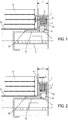
- a cheek (1) of a rolling shutter support is connected to a winding shaft (6) of a shutter apron (8) via a drive system essentially comprising a motor (2, 3). positioned in the cheek (1), provided hollow for this purpose and limited width b.
- the engine used in the examples of Figures 1 and 2 is a brushless motor whose stator (2), of annular section, is fixed on the inner face of the side wall (la) of the hollow cheek (1).
- the rotor (3) is rotatably mounted on a cylindrical bearing (1b) which extends inside the axis (6), a bearing (9) being interposed between the bearing (1b) and the rotor ( 3).
- the axis (6) is directly fixed on a flange (3a) of the rotor (3).
- the configuration of the figure 1 comprises a brushless motor called "outrunner” in which the rotor (3) is external to the stator (2), and also has an annular shape configuration whose inner face facing the stator (2) is provided with permanent magnets (4).
- the gap e existing between the rotor (3) and the stator (2) develops in an axial direction, parallel to the axis of rotation of the rotor (3), and is therefore tubular.
- the magnetic field created by the coils of the stator (2) is radial in shape, that is to say perpendicular to the axis of rotation of the rotor (3), as is the direction of polarization of the permanent magnets (4). ) of the rotor (2).
- An electronic card (7) for driving the brushless motor is for example secured to the cylindrical bearing (1a), and therefore placed in the winding axis (6) of the flap.
- the management of available space is substantially the same in the configuration of the figure 2 , but with a brushless motor with disk rotor (2), that is to say with rotor (2) in the form of a flat ring developing in a substantially transverse plane.
- the stator (2) has windings creating a magnetic field of axial direction, parallel to the axis of rotation of the rotor (3).
- the rotor (3) with central opening disc has, on its transverse face facing the stator (2), a plurality of permanent magnets (4) arranged vis-à-vis the stator windings (2).
- the air gap e thus created takes the form of a thin annular disk extending in a plane perpendicular to the axis of rotation (3a).
- the control of the motor by supplying the stator windings (2) with three-phase current, is carried out according to the detection the position of the rotor (3) at each moment.
- At least one position detection sensor in this case at least one Hall effect sensor (5), is therefore secured to the cheek (1) or the stator (2).
- a sensor (5) is shown fixed on the inner face of the side wall (1a) of the cheek (1), facing the permanent magnets (4) of the rotor (3).
- a sensor (5) is shown in the extension of the stator (2), oriented in an axial direction so as to face the permanent magnets (4) of the rotor (3).
- the engine control means are therefore provided for controlling the supply of the stator coils (2) in response to signals indicative of the position of the rotor (3). It is essentially a control electronics placed on a card (7) equipped with the electronic circuits necessary for the processing of the position signals coming from the sensor (s) (5) and then controlling the three-phase supply of three groups of coils of sequentially to create a magnetic field rotating at the same frequency as the power signals.
- Each permanent magnet (4) of the rotor (3) seeks to orient itself at each instant in the direction of the field created by the coils, the rotation of the rotor (3) resulting from the supply of said coils which is such that the generated field is always ahead of the position of the rotor (3).
- the electronic card (7) is positioned inside a hollow cylindrical central portion (1b) of the cheek (1) used as a bearing for the bearing (9). .
- This part (1b) is housed inside the axis (6) of winding of the motorized roller shutter.
Description
- La présente invention se situe dans le domaine des systèmes de fermeture motorisés de type volets roulants ou similaires. Elle a plus précisément trait aux supports motorisés de volets qui comportent un axe ou tube central autour duquel s'enroule le volet et, aux deux extrémités de l'axe, deux joues latérales qui peuvent faire partie de son coffre de rangement.
- De manière connue, un volet roulant comprend un tablier, généralement guidé verticalement par l'intermédiaire de glissières latérales et dont le bord supérieur est fixé à l'axe d'enroulement. Cet axe est relié à l'encadrement de l'ouverture à équiper du volet notamment au moyen desdites joues, qui bordent en fait latéralement la structure d'entraînement du tablier. L'axe est maintenu libre en rotation par rapport auxdites joues, et entraîné par un système manuel ou par un moteur d'entraînement.
- Lorsque le volet est motorisé, ce qui est le cas dans le cadre de l'invention, le dispositif d'entraînement est classiquement intégré dans l'axe d'enroulement et comporte un moteur électrique tubulaire couplé à au moins un réducteur également tubulaire placé dans le prolongement du moteur, la rotation du rotor étant transmise à l'axe d'enroulement via le réducteur. Historiquement, les moteurs utilisés étaient des moteurs asynchrones monophasés, choisis pour leur robustesse et leur coût raisonnable, mais qui présentent des inconvénients en termes de performances brutes et au démarrage.
- C'est la raison pour laquelle les moteurs synchrones sans balais, qui présentent un meilleur rendement et permettent une précision accrue dans la maîtrise des vitesses et couples d'entraînement, sont actuellement privilégiés pour ce type d'application, et remplacent progressivement les machines asynchrones. La technologie de ces moteurs et de leur module électronique de pilotage offre plus de possibilités de variation des paramètres de fonctionnement, avec une plage de variation des vitesses plus étendue et un maintien du couple. Le bruit et les vibrations générés par un moteur sans balai sont par ailleurs inférieurs à ce qui existe dans les autres types de moteur disponibles.
- Le moteur d'entraînement est associé à des moyens de pilotage électroniques disposés à proximité, par exemple à l'intérieur de l'axe d'enroulement, comme c'est par exemple montré dans le document
FR 2 883 913 - Le positionnement du dispositif d'entraînement dans l'axe présente des inconvénients liés d'une part à son emplacement, et d'autre part à la configuration technique qu'il implique. L'implantation des éléments constitutifs du dispositif à l'intérieur du volume de l'axe d'enroulement les rend plus difficile d'accès, et peut par conséquent rendre les opérations de maintenance potentiellement délicates. Les moteurs tubulaires compatibles avec les dimensions internes des axes, qui présentent typiquement des diamètres de l'ordre de 40 mm, fonctionnent par ailleurs nécessairement avec des réducteurs mécaniques du fait des vitesses requises pour obtenir des couples de fonctionnement compatibles avec l'enroulement de volets roulants. Une défaillance du dispositif d'entraînement peut donc résulter des différents maillons du système, c'est-à-dire du moteur proprement dit ou du/des réducteur(s), l'existence de composants distincts susceptibles de tomber séparément en panne diminuant la fiabilité de l'ensemble.
- Pour toutes ces raisons, il a été proposé des motorisations placées dans les joues latérales, comme c'est par exemple décrit dans les documents
WO 2005/088062 etWO 2001/77479 - Dans les deux cas, cependant, les configurations mécaniques sont plutôt complexes, essentiellement parce que les moteurs utilisés sont orientées de telle sorte que leur axe de rotation est d'allure perpendiculaire à l'axe de rotation du volet ou du store qu'ils motorisent. Il faut donc prévoir, en sortie de l'arbre moteur, des étages mécaniques permettant le changement d'orientation de la rotation et, le cas échéant, des étages d'adaptation de la vitesse, typiquement réducteurs, pour la rendre compatible avec la vitesse d'enroulement/déroulement des écrans obturateurs que constituent les volets/stores.
- Ces mécanismes dans les joues latérales sont volumineux, parfois bien plus que la section d'un coffre contenant un tel écran obturateur dans son état complètement enroulé, ce qui n'est guère pratique, et souvent peu esthétique. La complexité mécanique entraîne par ailleurs un risque accru de défaut de fiabilité, notamment du fait de l'usure ou de l'encrassement des composants. L'aspect économique de cette complexité est évidemment défavorable, le coût des multiples étages et composants étant loin d'être négligeable.
- L'invention remédie à ces insuffisances, et propose une solution mécaniquement et électriquement fiable, notamment parce qu'elle est robuste et simple à mettre en oeuvre et à utiliser. Cette solution est autant sinon plus adaptée que ses devancières en termes d'accès au système de motorisation, permettant de rendre les opérations de maintenance très aisées. Elle s'avère également fonctionnellement très adaptée au domaine des volets roulants motorisés.
- Selon l'invention, le support du volet roulant, comportant classiquement un axe d'enroulement du tablier du volet relié à ses extrémités axiales à des joues latérales, et des moyens d'entraînement motorisés dudit axe d'enroulement, lesdits moyens d'entraînement étant positionnés dans une des joues latérales, est tel que lesdits moyens d'entraînement consistent en un moteur électrique dont le rotor est relié à l'axe et le stator est solidarisé à la joue.
- Cette configuration est également particulièrement avantageuse en ce qu'elle est facilement pilotable par des moyens électroniques appropriés.
- De préférence, le moteur électrique est un moteur sans balai, qui présente comme mentionné auparavant un rendement supérieur aux moteurs asynchrones ou DC à balais, et dont la gestion électronique est particulièrement souple. Un moteur sans balais est plus compact qu'un moteur asynchrone de même puissance, de sorte qu'il est possible de le loger dans une joue. La facilité de mise en oeuvre de la commande de variation des vitesses permises par ce type de moteur permet par ailleurs de le régler pour un fonctionnement optimal, fonction de la charge (couple stable qui dépend de la tension de commande) mais également du niveau de bruit. Ce dernier paramètre n'est pas anodin, l'application au volet roulant relevant de l'habitat, et induisant des exigences liées au confort des habitants.
- De préférence encore, le moteur sans balai est à rotor externe situé en périphérie radiale du stator, à entrefer d'allure parallèle à l'axe de rotation du moteur. Dans un tel moteur dit « outrunner », les aimants permanents sont polarisés dans une direction radiale.
- Pour implanter le moteur dans la joue, et tirer parti des dimensions transversales de cette dernière, on utilise de fait un moteur plat, à grand diamètre, fonctionnant avec un grand couple et une vitesse réduite. Les aimants présents sur le rotor sont de fait disposés selon un diamètre important, ce qui crée un couple intéressant pour entraîner l'axe d'enroulement. L'utilisation d'un tel moteur « couple » permet de s'affranchir de l'utilisation d'un réducteur, les vitesses de fonctionnement étant compatibles avec les vitesses d'enroulement/déroulement d'un volet roulant. Ces moteurs « outrunner » sont particulièrement adaptés à des applications qui nécessitent un fort couple, dans lesquelles on peut en outre tirer parti de leur capacité à être reliés à la charge sans nécessiter de dispositif de réduction.
- Les moteurs sans balais fonctionnent en pratique avec des capteurs détectant la position du rotor, en général des capteurs à effet Hall qui permettent de connaître à tout moment la position du rotor et d'adapter en conséquence l'alimentation des bobines du stator et le champ magnétique. Ce mode de fonctionnement permet une excellente régulation de la vitesse et de la position. Dans une telle configuration plane intégrée à une joue, selon une possibilité, au moins un capteur de mesure de la position angulaire du rotor est placé sur la face interne de la paroi transversale de la joue, en regard des aimants permanents du rotor.
- Selon une variante possible, le moteur sans balais peut aussi être à rotor disque à entrefer d'allure perpendiculaire à l'axe de rotation du rotor, la direction de polarisation des aimants étant alors axiale. Dans ce cas, pour la détection de la position du rotor, au moins un capteur de mesure de la position angulaire du rotor peut être placé, en regard des aimants permanents du rotor, sur la face interne de la paroi axiale de la joue ou sur le stator dans une direction d'allure parallèle à ladite face interne.
- Dans les deux variantes, la configuration particulière du moteur, à grand diamètre et faible épaisseur pour se conformer à la géométrie de la joue, permet de travailler à couple et vitesse adéquates pour l'application au volet roulant, sans nécessiter le recours à un réducteur mécanique. L'épaisseur réduite de ces moteurs permet de limiter la largeur de la joue et par conséquent la distance entre l'axe (et donc le tablier) et le bord de l'ouverture dans laquelle le volet est installé.
- Le flasque du rotor est de préférence fixé à l'axe d'enroulement du tablier du volet, selon une liaison directe sans pièce intermédiaire. La présente invention simplifie en fait considérablement la structure du système de motorisation du volet, et en facilite la maintenance en rendant l'accès aux composants du système immédiat. Il est à noter que du fait même de cette conception simplifiée, augmentant la fiabilité de l'ensemble, les opérations de maintenance devraient en outre être sensiblement plus limitées.
- De préférence, le moteur est choisi avec un coefficient Kv inférieur à 1, de préférence compris entre 0,5 et 1, et de préférence encore de l'ordre de 0,5. Le coefficient Kv caractérise la capacité du moteur à transformer la puissance qu'il reçoit en couple ou en vitesse, la puissance étant le produit du couple par la vitesse de rotation. Ainsi, le choix d'un coefficient Kv plutôt faible (moteurs à fort couples) consacre la possibilité de disposer d'un couple suffisant pour entraîner en mouvement l'axe et le tablier du volet. Le choix d'un Kv faible indique au surplus l'utilisation d'un courant relativement faible et permet par conséquent d'obtenir un rendement plus élevé. Un Kv plutôt faible ne permet enfin qu'une accélération limitée, ce qui donne une impression d'onctuosité dans les mouvements du moteur, et donc du tablier de volet qu'il entraîne.
- La présente invention, qui s'applique à titre premier à des supports de volets roulants, concerne également les volets roulants qui en sont munis.
- L'invention va à présent être décrite plus en détail, en référence aux figures annexées, pour lesquelles :
- la
figure 1 représente très schématiquement une coupe axiale partielle d'une première variante de support de volet roulant montrant des moyens d'entraînement sous forme d'un moteur sans balais à entrefer parallèle à son axe de rotation ; et - la
figure 2 montre, selon un schéma similaire, une coupe axiale partielle d'une seconde variante de support de volet roulant dont les moyens d'entraînement sont sous forme d'un moteur sans balais à rotor disque à entrefer perpendiculaire à son axe de rotation. - En référence à la
figure 1 , une joue (1) d'un support de volet roulant est reliée à un axe (6) d'enroulement d'un tablier (8) de volet via un système d'entraînement comportant à titre essentiel un moteur (2, 3) positionné dans la joue (1), prévue creuse à cet effet et de largeur b limitée. Le moteur utilisé dans les exemples desfigures 1 et 2 est un moteur sans balais dont le stator (2), de section annulaire, est fixé sur la face interne de la paroi latérale (la) de la joue creuse (1). Le rotor (3) est monté libre en rotation sur un palier (1b) cylindrique qui s'étend à l'intérieur de l'axe (6), un roulement (9) étant interposé entre le palier (1b) et le rotor (3). Dans les exemples représentés, l'axe (6) est directement fixé sur un flasque (3a) du rotor (3). - La configuration de la
figure 1 comporte un moteur sans balais dit « outrunner » dans lequel le rotor (3) est externe au stator (2), et présente également une configuration d'allure annulaire dont la face intérieure en regard du stator (2) est munie d'aimants permanents (4). L'entrefer e existant entre le rotor (3) et le stator (2) se développe dans une direction axiale, parallèlement à l'axe de rotation du rotor (3), et est par conséquent de forme tubulaire. Le champ magnétique crée par les bobines du stator (2) est d'allure radiale, c'est-à-dire perpendiculaire à l'axe de rotation du rotor (3), de même que la direction de polarisation des aimants permanents (4) du rotor (2). - Une carte électronique (7) de pilotage du moteur sans balais est par exemple solidarisée au palier cylindrique (la), et par conséquent placée dans l'axe d'enroulement (6) du volet. Cette configuration à moteur plat localisé dans la joue (1) avec une carte électronique de pilotage (7) du moteur disposé centralement permet d'optimiser la gestion de l'espace utilisé par les moyens d'entraînement sans obérer les capacités d'entraînement du système, puisque le moteur à grand diamètre qui résulte de cette configuration est, en termes de couple généré et de vitesse de fonctionnement, particulièrement performant pour cette application aux volets roulants motorisés.
- La gestion de l'espace disponible est sensiblement la même dans la configuration de la
figure 2 , mais avec un moteur sans balais à rotor disque (2), c'est-à-dire à rotor (2) en forme d'anneau plat se développant dans un plan sensiblement transversal. Dans cette hypothèse, le stator (2) présente des bobinages créant un champ magnétique de direction axiale, parallèle à l'axe de rotation du rotor (3). Le rotor (3) à disque à ouverture centrale comporte, sur sa face transversale en regard du stator (2), une pluralité d'aimants permanents (4) disposés en vis-à-vis des bobinages du stator (2). L'entrefer e ainsi créé prend la forme d'un disque annulaire de faible épaisseur s'étendant dans un plan perpendiculaire à l'axe de rotation (3a). - Le pilotage du moteur, par alimentation des bobinages du stator (2) en courant triphasé, est réalisé suivant la détection de la position du rotor (3) à chaque instant. Au moins un capteur de détection de la position, en l'espèce au moins un capteur à effet Hall (5), est par conséquent solidarisé à la joue (1) ou au stator (2). Dans la configuration de la
figure 1 , un capteur (5) est représenté fixé sur la face interne de la paroi latérale (1a) de la joue (1), en regard des aimants permanents (4) du rotor (3) . - Dans la configuration à moteur sans balais à rotor (3) disque apparaissant en
figure 2 , un capteur (5) est figuré dans le prolongement du stator (2), orienté dans une direction axiale de manière à se placer en regard des aimants permanents (4) du rotor (3). Les moyens de commande du moteur sont donc prévus pour commander l'alimentation des bobines du stator (2) en réponse à des signaux indicatifs de la position du rotor(3). Il s'agit essentiellement d'une électronique de commande placée sur une carte (7) dotée des circuits électroniques nécessaires au traitement des signaux de position issus du ou des capteurs (5) et commandant ensuite l'alimentation triphasée de trois groupes de bobines de façon séquentielle pour créer un champ magnétique tournant à la même fréquence que les signaux d'alimentation. Chaque aimant permanent (4) du rotor (3) cherche à s'orienter à chaque instant dans le sens du champ créé par les bobinages, la rotation du rotor (3) résultant de l'alimentation desdits bobinages qui est telle que le champ généré est en permanence en avance sur la position du rotor (3). - Dans les deux configurations représentées, données à titre d'exemples, la carte électronique (7) est positionnée à l'intérieure d'une partie centrale cylindrique (1b) creuse de la joue (1) utilisée comme palier pour le roulement (9). Cette partie (1b) est logée à l'intérieur de l'axe (6) d'enroulement du volet roulant motorisé.
- L'invention ne se limite bien entendu pas aux exemples décrits et expliqués en référence aux figures, mais elle englobe les variantes et versions qui entrent dans la portée des revendications.
Claims (10)
- Support de volet roulant, comportant un axe d'enroulement (6) du tablier (8) du volet relié à ses extrémités axiales à des joues latérales (1) et des moyens d'entraînement (2, 3) motorisés dudit axe d'enroulement (6), lesdits moyens d'entraînement (2, 3) étant positionnés dans une des joues latérales (1), caractérisé en ce que les moyens d'entraînement consistent en un moteur électrique dont le rotor (3) est relié à l'axe (6) et le stator (2) est solidarisé à la joue (1).
- Support de volet roulant selon la revendication précédente, caractérisé en ce que le moteur électrique est un moteur sans balai.
- Support de volet roulant selon la revendication précédente, caractérisé en ce que le moteur sans balai est à rotor (3) externe situé en périphérie radiale du stator (2), à entrefer e d'allure parallèle à l'axe de rotation du moteur.
- Support de volet roulant selon la revendication précédente, caractérisé en ce qu'au moins un capteur (5) de mesure de la position angulaire du rotor (3) est placé sur la face interne de la paroi transversale (la) de la joue (1) en regard des aimants permanents (4) du rotor (3).
- Support de volet roulant selon la revendication 2, caractérisé en ce que le moteur sans balai est à rotor (3) disque à entrefer e d'allure perpendiculaire à l'axe de rotation du rotor.
- Support de volet roulant selon la revendication précédente, caractérisé en ce qu'au moins un capteur (5) de mesure de la position angulaire du rotor (3) est placé, en regard des aimants permanents (4) du rotor (3), sur la face interne de la paroi axiale de la joue (1) ou sur le stator (2) parallèlement à ladite face interne.
- Support de volet roulant selon l'une des revendications précédentes, caractérisé en ce que le flasque du rotor (3) est fixé à l'axe d'enroulement (6) du tablier (8) du volet.
- Support de volet roulant selon l'une des revendications précédentes, caractérisé en ce que le coefficient Kv du moteur est inférieur à 1.
- Support de volet roulant selon la revendication précédente, caractérisé en ce que le coefficient Kv du moteur est compris entre 0,5 et 1, de préférence de l'ordre de 0,5.
- Volet roulant motorisé comportant un support selon les revendications précédentes.
Priority Applications (1)
| Application Number | Priority Date | Filing Date | Title |
|---|---|---|---|
| PL16195418T PL3165704T3 (pl) | 2015-11-03 | 2016-10-25 | Nośnik zasłony zwijanej ze ścianką boczną zawierającą środki napędowe |
Applications Claiming Priority (1)
| Application Number | Priority Date | Filing Date | Title |
|---|---|---|---|
| FR1560516A FR3043129B1 (fr) | 2015-11-03 | 2015-11-03 | Support de volet roulant a joue laterale incluant les moyens d'entrainement. |
Publications (2)
| Publication Number | Publication Date |
|---|---|
| EP3165704A1 EP3165704A1 (fr) | 2017-05-10 |
| EP3165704B1 true EP3165704B1 (fr) | 2018-08-15 |
Family
ID=55135347
Family Applications (1)
| Application Number | Title | Priority Date | Filing Date |
|---|---|---|---|
| EP16195418.5A Active EP3165704B1 (fr) | 2015-11-03 | 2016-10-25 | Support de volet roulant à joue latérale incluant les moyens d'entraînement |
Country Status (5)
| Country | Link |
|---|---|
| EP (1) | EP3165704B1 (fr) |
| ES (1) | ES2693390T3 (fr) |
| FR (1) | FR3043129B1 (fr) |
| PL (1) | PL3165704T3 (fr) |
| WO (1) | WO2020099273A1 (fr) |
Family Cites Families (8)
| Publication number | Priority date | Publication date | Assignee | Title |
|---|---|---|---|---|
| US6497267B1 (en) * | 2000-04-07 | 2002-12-24 | Lutron Electronics Co., Inc. | Motorized window shade with ultraquiet motor drive and ESD protection |
| US20040108744A1 (en) * | 2002-12-10 | 2004-06-10 | Scheib Chales J. | Structural hybrid attachment system |
| US20080163989A1 (en) * | 2004-03-11 | 2008-07-10 | Michael Pal Sales | Drive Unit For Raising And/Or Lowering A Roller Shutter |
| FR2883913A1 (fr) | 2005-04-05 | 2006-10-06 | Bubendorff Sa | Dispositif d'entrainement a moteur tubulaire, notamment pour systeme de fermeture motorise |
| DE102006040624A1 (de) * | 2005-09-07 | 2007-05-16 | Behr Gmbh & Co Kg | Querträgeranordnung, insbesondere für ein Kraftfahrzeug |
| AU2011229138A1 (en) * | 2010-03-16 | 2012-10-11 | Automatic Technology (Australia) Pty Ltd | Operator mechanism |
| US10940609B2 (en) * | 2017-07-25 | 2021-03-09 | Divergent Technologies, Inc. | Methods and apparatus for additively manufactured endoskeleton-based transport structures |
| EP3508399B1 (fr) * | 2018-01-09 | 2023-02-22 | Motherson Innovations Company Limited | Structure de support autoportant pour un tableau de bord dans un véhicule, tableau de bord comprenant une telle structure de support et véhicule équipé d'un tel tableau de bord |
-
2015
- 2015-11-03 FR FR1560516A patent/FR3043129B1/fr not_active Expired - Fee Related
-
2016
- 2016-10-25 EP EP16195418.5A patent/EP3165704B1/fr active Active
- 2016-10-25 ES ES16195418.5T patent/ES2693390T3/es active Active
- 2016-10-25 PL PL16195418T patent/PL3165704T3/pl unknown
-
2019
- 2019-11-08 WO PCT/EP2019/080729 patent/WO2020099273A1/fr unknown
Non-Patent Citations (1)
| Title |
|---|
| None * |
Also Published As
| Publication number | Publication date |
|---|---|
| ES2693390T3 (es) | 2018-12-11 |
| FR3043129A1 (fr) | 2017-05-05 |
| PL3165704T3 (pl) | 2019-03-29 |
| WO2020099273A1 (fr) | 2020-05-22 |
| EP3165704A1 (fr) | 2017-05-10 |
| FR3043129B1 (fr) | 2018-09-07 |
Similar Documents
| Publication | Publication Date | Title |
|---|---|---|
| EP1481459B1 (fr) | Actionneur lineaire comprenant un moteur electrique polyphase sans balais | |
| EP2588369B1 (fr) | Alimentation electrique des equipements portes par un support rotatif | |
| EP1323223A1 (fr) | Moto-reducteur commute sur un signal de position absolu | |
| EP2582576B1 (fr) | Alimentation electrique des equipements portes par le rotor d'un moteur d'aeronef | |
| FR3056360B1 (fr) | Moto-reducteur, systeme d'essuyage et procede de commande associes | |
| WO2018091302A1 (fr) | Moto-reducteur, systeme d'essuyage et procede de commande associes | |
| EP3516756A1 (fr) | Moteur electrique a courant continu sans balais pour systeme d'essuyage de vehicule automobile | |
| EP1479443A1 (fr) | Système d'entraínement d'une centrifugeuse | |
| EP3165704B1 (fr) | Support de volet roulant à joue latérale incluant les moyens d'entraînement | |
| WO2018054574A1 (fr) | Moteur electrique a courant continu sans balais pour systeme d'essuyage de vehicule automobile | |
| WO2014013147A1 (fr) | Actionneur comprenant deux moteur paliers magnétiques | |
| FR2966301A1 (fr) | Procede de gestion d'actionneurs electromecaniques a double bobinage. | |
| EP3652840A1 (fr) | Procede de pilotage d'une machine electrique tournante polyphasee et machine electrique tournante mettant en oeuvre ce procede | |
| FR2938713A1 (fr) | Moteur electrique a montage coaxial | |
| WO2021028760A1 (fr) | Système de vis-écrou magnétiques | |
| WO2017182748A1 (fr) | Systeme d'actionnement simplifie de pas pour une helice de turbomachine | |
| FR3060523A1 (fr) | Systeme d'actionnement electromecanique de pas pour une helice de turbomachine | |
| WO2014161911A1 (fr) | Moteur electrique a faible couple de court-circuit, dispositif de motorisation a plusieurs moteurs et procede de fabrication d'un tel moteur | |
| EP3396817B1 (fr) | Motoréducteur à freinage magnétique | |
| FR3060526A1 (fr) | Systeme d'actionnement electromecanique de pas pour une helice de turbomachine | |
| FR3037734B1 (fr) | Rotor a toles empilees. | |
| EP0549429A1 (fr) | Rotor à aimants permanents doté d'une indication de sa position angulaire instantanée et machine magnéto-dynamique, comme un moteur sans collecteur, équipée d'un tel rotor | |
| FR2570229A1 (fr) | Moteur a courant continu, sans collecteur, pour grandes vitesses de rotation | |
| EP3109983B1 (fr) | Machine électrique tournante synchrone compacte | |
| EP4154391A1 (fr) | Dispositif d'enroulement/déroulement d'un lien |
Legal Events
| Date | Code | Title | Description |
|---|---|---|---|
| PUAI | Public reference made under article 153(3) epc to a published international application that has entered the european phase |
Free format text: ORIGINAL CODE: 0009012 |
|
| AK | Designated contracting states |
Kind code of ref document: A1 Designated state(s): AL AT BE BG CH CY CZ DE DK EE ES FI FR GB GR HR HU IE IS IT LI LT LU LV MC MK MT NL NO PL PT RO RS SE SI SK SM TR |
|
| AX | Request for extension of the european patent |
Extension state: BA ME |
|
| 17P | Request for examination filed |
Effective date: 20171019 |
|
| RBV | Designated contracting states (corrected) |
Designated state(s): AL AT BE BG CH CY CZ DE DK EE ES FI FR GB GR HR HU IE IS IT LI LT LU LV MC MK MT NL NO PL PT RO RS SE SI SK SM TR |
|
| GRAP | Despatch of communication of intention to grant a patent |
Free format text: ORIGINAL CODE: EPIDOSNIGR1 |
|
| RIC1 | Information provided on ipc code assigned before grant |
Ipc: E06B 9/72 20060101ALI20180215BHEP Ipc: E06B 9/17 20060101AFI20180215BHEP Ipc: E06B 9/70 20060101ALI20180215BHEP |
|
| INTG | Intention to grant announced |
Effective date: 20180308 |
|
| GRAS | Grant fee paid |
Free format text: ORIGINAL CODE: EPIDOSNIGR3 |
|
| GRAA | (expected) grant |
Free format text: ORIGINAL CODE: 0009210 |
|
| AK | Designated contracting states |
Kind code of ref document: B1 Designated state(s): AL AT BE BG CH CY CZ DE DK EE ES FI FR GB GR HR HU IE IS IT LI LT LU LV MC MK MT NL NO PL PT RO RS SE SI SK SM TR |
|
| REG | Reference to a national code |
Ref country code: CH Ref legal event code: EP Ref country code: GB Ref legal event code: FG4D Free format text: NOT ENGLISH Ref country code: AT Ref legal event code: REF Ref document number: 1029970 Country of ref document: AT Kind code of ref document: T Effective date: 20180815 |
|
| REG | Reference to a national code |
Ref country code: IE Ref legal event code: FG4D Free format text: LANGUAGE OF EP DOCUMENT: FRENCH |
|
| REG | Reference to a national code |
Ref country code: DE Ref legal event code: R096 Ref document number: 602016004772 Country of ref document: DE |
|
| REG | Reference to a national code |
Ref country code: FR Ref legal event code: PLFP Year of fee payment: 3 |
|
| REG | Reference to a national code |
Ref country code: ES Ref legal event code: FG2A Ref document number: 2693390 Country of ref document: ES Kind code of ref document: T3 Effective date: 20181211 |
|
| REG | Reference to a national code |
Ref country code: NL Ref legal event code: MP Effective date: 20180815 |
|
| REG | Reference to a national code |
Ref country code: LT Ref legal event code: MG4D |
|
| REG | Reference to a national code |
Ref country code: AT Ref legal event code: MK05 Ref document number: 1029970 Country of ref document: AT Kind code of ref document: T Effective date: 20180815 |
|
| PG25 | Lapsed in a contracting state [announced via postgrant information from national office to epo] |
Ref country code: GR Free format text: LAPSE BECAUSE OF FAILURE TO SUBMIT A TRANSLATION OF THE DESCRIPTION OR TO PAY THE FEE WITHIN THE PRESCRIBED TIME-LIMIT Effective date: 20181116 Ref country code: NO Free format text: LAPSE BECAUSE OF FAILURE TO SUBMIT A TRANSLATION OF THE DESCRIPTION OR TO PAY THE FEE WITHIN THE PRESCRIBED TIME-LIMIT Effective date: 20181115 Ref country code: SE Free format text: LAPSE BECAUSE OF FAILURE TO SUBMIT A TRANSLATION OF THE DESCRIPTION OR TO PAY THE FEE WITHIN THE PRESCRIBED TIME-LIMIT Effective date: 20180815 Ref country code: FI Free format text: LAPSE BECAUSE OF FAILURE TO SUBMIT A TRANSLATION OF THE DESCRIPTION OR TO PAY THE FEE WITHIN THE PRESCRIBED TIME-LIMIT Effective date: 20180815 Ref country code: RS Free format text: LAPSE BECAUSE OF FAILURE TO SUBMIT A TRANSLATION OF THE DESCRIPTION OR TO PAY THE FEE WITHIN THE PRESCRIBED TIME-LIMIT Effective date: 20180815 Ref country code: LT Free format text: LAPSE BECAUSE OF FAILURE TO SUBMIT A TRANSLATION OF THE DESCRIPTION OR TO PAY THE FEE WITHIN THE PRESCRIBED TIME-LIMIT Effective date: 20180815 Ref country code: IS Free format text: LAPSE BECAUSE OF FAILURE TO SUBMIT A TRANSLATION OF THE DESCRIPTION OR TO PAY THE FEE WITHIN THE PRESCRIBED TIME-LIMIT Effective date: 20181215 Ref country code: AT Free format text: LAPSE BECAUSE OF FAILURE TO SUBMIT A TRANSLATION OF THE DESCRIPTION OR TO PAY THE FEE WITHIN THE PRESCRIBED TIME-LIMIT Effective date: 20180815 Ref country code: NL Free format text: LAPSE BECAUSE OF FAILURE TO SUBMIT A TRANSLATION OF THE DESCRIPTION OR TO PAY THE FEE WITHIN THE PRESCRIBED TIME-LIMIT Effective date: 20180815 Ref country code: BG Free format text: LAPSE BECAUSE OF FAILURE TO SUBMIT A TRANSLATION OF THE DESCRIPTION OR TO PAY THE FEE WITHIN THE PRESCRIBED TIME-LIMIT Effective date: 20181115 |
|
| PG25 | Lapsed in a contracting state [announced via postgrant information from national office to epo] |
Ref country code: AL Free format text: LAPSE BECAUSE OF FAILURE TO SUBMIT A TRANSLATION OF THE DESCRIPTION OR TO PAY THE FEE WITHIN THE PRESCRIBED TIME-LIMIT Effective date: 20180815 Ref country code: LV Free format text: LAPSE BECAUSE OF FAILURE TO SUBMIT A TRANSLATION OF THE DESCRIPTION OR TO PAY THE FEE WITHIN THE PRESCRIBED TIME-LIMIT Effective date: 20180815 Ref country code: HR Free format text: LAPSE BECAUSE OF FAILURE TO SUBMIT A TRANSLATION OF THE DESCRIPTION OR TO PAY THE FEE WITHIN THE PRESCRIBED TIME-LIMIT Effective date: 20180815 |
|
| PG25 | Lapsed in a contracting state [announced via postgrant information from national office to epo] |
Ref country code: CZ Free format text: LAPSE BECAUSE OF FAILURE TO SUBMIT A TRANSLATION OF THE DESCRIPTION OR TO PAY THE FEE WITHIN THE PRESCRIBED TIME-LIMIT Effective date: 20180815 Ref country code: RO Free format text: LAPSE BECAUSE OF FAILURE TO SUBMIT A TRANSLATION OF THE DESCRIPTION OR TO PAY THE FEE WITHIN THE PRESCRIBED TIME-LIMIT Effective date: 20180815 Ref country code: EE Free format text: LAPSE BECAUSE OF FAILURE TO SUBMIT A TRANSLATION OF THE DESCRIPTION OR TO PAY THE FEE WITHIN THE PRESCRIBED TIME-LIMIT Effective date: 20180815 |
|
| REG | Reference to a national code |
Ref country code: DE Ref legal event code: R097 Ref document number: 602016004772 Country of ref document: DE |
|
| PG25 | Lapsed in a contracting state [announced via postgrant information from national office to epo] |
Ref country code: SM Free format text: LAPSE BECAUSE OF FAILURE TO SUBMIT A TRANSLATION OF THE DESCRIPTION OR TO PAY THE FEE WITHIN THE PRESCRIBED TIME-LIMIT Effective date: 20180815 Ref country code: SK Free format text: LAPSE BECAUSE OF FAILURE TO SUBMIT A TRANSLATION OF THE DESCRIPTION OR TO PAY THE FEE WITHIN THE PRESCRIBED TIME-LIMIT Effective date: 20180815 Ref country code: DK Free format text: LAPSE BECAUSE OF FAILURE TO SUBMIT A TRANSLATION OF THE DESCRIPTION OR TO PAY THE FEE WITHIN THE PRESCRIBED TIME-LIMIT Effective date: 20180815 |
|
| PLBE | No opposition filed within time limit |
Free format text: ORIGINAL CODE: 0009261 |
|
| STAA | Information on the status of an ep patent application or granted ep patent |
Free format text: STATUS: NO OPPOSITION FILED WITHIN TIME LIMIT |
|
| REG | Reference to a national code |
Ref country code: BE Ref legal event code: MM Effective date: 20181031 |
|
| PG25 | Lapsed in a contracting state [announced via postgrant information from national office to epo] |
Ref country code: MC Free format text: LAPSE BECAUSE OF FAILURE TO SUBMIT A TRANSLATION OF THE DESCRIPTION OR TO PAY THE FEE WITHIN THE PRESCRIBED TIME-LIMIT Effective date: 20180815 Ref country code: LU Free format text: LAPSE BECAUSE OF NON-PAYMENT OF DUE FEES Effective date: 20181025 |
|
| 26N | No opposition filed |
Effective date: 20190516 |
|
| REG | Reference to a national code |
Ref country code: IE Ref legal event code: MM4A |
|
| PG25 | Lapsed in a contracting state [announced via postgrant information from national office to epo] |
Ref country code: SI Free format text: LAPSE BECAUSE OF FAILURE TO SUBMIT A TRANSLATION OF THE DESCRIPTION OR TO PAY THE FEE WITHIN THE PRESCRIBED TIME-LIMIT Effective date: 20180815 Ref country code: BE Free format text: LAPSE BECAUSE OF NON-PAYMENT OF DUE FEES Effective date: 20181031 |
|
| PG25 | Lapsed in a contracting state [announced via postgrant information from national office to epo] |
Ref country code: IE Free format text: LAPSE BECAUSE OF NON-PAYMENT OF DUE FEES Effective date: 20181025 |
|
| PG25 | Lapsed in a contracting state [announced via postgrant information from national office to epo] |
Ref country code: MT Free format text: LAPSE BECAUSE OF FAILURE TO SUBMIT A TRANSLATION OF THE DESCRIPTION OR TO PAY THE FEE WITHIN THE PRESCRIBED TIME-LIMIT Effective date: 20180815 |
|
| PG25 | Lapsed in a contracting state [announced via postgrant information from national office to epo] |
Ref country code: TR Free format text: LAPSE BECAUSE OF FAILURE TO SUBMIT A TRANSLATION OF THE DESCRIPTION OR TO PAY THE FEE WITHIN THE PRESCRIBED TIME-LIMIT Effective date: 20180815 |
|
| PG25 | Lapsed in a contracting state [announced via postgrant information from national office to epo] |
Ref country code: PT Free format text: LAPSE BECAUSE OF FAILURE TO SUBMIT A TRANSLATION OF THE DESCRIPTION OR TO PAY THE FEE WITHIN THE PRESCRIBED TIME-LIMIT Effective date: 20180815 |
|
| REG | Reference to a national code |
Ref country code: CH Ref legal event code: PL |
|
| PG25 | Lapsed in a contracting state [announced via postgrant information from national office to epo] |
Ref country code: CY Free format text: LAPSE BECAUSE OF FAILURE TO SUBMIT A TRANSLATION OF THE DESCRIPTION OR TO PAY THE FEE WITHIN THE PRESCRIBED TIME-LIMIT Effective date: 20180815 Ref country code: HU Free format text: LAPSE BECAUSE OF FAILURE TO SUBMIT A TRANSLATION OF THE DESCRIPTION OR TO PAY THE FEE WITHIN THE PRESCRIBED TIME-LIMIT; INVALID AB INITIO Effective date: 20161025 Ref country code: MK Free format text: LAPSE BECAUSE OF NON-PAYMENT OF DUE FEES Effective date: 20180815 |
|
| PG25 | Lapsed in a contracting state [announced via postgrant information from national office to epo] |
Ref country code: CH Free format text: LAPSE BECAUSE OF NON-PAYMENT OF DUE FEES Effective date: 20191031 Ref country code: LI Free format text: LAPSE BECAUSE OF NON-PAYMENT OF DUE FEES Effective date: 20191031 |
|
| GBPC | Gb: european patent ceased through non-payment of renewal fee |
Effective date: 20201025 |
|
| PG25 | Lapsed in a contracting state [announced via postgrant information from national office to epo] |
Ref country code: GB Free format text: LAPSE BECAUSE OF NON-PAYMENT OF DUE FEES Effective date: 20201025 |
|
| PGFP | Annual fee paid to national office [announced via postgrant information from national office to epo] |
Ref country code: PL Payment date: 20230927 Year of fee payment: 8 |
|
| PGFP | Annual fee paid to national office [announced via postgrant information from national office to epo] |
Ref country code: ES Payment date: 20231204 Year of fee payment: 8 |
|
| PGFP | Annual fee paid to national office [announced via postgrant information from national office to epo] |
Ref country code: IT Payment date: 20231027 Year of fee payment: 8 Ref country code: FR Payment date: 20231018 Year of fee payment: 8 Ref country code: DE Payment date: 20231027 Year of fee payment: 8 |