EP3165704B1 - Halterung eines rollladens mit seitlicher wange die antriebsmittel beinhaltet - Google Patents
Halterung eines rollladens mit seitlicher wange die antriebsmittel beinhaltet Download PDFInfo
- Publication number
- EP3165704B1 EP3165704B1 EP16195418.5A EP16195418A EP3165704B1 EP 3165704 B1 EP3165704 B1 EP 3165704B1 EP 16195418 A EP16195418 A EP 16195418A EP 3165704 B1 EP3165704 B1 EP 3165704B1
- Authority
- EP
- European Patent Office
- Prior art keywords
- rotor
- roller shutter
- motor
- shutter mounting
- mounting according
- Prior art date
- Legal status (The legal status is an assumption and is not a legal conclusion. Google has not performed a legal analysis and makes no representation as to the accuracy of the status listed.)
- Active
Links
Images
Classifications
-
- B—PERFORMING OPERATIONS; TRANSPORTING
- B62—LAND VEHICLES FOR TRAVELLING OTHERWISE THAN ON RAILS
- B62D—MOTOR VEHICLES; TRAILERS
- B62D25/00—Superstructure or monocoque structure sub-units; Parts or details thereof not otherwise provided for
- B62D25/08—Front or rear portions
- B62D25/14—Dashboards as superstructure sub-units
- B62D25/145—Dashboards as superstructure sub-units having a crossbeam incorporated therein
-
- B—PERFORMING OPERATIONS; TRANSPORTING
- B62—LAND VEHICLES FOR TRAVELLING OTHERWISE THAN ON RAILS
- B62D—MOTOR VEHICLES; TRAILERS
- B62D29/00—Superstructures, understructures, or sub-units thereof, characterised by the material thereof
- B62D29/04—Superstructures, understructures, or sub-units thereof, characterised by the material thereof predominantly of synthetic material
Definitions
- the present invention is in the field of motorized shutter type closing systems or the like. More specifically, it relates to motorized shutter supports which comprise a central axis or tube around which the shutter is wound and, at both ends of the axis, two lateral cheeks which can be part of its storage compartment.
- a roller shutter comprises an apron, generally guided vertically by means of side rails and whose upper edge is fixed to the winding axis.
- This axis is connected to the frame of the opening to be equipped with the flap in particular by means of said cheeks, which border in fact sideways the drive structure of the deck.
- the axis is kept free in rotation relative to said cheeks, and driven by a manual system or by a drive motor.
- the drive device is conventionally integrated in the winding axis and comprises a tubular electric motor coupled to at least one also tubular reducer placed in the extension of the motor, the rotation of the rotor being transmitted to the winding axis via the gearbox.
- the motors used were single-phase asynchronous motors, chosen for their robustness and reasonable cost, but which have disadvantages in terms of raw performance and startup.
- the drive motor is associated with electronic control means arranged in proximity, for example within the winding axis, as is shown for example in the document FR 2,883,913 .
- the electronic control or control means may be positioned at the end of the axis, for example fixed on the internal face of a lateral cheek.
- the positioning of the drive device in the axis has drawbacks related on the one hand to its location, and on the other hand to the technical configuration it implies.
- the implementation of the constituent elements of the device within the volume of the winding axis makes them more difficult to access, and can therefore make maintenance operations potentially difficult.
- Tubular motors compatible with the internal dimensions of the axes which typically have diameters of the order of 40 mm, necessarily also operate with mechanical reducers because of the speeds required to obtain operating torques compatible with the winding of shutters. rolling.
- a failure of the drive device may therefore result from the different links of the system, that is to say from the actual engine or from the gearbox (s), the existence of separate components capable of falling apart separately decreasing the reliability of the whole.
- the invention overcomes these shortcomings, and proposes a mechanically and electrically reliable solution, in particular because it is robust and simple to implement and use.
- This solution is as much if not more suitable than its predecessors in terms of access to the engine system, making maintenance operations very easy. It is also functionally very adapted to the field of motorized roller shutters.
- the support of the shutter conventionally comprising a winding axis of the shutter of the shutter connected at its axial ends to side cheeks, and motorized drive means of said winding axis, said drive means being positioned in one of the lateral cheeks, is such that said drive means consist of an electric motor whose rotor is connected to the axis and the stator is secured to the cheek.
- This configuration is also particularly advantageous in that it is easily controllable by appropriate electronic means.
- the electric motor is a brushless motor, which has, as previously mentioned, a higher efficiency than asynchronous or DC brushed motors, and whose management electronic is particularly flexible.
- a brushless motor is more compact than an asynchronous motor of the same power, so that it can be housed in a cheek.
- the ease of implementation of the speed variation control allowed by this type of motor also allows it to be set for optimum operation, depending on the load (stable torque which depends on the control voltage) but also on the level of noise. This last parameter is not insignificant, the application to the rolling shutter pertaining to the habitat, and inducing requirements related to the comfort of the inhabitants.
- the brushless motor is an external rotor located at the radial periphery of the stator, with air gap parallel to the axis of rotation of the motor.
- the permanent magnets are polarized in a radial direction.
- Brushless motors operate in practice with sensors detecting the position of the rotor, generally Hall effect sensors that allow to know at any time the position of the rotor and to adapt accordingly the power supply of the stator coils and the field magnetic. This mode of operation allows excellent speed and position control.
- sensors detecting the position of the rotor generally Hall effect sensors that allow to know at any time the position of the rotor and to adapt accordingly the power supply of the stator coils and the field magnetic. This mode of operation allows excellent speed and position control.
- at least one sensor for measuring the angular position of the rotor is placed on the inner face of the transverse wall of the cheek, facing the permanent magnets of the rotor.
- the brushless motor may also be a disk rotor with air gap of a shape perpendicular to the axis of rotation of the rotor, the direction of polarization of the magnets then being axial.
- at least one sensor for measuring the angular position of the rotor can be placed, opposite the permanent magnets of the rotor, on the internal face of the axial wall of the cheek or on the stator in a direction parallel to said internal face.
- the particular configuration of the engine large diameter and small thickness to comply with the geometry of the cheek, allows to work at the appropriate torque and speed for the application to the shutter, without the need for a gearbox mechanical.
- the reduced thickness of these motors limits the width of the cheek and therefore the distance between the axis (and therefore the apron) and the edge of the opening in which the shutter is installed.
- the flange of the rotor is preferably attached to the winding axis of the shutter apron, in a direct connection without intermediate piece.
- the present invention in fact greatly simplifies the structure of the shutter drive system, and facilitates maintenance by making access to components of the immediate system. It should be noted that by the very fact of this simplified design, increasing the reliability of the assembly, maintenance operations should be significantly more limited.
- the motor is chosen with a Kv coefficient of less than 1, preferably between 0.5 and 1, and more preferably of the order of 0.5.
- the coefficient Kv characterizes the capacity of the motor to transform the power that it receives in torque or speed, the power being the product of the torque by the speed of rotation. So, choosing a Kv coefficient rather low (motors with strong torques) devotes the possibility of having enough torque to drive the axle and the apron of the shutter in movement.
- the choice of a low Kv indicates in addition the use of a relatively low current and therefore allows to obtain a higher yield.
- a rather weak Kv finally allows a limited acceleration, which gives an impression of creaminess in the movements of the engine, and therefore the shutter apron that leads.
- the present invention which applies firstly to roller shutter supports, also relates to shutters which are provided.
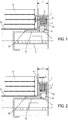
- a cheek (1) of a rolling shutter support is connected to a winding shaft (6) of a shutter apron (8) via a drive system essentially comprising a motor (2, 3). positioned in the cheek (1), provided hollow for this purpose and limited width b.
- the engine used in the examples of Figures 1 and 2 is a brushless motor whose stator (2), of annular section, is fixed on the inner face of the side wall (la) of the hollow cheek (1).
- the rotor (3) is rotatably mounted on a cylindrical bearing (1b) which extends inside the axis (6), a bearing (9) being interposed between the bearing (1b) and the rotor ( 3).
- the axis (6) is directly fixed on a flange (3a) of the rotor (3).
- the configuration of the figure 1 comprises a brushless motor called "outrunner” in which the rotor (3) is external to the stator (2), and also has an annular shape configuration whose inner face facing the stator (2) is provided with permanent magnets (4).
- the gap e existing between the rotor (3) and the stator (2) develops in an axial direction, parallel to the axis of rotation of the rotor (3), and is therefore tubular.
- the magnetic field created by the coils of the stator (2) is radial in shape, that is to say perpendicular to the axis of rotation of the rotor (3), as is the direction of polarization of the permanent magnets (4). ) of the rotor (2).
- An electronic card (7) for driving the brushless motor is for example secured to the cylindrical bearing (1a), and therefore placed in the winding axis (6) of the flap.
- the management of available space is substantially the same in the configuration of the figure 2 , but with a brushless motor with disk rotor (2), that is to say with rotor (2) in the form of a flat ring developing in a substantially transverse plane.
- the stator (2) has windings creating a magnetic field of axial direction, parallel to the axis of rotation of the rotor (3).
- the rotor (3) with central opening disc has, on its transverse face facing the stator (2), a plurality of permanent magnets (4) arranged vis-à-vis the stator windings (2).
- the air gap e thus created takes the form of a thin annular disk extending in a plane perpendicular to the axis of rotation (3a).
- the control of the motor by supplying the stator windings (2) with three-phase current, is carried out according to the detection the position of the rotor (3) at each moment.
- At least one position detection sensor in this case at least one Hall effect sensor (5), is therefore secured to the cheek (1) or the stator (2).
- a sensor (5) is shown fixed on the inner face of the side wall (1a) of the cheek (1), facing the permanent magnets (4) of the rotor (3).
- a sensor (5) is shown in the extension of the stator (2), oriented in an axial direction so as to face the permanent magnets (4) of the rotor (3).
- the engine control means are therefore provided for controlling the supply of the stator coils (2) in response to signals indicative of the position of the rotor (3). It is essentially a control electronics placed on a card (7) equipped with the electronic circuits necessary for the processing of the position signals coming from the sensor (s) (5) and then controlling the three-phase supply of three groups of coils of sequentially to create a magnetic field rotating at the same frequency as the power signals.
- Each permanent magnet (4) of the rotor (3) seeks to orient itself at each instant in the direction of the field created by the coils, the rotation of the rotor (3) resulting from the supply of said coils which is such that the generated field is always ahead of the position of the rotor (3).
- the electronic card (7) is positioned inside a hollow cylindrical central portion (1b) of the cheek (1) used as a bearing for the bearing (9). .
- This part (1b) is housed inside the axis (6) of winding of the motorized roller shutter.
Landscapes
- Engineering & Computer Science (AREA)
- Chemical & Material Sciences (AREA)
- Combustion & Propulsion (AREA)
- Transportation (AREA)
- Mechanical Engineering (AREA)
- Architecture (AREA)
- Structural Engineering (AREA)
- Operating, Guiding And Securing Of Roll- Type Closing Members (AREA)
- Body Structure For Vehicles (AREA)
Claims (10)
- Rollladenhalter, umfassend eine Achse (6) zum Aufwickeln des Panzers (8) des Rollladens, die an ihren axialen Enden mit seitlichen Seitenstücken (1) und motorisierten Antriebsmitteln (2, 3) der Wickelachse (6) verbunden ist, wobei die Antriebsmittel (2, 3) in einem der seitlichen Seitenstücke (1) positioniert sind, dadurch gekennzeichnet, dass die Antriebsmittel aus einem Elektromotor, dessen Rotor (3) mit der Achse (6) verbunden ist, bestehen und der Stator (2) mit dem Seitenstück (1) fest verbunden ist.
- Rollladenhalter nach dem vorhergehenden Anspruch, dadurch gekennzeichnet, dass der Elektromotor ein bürstenloser Motor ist.
- Rollladenhalter nach dem vorhergehenden Anspruch, dadurch gekennzeichnet, dass der bürstenlose Motor einen externen Rotor (3), der sich an der radialen Peripherie des Stators (2) befindet, und einen Luftspalt e, der zur Drehachse des Motors parallel gestaltet ist, aufweist.
- Rollladenhalter nach dem vorhergehenden Anspruch, dadurch gekennzeichnet, dass mindestens ein Sensor (5) zum Messen der Winkelposition des Rotors (3) auf der internen Seite der Querwand (la) des Seitenstücks (1) gegenüber den Dauermagneten (4) des Rotors (3) angeordnet ist.
- Rollladenhalter nach Anspruch 2, dadurch gekennzeichnet, dass der bürstenlose Motor einen Scheibenrotor (3) aufweist, der einen Luftspalt e aufweist, der zur Drehachse des Rotors rechtwinklig gestaltet ist.
- Rollladenhalter nach dem vorhergehenden Anspruch, dadurch gekennzeichnet, dass mindestens ein Sensor (5) zum Messen der Winkelposition des Rotors (3) den Dauermagneten (4) des Rotors (3) gegenüber auf der internen Seite der axialen Wand des Seitenstücks (1) oder an dem Stator (2) parallel zur internen Seite angeordnet ist.
- Rollladenhalter nach einem der vorhergehenden Ansprüche, dadurch gekennzeichnet, dass der Flansch des Rotors (3) an der Wickelachse (6) des Panzers (8) des Rollladens befestigt ist.
- Rollladenhalter nach einem der vorhergehenden Ansprüche, dadurch gekennzeichnet, dass der Kv-Wert des Motors kleiner als 1 ist.
- Rollladenhalter nach dem vorhergehenden Anspruch, dadurch gekennzeichnet, dass der Kv-Wert des Motors zwischen 0,5 und 1, bevorzugt bei ungefähr 0,5 liegt.
- Motorisierter Rollladen, umfassend einen Halter nach den vorhergehenden Ansprüchen.
Priority Applications (1)
| Application Number | Priority Date | Filing Date | Title |
|---|---|---|---|
| PL16195418T PL3165704T3 (pl) | 2015-11-03 | 2016-10-25 | Nośnik zasłony zwijanej ze ścianką boczną zawierającą środki napędowe |
Applications Claiming Priority (1)
| Application Number | Priority Date | Filing Date | Title |
|---|---|---|---|
| FR1560516A FR3043129B1 (fr) | 2015-11-03 | 2015-11-03 | Support de volet roulant a joue laterale incluant les moyens d'entrainement. |
Publications (2)
| Publication Number | Publication Date |
|---|---|
| EP3165704A1 EP3165704A1 (de) | 2017-05-10 |
| EP3165704B1 true EP3165704B1 (de) | 2018-08-15 |
Family
ID=55135347
Family Applications (1)
| Application Number | Title | Priority Date | Filing Date |
|---|---|---|---|
| EP16195418.5A Active EP3165704B1 (de) | 2015-11-03 | 2016-10-25 | Halterung eines rollladens mit seitlicher wange die antriebsmittel beinhaltet |
Country Status (5)
| Country | Link |
|---|---|
| EP (1) | EP3165704B1 (de) |
| ES (1) | ES2693390T3 (de) |
| FR (1) | FR3043129B1 (de) |
| PL (1) | PL3165704T3 (de) |
| WO (1) | WO2020099273A1 (de) |
Family Cites Families (8)
| Publication number | Priority date | Publication date | Assignee | Title |
|---|---|---|---|---|
| US6497267B1 (en) * | 2000-04-07 | 2002-12-24 | Lutron Electronics Co., Inc. | Motorized window shade with ultraquiet motor drive and ESD protection |
| US20040108744A1 (en) * | 2002-12-10 | 2004-06-10 | Scheib Chales J. | Structural hybrid attachment system |
| WO2005088062A1 (en) * | 2004-03-11 | 2005-09-22 | Ozroll Ip Pty Ltd | A drive unit for raising and/or lowering a roller shutter |
| FR2883913A1 (fr) | 2005-04-05 | 2006-10-06 | Bubendorff Sa | Dispositif d'entrainement a moteur tubulaire, notamment pour systeme de fermeture motorise |
| DE102006040624A1 (de) * | 2005-09-07 | 2007-05-16 | Behr Gmbh & Co Kg | Querträgeranordnung, insbesondere für ein Kraftfahrzeug |
| US8643321B2 (en) * | 2010-03-16 | 2014-02-04 | Smart Openers Pty Ltd. | Operator mechanism |
| US10940609B2 (en) * | 2017-07-25 | 2021-03-09 | Divergent Technologies, Inc. | Methods and apparatus for additively manufactured endoskeleton-based transport structures |
| EP3508399B1 (de) * | 2018-01-09 | 2023-02-22 | Motherson Innovations Company Limited | Selbsttragende trägerstruktur für ein armaturenbrett eines fahrzeuges, armaturenbrett mit solch einer trägerstruktur und fahrzeug mit solch einem armaturenbrett |
-
2015
- 2015-11-03 FR FR1560516A patent/FR3043129B1/fr not_active Expired - Fee Related
-
2016
- 2016-10-25 ES ES16195418.5T patent/ES2693390T3/es active Active
- 2016-10-25 EP EP16195418.5A patent/EP3165704B1/de active Active
- 2016-10-25 PL PL16195418T patent/PL3165704T3/pl unknown
-
2019
- 2019-11-08 WO PCT/EP2019/080729 patent/WO2020099273A1/fr not_active Ceased
Non-Patent Citations (1)
| Title |
|---|
| None * |
Also Published As
| Publication number | Publication date |
|---|---|
| WO2020099273A1 (fr) | 2020-05-22 |
| EP3165704A1 (de) | 2017-05-10 |
| ES2693390T3 (es) | 2018-12-11 |
| PL3165704T3 (pl) | 2019-03-29 |
| FR3043129A1 (fr) | 2017-05-05 |
| FR3043129B1 (fr) | 2018-09-07 |
Similar Documents
| Publication | Publication Date | Title |
|---|---|---|
| EP1481459B1 (de) | Linearantrieb mit einem mehrphasigen bürstenlosen elektromotor | |
| EP1323223A1 (de) | Über ein signal der absolutposition commutierter getriebemotor | |
| EP2588369B1 (de) | Stromversorgung für ein von einer drehauflage getragenes gerät | |
| WO2018091302A1 (fr) | Moto-reducteur, systeme d'essuyage et procede de commande associes | |
| FR3111326A1 (fr) | Ensemble propulsif a helice a pales repliable et procede d'arret de l'helice dans une position angulaire indexee | |
| EP2582576B1 (de) | Stromversorgung für die vom triebwerksrotor getragenen geräte | |
| FR3056360B1 (fr) | Moto-reducteur, systeme d'essuyage et procede de commande associes | |
| WO2018054573A1 (fr) | Moteur electrique a courant continu sans balais pour systeme d'essuyage de vehicule automobile | |
| WO2017063823A1 (fr) | Actionneur electromecanique pour commandes de vol electriques d'un aeronef | |
| EP3165704B1 (de) | Halterung eines rollladens mit seitlicher wange die antriebsmittel beinhaltet | |
| FR3060523A1 (fr) | Systeme d'actionnement electromecanique de pas pour une helice de turbomachine | |
| WO2019012010A1 (fr) | Procede de pilotage d'une machine electrique tournante polyphasee et machine electrique tournante mettant en oeuvre ce procede | |
| FR2966301A1 (fr) | Procede de gestion d'actionneurs electromecaniques a double bobinage. | |
| FR2938713A1 (fr) | Moteur electrique a montage coaxial | |
| EP3121942B1 (de) | Brems- und sperrvorrichtung für den läufer einer synchronmaschine | |
| EP3396817B1 (de) | Getriebemotor mit einer magnetischen bremseinrichtung | |
| WO2017182748A1 (fr) | Systeme d'actionnement simplifie de pas pour une helice de turbomachine | |
| WO2014161911A1 (fr) | Moteur electrique a faible couple de court-circuit, dispositif de motorisation a plusieurs moteurs et procede de fabrication d'un tel moteur | |
| EP0549429A1 (de) | Permanentmagnetrotor mit momentanem Stellungsanzeiger und dynamometrische Maschine, wie ein mit einem solchen Rotor ausgestatteter kollektorloser Motor | |
| EP3109983B1 (de) | Kompakte drehende elektrische synchronmaschine | |
| EP3772804B1 (de) | Motorisierungs- und antriebseinheit einer abdeckung für ein schwimmbadbecken | |
| FR3060526A1 (fr) | Systeme d'actionnement electromecanique de pas pour une helice de turbomachine | |
| FR3060525A1 (fr) | Systeme d'actionnement electromecanique de pas pour une helice de turbomachine | |
| FR2570229A1 (fr) | Moteur a courant continu, sans collecteur, pour grandes vitesses de rotation | |
| FR3070227A1 (fr) | Moteur electrique de forte compacite |
Legal Events
| Date | Code | Title | Description |
|---|---|---|---|
| PUAI | Public reference made under article 153(3) epc to a published international application that has entered the european phase |
Free format text: ORIGINAL CODE: 0009012 |
|
| AK | Designated contracting states |
Kind code of ref document: A1 Designated state(s): AL AT BE BG CH CY CZ DE DK EE ES FI FR GB GR HR HU IE IS IT LI LT LU LV MC MK MT NL NO PL PT RO RS SE SI SK SM TR |
|
| AX | Request for extension of the european patent |
Extension state: BA ME |
|
| 17P | Request for examination filed |
Effective date: 20171019 |
|
| RBV | Designated contracting states (corrected) |
Designated state(s): AL AT BE BG CH CY CZ DE DK EE ES FI FR GB GR HR HU IE IS IT LI LT LU LV MC MK MT NL NO PL PT RO RS SE SI SK SM TR |
|
| GRAP | Despatch of communication of intention to grant a patent |
Free format text: ORIGINAL CODE: EPIDOSNIGR1 |
|
| RIC1 | Information provided on ipc code assigned before grant |
Ipc: E06B 9/72 20060101ALI20180215BHEP Ipc: E06B 9/17 20060101AFI20180215BHEP Ipc: E06B 9/70 20060101ALI20180215BHEP |
|
| INTG | Intention to grant announced |
Effective date: 20180308 |
|
| GRAS | Grant fee paid |
Free format text: ORIGINAL CODE: EPIDOSNIGR3 |
|
| GRAA | (expected) grant |
Free format text: ORIGINAL CODE: 0009210 |
|
| AK | Designated contracting states |
Kind code of ref document: B1 Designated state(s): AL AT BE BG CH CY CZ DE DK EE ES FI FR GB GR HR HU IE IS IT LI LT LU LV MC MK MT NL NO PL PT RO RS SE SI SK SM TR |
|
| REG | Reference to a national code |
Ref country code: CH Ref legal event code: EP Ref country code: GB Ref legal event code: FG4D Free format text: NOT ENGLISH Ref country code: AT Ref legal event code: REF Ref document number: 1029970 Country of ref document: AT Kind code of ref document: T Effective date: 20180815 |
|
| REG | Reference to a national code |
Ref country code: IE Ref legal event code: FG4D Free format text: LANGUAGE OF EP DOCUMENT: FRENCH |
|
| REG | Reference to a national code |
Ref country code: DE Ref legal event code: R096 Ref document number: 602016004772 Country of ref document: DE |
|
| REG | Reference to a national code |
Ref country code: FR Ref legal event code: PLFP Year of fee payment: 3 |
|
| REG | Reference to a national code |
Ref country code: ES Ref legal event code: FG2A Ref document number: 2693390 Country of ref document: ES Kind code of ref document: T3 Effective date: 20181211 |
|
| REG | Reference to a national code |
Ref country code: NL Ref legal event code: MP Effective date: 20180815 |
|
| REG | Reference to a national code |
Ref country code: LT Ref legal event code: MG4D |
|
| REG | Reference to a national code |
Ref country code: AT Ref legal event code: MK05 Ref document number: 1029970 Country of ref document: AT Kind code of ref document: T Effective date: 20180815 |
|
| PG25 | Lapsed in a contracting state [announced via postgrant information from national office to epo] |
Ref country code: GR Free format text: LAPSE BECAUSE OF FAILURE TO SUBMIT A TRANSLATION OF THE DESCRIPTION OR TO PAY THE FEE WITHIN THE PRESCRIBED TIME-LIMIT Effective date: 20181116 Ref country code: NO Free format text: LAPSE BECAUSE OF FAILURE TO SUBMIT A TRANSLATION OF THE DESCRIPTION OR TO PAY THE FEE WITHIN THE PRESCRIBED TIME-LIMIT Effective date: 20181115 Ref country code: SE Free format text: LAPSE BECAUSE OF FAILURE TO SUBMIT A TRANSLATION OF THE DESCRIPTION OR TO PAY THE FEE WITHIN THE PRESCRIBED TIME-LIMIT Effective date: 20180815 Ref country code: FI Free format text: LAPSE BECAUSE OF FAILURE TO SUBMIT A TRANSLATION OF THE DESCRIPTION OR TO PAY THE FEE WITHIN THE PRESCRIBED TIME-LIMIT Effective date: 20180815 Ref country code: RS Free format text: LAPSE BECAUSE OF FAILURE TO SUBMIT A TRANSLATION OF THE DESCRIPTION OR TO PAY THE FEE WITHIN THE PRESCRIBED TIME-LIMIT Effective date: 20180815 Ref country code: LT Free format text: LAPSE BECAUSE OF FAILURE TO SUBMIT A TRANSLATION OF THE DESCRIPTION OR TO PAY THE FEE WITHIN THE PRESCRIBED TIME-LIMIT Effective date: 20180815 Ref country code: IS Free format text: LAPSE BECAUSE OF FAILURE TO SUBMIT A TRANSLATION OF THE DESCRIPTION OR TO PAY THE FEE WITHIN THE PRESCRIBED TIME-LIMIT Effective date: 20181215 Ref country code: AT Free format text: LAPSE BECAUSE OF FAILURE TO SUBMIT A TRANSLATION OF THE DESCRIPTION OR TO PAY THE FEE WITHIN THE PRESCRIBED TIME-LIMIT Effective date: 20180815 Ref country code: NL Free format text: LAPSE BECAUSE OF FAILURE TO SUBMIT A TRANSLATION OF THE DESCRIPTION OR TO PAY THE FEE WITHIN THE PRESCRIBED TIME-LIMIT Effective date: 20180815 Ref country code: BG Free format text: LAPSE BECAUSE OF FAILURE TO SUBMIT A TRANSLATION OF THE DESCRIPTION OR TO PAY THE FEE WITHIN THE PRESCRIBED TIME-LIMIT Effective date: 20181115 |
|
| PG25 | Lapsed in a contracting state [announced via postgrant information from national office to epo] |
Ref country code: AL Free format text: LAPSE BECAUSE OF FAILURE TO SUBMIT A TRANSLATION OF THE DESCRIPTION OR TO PAY THE FEE WITHIN THE PRESCRIBED TIME-LIMIT Effective date: 20180815 Ref country code: LV Free format text: LAPSE BECAUSE OF FAILURE TO SUBMIT A TRANSLATION OF THE DESCRIPTION OR TO PAY THE FEE WITHIN THE PRESCRIBED TIME-LIMIT Effective date: 20180815 Ref country code: HR Free format text: LAPSE BECAUSE OF FAILURE TO SUBMIT A TRANSLATION OF THE DESCRIPTION OR TO PAY THE FEE WITHIN THE PRESCRIBED TIME-LIMIT Effective date: 20180815 |
|
| PG25 | Lapsed in a contracting state [announced via postgrant information from national office to epo] |
Ref country code: CZ Free format text: LAPSE BECAUSE OF FAILURE TO SUBMIT A TRANSLATION OF THE DESCRIPTION OR TO PAY THE FEE WITHIN THE PRESCRIBED TIME-LIMIT Effective date: 20180815 Ref country code: RO Free format text: LAPSE BECAUSE OF FAILURE TO SUBMIT A TRANSLATION OF THE DESCRIPTION OR TO PAY THE FEE WITHIN THE PRESCRIBED TIME-LIMIT Effective date: 20180815 Ref country code: EE Free format text: LAPSE BECAUSE OF FAILURE TO SUBMIT A TRANSLATION OF THE DESCRIPTION OR TO PAY THE FEE WITHIN THE PRESCRIBED TIME-LIMIT Effective date: 20180815 |
|
| REG | Reference to a national code |
Ref country code: DE Ref legal event code: R097 Ref document number: 602016004772 Country of ref document: DE |
|
| PG25 | Lapsed in a contracting state [announced via postgrant information from national office to epo] |
Ref country code: SM Free format text: LAPSE BECAUSE OF FAILURE TO SUBMIT A TRANSLATION OF THE DESCRIPTION OR TO PAY THE FEE WITHIN THE PRESCRIBED TIME-LIMIT Effective date: 20180815 Ref country code: SK Free format text: LAPSE BECAUSE OF FAILURE TO SUBMIT A TRANSLATION OF THE DESCRIPTION OR TO PAY THE FEE WITHIN THE PRESCRIBED TIME-LIMIT Effective date: 20180815 Ref country code: DK Free format text: LAPSE BECAUSE OF FAILURE TO SUBMIT A TRANSLATION OF THE DESCRIPTION OR TO PAY THE FEE WITHIN THE PRESCRIBED TIME-LIMIT Effective date: 20180815 |
|
| PLBE | No opposition filed within time limit |
Free format text: ORIGINAL CODE: 0009261 |
|
| STAA | Information on the status of an ep patent application or granted ep patent |
Free format text: STATUS: NO OPPOSITION FILED WITHIN TIME LIMIT |
|
| REG | Reference to a national code |
Ref country code: BE Ref legal event code: MM Effective date: 20181031 |
|
| PG25 | Lapsed in a contracting state [announced via postgrant information from national office to epo] |
Ref country code: MC Free format text: LAPSE BECAUSE OF FAILURE TO SUBMIT A TRANSLATION OF THE DESCRIPTION OR TO PAY THE FEE WITHIN THE PRESCRIBED TIME-LIMIT Effective date: 20180815 Ref country code: LU Free format text: LAPSE BECAUSE OF NON-PAYMENT OF DUE FEES Effective date: 20181025 |
|
| 26N | No opposition filed |
Effective date: 20190516 |
|
| REG | Reference to a national code |
Ref country code: IE Ref legal event code: MM4A |
|
| PG25 | Lapsed in a contracting state [announced via postgrant information from national office to epo] |
Ref country code: SI Free format text: LAPSE BECAUSE OF FAILURE TO SUBMIT A TRANSLATION OF THE DESCRIPTION OR TO PAY THE FEE WITHIN THE PRESCRIBED TIME-LIMIT Effective date: 20180815 Ref country code: BE Free format text: LAPSE BECAUSE OF NON-PAYMENT OF DUE FEES Effective date: 20181031 |
|
| PG25 | Lapsed in a contracting state [announced via postgrant information from national office to epo] |
Ref country code: IE Free format text: LAPSE BECAUSE OF NON-PAYMENT OF DUE FEES Effective date: 20181025 |
|
| PG25 | Lapsed in a contracting state [announced via postgrant information from national office to epo] |
Ref country code: MT Free format text: LAPSE BECAUSE OF FAILURE TO SUBMIT A TRANSLATION OF THE DESCRIPTION OR TO PAY THE FEE WITHIN THE PRESCRIBED TIME-LIMIT Effective date: 20180815 |
|
| PG25 | Lapsed in a contracting state [announced via postgrant information from national office to epo] |
Ref country code: TR Free format text: LAPSE BECAUSE OF FAILURE TO SUBMIT A TRANSLATION OF THE DESCRIPTION OR TO PAY THE FEE WITHIN THE PRESCRIBED TIME-LIMIT Effective date: 20180815 |
|
| PG25 | Lapsed in a contracting state [announced via postgrant information from national office to epo] |
Ref country code: PT Free format text: LAPSE BECAUSE OF FAILURE TO SUBMIT A TRANSLATION OF THE DESCRIPTION OR TO PAY THE FEE WITHIN THE PRESCRIBED TIME-LIMIT Effective date: 20180815 |
|
| REG | Reference to a national code |
Ref country code: CH Ref legal event code: PL |
|
| PG25 | Lapsed in a contracting state [announced via postgrant information from national office to epo] |
Ref country code: CY Free format text: LAPSE BECAUSE OF FAILURE TO SUBMIT A TRANSLATION OF THE DESCRIPTION OR TO PAY THE FEE WITHIN THE PRESCRIBED TIME-LIMIT Effective date: 20180815 Ref country code: HU Free format text: LAPSE BECAUSE OF FAILURE TO SUBMIT A TRANSLATION OF THE DESCRIPTION OR TO PAY THE FEE WITHIN THE PRESCRIBED TIME-LIMIT; INVALID AB INITIO Effective date: 20161025 Ref country code: MK Free format text: LAPSE BECAUSE OF NON-PAYMENT OF DUE FEES Effective date: 20180815 |
|
| PG25 | Lapsed in a contracting state [announced via postgrant information from national office to epo] |
Ref country code: CH Free format text: LAPSE BECAUSE OF NON-PAYMENT OF DUE FEES Effective date: 20191031 Ref country code: LI Free format text: LAPSE BECAUSE OF NON-PAYMENT OF DUE FEES Effective date: 20191031 |
|
| GBPC | Gb: european patent ceased through non-payment of renewal fee |
Effective date: 20201025 |
|
| PG25 | Lapsed in a contracting state [announced via postgrant information from national office to epo] |
Ref country code: GB Free format text: LAPSE BECAUSE OF NON-PAYMENT OF DUE FEES Effective date: 20201025 |
|
| PGFP | Annual fee paid to national office [announced via postgrant information from national office to epo] |
Ref country code: PL Payment date: 20250923 Year of fee payment: 10 |
|
| PGFP | Annual fee paid to national office [announced via postgrant information from national office to epo] |
Ref country code: FR Payment date: 20250922 Year of fee payment: 10 |
|
| PGFP | Annual fee paid to national office [announced via postgrant information from national office to epo] |
Ref country code: DE Payment date: 20251015 Year of fee payment: 10 |
|
| PGFP | Annual fee paid to national office [announced via postgrant information from national office to epo] |
Ref country code: IT Payment date: 20251008 Year of fee payment: 10 |
|
| PGFP | Annual fee paid to national office [announced via postgrant information from national office to epo] |
Ref country code: ES Payment date: 20251110 Year of fee payment: 10 |