EP3165301A1 - Gitterschweissanlage und pneumatikbausatz zur aufrüstung einer gitterschweissanlage - Google Patents
Gitterschweissanlage und pneumatikbausatz zur aufrüstung einer gitterschweissanlage Download PDFInfo
- Publication number
- EP3165301A1 EP3165301A1 EP15193431.2A EP15193431A EP3165301A1 EP 3165301 A1 EP3165301 A1 EP 3165301A1 EP 15193431 A EP15193431 A EP 15193431A EP 3165301 A1 EP3165301 A1 EP 3165301A1
- Authority
- EP
- European Patent Office
- Prior art keywords
- piston rod
- pneumatic element
- welding system
- pneumatic
- contact
- Prior art date
- Legal status (The legal status is an assumption and is not a legal conclusion. Google has not performed a legal analysis and makes no representation as to the accuracy of the status listed.)
- Granted
Links
Images


Classifications
-
- B—PERFORMING OPERATIONS; TRANSPORTING
- B21—MECHANICAL METAL-WORKING WITHOUT ESSENTIALLY REMOVING MATERIAL; PUNCHING METAL
- B21F—WORKING OR PROCESSING OF METAL WIRE
- B21F27/00—Making wire network, i.e. wire nets
- B21F27/08—Making wire network, i.e. wire nets with additional connecting elements or material at crossings
- B21F27/10—Making wire network, i.e. wire nets with additional connecting elements or material at crossings with soldered or welded crossings
-
- B—PERFORMING OPERATIONS; TRANSPORTING
- B23—MACHINE TOOLS; METAL-WORKING NOT OTHERWISE PROVIDED FOR
- B23K—SOLDERING OR UNSOLDERING; WELDING; CLADDING OR PLATING BY SOLDERING OR WELDING; CUTTING BY APPLYING HEAT LOCALLY, e.g. FLAME CUTTING; WORKING BY LASER BEAM
- B23K11/00—Resistance welding; Severing by resistance heating
- B23K11/002—Resistance welding; Severing by resistance heating specially adapted for particular articles or work
- B23K11/008—Manufacturing of metallic grids or mats by spot welding
Definitions
- the invention relates to a mesh welding plant with a pressing device for at least one tool of the mesh welding plant.
- the pressing device comprises a first pneumatic element with at least one first piston rod, which is designed so that it can be brought into operative connection with one of the tools of the mesh welding system.
- the invention relates to a method for welding bars and a kit for upgrading a mesh welding plant.
- a mesh welding system welded longitudinal and transverse bars to a grid.
- the grid wires to be welded are pressed together and heated with a defined current, which flows over the junction of the grid wires to be welded.
- the grid bars Due to the simultaneous action of the temperature and the contact force, the grid bars are firmly bonded together.
- the optimum contact pressure for the welding process depends on the grid wire diameters and the material properties of the grid wires to be welded.
- pneumatic presses are used for pressing the bars, but for higher power ranges also hydraulic presses. The pneumatic and hydraulic presses make it possible on the one hand to maintain the contact force during the entire process, and on the other hand to adapt the contact pressure to the wire diameter.
- pneumatic presses are therefore used.
- the power range of a conventional pneumatic press is limited because pneumatic presses, which are suitable for high forces, no longer move quickly and reliably at low contact forces. Therefore, the pneumatic presses have to be changed frequently when changing from one grid wire diameter to another, which requires a great deal of time and labor.
- the hydraulic presses allow the application of high contact forces and the coverage of large force ranges.
- the use of hydraulic presses is very expensive and also associated with dirt due to oil leaks.
- the object of the invention is to provide a mesh welding system belonging to the technical field mentioned in the beginning which has at least one disadvantage of the invention Overcomes known and makes it possible in particular to be able to weld bars in a large power range cost-efficient.
- the mesh welding plant comprises a pressing device for at least one tool of the mesh welding plant.
- the pressing device comprises a first pneumatic element with at least one first piston rod, which is designed so that it can be brought into operative connection with one of the tools of the mesh welding system.
- the pressing device further comprises a second pneumatic element with at least one second piston rod, which is designed so that it can be brought into operative connection with the first pneumatic element, in particular with the first piston rod.
- the first and the second pneumatic element are arranged so that the first (n) and second (n) piston rod (s) by a translational movement in their longitudinal direction (Z) can exert a common contact force.
- a larger force range can be covered with the same pressing device. It can be welded to a larger diameter range of grid wires on the mesh welding machine, without having to be converted.
- both the contact pressure force can be applied only by the first pneumatic element or simultaneously by the first and the second pneumatic element.
- the contact pressure force can only be applied by the first pneumatic element and the operative connection between the first piston rod (s) and the second piston rod (s) can be interrupted.
- the friction of the second pneumatic element during pressing does not counteract the contact force or, in the case of a lift-off movement in the opposite direction, does not counteract the lift-off movement or does not return to a translatory movement of the first piston rod (s) of the first pneumatic element.
- the contact pressure device can also be operated with low contact forces and thus use the mesh welding system much more flexible and cost-effective.
- a lower mass must be moved in a lower force range, so that smaller force peaks when placing the pressing on the to be welded Bars are created.
- the pressing device can also work faster due to the lower moving mass. At the same time, the air consumption in the lower power range can be reduced.
- an arrangement of a first and a second pneumatic element with a plurality of tools can establish an operative connection.
- a plurality of electrodes with respect to a translational movement in its longitudinal axis with the (the) first piston rod (s) be operatively connected.
- close-meshed mesh can be welded.
- a first / second pneumatic element may comprise a plurality of mutually parallel pneumatic cylinders each having a first / second piston rod, on each of which a piston is arranged.
- the pneumatic cylinders of the first and / or second pneumatic element are designed as duplex cylinders with a duplex piston.
- a duplex cylinder is subdivided into two partial cylinders arranged one behind the other in the direction of the longitudinal axis of the piston rod.
- a duplex piston in this case comprises two pistons connected via the piston rod which are each arranged in a partial cylinder.
- the pneumatic cylinders of the first and the second pneumatic element are designed as triplex cylinders with a triplex piston.
- the pneumatic elements are designed so that they can be controlled separately.
- they are designed such that the first pneumatic element comprises a first control device and the second pneumatic element comprises a second control device, which are each separately controllable. Due to the separate control, the pneumatic elements can be connected separately. They can be switched on, if needed.
- the contact pressure range of the pressure device can be increased or reduced without a changeover process. It can automatically the contact pressure range on others Workpieces and / or process parameters are converted or converted during processing.
- the mesh welding system can then be retrofitted so that either both or only one pneumatic element are activated alone or are active.
- first or the second pneumatic element whichever is not needed, be disconnected from the compressed air supply or connected, for example by means of a manual switch.
- a pneumatic element it is also possible for a pneumatic element to be disconnected from the control or connected to the control so that either both or only one of the two pneumatic elements can be actively involved in the force build-up.
- both pneumatic elements can be controlled together, or the first pneumatic element alone.
- first or the second pneumatic element can be controlled alone, while the other of the two pneumatic elements can be acted upon by a constant air pressure.
- first pneumatic element can be actuated while the second is subjected to a constant air pressure.
- the compressed air supply of the first and / or the second pneumatic element is throttled, so that it contributes only to a part of the contact pressure.
- At least one first or one second piston rod has a contact point for producing a contact connection, which is designed to bring the at least one first piston rod into operative connection with a second piston rod.
- the contact point is made of brass.
- all first or second piston rods have a contact point for producing a contact connection.
- a firm connection between the first and the second piston rod (s) can be established.
- a releasable positive connection can be used, such as a clamp connection.
- positive connections for example via a bolt or a snap connection.
- the connection between the first and the second piston rod must be actively produced or released during the manufacture and / or separation of the operative connection, for example by a manual intervention or also by an automated mechanical or mechatronic actuating means.
- connection can be made via a magnetic or electromagnetic force.
- connection forms are also possible.
- a contact point made of brass is particularly advantageous since brass wear resistant and at the same time is relatively soft and thus the shock can be kept small in the preparation of the contact connection.
- the contact point on the first or second piston rod (s) is soft compared to the piston rods, which are usually made of steel, the wear on the second or first piston rod, which with the respective first or second piston rod can be brought into operative connection, also be reduced.
- the contact point is exchangeable, so that the life of the pressing device can be increased or adapted to the weldment.
- contact points made of other materials possible, especially materials that are dampening and thus reduce a shock, but on the other hand are robust against wear.
- other copper alloys are also suitable. It can be used in addition to metallic materials and plastics or ceramics.
- contact points are possible, which consist of several materials, such as composites. Both piston rods can also be equipped with contact points for producing a contact connection.
- first and second piston rods are arranged in series.
- the contact pressure results directly from the sum of the individual forces of the pneumatic elements.
- the contact pressure of the second pneumatic element is thereby always transmitted to the workpiece via the first pneumatic element. This makes it easy to retrofit existing machines, as the interface to the tool can be maintained during retrofitting.
- first (s) and second (s) piston rod (s) are also arranged geometrically one behind the other in series.
- tilting moments are avoided, which may result, for example, in an offset transversely to the longitudinal direction arrangement.
- the width of the contact pressure at a given contact pressure can be kept small by the arrangement in series, which also tight mesh can be welded.
- similar components for the first and the second pneumatic element can be used, whereby the cost can be kept small.
- first and second piston rod (s) can be arranged in a series, but the piston rods are offset from one another transversely to the longitudinal direction (Z).
- first and second piston rod (s) are arranged parallel to each other, that is, both the first and the second piston rod (s) exert a pressing force on the tool However, but without the power flow of the second piston rod (s) on the first (n) piston rod (s) goes.
- the tool is an electrode, which in particular with respect to a translational movement in its longitudinal axis with the (the) first piston rod (s) is operatively connected.
- the tool is an electrode which is operatively connected to the first piston rod, the electrode can be pressed very quickly and withdrawn, whereby a very fast processing, in particular a very fast discontinuous processing is possible, as in the welding of bars of Case is.
- the contact forces of the electrode can be applied directly and thus accurately.
- the tool may also include a current bridge, at the end of which electrodes are arranged, thereby permitting serial welding.
- the tool is a pressing means, which presses together the grid wires to be welded, such as a roller.
- the second pneumatic element has a restraining means, which is designed to exert a restoring force on the second piston rod (s).
- the second pneumatic element comprises at least one return spring, which is designed such that it exerts on the second (n) piston rods a restoring force, which acts in translation to the longitudinal axis of the second (n) piston rod (s).
- the restoring force of the restoring element counteracts the contact force in the longitudinal direction (Z) and is able to hold or even retract the second pneumatic element or the second piston rod in a rest position.
- the first pneumatic element can then also be operated completely independently of the first pneumatic element.
- the return element is an electromagnetic actuator.
- the restoring element is a permanent magnet.
- the second pneumatic element can also be designed as a two-way pneumatic element, so that the second piston (s) can be held or moved in the longitudinal direction (Z) counter to the direction of the contact force by means of compressed air in the rest position.
- the second pneumatic element does not comprise a return element.
- the first and the second pneumatic element for rapid construction of the contact force each comprise at least one feed valve, which allows the actuation of the first and second piston rod (s) in the longitudinal direction (Z) in the direction of the contact force.
- a feed valve is referred to within the scope of the invention, a pneumatic element, can be admitted by which compressed air into the air chambers of the pneumatic element, in which an overpressure causes an extension of the piston rod (s) in the direction of the bars to be welded or causes an increase of the contact pressure or contact force .
- the first and the second pneumatic element each comprises a feed valve, the compressed air can be admitted faster than with a common feed valve.
- both feed valves each comprise a vent connection, whereby the contact pressure or the contact forces can also be reduced faster.
- feed valves with vent connection for example, 3/2-way valves can be used.
- first and the second pneumatic element comprise their own feed valve, they can also be controlled separately.
- first and the second pneumatic element are driven by a common feed valve.
- the first pneumatic element comprises at least one retraction valve that allows actuation of the first piston rod (s) in the longitudinal direction (Z) in a direction opposite to the contact pressure.
- a pneumatic valve is designated as a return valve, by means of which compressed air can be introduced into the air chambers of the pneumatic element, in which an overpressure causes retraction of the piston rod (s) away from the bars to be welded or a reduction of the contact pressure or pressing force , The resulting force on the first piston rod (s) thus causes the first piston rod (s) to be moved away from the workpiece.
- the pneumatic element can consequently be operated as a double-acting pneumatic element.
- the retraction valve of the first pneumatic element is a rapid retraction of the first piston rod (s) and, if the second (s) piston rod (s) is in operative connection with the (the) first piston rod (s), and the second piston rod (s) possible.
- 3/2-way valves can be used with a vent port.
- the retraction valve can be combined with the deployment valve of the first pneumatic element in the form of a directional valve, for example in the form of a 4/2-way valve, a 4/3-way valve or 5/2-way valve.
- the mesh welding plant comprises a control module, which is equipped such that it controls the control of the pneumatic elements to be able to control separately and to synchronize the feed and the return valve of the first pneumatic element with the feed valve of the second pneumatic element.
- the separate control of the control devices, in particular the feed or retraction valves an optimized motion control of the piston rod (s) and thus of the tool and also the contact pressure or the contact force is possible.
- the second pneumatic element may be extended with a time delay to the first pneumatic element to reduce the impact of the tool.
- a certain contact pressure may be required only during the welding process, so that the second pneumatic element can be activated later.
- the synchronization can also include the provision of positioning times, which makes it possible to optimize the welding cycle in time. It is particularly preferred that the synchronization is programmable. However, it is also possible to realize the synchronization by hardware components such as electrical or mechanical delay elements.
- control devices of the pneumatic elements can only be controlled jointly.
- the mesh welding plant comprises a bar feed, for the clocked feeding of bars to be welded, and in particular a positioning device for positioning the bars to be welded in a tool area, in particular a magnetic positioning device.
- transverse bars can be pulled onto a stop before welding and their position can be monitored, as a result of which the installation can be operated with increased cycle time.
- the grid wire diameter can be detected by the magnetic positioning device and thus automatically the contact force can be adjusted via the contact pressure device.
- the mesh welding system comprises a plurality of parallel arrangements, each with the first and the second pneumatic element.
- a mesh welding system welded longitudinal and transverse bars to a grid.
- the plurality of parallel arrangements is preferably arranged in the direction of the transverse wires to be welded.
- the grid welding system can be easily adapted or scaled to the grid to be produced. It can be provided that in each case a plurality of parallel arrangements is arranged to form a group, which can establish an operative connection with a tool, such as an electrode. As a result, the contact pressure per tool or per electrode or longitudinal bar can be increased.
- the activation of the second pneumatic element is dependent on the required contact pressure. If the necessary contact force can be covered by the first pneumatic element, preferably only the first pneumatic element is activated. Especially with small contact forces, the contact pressure can be adjusted more precisely because the friction of the second pneumatic element does not affect the contact pressure.
- steps c) and d) of the method are synchronized.
- a certain time offset for example, to the impact upon impact of the first piston rod (s) on the tool of the mesh welding system and / or the tool on the bars.
- the first pneumatic element is activated and the second, if necessary, is activated only when a higher contact force is required during the cycle or even the contact force despite the changed distance of the merging grid wires to be able to reset the contact force.
- the lower contact pressure at the beginning of the process can thus be built up more precisely.
- the second pneumatic element is deactivated in front of the first pneumatic element in order to set a smaller defined process force at the end of the welding process and thus to optimize the grid geometry and the welding.
- the synchronization can be both time-based and event-driven. For example, when a certain contact pressure threshold or a threshold of the welding current is exceeded, the second pneumatic element can be activated or also deactivated.
- the synchronization can also be used to compensate or tune electrical and mechanical time constants or signal propagation times.
- the sum of the contact forces is adjusted depending on the diameter and / or material of the rods to be welded, in particular such that a possible plastic deformation is substantially prevented by an action of the contact forces on the rods.
- the quality of the grid can be optimized with respect to the welding points as well as on the geometric accuracy and the welding time can also be optimized as a function of the welding current.
- the welding current over a period X is maintained and the contact pressure F 1 and / or F 2 varies over this period, in particular increases.
- the contact pressure F 1 and / or F 2 can be kept constant over this period, with the piston rod (s) repeating during the welding operation in order to keep the contact force F 1 and / or F 2 or the sum of the two forces constant.
- the welding current is varied in its amplitude and / or frequency during the period X.
- the first pneumatic element preferably comprises two pneumatic cylinders arranged parallel to one another, each having a first piston rod and a first piston
- the second pneumatic element preferably comprises two pneumatic cylinders arranged in parallel with each other, each having a second piston rod and a second piston.
- the pneumatic cylinders of the first and / or second pneumatic element are designed as a duplex cylinder and the pistons as a duplex piston.
- a duplex cylinder is subdivided into two partial cylinders arranged one behind the other in the direction of the longitudinal axis of the piston rod.
- a duplex piston in this case comprises two pistons connected via the piston rod which are each arranged in a partial cylinder.
- the pneumatic cylinders of the first and the second pneumatic element are designed as triplex cylinders with a triplex piston.
- Fig. 1a shows a block diagram of a first embodiment of the inventive mesh welding system 1 with a contact pressure device 100.
- the functional structure of the pressing from Fig. 1a is in Fig. 1b shown in more detail in the form of a schematic diagram.
- the grid welding system 1 comprises a control module 2 which controls the valves of a valve terminal 3 and thus can actuate the contact pressure device 100 with a first pneumatic element 110 and a second pneumatic element 120, wherein the first pneumatic element 110 and the second pneumatic element 120 are arranged one above the other in series.
- valves of the valve terminal 3 are connected via an electrical control line 4 to the control module and are controlled via this.
- an upper electrode 101 fastened to the first pneumatic element 110 can be lowered in the direction of a lower electrode 102 and thus a transverse bar 103 can be pressed with a longitudinal bar 175 for welding between the upper electrode 101 and the lower electrode 102 with a specific contact pressure.
- the valve island 3 is supplied with compressed air via a compressed air line 5 and comprises a first feed valve 6 for lowering the first piston rod 112 of the first pneumatic element 110 in the pressing direction, a second feed valve 7 for lowering the second piston rod 122 of the second pneumatic element 120 in the pressing direction and a retraction valve 8 for lifting the first piston rod 112 of the first pneumatic element 120 in the opposite direction to the pressing Z, for example after a welding process.
- the first feed valve 6 is connected to the air connection 134 for lowering the first piston rod 112 of the first pneumatic element 110 via a first air channel 131, the second feed valve 7 via a second air channel 132 to the air inlet 135 for lowering the second piston rod 122 of the second pneumatic element 120 and the third inlet valve 8 is connected to the third air channel 133 with the air inlet 136 for lifting the second piston rod 122 of the first pneumatic element 120.
- the first pneumatic element 110 comprises first cylinder 111, in which a first piston rod 112 is arranged centrally and is freely movable in the direction of the longitudinal axis Z. At the upper end of the first piston rod 112, a cylindrical first piston 113 is arranged, which divides the interior of the first cylinder 111 into a first upper air chamber 114 and a lower air chamber 115.
- the first cylinder 111 has at the upper base surface, which is adjacent to the upper air chamber 116, a central circular upper opening 116, through which a second piston rod 122 of the second pneumatic element 130 is able to push on the piston top side of the first piston 113.
- the diameter of the upper piston rod 122 is adapted to the diameter of the upper opening 116 in order to prevent the escape of air from the opening.
- a likewise concentric circular lower opening 117 is arranged, through which the first piston rod 112 protrudes from the cylinder 111.
- the tool interface 107 is arranged, to which an upper electrode 101 is attached.
- It comprises a second cylinder 121, in which a second piston rod 122 is arranged centrally and is freely movable in the direction of the longitudinal axis Z.
- a cylindrical second piston 123 is fixed, which divides the interior of the second cylinder 121 into a second upper air chamber 124 and a second lower air chamber 125.
- the second cylinder 121 has at the lower base surface, which is adjacent to the lower air chamber 125, a central circular lower opening 127 through which the piston rod 122 of the second pneumatic element 120 is able to push on the piston top side of the first piston 113.
- the second piston rod 112 By introducing compressed air via the second air passage 132 and the second air inlet 135 into the second upper air chamber 125, the second piston rod 112 can be lowered and thereby make a contact connection with the first piston 113 via a contact point 106 made of brass by the contact point 106 on the Piston surface of the first piston 113 is pressed.
- the cylindrical contact point 106 made of brass is attached to the underside in direct extension of the second piston rod 122 to the shock and the force peaks and in the preparation of the contact connection between the first piston 112 and the attached to the piston rod 112 and piston 113 thus also reducing the wear.
- the piston rods 112, 122 and the pistons 113, 123 are made of steel and thus harder than brass. However, they can also be made of other materials that meet the harsh requirements in a welding plant.
- a return spring 108 is mounted, which moves the second piston rod 122 in a rest position in an end stop and raises the piston rod and retracts into the second cylinder 121 when the upper air chamber 124 of the second pneumatic element 120 is not pressurized with compressed air becomes. Thereby also the contact connection between the first piston rod 112th and the second piston rod 122 canceled. In this case, only the first pneumatic element 110 then contributes to the movement of the upper electrode 101 or to the buildup of the contact force. It must also be overcome neither the lowering of the first pneumatic cylinder 120 when lowering or pressing nor when lifting.
- the piston rod 122 of the second pneumatic element 120 is still in a lowered position, it can be raised by both the return spring 108 and the first piston rod 112 and moved to the rest position.
- a separate air inlet for the lower air chamber 125 of the second pneumatic element 120 is usually not required, but may also be provided if the lifting speed should be increased.
- each of the two pneumatic elements 110, 120 has its own feed valve 6, 7.
- a time-delayed control of the pneumatic elements is made possible, but at the same time, the compressed air in the two cylinders 111, 121 can be constructed faster than with a common feed valve.
- venting channels are provided. But they are not described for reasons of clarity and in the Fig. 1a and 1b not shown.
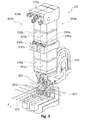
- Fig. 2a shows a perspective and schematic view of the pressing device 200 of a second embodiment of the inventive mesh welding system.
- An in Fig. 2a indicated longitudinal section through the pressing device 200 is in Fig. 2b shown.
- the pressing device 200 comprises a first pneumatic element 210 and a second pneumatic element 220, which are arranged one above the other so that their piston rods can act in series.
- Both pneumatic elements 210, 220 each comprise two cylinders 211.1, 211.2, 221.1, 221.2 arranged parallel to one another in the direction of the longitudinal wires to be welded (not visible), each having a duplex piston.
- Each of the four duplex pistons in total comprises an upper piston 214.1, 214.2, 224.1, 224.2 and a lower piston 213.1, 213.2, 223.1, 223.2 which in each case at one Piston rod 212.1, 212.2, 222.1, 222.2 is attached.
- the upper and lower pistons 213.1, 213.2, 223.1, 223.2, 214.1, 214.2, 224.1, 224.2 are cylindrical and each comprise a sealing ring 215.1, 215.2, 216.1, 216.2, 225.1, 225.2, 226.1, 226.2 which the outer surface of the respective piston 214.1, 214.2, 224.1, 224.2 against the respective cylinder 211.1, 211.2, 221.1, 221.2 airtight seals.
- Each cylinder 211.1, 211.2, 221.1, 221.2 is further divided by a concentric subdivision 217.1, 217.2, 227.1, 227.2 into an upper and a lower sub-cylinder.
- the respective subdivision 217.1, 217.2, 227.1, 227.2 has an opening in the middle, which serves as a guide for the piston rods 212.1, 212.2, 222.1, 222.2.
- the upper pistons 214.1, 214.2, 224.1, 224.2 divide the upper part cylinders into a first upper air chamber 251.1, 251.2, 261.1, 261.2 and into a first lower air chamber 252.1, 252.2, 262.1, 262.2.
- the lower pistons 213.1, 213.2, 223.1, 223.2 subdivide the lower part cylinders into a second upper air chamber, 253.1, 253.2, 263.1, 263.2 and into a second lower air chamber 254.1, 254.2, 264.1, 264.2.
- the first pneumatic element 210 comprises above the parallel juxtaposed cylinder 211.1. 211.2 a cuboid first connection piece 219 with a first compressed air connection 234 for the lowering or pressing of the first piston rods for 212.1, 212.2 and a compressed air connection 236 (FIG. Fig. 2a ) for raising or retracting the first piston rods 212.1, 212.2.
- the first compressed air connection 234 is connected via the first compressed air line 231 to a first feed valve (not visible), which can admit the compressed air for the lowering of the first piston rods 212.1, 212.2 via partially invisible air channels in the first upper air chambers 251.1, 251.2.
- the compressed air can pass from the first upper air chambers 251.1, 251.2 of the upper part cylinders via air ducts 250.1, 250.2 through the piston rods 212.1, 212.2 into the second upper air chambers 253.1, 253.2 of the lower part cylinder.
- the compressed air for lifting the piston rods 212.1, 212.2 passes through non-visible channels in the lower air chambers 252.1, 252.2, 254.1, 254.2.
- duplex pistons double the entire piston surface or almost double the maximum contact force of a cylinder.
- the second pneumatic element 220 is constructed similar to the first pneumatic element 210 and mounted directly above the first connecting piece 219, so that the second piston rods 222.1, 222.2 of the second pneumatic element 220 lie in the direct extension of the piston rods 212.1, 212.2 of the first pneumatic element 210 and thus in Series to the first piston rods 212.1, 212.1 are arranged and can make a contact connection with these.
- the first connection piece 219 of the first pneumatic element therefore, two circular openings are provided whose diameters are matched to the outer diameter of the second piston rods 222.1, 222.2.
- a likewise substantially parallelepiped-shaped connecting piece 229 for the second pneumatic element 220 with a compressed-air connection 235 for lowering the piston rods 222.1, 222.2 is arranged.
- the connecting piece 229 comprises on its upper side a mounting guide 239 for fastening the pressing device 200 to the mesh welding system.
- the second compressed air connection 235 is connected via the second compressed air line 232 to a second feed valve which controls the compressed air for lowering the second piston rods 222.1, 222.2 via air channels 237.1 and 237.2 in the connection block 229 into the first upper air chambers 261.1, 261.2 in the upper part cylinder of the second pneumatic element 220 can take in.
- the compressed air can pass from the first upper air chambers 261.1, 261.2 via air channels 260.1, 260.2 in the second piston rods 222.1, 222.2 into the second upper air chambers 263.1, 263.2 of the lower partial cylinder of the second pneumatic element 220.
- the second piston rods 222.1, 222.2 in the two parallel cylinders 221.1 and 221.2 are each moved or held in the rest position by a restoring spring 208.1 and 208.2 when no compressed air is present at the compressed air inlet 235.
- the piston rods 222. 1, 222.2 of the second pneumatic element 220 are at the upper stop.
- the return spring 208.1, 208.2 are designed as compression springs and in the first lower air chambers 262.1, 262.2 between the bottom surfaces of the upper piston 224.1, 224.2 and the subdivisions 208.1, 208.2 of the second pneumatic element 220 is arranged.
- the contact points serve to damp the shock which occurs when the second piston rods 222.1, 222.2 of the second pneumatic element 220 come into contact with the first piston rods 212.1, 212.2 of the first pneumatic element 210.
- first pneumatic unit 210 can be used or also the second pneumatic unit 220 can be connected and thus a higher contact force can be generated.
- the second pneumatic unit 220 is not active and in rest position and also does not require compressed air.
- the forces of the two pneumatic units add up.
- both the first and the pneumatic element is supplied with compressed air.
- the pressing device 200 welding forces of 0.6 kN to 6.7 kN can be covered with a width of 50 mm.
- the lower contact pressure of the pressing device is determined by the minimum force at which the pressing device can still move quickly and reliably despite friction.
- FIG. 3 shows a perspective and schematic view of an arrangement 350 with two parallel to each other arranged individual welding groups of a mesh welding plant according to the invention.
- Each individual welding group comprises in each case a pressing device 300a, 300b and an upper electrode holder with an upper electrode 301 and a lower electrode holder with a lower electrode 302.
- the two pressing devices 300a, 300b are arranged parallel to each other in the direction of the cross bars 303 to be welded.
- the pressing devices 300a, 300b respectively correspond to the pressing devices 200 according to FIGS FIGS.
- Each of these pressing devices 300a, 300b correspondingly comprises a first pneumatic element 310a, 310b and a second pneumatic element 320a, 320b and a first compressed air connection 334a, 334b for lowering the piston rods of the first pneumatic element, a second compressed air connection 335b for lowering the piston rods of the second pneumatic element 320a , 320b and a third compressed air connection 336a, 336b for lifting the piston rods of the first pneumatic element 310a, 310b.
- cross-wires 303 and longitudinal wires 375 of a grid are welded by electrical resistance welding.
- the longitudinal wires 375 are fed to the individual welding modules from the rear side between the two electrodes 301 and 302 in the longitudinal wire direction.
- the transverse wires 303 are inserted from the side in the transverse direction obliquely above the target position for welding and positioned via a non-visible magnetic positioning device.
- the welding operation is initiated and the positioned transverse rod 303 is pressed together with two longitudinal rods 375 for the welding operation by means of the pressing devices 300a, 300b by lowering the first piston rods of the first pneumatic element 310a, 310b with the upper electrodes 301 attached thereto at the lower end ,
- the welding current is conducted to the upper electrodes 301 in the form of alternating current of each unit via a flexible current band 379.
- the grid wires are heated by electric current to welding temperature and cross wires 303 and longitudinal wires 375 by simultaneous action of the contact force cohesively connected to each other.
- the second pneumatic elements 320a, 320b are activated.
- the mesh welding systems can, of course, comprise further pressing devices.
- a mesh welding system was created, which makes it possible to weld bars in a large power range cost-effectively. It is further noted that a method has been provided which allows cost-effective welding of bars in a large range of force. In addition, it should be noted that a kit has been created, which makes it possible in a simple and cost-effective manner upgrade mesh welding systems to expand their power range.
Landscapes
- Engineering & Computer Science (AREA)
- Mechanical Engineering (AREA)
- Manufacturing & Machinery (AREA)
- Resistance Welding (AREA)
Abstract
Description
- Die Erfindung betrifft eine Gitterschweissanlage mit einer Anpressvorrichtung für mindestens ein Werkzeug der Gitterschweissanlage. Die Anpressvorrichtung umfasst ein erstes Pneumatikelement mit mindestens einer ersten Kolbenstange, welche so ausgestaltet ist, dass sie mit einem der Werkzeuge der Gitterschweissanlage in Wirkverbindung gebracht werden kann. Ferner betrifft die Erfindung ein Verfahren zum Schweissen von Gitterstäben sowie einen Bausatz zur Aufrüstung einer Gitterschweissanlage.
- Eine Gitterschweissanlage verschweisst Längs- und Querstäbe zu einem Gitter. Beim Schweissen werden die zu verschweissenden Gitterdrähte zusammengepresst und mit einem definierten Strom erhitzt, welcher über die zu verschweissende Verbindungsstelle der Gitterdrähte fliesst.
- Durch das gleichzeitige Einwirken der Temperatur und der Anpresskraft werden die Gitterstäbe stoffschlüssig miteinander verbunden. Die optimale Anpresskraft für den Schweissvorgang ist dabei abhängig von den Gitterdrahtdurchmessern und der Materialbeschaffenheit der zu verschweissenden Gitterdrähte. Zudem ist es von Vorteil, wenn die Kraftquelle während des Prozesses nachsetzen kann, um die Anpresskraft während der Prozessdauer aufrechterhalten zu können. Üblicherweise werden Pneumatikpressen zum Verpressen der Gitterstäbe verwendet, für höhere Kraftbereiche jedoch auch Hydraulikpressen. Die Pneumatik- und die Hydraulikpressen ermöglichen es einerseits die Anpresskraft während des gesamten Prozesses aufrechtzuerhalten, andererseits die Anpresskraft an den Drahtdurchmesser anzupassen.
- Soweit es der erforderliche Kraftbereich zulässt, werden daher Pneumatikpressen eingesetzt. Allerdings ist der Kraftbereich einer üblichen Pneumatikpresse begrenzt, denn Pneumatikpressen, welche für hohe Kräfte geeignet sind, bewegen sich bei kleinen Anpresskräften nicht mehr schnell und zuverlässig. Daher müssen die Pneumatikpressen bei einem Wechsel von einem Gitterdrahtdurchmesser auf einen anderen häufig umgerüstet werden, was einen hohen Zeit- und Arbeitsaufwand bedeutet. Die Hydraulikpressen erlauben das Aufbringen hoher Anpresskräfte und die Abdeckung grosser Kraftbereiche. Jedoch ist der Einsatz von Hydraulikpressen sehr aufwendig und auch mit Schmutz durch Ölleckagen verbunden.
- Aufgabe der Erfindung ist es, eine dem eingangs genannten technischen Gebiet zugehörende Gitterschweissanlage zu schaffen, welche mindestens einen Nachteil des Bekannten überwindet und es insbesondere ermöglicht, in einem grossen Kraftbereich kosteneffizient Gitterstäbe verschweissen zu können.
- Die Lösung der Aufgabe ist durch die kennzeichnenden Merkmale der unabhängigen Ansprüche definiert. Gemäss der Erfindung umfasst die Gitterschweissanlage eine Anpressvorrichtung für mindestens ein Werkzeug der Gitterschweissanlage. Dabei umfasst die Anpressvorrichtung ein erstes Pneumatikelement mit mindestens einer ersten Kolbenstange, welche so ausgestaltet ist, dass sie mit einem der Werkzeuge der Gitterschweissanlage in Wirkverbindung gebracht werden kann. Die Anpressvorrichtung umfasst ferner ein zweites Pneumatikelement mit mindestens einer zweiten Kolbenstange, welche so ausgestaltet ist, dass sie mit dem ersten Pneumatikelement, insbesondere mit der ersten Kolbenstange in Wirkverbindung gebracht werden kann. Dabei sind das erste und das zweite Pneumatikelement so angeordnet, dass die erste(n) und zweite(n) Kolbenstange(n) durch eine translatorische Bewegung in ihrer Längsrichtung (Z) eine gemeinsame Anpresskraft ausüben können.
- Durch die Erfindung kann ein grösserer Kraftbereich mit derselben Anpressvorrichtung abgedeckt werden. Es kann ein grösserer Durchmesserbereich an Gitterdrähten auf der Gitterschweissanlage verschweisst werden, ohne dass umgerüstet werden muss. Es kann dadurch sowohl die Anpresskraft nur von dem ersten Pneumatikelement aufgebracht werden oder gleichzeitig vom ersten und vom zweiten Pneumatikelement. In einem unteren Kraftbereich kann die Anpresskraft nur von dem ersten Pneumatikelement aufgebracht werden und die Wirkverbindung zwischen der (den) ersten Kolbenstange(n) und der (den) zweiten Kolbenstange(n) unterbrochen sein. In diesem Fall wirkt die Reibung des zweiten Pneumatikelements beim Anpressen nicht der Anpresskraft entgegen bzw. bei einer Abhebebewegung in entgegengesetzter Richtung nicht der Abhebebewegung entgegen bzw. nicht auf eine translatorische Bewegung der erste(n) Kolbenstange(n) des ersten Pneumatikelements zurück.
- Dadurch lässt sich die Anpressvorrichtung auch mit geringen Anpresskräften betreiben und damit die Gitterschweissanlage wesentlich flexibler und kostengünstiger einsetzen. Zudem muss in einem unteren Kraftbereich eine geringere Masse bewegt werden, so dass kleinere Kraftspitzen beim Aufsetzen der Anpressvorrichtung auf den zu verschweissenden Gitterstäben entstehen. Die Anpressvorrichtung kann zudem durch die geringere bewegte Masse schneller arbeiten. Gleichzeitig kann der Luftverbrauch im unteren Kraftbereich gesenkt werden.
- Es ist auch möglich, dass eine Anordnung aus einem ersten- und einem zweiten Pneumatikelement mit mehreren Werkzeugen eine Wirkverbindung herstellen kann. Beispielsweise können mehrere Elektroden bezüglich einer translatorischen Bewegung in ihrer Längsachse mit der (den) ersten Kolbenstange(n) wirkverbunden sein. Durch diese Anordnung lassen sich insbesondere engmaschige Gitter verschweissen.
- Ein erstes/zweites Pneumatikelement kann mehrere parallel zueinander angeordnete Pneumatikzylinder mit jeweils einer erster/zweiten Kolbenstange umfassen, an welcher jeweils ein Kolben angeordnet ist.
- In einer besonderen Ausführungsform sind die Pneumatikzylinder des ersten und/oder zweiten Pneumatikelements als Duplexzylinder mit einem Duplexkolben ausgebildet. Ein Duplexzylinder ist in zwei in Richtung der Längsachse der Kolbenstange hintereinander liegende Teilzylinder unterteilt. Ein Duplexkolben umfasst dabei zwei über die Kolbenstange verbundene Kolben die jeweils in einem Teilzylinder angeordnet sind.
- In einer weiteren besonderen Ausführungsform sind die Pneumatikzylinder des ersten und des zweiten Pneumatikelements als Triplexzylinder mit einem Triplexkolben ausgebildet.
- In einer besonderen Ausführungsform sind die Pneumatikelemente so ausgestaltet, dass sie getrennt voneinander steuerbar sind. Insbesondere sind sie so ausgestaltet, dass das erste Pneumatikelement eine erste Steuereinrichtung umfasst und das zweite Pneumatikelement eine zweite Steuereinrichtung umfasst, welche jeweils separat ansteuerbar sind. Durch die getrennte Ansteuerung können die Pneumatikelemente separat dazugeschaltet werden. Sie können dazugeschaltet werden, wenn dazu Bedarf besteht.
- Dadurch, dass beide Pneumatikelemente separat dazugeschaltet werden können, kann ohne einen Umrüstvorgang der Anpresskraftbereich der Anpressvorrichtung vergrössert oder verkleinert werden. Es kann dabei automatisch der Anpresskraftbereich auf andere Werkstücke und/oder Prozessparameter umgestellt oder auch während der Bearbeitung umgestellt werden.
- Alternativ gibt es nur eine gemeinsame Ansteuerung für das erste und das zweite Pneumatikelement. Die Gitterschweissanlage kann dann jedoch so umgerüstet werden, dass entweder beide oder nur ein Pneumatikelement alleine angesteuert werden bzw. aktiv sind.
- Dies kann beispielsweise durch Umstecken der Druckluftleitungen oder auch durch Umschaltventile erfolgen. Es kann auch das erste oder das zweite Pneumatikelement, je nachdem welches nicht benötigt wird, von der Druckluftversorgung abgeklemmt oder verbunden werden, beispielsweise mittels eines Handschalters. Es kann jedoch auch ein Pneumatikelement von der Ansteuerung getrennt bzw. mit der Ansteuerung verbunden werden, so dass entweder beide oder nur eines der beiden Pneumatikelemente aktiv am Kraftaufbau beteiligt sein können.
- Insbesondere können dann beide Pneumatikelemente zusammen ansteuerbar sein, oder das erste Pneumatikelement alleine.
- Alternativ kann auch nur das erste oder das zweite Pneumatikelement alleine angesteuert werden, während das andere der beiden Pneumatikelemente mit einem konstanten Luftdruck beaufschlagbar sein kann. Insbesondere kann das erste Pneumatikelement ansteuerbar sein, während das zweite mit einem konstanten Luftdruck beaufschlagt wird. Dadurch kann der Bereich der Anpresskraft erhöht werden, ohne dass beide Pneumatikelemente ansteuerbar sein müssen.
- Es ist jedoch auch möglich, dass die Druckluftzufuhr des ersten und/oder des zweiten Pneumatikelement gedrosselt ist, so dass es nur zu einem Teil zur Anpresskraft beiträgt.
- In einer besonderen Ausführungsform weist mindestens eine erste oder eine zweite Kolbenstange eine Kontaktstelle zur Herstellung einer Kontaktverbindung auf, welche ausgelegt ist um die mindestens eine erste Kolbenstange in Wirkverbindung mit einer zweiten Kolbenstange zu bringen. Insbesondere ist die Kontaktstelle aus Messing.
- Durch die Kontaktstelle ist es einfach möglich, eine Wirkverbindung zwischen der ersten und der zweiten Kolbenstange in Form einer Kontaktverbindung herzustellen und dadurch eine Anpresskraft von der zweiten Kolbenstange auf die erste Kolbenstange zu übertragen, wenn Bedarf dazu besteht, oder zu trennen, wenn kein Bedarf dazu besteht. Es ist kein zusätzlicher Mechanismus zum Herstellung oder zum Trennen der Kontaktverbindung notwendig.
- In einer besonderen Ausführungsform weisen alle ersten oder zweiten Kolbenstangen eine Kontaktstelle zur Herstellung eine Kontaktverbindung auf.
- Alternativ kann anstelle der Kontaktverbindung auch eine feste Verbindung zwischen der (den) ersten und der (den) zweiten Kolbenstange(n) hergestellt werden. Beispielsweise kann eine lösbare kraftschlüssige Verbindung angewendet werden, wie beispielsweise eine Klemmverbindung. Es ist aber auch genauso möglich, formschlüssige Verbindungen, beispielsweise über einen Bolzen oder eine Schnappverbindung zu realisieren. In diesen Fällen muss jedoch jeweils die Verbindung zwischen der ersten und der zweiten Kolbenstange beim Herstellen und/oder Trennen der Wirkverbindung aktiv hergestellt oder gelöst werden, beispielsweise durch einen manuellen Eingriff oder auch durch ein automatisiertes mechanisches bzw. mechatronisches Betätigungsmittel.
- Es können jedoch auch andere Kraftübertragungsmechanismen in Frage kommen. Beispielsweise kann eine Verbindung über eine magnetische oder elektromagnetische Kraft erfolgen. Es sind selbstverständlich auch Mischformen der zuvor genannten Verbindungsformen möglich.
- Die Verwendung einer Kontaktstelle aus Messing ist besonders vorteilhaft, da Messing verschleissresistent und gleichzeitig relativ weich ist und dadurch der Stoss bei der Herstellung der Kontaktverbindung klein gehalten werden kann. Dadurch dass die Kontaktstelle an der (den) ersten oder zweiten Kolbenstange(n) im Vergleich zu den Kolbenstangen, die üblicherweise aus Stahl hergestellt sind, weich ist, kann der Verschleiss an der zweiten oder ersten Kolbenstange, welche mit der jeweiligen ersten oder zweiten Kolbenstange in Wirkverbindung gebracht werden kann, ebenfalls reduziert werden.
- In einer bevorzugten Ausführungsform ist die Kontaktstelle austauschbar, so dass die Lebensdauer der Anpressvorrichtung erhöht oder auch an das Schweissgut angepasst werden kann.
- Es sind jedoch auch Kontaktstellen aus anderen Materialen möglich, insbesondere Materialen, die dämpfend sind und somit einen Stoss verringern, die aber auf der anderen Seite robust gegen Verschleiss sind. Es eignen sich neben Messing-Verbindungen auch andere Kupfer-Legierungen. Es können neben metallischen Werkstoffen auch Kunststoffe oder Keramiken verwenden werden. Insbesondere sind auch Kontaktstellen möglich, welche aus mehreren Materialen bestehen, wie beispielsweise aus Verbundwerkstoffen. Es können auch beide Kolbenstangen mit Kontaktstellen zum Herstellen einer Kontaktverbindung ausgestattet sein.
- In einer besonderen Ausführungsform sind die erste(n) und zweite(n) Kolbenstange(n) in Serie angeordnet.
- Durch die Anordnung in Serie, ergibt sich die Anpresskraft direkt aus der Summe der einzelnen Kräfte der Pneumatikelemente. Die Anpresskraft des zweiten Pneumatikelements wird dadurch immer über das erste Pneumatikelement auf das Werkstück übertragen. Dadurch ist eine Nachrüstung bestehender Maschinen einfach möglich, da die Schnittstelle zum Werkzeug bei einer Nachrüstung beibehalten werden kann.
- Insbesondere werden die erste(n) und zweite(n) Kolbenstange(n) auch geometrisch hintereinander in Serie angeordnet. Dadurch werden Kippmomente vermieden, welche sich beispielsweise bei einer quer zur Längsrichtung versetzten Anordnung ergeben können. Die Baubreite der Anpressvorrichtung bei einer vorgegebenen Anpresskraft kann durch die Anordnung in Serie klein gehalten werden, wodurch auch engmaschige Gitter geschweisst werden können. Zudem können auch ähnliche Komponenten für das erste und das zweite Pneumatikelement verwendet werden, wodurch die Kosten klein gehalten werden können.
- Alternativ lassen sich die erste(n) und zweite(n) Kolbenstange(n) in einer Serie anordnen, wobei jedoch die Kolbenstangen quer zur Längsrichtung (Z) zueinander versetzt sind.
- In einer weiteren alternativen Ausführungsform sind die erste(n) und zweite(n) Kolbenstange(n) parallel zueinander angeordnet, das heisst, das sowohl die erste(n) und die zweite(n) Kolbenstange(n) eine Anpresskraft auf das Werkzeug auszuüben vermögen, ohne dass jedoch der Kraftfluss der zweiten Kolbenstange(n) über die erste(n) Kolbenstange(n) geht.
- In einer besonderen Ausführungsform ist das Werkzeug eine Elektrode, welche insbesondere bezüglich einer translatorischen Bewegung in ihrer Längsachse mit der (den) ersten Kolbenstange(n) wirkverbunden ist.
- Dadurch, dass das Werkzeug eine Elektrode ist, welche mit der ersten Kolbenstange wirkverbunden ist, kann die Elektrode sehr schnell angepresst und wieder zurückgezogen werden, wodurch eine sehr schnelle Bearbeitung, insbesondere eine sehr schnelle diskontinuierliche Bearbeitung möglich ist, wie das beim Schweissen von Gitterstäben der Fall ist. Insbesondere können die Anpresskräfte der Elektrode direkt und damit genau aufgebracht werden. Das Werkzeug kann auch eine Strombrücke umfassen, an deren Ende Elektroden angeordnet sind, wodurch serielles Schweissen möglich wird.
- In einer alternativen Ausführungsform ist das Werkzeug ein Anpressmittel, welches die zu verschweissenden Gitterdrähte aneinanderpresst, wie beispielsweise eine Rolle.
- In einer besonderen Ausführungsform weist das zweite Pneumatikelement ein Rückhaltemittel auf, welches ausgestaltet ist, eine Rückstellkraft auf die zweite(n) Kolbenstange(n) auszuüben. Insbesondere umfasst das zweite Pneumatikelement mindestens eine Rückstellfeder, welche so ausgestaltet ist, dass sie auf die zweite(n) Kolbenstangen eine Rückstellkraft ausübt, welche translatorisch zur Längsachse der zweite(n) Kolbenstange(n) wirkt.
- Die Rückstellkraft des Rückstellelements wirkt in Längsrichtung (Z) der Anpresskraft entgegen und vermag das zweite Pneumatikelement bzw. die zweite Kolbenstange in einer Ruheposition halten oder gar in diese zurückzuziehen.
- Dadurch muss auch dann keine Druckluft aufgewendet werden, um das zweite Pneumatikelement in der Ruheposition zu halten, wenn das zweite Pneumatikelement vertikal über dem ersten Pneumatikelement angeordnet ist.
- Das erste Pneumatikelement kann auch dann völlig unabhängig vom ersten Pneumatikelement betrieben werden.
- In einer besonderen Ausführungsform ist das Rückstellelement ein elektromagnetisches Stellelement.
- In einer weiteren besonderen Ausführungsform ist das Rückstellelement ein Permanentmagnet.
- Alternativ kann das zweite Pneumatikelement jedoch auch als Zweiwegpneumatikelement ausgeführt sein, so dass die zweite(n) Kolbenstange(n) in Längsrichtung (Z) entgegen der Richtung der Anpresskraft über Druckluft in der Ruheposition gehalten bzw. bewegt werden kann.
- In einer weiteren Alternativen Ausführungsform umfasst das zweite Pneumatikelement kein Rückstellelement.
- In einer besonderen Ausführungsform umfassen das erste und das zweite Pneumatikelement zum schnellen Aufbau der Anpresskraft jeweils wenigstens ein Vorschubventil, welches die Betätigung der ersten und der zweiten Kolbenstange(n) in Längsrichtung (Z) in Richtung der Anpresskraft ermöglicht. Als Vorschubventil wird im Rahmen der Erfindung eines Pneumatikelements bezeichnet, durch welches Druckluft in die Luftkammern des Pneumatikelements eingelassen werden kann, in welchen ein Überdruck ein Ausfahren der Kolbenstange(n) in Richtung der zu verschweissenden Gitterstäbe bewirkt oder eine Erhöhung des Anpressdrucks bzw. Anpresskraft bewirkt. Dadurch, dass das erste und das zweite Pneumatikelement jeweils ein Vorschubventil umfasst, kann die Druckluft schneller eingelassen werden als mit einem gemeinsamen Vorschubventil. Vorzugsweise umfassen beide Vorschubventile jeweils einen Entlüftungsanschluss, wodurch der Anpressdruck bzw. die Anpresskräfte auch schneller abgebaut werden können.
- Als Vorschubventile mit Entlüftunganschluss können beispielsweise 3/2-Wegeventile verwendet werden.
- Da das erste und das zweite Pneumatikelement ein eigenes Vorschubventil umfassen, können sie auch separat angesteuert werden.
- Alternativ werden das erste und das zweite Pneumatikelement von einem gemeinsamen Vorschubventil angesteuert.
- In einer besonderen Ausführungsform umfasst das erste Pneumatikelement wenigstens ein Rückzugventil, dass eine Betätigung der erste(n) Kolbenstange(n) in Längsrichtung (Z) in eine der Anpresskraft entgegengesetzten Richtung ermöglicht. Als ein Rückzugventil wird im Rahmen der Erfindung ein Pneumatikventil bezeichnet, durch welches Druckluft in die Luftkammern des Pneumatikelements eingelassen werden kann, in welchen ein Überdruck ein Einfahren der Kolbenstange(n) von den zu verschweissenden Gitterstäbe weg oder eine Verringerung des Anpressdrucks bzw. Anpresskraft bewirkt. Die resultierende Kraft auf die erste(n) Kolbenstange(n) bewirkt also dass die erste(n) Kolbenstange(n) vom Werkstück wegbewegt bzw. zurückgezogen wird. Das Pneumatikelement kann folglich als doppelwirkendes Pneumatikelement betrieben werden.
- Durch das Rückzugventil des ersten Pneumatikelements ist ein schnelles Rückziehen der ersten Kolbenstange(n) und, falls die zweite(n) Kolbenstange(n) sich in Wirkverbindung mit der (den) ersten Kolbenstange(n) befindet, auch der zweiten Kolbenstange(n) möglich.
- Als Rückzugventile können beispielsweise auch 3/2-Wegeventile mit einem Entlüftungsanschluss verwendet werden.
- Alternativ kann das Rückzugventil mit dem Ausfahrventil des ersten Pneumatikelements in Form eines Wegeventils kombiniert werden, beispielsweise in Form eines 4/2-Wegeventils, eines 4/3-Wegeventils oder 5/2-Wegeventils.
- In einer besonderen Ausführungsform umfasst die Gitterschweissanlage ein Steuermodul, welches so ausgestattet ist, dass es die Steuereinrichtungen der Pneumatikelemente getrennt anzusteuern vermag und das Vorschub- und das Rückzugventil des ersten Pneumatikelements mit dem Vorschubventil des zweiten Pneumatikelements zu synchronisieren vermag. Durch die getrennte Ansteuerung der Steuereinrichtungen, insbesondere der Vorschub- bzw. Rückzugventile ist eine optimierte Bewegungsführung der Kolbenstange(n) und damit des Werkzeugs und auch des Anpressdrucks bzw. der Anpresskraft möglich. Beispielsweise kann das zweite Pneumatikelement mit einer Zeitverzögerung zum ersten Pneumatikelement ausgefahren werden, um den Stoss des Werkzeugs zu verringern. Zudem kann eine gewisse Anpresskraft erst im Laufe des Schweissprozesses erforderlich sein, so dass das zweite Pneumatikelement erst später aktiviert werden kann. Umgekehrt kann es vorteilhaft sein, während des Schweissvorgangs mit dem Vorschubventil des zweiten Pneumatikelements die Druckluftzufuhr abzustellen um die Anpresskraft zu reduzieren und die zweite(n) Kolbenstange(n), beispielsweise durch das Rückstellelement, in die Ruheposition zurückzustellen. Die Synchronisierung kann auch das Vorhalten von Stellzeiten beinhalten, welche es ermöglicht den Schweisszyklus zeitlich zu optimieren. Besonders bevorzugt ist, dass die Synchronisierung programmierbar ist. Es ist jedoch auch möglich, die Synchronisierung durch Hardwarekomponenten wie elektrische oder mechanische Verzögerungsglieder zu realisieren.
- Alternativ können die Steuereinrichtungen der Pneumatikelemente nur gemeinsam angesteuert werden.
- In einer besonderen Ausführungsform umfasst die Gitterschweissanlage eine Stabzuführung, zum getakteten Zuführen von zu verschweissenden Stäben, und insbesondere eine Positioniereinrichtung zum Positionieren der zu verschweissenden Stäbe in einem Werkzeugbereich, insbesondere einer magnetischen Positioniereinrichtung.
- Durch die Positioniervorrichtung können quer liegende Gitterstäbe vor dem Verschweissen auf einen Anschlag gezogen und deren Lage überwacht werden, wodurch die Anlage mit erhöhter Taktzeit betrieben werden kann. In einer besonderen Ausführungsform kann durch die magnetische Positioniervorrichtung der Gitterdrahtdurchmesser erkannt und damit automatisch die Anpresskraft über die Anpressvorrichtung eingestellt werden.
- In einer besonderen Ausführungsform umfasst die Gitterschweissanlage eine Mehrzahl paralleler Anordnungen mit je dem ersten und dem zweiten Pneumatikelement.
- Eine Gitterschweissanlage verschweisst Längs- und Querstäbe zu einem Gitter. Die Mehrzahl der parallelen Anordnungen wird dabei bevorzugt in Richtung der zu verschweissenden Querdrähte angeordnet. Dadurch lässt sich die Gitterschweissanlage einfach an die zu fertigenden Gitter anpassen bzw. skalieren. Dabei kann vorgesehen werden, dass jeweils mehrere parallele Anordnungen zu einer Gruppe angeordnet ist, welche mit einem Werkzeug, beispielsweise einer Elektrode eine Wirkverbindung herstellen können. Dadurch kann die Anpresskraft pro Werkzeug respektive pro Elektrode oder Längsstab erhöht werden.
- Ein weiterer Aspekt der vorliegenden Erfindung ist ein Verfahren zum Schweissen von Gitterstäben. Das Verfahren umfasst die Schritte:
- a) Bereitstellen einer erfindungsgemässen Gitterschweissanlage gemäss Anspruch 1;
- b) Zuführen und Positionieren von zu verschweissenden Stäben in einen Werkzeugbereich der Gitterschweissanlage;
- c) Aktivieren des ersten Pneumatikelements zur Zuführung des Werkzeugs in den Werkzeugbereich mit einer ersten Anpresskraft F, und Auslösen eines Schweissstroms, insbesondere eines Wechselstroms, und,
- d) eventuell aktivieren des zweiten Pneumatikelements zur Addition einer zweiten Anpresskraft F2 an die erste Anpresskraft F1.
- Die Aktivierung des zweiten Pneumatikelements ist dabei abhängig von der benötigten Anpresskraft. Kann die notwendige Anpresskraft vom ersten Pneumatikelement abgedeckt werden, wird bevorzugt nur das erste Pneumatikelement aktiviert. Vor allem bei kleinen Anpresskräften kann die Anpresskraft dadurch präziser eingestellt werden, da die Reibung des zweiten Pneumatikelements sich nicht auf die Anpresskraft auswirkt.
- Alternativ ist es auch möglich, nur das zweite Pneumatikelement zu aktivieren.
- In einer besonderen Ausführungsform werden die Schritte c) und d) des Verfahrens synchronisiert.
- Es kann vorteilhaft sein, die Schritte c) und d) zeitlich zu synchronisieren, bzw. mit einem bestimmten Zeitversatz auszuführen, um beispielsweise den Stoss beim Auftreffen der ersten Kolbenstange(n) auf das Werkzeug der Gitterschweissanlage und/oder des Werkzeugs auf die Gitterstäbe zu reduzieren. Zudem kann, sofern eine kleinere Anpresskraft am Anfang eines Schweisszyklus benötigt wird, zu Beginn nur das erste Pneumatikelement aktiviert ist und das zweite, falls erforderlich erst aktiviert wird, wenn im Verlauf des Zyklus eine höhere Anpresskraft erforderlich ist oder auch um die Anpresskraft trotz des sich veränderten Abstands der miteinander verschmelzenden Gitterdrähte die Anpresskraft nachsetzen zu können. Die am Anfang des Prozesses geringere Anpresskraft kann somit präziser aufgebaut werden.
- Umgekehrt kann es auch vorteilhaft sein, dass das zweite Pneumatikelement vor dem ersten Pneumatikelement deaktiviert wird, um am Ende des Schweissprozesses eine kleinere definierte Prozesskraft einzustellen und damit die Gittergeometrie und die Verschweissung zu optimieren.
- Die Synchronisierung kann dabei sowohl zeitbasiert sein als auch ereignisgesteuert. Beispielsweise kann bei Überschreiten einer bestimmten Anpresskraftschwelle oder auch einer Schwelle des Schweissstroms das zweite Pneumatikelement aktiviert oder auch deaktiviert werden.
- Die Synchronisierung kann auch verwendet werden, um elektrische und mechanische Zeitkonstanten oder Signallaufzeiten zu kompensieren oder abzustimmen.
- Alternativ kann jedoch eine gleichzeitige Ansteuerung der beiden Pneumatikelemente verwendet werden.
- In einer besonderen Ausführungsform wird die Summe der Anpresskräfte abhängig von Durchmesser und/oder Material der zu verschweissenden Stäbe eingestellt, insbesondere dergestalt, dass ein allfälliges plastisches Verformen durch ein Einwirken der Anpresskräfte auf die Stäbe im Wesentlichen verhindert wird.
- Durch das Abstimmen der Anpresskraft kann einerseits die Gitterqualität in Bezug auf die Verschweissstellen sowie auf die geometrische Genauigkeit optimiert und auch in Abhängigkeit des Schweissstromes die Schweisszeit optimiert werden.
- In einer besonderen Ausführungsform wird der Schweissstrom über einen Zeitraum X aufrechterhalten und die Anpresskraft F1 und/oder F2 über diesen Zeitraum variiert, insbesondere erhöht.
- Es kann somit der Verlauf der resultierenden Anpresskraft über den Schweisszyklus variiert und auf den Durchmesser und/oder das Material der Gitterstäbe abgestimmt werden.
- Alternativ kann die Anpresskraft F1 und/oder F2 über diesen Zeitraum konstant gehalten werden, wobei die Kolbenstange(n) während des Schweissvorgangs nachsetzen, um die Anpresskraft F1 und/oder F2 oder auch die Summe der beiden Kräfte konstant zu halten.
- In einer besonderen Ausführungsform, wird der Schweissstrom während des Zeitraums X in seiner Amplitude und/oder Frequenz variiert.
- Ein weiterer Aspekt der vorliegenden Erfindung ist ein Bausatz zur Aufrüstung einer Gitterschweissanlage zu einer erfindungsgemässen Gitterschweissanlage wie sie durch die kennzeichnenden Merkmale des unabhängigen Anspruchs 1 definiert ist. Der Bausatz umfasst zur Aufrüstung der Gitterschweissanlage:
- a) Ein erstes Pneumatikelement mit mindestens einer ersten Kolbenstange, welche so ausgestaltet ist, dass sie mit einem der Werkzeuge der Gitterschweissanlage in Wirkverbindung gebracht werden kann;
- b) ein zweites Pneumatikelement mit mindestens einer zweiten Kolbenstange welche so ausgestaltet ist, dass sie mit der ersten Kolbenstange in Wirkverbindung gebracht werden kann, und
- c) ein Verbindungselement, welches ausgelegt ist, das erste Pneumatikelement mit dem zweiten Pneumatikelement in Wirkverbindung zu bringen und welches insbesondere eine Kontaktstelle zur Herstellung einer Kontaktverbindung aufweist, welche ausgelegt ist um die erste Kolbenstange in Wirkverbindung mit der zweiten Kolbenstange zu bringen, insbesondere wobei die Kontaktstelle aus Messing ist.
- Das erste Pneumatikelement umfasst bevorzugt zwei parallel zueinander angeordnete Pneumatikzylinder mit jeweils einer ersten Kolbenstange und einem ersten Kolben und das zweite Pneumatikelement umfasst bevorzugt zwei parallel zueinander angerordnete Pneumatikzylinder mit jeweils einer zweiten Kolbenstange und einem zweiten Kolben.
- In einer besonderen Ausführungsform sind die Pneumatikzylinder des ersten und/oder zweiten Pneumatikelements als Duplexzylinder ausgebildet und die Kolben als Duplexkolben. Ein Duplexzylinder ist in zwei in Richtung der Längsachse der Kolbenstange hintereinander liegende Teilzylinder unterteilt. Ein Duplexkolben umfasst dabei zwei über die Kolbenstange verbundene Kolben die jeweils in einem Teilzylinder angeordnet sind.
- In einer weiteren besonderen Ausführungsform sind die Pneumatikzylinder des ersten und des zweiten Pneumatikelements als Triplexzylinder mit einem Triplexkolben ausgebildet.
- Im Folgenden wird die Erfindung anhand von Figuren und konkreter Ausführungsbeispiele näher erläutert, ohne allerdings auf diese eingeschränkt zu sein.
- Aus der Detailbeschreibung und der Gesamtheit der Patentansprüche können sich zudem weitere vorteilhafte Ausführungsformen und Merkmalskombinationen der Erfindung ergeben.
- Die zur Erläuterung des Ausführungsbeispiels verwendeten Zeichnungen zeigen:
- Fig. 1a
- Blockdiagramm eines ersten Ausführungsbeispiels der erfindungsgemässen Gitterschweissanlage;
- Fig. 1b
- Prinzipskizze der Anpressvorrichtung des ersten Ausführungsbeispiels der erfindungsgemässen Gitterschweissanlage;
- Fig. 2a
- Perspektivische und schematische Ansicht der Anpressvorrichtung eines zweiten Ausführungsbeispiels der erfindungsgemässen Gitterschweissanlage;
- Fig. 2b
- Schnittansicht und schematische Ansicht der Anpressvorrichtung gemäss
Fig. 2a ; - Fig. 3
- Perspektivische und schematische Ansicht zweier parallel angeordneter Einzelschweissgruppen eines dritten Ausführungsbeispiels der erfindungsgemässen Gitterschweissanlage.
- Grundsätzlich sind in den Figuren gleiche Teile mit gleichen Bezugszeichen versehen.
-
Fig. 1a zeigt ein Blockdiagramm eines ersten Ausführungsbeispiels der erfindungsgemässen Gitterschweissanlage 1 mit einer Anpressvorrichtung 100. Der funktionelle Aufbau der Anpressvorrichtung ausFig. 1a ist inFig. 1b in Form einer Prinzipskizze etwas detaillierter dargestellt. - Die Gitterschweissanlage 1 umfasst ein Steuermodul 2, welches die Ventile einer Ventilinsel 3 ansteuern und damit die Anpressvorrichtung 100 mit einem ersten Pneumatikelement 110 und einem zweiten Pneumatikelement 120 betätigen kann, wobei das erste Pneumatikelement 110 und das zweite Pneumatikelement 120 übereinander in Serie angeordnet sind.
- Die Ventile der Ventilinsel 3 sind über eine elektrische Steuerleitung 4 mit dem Steuermodul verbunden und werden über dieses angesteuert. Über die Anpressvorrichtung 100 kann eine am ersten Pneumatikelement 110 befestigte obere Elektrode 101 in Richtung einer unteren Elektrode 102 abgesenkt und damit ein Querstab 103 mit einem Längsstab 175 zum Verschweissen zwischen der oberen Elektrode 101 und der unteren Elektrode 102 mit einer bestimmten Anpresskraft verpresst werden.
- Die Ventilinsel 3 wird über eine Druckluftleitung 5 mit Druckluft versorgt und umfasst ein erstes Vorschubventil 6 zum Absenken der ersten Kolbenstange 112 des ersten Pneumatikelements 110 in Anpressrichtung, ein zweites Vorschubventil 7 zum Absenken der zweiten Kolbenstange 122 des zweiten Pneumatikelements 120 in Anpressrichtung sowie ein Rückzugventil 8 zum Anheben der ersten Kolbenstange 112 des ersten Pneumatikelements 120 in der zur Anpressrichtung Z entgegengesetzten Richtung, z.B. nach einem Schweissvorgang. Das erste Vorschubventil 6 ist über einen ersten Luftkanal 131 mit dem Luftanschluss 134 für das Absenken der ersten Kolbenstange 112 des ersten Pneumatikelements 110, das zweite Vorschubventil 7 über einen zweiten Luftkanal 132 mit dem Lufteinlass 135 für das Absenken der zweiten Kolbenstange 122 des zweiten Pneumatikelements 120 und das dritte Einlassventil 8 mit dem dritten Luftkanal 133 mit dem Lufteinlass 136 für das Anheben der zweiten Kolbenstange 122 des ersten Pneumatikelements 120 verbunden.
- Das erste Pneumatikelement 110 umfasst ersten Zylinder 111, in welchem eine erste Kolbenstange 112 zentrisch angeordnet ist und in Richtung der Längsachse Z frei beweglich ist. Am oberen Ende der ersten Kolbenstange 112 ist ein zylindrischer erster Kolben 113 angeordnet, welcher den Innenraum des ersten Zylinders 111 in eine erste obere Luftkammer 114 und in eine untere Luftkammer 115 aufteilt. Der erste Zylinder 111 hat an der oberen Grundfläche, welche an die obere Luftkammer 116 angrenzt, eine zentrische kreisrunde obere Öffnung 116, durch die eine zweite Kolbenstange 122 des zweiten Pneumatikelements 130 hindurch auf die Kolbenoberseite der ersten Kolbens 113 zu drücken vermag. Der Durchmesser der oberen Kolbenstange 122 ist dabei an den Durchmesser der oberen Öffnung 116 angepasst, um ein Entweichen der Luft aus der Öffnung zu verhindern. An der unteren Grundfläche des ersten Zylinders 111 ist eine ebenfalls konzentrische kreisrunde untere Öffnung 117 angeordnet, durch welche die erste Kolbenstange 112 aus dem Zylinder 111 hinausragt. Am unteren Ende der ersten Kolbenstange 112, ist die Werkzeugschnittstelle 107 angeordnet, an welcher eine obere Elektrode 101 befestigt ist. Durch Einlassen von Druckluft über den ersten Luftkanal 131 und den ersten Lufteinlass 134 in die erste obere Luftkammer 115 wird die erste Kolbenstange 112 abgesenkt und eine Anpresskraft erzeugt, wenn die Elektrode in Wirkverbindung mit dem Querstab 103 gerät. Entsprechend kann durch Einlassen von Druckluft in die untere Luftkammer 115 über den dritten Luftkanal 133 und den dritten Lufteinlass 136 die erste Kolbenstange 112 zusammen mit der oberen Elektrode 101 nach oben bewegt werden.
- Das zweite Pneumatikelement 120 ist ähnlich aufgebaut wie das erste Pneumatikelement 110. Es umfasst einen zweiten Zylinder 121, in welchem eine zweite Kolbenstange 122 zentrisch angeordnet ist und in Richtung der Längsachse Z frei beweglich ist. Am oberen Ende der zweiten Kolbenstange 122 ist ein zylindrischer zweiter Kolben 123 befestigt, welcher den Innenraum des zweiten Zylinders 121 in eine zweite obere Luftkammer 124 und in eine zweite untere Luftkammer 125 aufteilt. Der zweite Zylinder 121 hat an der unteren Grundfläche, welche an die untere Luftkammer 125 angrenzt, eine zentrische kreisrunde untere Öffnung 127, durch die die Kolbenstange 122 des zweiten Pneumatikelements 120 hindurch auf die Kolbenoberseite der ersten Kolbens 113 zu drücken vermag. Durch Einlassen von Druckluft über den zweiten Luftkanal 132 und den zweiten Lufteinlass 135 in die zweite obere Luftkammer 125 kann die zweite Kolbenstange 112 abgesenkt und dadurch über eine Kontaktstelle 106 aus Messing eine Kontaktverbindung mit dem ersten Kolben 113 hergestellt werden, indem die Kontaktstelle 106 auf die Kolbenoberfläche des ersten Kolbens 113 gedrückt wird. Die zylindrische Kontaktstelle 106 aus Messing ist an der Unterseite in direkter Verlängerung der zweiten Kolbenstange 122 angebracht, um bei der Herstellung der Kontaktverbindung zwischen dem ersten Kolben 112 respektive den an der Kolbenstange 112 befestigten Kolben 113 und der zweiten Kolbenstange 122 den Stoss und die Kraftspitzen und damit auch den Verschleiss zu reduzieren. Die Kolbenstangen 112, 122 und die Kolben 113,123 sind in aus Stahl gefertigt und damit härter als Messing. Jedoch können sie auch aus anderen Materialien gefertigt sein, welche den rauen Anforderungen in einer Schweissanlage gerecht werden.
- In der zweiten unteren Luftkammer 125 ist eine Rückstellfeder 108 angebracht, welche die zweite Kolbenstange 122 in eine Ruheposition in einen Endanschlag zurückbewegt bzw. die Kolbenstange anhebt und in den zweiten Zylinder 121 einfährt, wenn die obere Luftkammer 124 des zweiten Pneumatikelements 120 nicht mit Druckluft beaufschlagt wird. Dadurch wird auch die Kontaktverbindung zwischen der ersten Kolbenstange 112 und der zweiten Kolbenstange 122 aufgehoben. In diesem Fall trägt dann nur das erste Pneumatikelement 110 zur Bewegung der oberen Elektrode 101 bzw. zum Aufbau der Anpresskraft bei. Es muss auch weder beim Absenken respektive Anpressen noch beim Abheben die Reibung des ersten Pneumatikzylinders 120 überwunden werden. Ist die Kolbenstange 122 des zweiten Pneumatikelements 120 noch in einer abgesenkten Position, kann sie sowohl von der Rückstellfeder 108 als auch von der ersten Kolbenstange 112 angehoben bzw. in die Ruheposition bewegt werden. Ein eigener Lufteinlass für die untere Luftkammer 125 des zweiten Pneumatikelements 120 ist in der Regel nicht erforderlich, kann jedoch auch vorgesehen werden, falls die Anhebegeschwindigkeit erhöht werden sollte.
- Es ist zu beachten, dass jedes der beiden Pneumatikelemente 110, 120 ein eigenes Vorschubventil 6, 7 besitzt. Dadurch wird einerseits eine zeitverzögerte Ansteuerung der Pneumatikelemente ermöglicht, gleichzeitig kann aber auch die Druckluft in den beiden Zylinder 111, 121 schneller aufgebaut werden als mit einem gemeinsamen Vorschubventil.
- Es wird noch darauf hingewiesen, dass auch Entlüftungskanäle vorgesehen sind. Sie sind aber aus Gründen der Übersichtlichkeit nicht beschrieben und in den
Fig. 1a und 1b nicht dargestellt. -
Fig. 2a zeigt eine perspektivische und schematische Ansicht der Anpressvorrichtung 200 eines zweiten Ausführungsbeispiels der erfindungsgemässen Gitterschweissanlage. Ein inFig. 2a angedeuteter Längsschnitt durch die Anpressvorrichtung 200 ist inFig. 2b dargestellt. - Die Anpressvorrichtung 200 umfasst ein erstes Pneumatikelement 210 und ein zweites Pneumatikelement 220, die so übereinander angeordnet sind, dass ihre Kolbenstangen in Serie wirken können.
- Beide Pneumatikelemente 210, 220 umfassen jeweils zwei in Richtung der zu verschweissenden Längsdrähte (nicht sichtbar) parallel hintereinander angeordnete Zylinder 211.1, 211.2, 221.1, 221.2 mit jeweils einem Duplexkolben. Ein jeder der insgesamt vier Duplexkolben umfasst dabei einen oberer Kolben 214.1, 214.2, 224.1, 224.2 und einen unterer Kolben 213.1, 213.2, 223.1, 223.2 welche jeweils an einer Kolbenstange 212.1, 212.2, 222.1, 222.2 befestigt ist. Die oberen und unteren Kolben 213.1, 213.2, 223.1, 223.2, 214.1, 214.2, 224.1, 224.2 sind zylindrisch und umfassen jeweils einen Dichtungsring 215.1, 215.2, 216.1, 216.2, 225.1, 225.2, 226.1, 226.2 welcher die Aussenfläche des jeweiligen Kolbens 214.1, 214.2, 224.1, 224.2 gegenüber dem jeweiligen Zylinder 211.1, 211.2, 221.1, 221.2 luftdicht abdichtet.
- Jeder Zylinder 211.1, 211.2, 221.1, 221.2 ist ferner durch eine konzentrische Unterteilung 217.1, 217.2, 227.1, 227.2 in einen oberen und einen unteren Teilzylinder unterteilt. Die jeweilige Unterteilung 217.1, 217.2, 227.1, 227.2 weist in der Mitte eine Öffnung auf, die als Führung für die Kolbenstangen 212.1, 212.2, 222.1, 222.2 dient. Die oberen Kolben 214.1, 214.2, 224.1, 224.2 teilen die oberen Teilzylinder in eine erste obere Luftkammer 251.1, 251.2, 261.1, 261.2 und in eine erste untere Luftkammer 252.1, 252.2, 262.1, 262.2. Die unteren Kolben 213.1, 213.2, 223.1, 223.2 dagegen unterteilen die unteren Teilzylinder in eine zweite obere Luftkammer, 253.1, 253.2, 263.1, 263.2 und in eine zweite untere Luftkammer 254.1, 254.2, 264.1, 264.2.
- Das erste Pneumatikelement 210 umfasst oberhalb der parallel nebeneinander angeordneten Zylinder 211.1. 211.2 ein quaderförmiges erstes Anschlussstück 219 mit einem ersten Druckluftanschluss 234 für das Absenken bzw. Anpressen der ersten Kolbenstangen für 212.1, 212.2 und einen Druckluftanschluss 236 (
Fig. 2a ) für das Anheben bzw. Zurückziehen der ersten Kolbenstangen 212.1, 212.2. - Der erste Druckluftanschluss 234 ist über die erste Druckluftleitung 231 mit einem ersten Vorschubventil verbunden (nicht sichtbar), welches die Druckluft für das Absenken der ersten Kolbenstangen 212.1, 212.2 über zum Teil nicht sichtbare Luftkanäle in die ersten oberen Luftkammern 251.1, 251.2 einlassen kann. Gleichzeitig kann die Druckluft von den ersten oberen Luftkammern 251.1, 251.2 der oberen Teilzylinder über Luftkanäle 250.1, 250.2 durch die Kolbenstangen 212.1, 212.2 in die zweiten oberen Luftkammern 253.1, 253.2 des unteren Teilzylinders gelangen. Die Druckluft für das Anheben der Kolbenstangen 212.1, 212.2 gelangt über nicht sichtbare Kanäle in die unteren Luftkammern 252.1, 252.2, 254.1, 254.2.
- Durch die Duplexkolben wird die gesamte Kolbenoberfläche verdoppelt oder die maximale Anpresskraft eines Zylinders nahezu verdoppelt.
- Das zweite Pneumatikelement 220 ist ähnlich wie das erste Pneumatikelement 210 aufgebaut und direkt oberhalb des ersten Anschlussstücks 219 angebracht, so dass die zweiten Kolbenstangen 222.1, 222.2 des zweiten Pneumatikelements 220 in der direkten Verlängerung der Kolbenstangen 212.1, 212.2 des ersten Pneumatikelements 210 liegen und damit in Serie zu den ersten Kolbenstangen 212.1, 212.1 angeordnet sind und mit diesen eine Kontaktverbindung herstellen können. In dem ersten Anschlussstück 219 des ersten Pneumatikelements sind daher zwei kreisrunde Öffnungen vorgesehen, deren Durchmesser auf die Aussendurchmesser der zweiten Kolbenstangen 222.1, 222.2 abgestimmt sind.
- Am oberen Ende des zweiten Pneumatikelements 220 ist ein ebenfalls im Wesentlichen quaderförmiges Anschlussstück 229 für das zweite Pneumatikelement 220 mit einem Druckluftanschluss 235 für das Absenken der Kolbenstangen 222.1, 222.2 angeordnet. Das Anschlussstück 229 umfasst an seiner Oberseite eine Montageführung 239 zur Befestigung der Anpressvorrichtung 200 an die Gitterschweissanlage. Der zweite Druckluftanschluss 235 ist über die zweite Druckluftleitung 232 mit einem zweiten Vorschubventil verbunden, welches die Druckluft für das Absenken der zweiten Kolbenstangen 222.1, 222.2 über Luftkanäle 237.1 und 237.2 im Anschlussblock 229 in die ersten oberen Luftkammern 261.1, 261.2 im oberen Teilzylinder des zweiten Pneumatikelements 220 einlassen kann. Gleichzeitig kann die Druckluft von den ersten oberen Luftkammern 261.1, 261.2 über Luftkanäle 260.1, 260.2 in den zweiten Kolbenstangen 222.1, 222.2 in die zweiten oberen Luftkammern 263.1, 263.2 des unteren Teilzylinders des zweiten Pneumatikelements 220 gelangen. Die zweiten Kolbenstangen 222.1, 222.2 in den beiden parallel angeordneten Zylindern 221.1 und 221.2 werden jeweils von einer Rückstellfeder 208.1 und 208.2 in Ruheposition bewegt bzw. gehalten wenn keine Druckluft am Drucklufteingang 235 anliegt.
- In der Ruheposition befinden sich die Kolbenstangen 222. 1, 222.2 des zweiten Pneumatikelements 220 am oberen Anschlag. Die Rückstellfeder 208.1, 208.2 sind als Druckfedern ausgelegt und in den ersten unteren Luftkammern 262.1, 262.2 zwischen den unteren Grundflächen der oberen Kolben 224.1, 224.2 und den Unterteilungen 208.1, 208.2 des zweiten Pneumatikelements 220 angeordnet.
- Liegt jedoch Druckluft am Druckluftanschluss 235 des zweiten Pneumatikelements 220 an, dann werden die Kolbenstangen 222.1 und 222.2 des zweiten Pneumatikelements 220 abgesenkt, bis sie mit den oberen Enden der ersten Kolbenstangen 212.1, 212.2 des unteren Pneumatikelements eine Kontaktverbindung herstellen, so dass die mittels der zweiten Kolbenstangen 222.1, 222.2 des zweiten Pneumatikelements 220 pneumatisch erzeugte Kraft auf die ersten Kolbenstangen 212.1, 212.2 des ersten Pneumatikelements 210 einwirkt. Am oberen Ende der ersten Kolbenstangen 212.1, 212.2 sind in deren Verlängerung jeweils Kontaktstellen 206.1, 206.2 aus Messing befestigt, die gleichzeitig die Luftkanäle 250.1, 250.2 in den ersten Kolbenstangen 212.1, 212.2 pfropfenartig nach oben abschliessen. Die Kontaktstellen dienen zum Abdämpfen des Stosses, der auftritt, wenn die zweiten Kolbenstangen 222.1, 222.2 des zweiten Pneumatikelements 220 mit den ersten Kolbenstangen 212.1, 212.2 des ersten Pneumatikelements 210 in Kontakt kommen. Die Kontaktstellen 206.1, 206.2 aus Messing könnten jedoch auch an den Kolbenstangen 222.1, 222.2 des zweiten Pneumatikelements 220 befestigt sein.
- An den unteren Enden der Kolbenstangen sind in deren direkten Verlängerung Werkzeugschnittstellen angeordnet 207.1, 207.2, an welche eine oberen Elektrode (nicht dargestellt) befestigt werden kann.
- Je nach Bedarf kann nur die erste Pneumatikeinheit 210 verwendet werden oder auch die zweite Pneumatikeinheit 220 dazugeschaltet werden und somit eine höhere Anpresskraft erzeugt werden. Im ersten Fall ist die zweite Pneumatikeinheit 220 nicht aktiv und in Ruheposition und benötigt auch keine Druckluft. Im zweiten Fall addieren sich die Kräfte der beiden Pneumatikeinheiten. In diesem Fall wird sowohl das erste als auch das Pneumatikelement mit Druckluft versorgt.
- Je nach Durchmesser der Gitterstäbe, die verschweisst werden, ist die erforderliche Anpresskraft unterschiedlich. Zwischen der erforderlichen Anpresskraft besteht beim Wechselstromschweissen folgender Zusammenhang:
Durchmesser [mm] Anpresskraft [kN] 2 0.29 3 0.55 4 1.0 6 2.0 8 3.0 10 4.0 12 5.0 14 6.0 16 7.0 - Durch die Anpressvorrichtung 200 können Schweisskräfte von 0.6 kN bis 6.7 kN bei einer Baubreite von 50 mm abgedeckt werden. Die untere Anpresskraft der Anpressvorrichtung wird bestimmt durch die minimale Kraft, bei welcher sich die Anpressvorrichtung trotz Reibung noch schnell und zuverlässig bewegen kann.
-
Fig. 3 zeigt eine perspektivische und schematische Ansicht einer Anordnung 350 mit zwei parallel zueinander angeordneten Einzelschweissgruppen einer erfindungsgemässen Gitterschweissanlage. Jede Einzelschweissgruppe umfasst dabei jeweils eine Anpressvorrichtung 300a, 300b und einen oberen Elektrodenhalter mit einer oberen Elektrode 301 sowie einen unteren Elektrodenhalter mit einer unteren Elektrode 302. Die beiden Anpressvorrichtungen 300a, 300b sind dabei parallel zueinander in Richtung der zu verschweissenden Querstäbe 303 angeordnet. Die Anpressvorrichtungen 300a, 300b entsprechen jeweils den Anpressvorrichtungen 200 gemäss denFiguren 2a und2b . Jede dieser Anpressvorrichtungen 300a, 300b umfasst entsprechend ein erstes Pneumatikelement 310a, 310b und ein zweites Pneumatikelement 320a, 320b sowie einen ersten Druckluftanschluss 334a, 334b für das Absenken der Kolbenstangen des ersten Pneumatikelements, einen zweiten Druckluftanschluss 335b für das Absenken der Kolbenstangen des zweiten Pneumatikelements 320a, 320b sowie einen dritten Druckluftanschluss 336a, 336b für das Anheben der Kolbenstangen des ersten Pneumatikelements 310a, 310b. Beim Anheben der Kolbenstangen des ersten Pneumatikelements 310a, 310b können die Kolbenstangen 320a, 320b des zweiten Pneumatikelements 320a, 320b mit angehoben werden, sofern sich die zweiten Kolbenstangen in Kontaktverbindung mit den ersten Kolbenstangen befinden. - In der Gitterschweissanlage werden durch elektrisches Widerstandsschweissen Querdrähte 303 und Längsdrähte 375 eines Gitters, beispielsweise eines Armierungs- oder Industriegitters, verschweisst. Für zwei Längsdrähte 375 wird jeweils eine Einzelschweisseinheit benötigt. Die Längsdrähte 375 werden den Einzelschweissmodulen von der Rückseite her zwischen den beiden Elektroden 301 und 302 hindurch in Längsdrahtrichtung zugeführt. Die Querdrähte 303 werden dagegen von der Seite in Querrichtung von schräg oberhalb der Sollposition für das Schweissen eingeworfen und über eine nicht sichtbare magnetische Positioniervorrichtung positioniert. Sind die Querstäbe positioniert, wird der Schweissvorgang eingeleitet und der positionierte Querstab 303 mit jeweils zwei Längsstäben 375 für den Schweissvorgang mittels der Anpressvorrichtungen 300a, 300b durch Absenken der ersten Kolbenstangen des ersten Pneumatikelements 310a, 310b mit den daran am unteren Ende befestigten oberen Elektroden 301 zusammenpresst. Der Schweissstrom wird zu den oberen Elektroden 301 in Form von Wechselstrom jeder Einheit über ein flexibles Stromband 379 geführt.
- Beim Schweissvorgang werden die Gitterdrähte durch elektrischen Strom auf Schweisstemperatur erwärmt und Querdrähte 303 und Längsdrähte 375 durch gleichzeitiges Einwirken der Anpresskraft stoffschlüssig miteinander verbunden. Je nach erforderlicher Anpresskraft werden die zweiten Pneumatikelemente 320a, 320 b aktiviert.
- Die Gitterschweissanlagen können selbstverständlich weitere Anpressvorrichtungen umfassen.
- Zusammenfassend ist festzustellen, dass eine Gitterschweissanlage geschaffen wurde, welche es ermöglicht, in einem grossen Kraftbereich kosteneffizient Gitterstäbe verschweissen zu können. Es ist weiterhin festzustellen, dass ein Verfahren geschaffen wurde, welches ein kosteneffizientes Verschweissen von Gitterstäben in einem grossen Kraftbereich ermöglicht. Zudem ist festzustellen, dass ein Bausatz geschaffen wurde, welcher es auf einfache und kostengünstige Weise ermöglicht Gitterschweissanlagen aufzurüsten, um deren Kraftbereich zu erweitern.
Claims (15)
- Gitterschweissanlage (1) umfassend eine Anpressvorrichtung (100, 200, 300a, 300b) für mindestens ein Werkzeug (101, 301) der Gitterschweissanlage (1), die Anpressvorrichtung (100, 200, 300a, 300b) umfassend:a) Ein erstes Pneumatikelement (110, 210, 310a, 310b) mit mindestens einer ersten Kolbenstange (112, 212.1, 212.2), welche so ausgestaltet ist, dass sie mit einem der Werkzeuge (101, 301) der Gitterschweissanlage (1) in Wirkverbindung gebracht werden kann;b) Ein zweites Pneumatikelement (120, 220, 320a, 320b) mit mindestens einer zweiten Kolbenstange (122, 222.1, 222.2), welche so ausgestaltet ist, dass sie mit dem ersten Pneumatikelement (110, 210, 310a, 310b), insbesondere mit der ersten Kolbenstange (112, 212.1, 212.2) in Wirkverbindung gebracht werden kann, und wobeidas erste und das zweite Pneumatikelement (110, 210, 310a, 310b, 120, 220, 320a, 320b) so angeordnet sind, dass die erste(n) und zweite(n) Kolbenstange(n) (112, 212.1, 212.2, 122, 222.1, 222.2) durch eine translatorische Bewegung in ihrer Längsrichtung (Z) eine gemeinsame Anpresskraft ausüben können.
- Gitterschweissanlage (1) gemäss Anspruch 1, wobei die Pneumatikelemente (110, 210, 310a, 310b, 120, 220, 320a, 320b) so ausgestaltet sind, dass sie getrennt voneinander steuerbar sind, insbesondere wobei das erste Pneumatikelement (110, 210, 310a, 310b) eine erste Steuereinrichtung umfasst und das zweite Pneumatikelement eine zweite Steuereinrichtung umfasst, welche jeweils separat ansteuerbar sind.
- Gitterschweissanlage gemäss einem der Ansprüche 1 oder 2, wobei mindestens eine erste oder eine zweite Kolbenstange (112, 212.1, 212.2, 122, 222.1, 222.2) eine Kontaktstelle (106, 206.1 206.2) zur Herstellung einer Kontaktverbindung aufweist, welche ausgelegt ist um die mindestens eine erste Kolbenstange (112, 212.1, 212.2, ) in Wirkverbindung mit einer zweiten Kolbenstange (122, 222.1, 222.2) zu bringen, insbesondere wobei die Kontaktstelle (106, 206.1 206.2) aus Messing ist.
- Gitterschweissanlage (1) gemäss einem der Ansprüche 1 bis 3, wobei die erste(n) und zweite(n) Kolbenstange(n) (112, 212.1, 212.2, 122, 222.1, 222.2) in Serie angeordnet sind.
- Gitterschweissanlage (1) gemäss einem der Ansprüche 1 bis 4, wobei das Werkzeug eine Elektrode (101, 301) ist, welche insbesondere bezüglich einer translatorischen Bewegung in ihrer Längsachse (Z) mit der (den) ersten Kolbenstange(n) (112, 212.1, 212.2, 122, 222.1, 222.2) wirkverbunden ist.
- Gitterschweissanlage (1) gemäss einem der Ansprüche 1 bis 5, wobei das zweite Pneumatikelement (120, 220, 320a, 320b) ein Rückhaltemittel (108, 208.1, 208.2) aufweist, welches ausgestaltet ist, eine Rückstellkraft auf die zweite(n) Kolbenstange(n) (122, 222.1, 222.2) auszuüben, insbesondere wobei das zweite Pneumatikelement (120, 220, 320a, 320b) mindestens eine Rückstellfeder umfasst, welche so ausgestaltet ist, dass sie auf die zweite(n) Kolbenstange(n) (122, 222.1, 222.2) eine Rückstellkraft ausübt, welche translatorisch zur Längsachse (Z) der zweite(n) Kolbenstange(n) (122, 222.1, 222.2) wirkt.
- Gitterschweissanlage (1) gemäss einem der Ansprüche 1 bis 6, wobei das erste und das zweite Pneumatikelement (110, 210, 310a, 310b, 120, 220, 320a, 320b) zum schnellen Aufbau der Anpresskraft jeweils wenigstens ein Vorschubventil (6, 7) umfassen, welches die Betätigung der ersten respektive der zweiten Kolbenstange(n) (112, 212.1, 212.2, 122, 222.1, 222.2) in Längsrichtung (Z) in Richtung der Anpresskraft ermöglicht.
- Gitterschweissanlage (1) gemäss einem der Ansprüche 1 bis 7, wobei das erste Pneumatikelement (110, 210, 310a, 310b) wenigstens ein Rückzugventil umfasst (8), dass eine Betätigung der ersten Kolbenstange(n) (112, 212.1, 212.2,) in Längsrichtung (Z) in eine der Anpresskraft entgegengesetzten Richtung ermöglicht.
- Gitterschweissanlage (1) gemäss einem der Ansprüche 7 bis 8, umfassend ein Steuermodul (2) welches so ausgestattet ist, dass es die Steuereinrichtungen der Pneumatikelemente getrennt anzusteuern vermag und das Vorschub- und das Rückzugventil (6, 8) des ersten Pneumatikelements (110, 210, 310a, 310b) mit den Vorschubventil (7) des zweiten Pneumatikelements (120, 220, 320a, 320b) zu synchronisieren vermag.
- Gitterschweissanlage (1) gemäss einem der Ansprüche 1 bis 9, umfassend eine Mehrzahl paralleler Anordnungen mit je dem ersten und dem zweiten Pneumatikelement (110, 210, 310a, 310b, 120, 220, 320a, 320b).
- Verfahren zum Schweissen von Gitterstäben, das Verfahren umfassend die Schritte:a) Bereitstellen einer Gitterschweissanlage (1) gemäss Anspruch 1;b) Zuführen und Positionieren von zu verschweissenden Stäben (103, 175, 303, 375) in einen Werkzeugbereich der Gitterschweissanlage (1);c) Aktivieren des ersten Pneumatikelements (110, 210, 310a, 310b) zur Zuführung des Werkzeugs (101, 301) in den Werkzeugbereich mit einer ersten Anpresskraft F1 und Auslösen eines Schweissstroms, insbesondere eines Wechselstroms, und,d) eventuell aktivieren des zweiten Pneumatikelements (120, 220, 320a, 320b) zur Addition einer zweiten Anpresskraft F2 an die erste Anpresskraft F1.
- Verfahren gemäss Anspruch 11, wobei die Schritte c) und d) synchronisiert werden.
- Verfahren gemäss einem der Ansprüche 11 oder 12, wobei die Summe der Anpresskräfte eingestellt wird abhängig von Durchmesser und/oder Material der zu verschweissenden Stäbe (103, 175, 303, 375), insbesondere dergestalt, dass ein allfälliges plastisches Verformen durch ein Einwirken der Anpresskräfte auf die Stäbe (103, 175, 303, 375) im Wesentlichen verhindert wird.
- Verfahren gemäss einem der Ansprüche 11 bis 13, wobei der Schweissstrom über einen Zeitraum X aufrechterhalten wird und die Anpresskraft F1 und/oder F2 über diesen Zeitraum erhöht wird.
- Bausatz zur Aufrüstung einer Gitterschweissanlage zu einer Gitterschweissanlage (1) gemäss Anspruch 1, umfassenda) ein erstes Pneumatikelement (110, 210, 310a, 310b) mit mindestens einer ersten Kolbenstange (112, 212.1, 212.2), welche so ausgestaltet ist, dass sie mit einem der Werkzeuge (101, 301) der Gitterschweissanlage (1) in Wirkverbindung gebracht werden kann;b) ein zweites Pneumatikelement (120, 220, 320a, 320b) mit mindestens einer zweiten Kolbenstange (122, 222.1, 222.2), welche so ausgestaltet ist, dass sie mit der ersten Kolbenstange (112, 212.1, 212.2) in Wirkverbindung gebracht werden kann, undc) ein Verbindungselement, welches ausgelegt ist, das erste Pneumatikelement (110, 210, 310a, 310b) mit dem zweiten Pneumatikelement (120, 220, 320a, 320b) in Wirkverbindung zu bringen und welches insbesondere eine Kontaktstelle (106, 206.1, 206.2) zur Herstellung einer Kontaktverbindung aufweist, welche ausgelegt ist um die erste Kolbenstange (112, 212.1, 212.2) in Wirkverbindung mit der zweiten Kolbenstange (122, 222.1, 222.2) zu bringen, insbesondere wobei die Kontaktstelle (106, 206.1, 206.2) aus Messing ist.
Priority Applications (1)
| Application Number | Priority Date | Filing Date | Title |
|---|---|---|---|
| EP15193431.2A EP3165301B1 (de) | 2015-11-06 | 2015-11-06 | Gitterschweissanlage |
Applications Claiming Priority (1)
| Application Number | Priority Date | Filing Date | Title |
|---|---|---|---|
| EP15193431.2A EP3165301B1 (de) | 2015-11-06 | 2015-11-06 | Gitterschweissanlage |
Publications (2)
| Publication Number | Publication Date |
|---|---|
| EP3165301A1 true EP3165301A1 (de) | 2017-05-10 |
| EP3165301B1 EP3165301B1 (de) | 2020-12-30 |
Family
ID=54478615
Family Applications (1)
| Application Number | Title | Priority Date | Filing Date |
|---|---|---|---|
| EP15193431.2A Active EP3165301B1 (de) | 2015-11-06 | 2015-11-06 | Gitterschweissanlage |
Country Status (1)
| Country | Link |
|---|---|
| EP (1) | EP3165301B1 (de) |
Citations (4)
| Publication number | Priority date | Publication date | Assignee | Title |
|---|---|---|---|---|
| US3288036A (en) * | 1963-09-12 | 1966-11-29 | Robert M Fisher | Multiple linear actuating cylinder |
| GB1151775A (en) * | 1966-08-05 | 1969-05-14 | Rubery Owen & Company Ltd | Resistance Welding Equipment. |
| US6241142B1 (en) * | 2000-04-24 | 2001-06-05 | Chun Pao Chou | Welding device for net member |
| EP1398105A1 (de) * | 2002-09-10 | 2004-03-17 | Gerbi & Fase S.p.A. | Zweistufiger Arbeitszylinder, insbesondere für Schweisszangen |
-
2015
- 2015-11-06 EP EP15193431.2A patent/EP3165301B1/de active Active
Patent Citations (4)
| Publication number | Priority date | Publication date | Assignee | Title |
|---|---|---|---|---|
| US3288036A (en) * | 1963-09-12 | 1966-11-29 | Robert M Fisher | Multiple linear actuating cylinder |
| GB1151775A (en) * | 1966-08-05 | 1969-05-14 | Rubery Owen & Company Ltd | Resistance Welding Equipment. |
| US6241142B1 (en) * | 2000-04-24 | 2001-06-05 | Chun Pao Chou | Welding device for net member |
| EP1398105A1 (de) * | 2002-09-10 | 2004-03-17 | Gerbi & Fase S.p.A. | Zweistufiger Arbeitszylinder, insbesondere für Schweisszangen |
Also Published As
| Publication number | Publication date |
|---|---|
| EP3165301B1 (de) | 2020-12-30 |
Similar Documents
| Publication | Publication Date | Title |
|---|---|---|
| EP0418779B1 (de) | Verfahren zum Herstellen von Werkstücken durch Schneiden, insbesondere in einem Konterschneidwerkzeug | |
| EP3378581B1 (de) | Mehrstufige fügevorrichtung und fügeverfahren dafür | |
| EP2734462B1 (de) | Vorrichtung und verfahren zum stoppen und/oder ausrichten von transportgütern auf einer fördereinrichtung und fördereinrichtung | |
| EP0224792B1 (de) | Werkzeugwechseleinrichtung einer mehrstufigen Umformmaschine | |
| EP2848398B1 (de) | Vorrichtung und Verfahren zum Verhindern des Bruchs eines Werkzeug beim Feinschneiden und/oder Umformen eines Werkstücks | |
| DE19946701B4 (de) | Nahtschweißmaschine | |
| DE102009048483B4 (de) | Schnittschlagdämpfung | |
| DE102007033943A1 (de) | Vorrichtung zum Umformen von Werkstücken | |
| EP1252010B1 (de) | Presse | |
| DE60118296T2 (de) | Gesimsbiegemaschine mit pneumatischem Steuersystem zum Schnellspannen von Gesimsbiegewerkzeugen | |
| EP2328419A1 (de) | Vorrichtung und verfahren zum bearbeiten von fleisch, insbesondere fisch | |
| AT520588A1 (de) | Vorrichtung zum Ablängen einzelner Stäbe von einem in Produktionsrichtung durchlaufenden Draht und zum exakten Positionieren der Enden der Stäbe | |
| EP1987255B1 (de) | Pneumatisches antriebssystem | |
| EP2616195B1 (de) | Strangpresse zum kontinuierlichen pressen von metall | |
| EP1657008B1 (de) | Vorrichtung zum Zuführen eines bandförmigen Halbzeugmaterials zu einer Presse und Verfahren zum Einstellen der Banddicke einer Vorschubvorrichtung | |
| EP3165301B1 (de) | Gitterschweissanlage | |
| EP2114587B1 (de) | Umformpresse mit im schiebetisch integrierter ziehkissenfunktionalität | |
| DE29610911U1 (de) | Mehrstufige fluidbetätigte Arbeitszylinderanordnung | |
| DE202014103792U1 (de) | Spannfutter | |
| DE102015105538B4 (de) | Verfahren zur Extrusion von Vorformlingen, die durch Blasformen zu Kunststoffhohlkörpern aufgeweitet werden | |
| AT523856B1 (de) | Formgebungsmaschine mit einem geschlossenen, hydraulischen Antriebssystem | |
| CH712553B1 (de) | Schliessvorrichtung, vorzugsweise zum Querfliesspressen eines Werkstücks. | |
| EP2465695A1 (de) | Verfahren und Vorrichtung zum Abpressen eines Buchblocks | |
| CH619881A5 (en) | Control apparatus for flash removal on a butt-welding machine | |
| DE2339849B2 (de) | Vorrichtung zur Ausspansteuerung der Bohrspindel einer an einem Langdrehautomaten angeordneten Bohreinrichtung |
Legal Events
| Date | Code | Title | Description |
|---|---|---|---|
| PUAI | Public reference made under article 153(3) epc to a published international application that has entered the european phase |
Free format text: ORIGINAL CODE: 0009012 |
|
| STAA | Information on the status of an ep patent application or granted ep patent |
Free format text: STATUS: THE APPLICATION HAS BEEN PUBLISHED |
|
| AK | Designated contracting states |
Kind code of ref document: A1 Designated state(s): AL AT BE BG CH CY CZ DE DK EE ES FI FR GB GR HR HU IE IS IT LI LT LU LV MC MK MT NL NO PL PT RO RS SE SI SK SM TR |
|
| AX | Request for extension of the european patent |
Extension state: BA ME |
|
| STAA | Information on the status of an ep patent application or granted ep patent |
Free format text: STATUS: REQUEST FOR EXAMINATION WAS MADE |
|
| 17P | Request for examination filed |
Effective date: 20170628 |
|
| RBV | Designated contracting states (corrected) |
Designated state(s): AL AT BE BG CH CY CZ DE DK EE ES FI FR GB GR HR HU IE IS IT LI LT LU LV MC MK MT NL NO PL PT RO RS SE SI SK SM TR |
|
| STAA | Information on the status of an ep patent application or granted ep patent |
Free format text: STATUS: EXAMINATION IS IN PROGRESS |
|
| 17Q | First examination report despatched |
Effective date: 20190711 |
|
| GRAP | Despatch of communication of intention to grant a patent |
Free format text: ORIGINAL CODE: EPIDOSNIGR1 |
|
| STAA | Information on the status of an ep patent application or granted ep patent |
Free format text: STATUS: GRANT OF PATENT IS INTENDED |
|
| INTG | Intention to grant announced |
Effective date: 20200416 |
|
| GRAJ | Information related to disapproval of communication of intention to grant by the applicant or resumption of examination proceedings by the epo deleted |
Free format text: ORIGINAL CODE: EPIDOSDIGR1 |
|
| STAA | Information on the status of an ep patent application or granted ep patent |
Free format text: STATUS: EXAMINATION IS IN PROGRESS |
|
| INTC | Intention to grant announced (deleted) | ||
| GRAP | Despatch of communication of intention to grant a patent |
Free format text: ORIGINAL CODE: EPIDOSNIGR1 |
|
| STAA | Information on the status of an ep patent application or granted ep patent |
Free format text: STATUS: GRANT OF PATENT IS INTENDED |
|
| INTG | Intention to grant announced |
Effective date: 20200918 |
|
| GRAS | Grant fee paid |
Free format text: ORIGINAL CODE: EPIDOSNIGR3 |
|
| GRAA | (expected) grant |
Free format text: ORIGINAL CODE: 0009210 |
|
| STAA | Information on the status of an ep patent application or granted ep patent |
Free format text: STATUS: THE PATENT HAS BEEN GRANTED |
|
| AK | Designated contracting states |
Kind code of ref document: B1 Designated state(s): AL AT BE BG CH CY CZ DE DK EE ES FI FR GB GR HR HU IE IS IT LI LT LU LV MC MK MT NL NO PL PT RO RS SE SI SK SM TR |
|
| REG | Reference to a national code |
Ref country code: GB Ref legal event code: FG4D Free format text: NOT ENGLISH |
|
| REG | Reference to a national code |
Ref country code: AT Ref legal event code: REF Ref document number: 1349421 Country of ref document: AT Kind code of ref document: T Effective date: 20210115 |
|
| REG | Reference to a national code |
Ref country code: DE Ref legal event code: R096 Ref document number: 502015014065 Country of ref document: DE |
|
| REG | Reference to a national code |
Ref country code: IE Ref legal event code: FG4D Free format text: LANGUAGE OF EP DOCUMENT: GERMAN |
|
| REG | Reference to a national code |
Ref country code: CH Ref legal event code: NV Representative=s name: KELLER SCHNEIDER PATENT- UND MARKENANWAELTE AG, CH |
|
| PG25 | Lapsed in a contracting state [announced via postgrant information from national office to epo] |
Ref country code: NO Free format text: LAPSE BECAUSE OF FAILURE TO SUBMIT A TRANSLATION OF THE DESCRIPTION OR TO PAY THE FEE WITHIN THE PRESCRIBED TIME-LIMIT Effective date: 20210330 Ref country code: RS Free format text: LAPSE BECAUSE OF FAILURE TO SUBMIT A TRANSLATION OF THE DESCRIPTION OR TO PAY THE FEE WITHIN THE PRESCRIBED TIME-LIMIT Effective date: 20201230 Ref country code: FI Free format text: LAPSE BECAUSE OF FAILURE TO SUBMIT A TRANSLATION OF THE DESCRIPTION OR TO PAY THE FEE WITHIN THE PRESCRIBED TIME-LIMIT Effective date: 20201230 Ref country code: GR Free format text: LAPSE BECAUSE OF FAILURE TO SUBMIT A TRANSLATION OF THE DESCRIPTION OR TO PAY THE FEE WITHIN THE PRESCRIBED TIME-LIMIT Effective date: 20210331 |
|
| PG25 | Lapsed in a contracting state [announced via postgrant information from national office to epo] |
Ref country code: SE Free format text: LAPSE BECAUSE OF FAILURE TO SUBMIT A TRANSLATION OF THE DESCRIPTION OR TO PAY THE FEE WITHIN THE PRESCRIBED TIME-LIMIT Effective date: 20201230 Ref country code: LV Free format text: LAPSE BECAUSE OF FAILURE TO SUBMIT A TRANSLATION OF THE DESCRIPTION OR TO PAY THE FEE WITHIN THE PRESCRIBED TIME-LIMIT Effective date: 20201230 Ref country code: BG Free format text: LAPSE BECAUSE OF FAILURE TO SUBMIT A TRANSLATION OF THE DESCRIPTION OR TO PAY THE FEE WITHIN THE PRESCRIBED TIME-LIMIT Effective date: 20210330 |
|
| REG | Reference to a national code |
Ref country code: NL Ref legal event code: MP Effective date: 20201230 |
|
| PG25 | Lapsed in a contracting state [announced via postgrant information from national office to epo] |
Ref country code: HR Free format text: LAPSE BECAUSE OF FAILURE TO SUBMIT A TRANSLATION OF THE DESCRIPTION OR TO PAY THE FEE WITHIN THE PRESCRIBED TIME-LIMIT Effective date: 20201230 |
|
| REG | Reference to a national code |
Ref country code: LT Ref legal event code: MG9D |
|
| PG25 | Lapsed in a contracting state [announced via postgrant information from national office to epo] |
Ref country code: CZ Free format text: LAPSE BECAUSE OF FAILURE TO SUBMIT A TRANSLATION OF THE DESCRIPTION OR TO PAY THE FEE WITHIN THE PRESCRIBED TIME-LIMIT Effective date: 20201230 Ref country code: EE Free format text: LAPSE BECAUSE OF FAILURE TO SUBMIT A TRANSLATION OF THE DESCRIPTION OR TO PAY THE FEE WITHIN THE PRESCRIBED TIME-LIMIT Effective date: 20201230 Ref country code: NL Free format text: LAPSE BECAUSE OF FAILURE TO SUBMIT A TRANSLATION OF THE DESCRIPTION OR TO PAY THE FEE WITHIN THE PRESCRIBED TIME-LIMIT Effective date: 20201230 Ref country code: PT Free format text: LAPSE BECAUSE OF FAILURE TO SUBMIT A TRANSLATION OF THE DESCRIPTION OR TO PAY THE FEE WITHIN THE PRESCRIBED TIME-LIMIT Effective date: 20210430 Ref country code: RO Free format text: LAPSE BECAUSE OF FAILURE TO SUBMIT A TRANSLATION OF THE DESCRIPTION OR TO PAY THE FEE WITHIN THE PRESCRIBED TIME-LIMIT Effective date: 20201230 Ref country code: SK Free format text: LAPSE BECAUSE OF FAILURE TO SUBMIT A TRANSLATION OF THE DESCRIPTION OR TO PAY THE FEE WITHIN THE PRESCRIBED TIME-LIMIT Effective date: 20201230 Ref country code: LT Free format text: LAPSE BECAUSE OF FAILURE TO SUBMIT A TRANSLATION OF THE DESCRIPTION OR TO PAY THE FEE WITHIN THE PRESCRIBED TIME-LIMIT Effective date: 20201230 |
|
| PG25 | Lapsed in a contracting state [announced via postgrant information from national office to epo] |
Ref country code: PL Free format text: LAPSE BECAUSE OF FAILURE TO SUBMIT A TRANSLATION OF THE DESCRIPTION OR TO PAY THE FEE WITHIN THE PRESCRIBED TIME-LIMIT Effective date: 20201230 |
|
| PG25 | Lapsed in a contracting state [announced via postgrant information from national office to epo] |
Ref country code: IS Free format text: LAPSE BECAUSE OF FAILURE TO SUBMIT A TRANSLATION OF THE DESCRIPTION OR TO PAY THE FEE WITHIN THE PRESCRIBED TIME-LIMIT Effective date: 20210430 |
|
| REG | Reference to a national code |
Ref country code: DE Ref legal event code: R097 Ref document number: 502015014065 Country of ref document: DE |
|
| PG25 | Lapsed in a contracting state [announced via postgrant information from national office to epo] |
Ref country code: AL Free format text: LAPSE BECAUSE OF FAILURE TO SUBMIT A TRANSLATION OF THE DESCRIPTION OR TO PAY THE FEE WITHIN THE PRESCRIBED TIME-LIMIT Effective date: 20201230 |
|
| PLBE | No opposition filed within time limit |
Free format text: ORIGINAL CODE: 0009261 |
|
| STAA | Information on the status of an ep patent application or granted ep patent |
Free format text: STATUS: NO OPPOSITION FILED WITHIN TIME LIMIT |
|
| PG25 | Lapsed in a contracting state [announced via postgrant information from national office to epo] |
Ref country code: DK Free format text: LAPSE BECAUSE OF FAILURE TO SUBMIT A TRANSLATION OF THE DESCRIPTION OR TO PAY THE FEE WITHIN THE PRESCRIBED TIME-LIMIT Effective date: 20201230 Ref country code: ES Free format text: LAPSE BECAUSE OF FAILURE TO SUBMIT A TRANSLATION OF THE DESCRIPTION OR TO PAY THE FEE WITHIN THE PRESCRIBED TIME-LIMIT Effective date: 20201230 |
|
| 26N | No opposition filed |
Effective date: 20211001 |
|
| PG25 | Lapsed in a contracting state [announced via postgrant information from national office to epo] |
Ref country code: SI Free format text: LAPSE BECAUSE OF FAILURE TO SUBMIT A TRANSLATION OF THE DESCRIPTION OR TO PAY THE FEE WITHIN THE PRESCRIBED TIME-LIMIT Effective date: 20201230 |
|
| PG25 | Lapsed in a contracting state [announced via postgrant information from national office to epo] |
Ref country code: IS Free format text: LAPSE BECAUSE OF FAILURE TO SUBMIT A TRANSLATION OF THE DESCRIPTION OR TO PAY THE FEE WITHIN THE PRESCRIBED TIME-LIMIT Effective date: 20210430 |
|
| PG25 | Lapsed in a contracting state [announced via postgrant information from national office to epo] |
Ref country code: MC Free format text: LAPSE BECAUSE OF FAILURE TO SUBMIT A TRANSLATION OF THE DESCRIPTION OR TO PAY THE FEE WITHIN THE PRESCRIBED TIME-LIMIT Effective date: 20201230 |
|
| GBPC | Gb: european patent ceased through non-payment of renewal fee |
Effective date: 20211106 |
|
| PG25 | Lapsed in a contracting state [announced via postgrant information from national office to epo] |
Ref country code: LU Free format text: LAPSE BECAUSE OF NON-PAYMENT OF DUE FEES Effective date: 20211106 Ref country code: BE Free format text: LAPSE BECAUSE OF NON-PAYMENT OF DUE FEES Effective date: 20211130 |
|
| REG | Reference to a national code |
Ref country code: BE Ref legal event code: MM Effective date: 20211130 |
|
| PG25 | Lapsed in a contracting state [announced via postgrant information from national office to epo] |
Ref country code: IE Free format text: LAPSE BECAUSE OF NON-PAYMENT OF DUE FEES Effective date: 20211106 Ref country code: GB Free format text: LAPSE BECAUSE OF NON-PAYMENT OF DUE FEES Effective date: 20211106 |
|
| PG25 | Lapsed in a contracting state [announced via postgrant information from national office to epo] |
Ref country code: FR Free format text: LAPSE BECAUSE OF NON-PAYMENT OF DUE FEES Effective date: 20211130 |
|
| PG25 | Lapsed in a contracting state [announced via postgrant information from national office to epo] |
Ref country code: HU Free format text: LAPSE BECAUSE OF FAILURE TO SUBMIT A TRANSLATION OF THE DESCRIPTION OR TO PAY THE FEE WITHIN THE PRESCRIBED TIME-LIMIT; INVALID AB INITIO Effective date: 20151106 |
|
| P01 | Opt-out of the competence of the unified patent court (upc) registered |
Effective date: 20230515 |
|
| PG25 | Lapsed in a contracting state [announced via postgrant information from national office to epo] |
Ref country code: CY Free format text: LAPSE BECAUSE OF FAILURE TO SUBMIT A TRANSLATION OF THE DESCRIPTION OR TO PAY THE FEE WITHIN THE PRESCRIBED TIME-LIMIT Effective date: 20201230 |
|
| PG25 | Lapsed in a contracting state [announced via postgrant information from national office to epo] |
Ref country code: SM Free format text: LAPSE BECAUSE OF FAILURE TO SUBMIT A TRANSLATION OF THE DESCRIPTION OR TO PAY THE FEE WITHIN THE PRESCRIBED TIME-LIMIT Effective date: 20201230 |
|
| PG25 | Lapsed in a contracting state [announced via postgrant information from national office to epo] |
Ref country code: MK Free format text: LAPSE BECAUSE OF FAILURE TO SUBMIT A TRANSLATION OF THE DESCRIPTION OR TO PAY THE FEE WITHIN THE PRESCRIBED TIME-LIMIT Effective date: 20201230 |
|
| PG25 | Lapsed in a contracting state [announced via postgrant information from national office to epo] |
Ref country code: TR Free format text: LAPSE BECAUSE OF FAILURE TO SUBMIT A TRANSLATION OF THE DESCRIPTION OR TO PAY THE FEE WITHIN THE PRESCRIBED TIME-LIMIT Effective date: 20201230 |
|
| PG25 | Lapsed in a contracting state [announced via postgrant information from national office to epo] |
Ref country code: MT Free format text: LAPSE BECAUSE OF FAILURE TO SUBMIT A TRANSLATION OF THE DESCRIPTION OR TO PAY THE FEE WITHIN THE PRESCRIBED TIME-LIMIT Effective date: 20201230 |
|
| REG | Reference to a national code |
Ref country code: CH Ref legal event code: U11 Free format text: ST27 STATUS EVENT CODE: U-0-0-U10-U11 (AS PROVIDED BY THE NATIONAL OFFICE) Effective date: 20251201 |
|
| PGFP | Annual fee paid to national office [announced via postgrant information from national office to epo] |
Ref country code: DE Payment date: 20251119 Year of fee payment: 11 |
|
| PGFP | Annual fee paid to national office [announced via postgrant information from national office to epo] |
Ref country code: AT Payment date: 20251120 Year of fee payment: 11 |
|
| PGFP | Annual fee paid to national office [announced via postgrant information from national office to epo] |
Ref country code: IT Payment date: 20251125 Year of fee payment: 11 |
|
| PGFP | Annual fee paid to national office [announced via postgrant information from national office to epo] |
Ref country code: CH Payment date: 20251201 Year of fee payment: 11 |