EP3164061B1 - Methods and devices for implantation of intraocular pressure sensors - Google Patents
Methods and devices for implantation of intraocular pressure sensors Download PDFInfo
- Publication number
- EP3164061B1 EP3164061B1 EP15815057.3A EP15815057A EP3164061B1 EP 3164061 B1 EP3164061 B1 EP 3164061B1 EP 15815057 A EP15815057 A EP 15815057A EP 3164061 B1 EP3164061 B1 EP 3164061B1
- Authority
- EP
- European Patent Office
- Prior art keywords
- sensor device
- sensor
- implantation
- syringe
- eye
- Prior art date
- Legal status (The legal status is an assumption and is not a legal conclusion. Google has not performed a legal analysis and makes no representation as to the accuracy of the status listed.)
- Active
Links
Images


Classifications
-
- A—HUMAN NECESSITIES
- A61—MEDICAL OR VETERINARY SCIENCE; HYGIENE
- A61B—DIAGNOSIS; SURGERY; IDENTIFICATION
- A61B3/00—Apparatus for testing the eyes; Instruments for examining the eyes
- A61B3/10—Objective types, i.e. instruments for examining the eyes independent of the patients' perceptions or reactions
- A61B3/16—Objective types, i.e. instruments for examining the eyes independent of the patients' perceptions or reactions for measuring intraocular pressure, e.g. tonometers
-
- A—HUMAN NECESSITIES
- A61—MEDICAL OR VETERINARY SCIENCE; HYGIENE
- A61B—DIAGNOSIS; SURGERY; IDENTIFICATION
- A61B17/00—Surgical instruments, devices or methods
- A61B17/34—Trocars; Puncturing needles
- A61B17/3468—Trocars; Puncturing needles for implanting or removing devices, e.g. prostheses, implants, seeds, wires
-
- A—HUMAN NECESSITIES
- A61—MEDICAL OR VETERINARY SCIENCE; HYGIENE
- A61B—DIAGNOSIS; SURGERY; IDENTIFICATION
- A61B5/00—Measuring for diagnostic purposes; Identification of persons
- A61B5/03—Measuring fluid pressure within the body other than blood pressure, e.g. cerebral pressure ; Measuring pressure in body tissues or organs
-
- A—HUMAN NECESSITIES
- A61—MEDICAL OR VETERINARY SCIENCE; HYGIENE
- A61B—DIAGNOSIS; SURGERY; IDENTIFICATION
- A61B5/00—Measuring for diagnostic purposes; Identification of persons
- A61B5/07—Endoradiosondes
- A61B5/076—Permanent implantation
-
- A—HUMAN NECESSITIES
- A61—MEDICAL OR VETERINARY SCIENCE; HYGIENE
- A61B—DIAGNOSIS; SURGERY; IDENTIFICATION
- A61B5/00—Measuring for diagnostic purposes; Identification of persons
- A61B5/68—Arrangements of detecting, measuring or recording means, e.g. sensors, in relation to patient
- A61B5/6801—Arrangements of detecting, measuring or recording means, e.g. sensors, in relation to patient specially adapted to be attached to or worn on the body surface
- A61B5/6813—Specially adapted to be attached to a specific body part
- A61B5/6814—Head
- A61B5/6821—Eye
-
- A—HUMAN NECESSITIES
- A61—MEDICAL OR VETERINARY SCIENCE; HYGIENE
- A61B—DIAGNOSIS; SURGERY; IDENTIFICATION
- A61B5/00—Measuring for diagnostic purposes; Identification of persons
- A61B5/68—Arrangements of detecting, measuring or recording means, e.g. sensors, in relation to patient
- A61B5/6801—Arrangements of detecting, measuring or recording means, e.g. sensors, in relation to patient specially adapted to be attached to or worn on the body surface
- A61B5/683—Means for maintaining contact with the body
- A61B5/6839—Anchoring means, e.g. barbs
-
- A—HUMAN NECESSITIES
- A61—MEDICAL OR VETERINARY SCIENCE; HYGIENE
- A61B—DIAGNOSIS; SURGERY; IDENTIFICATION
- A61B90/00—Instruments, implements or accessories specially adapted for surgery or diagnosis and not covered by any of the groups A61B1/00 - A61B50/00, e.g. for luxation treatment or for protecting wound edges
- A61B90/06—Measuring instruments not otherwise provided for
- A61B2090/064—Measuring instruments not otherwise provided for for measuring force, pressure or mechanical tension
-
- A—HUMAN NECESSITIES
- A61—MEDICAL OR VETERINARY SCIENCE; HYGIENE
- A61B—DIAGNOSIS; SURGERY; IDENTIFICATION
- A61B2562/00—Details of sensors; Constructional details of sensor housings or probes; Accessories for sensors
- A61B2562/02—Details of sensors specially adapted for in-vivo measurements
- A61B2562/0247—Pressure sensors
-
- A—HUMAN NECESSITIES
- A61—MEDICAL OR VETERINARY SCIENCE; HYGIENE
- A61B—DIAGNOSIS; SURGERY; IDENTIFICATION
- A61B2562/00—Details of sensors; Constructional details of sensor housings or probes; Accessories for sensors
- A61B2562/02—Details of sensors specially adapted for in-vivo measurements
- A61B2562/028—Microscale sensors, e.g. electromechanical sensors [MEMS]
-
- A—HUMAN NECESSITIES
- A61—MEDICAL OR VETERINARY SCIENCE; HYGIENE
- A61F—FILTERS IMPLANTABLE INTO BLOOD VESSELS; PROSTHESES; DEVICES PROVIDING PATENCY TO, OR PREVENTING COLLAPSING OF, TUBULAR STRUCTURES OF THE BODY, e.g. STENTS; ORTHOPAEDIC, NURSING OR CONTRACEPTIVE DEVICES; FOMENTATION; TREATMENT OR PROTECTION OF EYES OR EARS; BANDAGES, DRESSINGS OR ABSORBENT PADS; FIRST-AID KITS
- A61F9/00—Methods or devices for treatment of the eyes; Devices for putting in contact-lenses; Devices to correct squinting; Apparatus to guide the blind; Protective devices for the eyes, carried on the body or in the hand
- A61F9/007—Methods or devices for eye surgery
- A61F9/00781—Apparatus for modifying intraocular pressure, e.g. for glaucoma treatment
Definitions
- This application relates generally to devices and methods for implanting an intraocular pressure (IOP) sensor within an eye of a patient, particularly by injecting the IOP sensor device within a patient's eye for monitoring and management of glaucoma treatment.
- IOP intraocular pressure
- Glaucoma is a condition resulting in increased pressure within the eye that eventually leads to damage of the optic nerve dtat transmits images to the brain, which results in gradual vision loss.
- the increased pressure within the eye causes a loss of retinal ganglion cells in a characteristic pattern of optic neuropathy.
- a patient suffering from glaucoma typically experiences a build-up of aqueous fluid which increases the pressure inside the eye (i.e. intraocular pressure).
- Elevated IOP is one of the primary risk factors for developing glaucoma, which must be carefully monitored and controlled in treating glaucoma. As retinal ganglion cells are damaged by glaucoma, the visual signals from at least a portion of visual field arc no longer reported to the brain, forming blind spots or scotomas.
- Untreated glaucoma which affects one in 200 people under the age of fifty and 10% of those over the age of 80, is the second leading cause of blindness worldwide. As of 2012, about 60 million people suffer from glaucoma world-wide and it is estimated that, by 2020. about 80 million people will suffer from glaucoma. In addition, since a high percentage of people are over the age of 75 years old, and as the world-population ages and life-spans increase, it is expected that glaucoma patient populations will continue to increase.
- IOP in a healthy human eye is generally between 10 mmHg and 20 mmHg. Glaucoma causes substantial increase in and/or variation in IOP than that experienced in a healthy eye.
- the IOP is determined largely by the amount of aqueous fluid entering and exiting the eye. Aqueous fluid is produced by the ciliary body to supply the lens and cornea with nutrients and carry away waste products. Normally, aqueous fluid flows between the iris and the lens. through the pupil and to the drainage angle before exiting the eye through a tissue called the trabecular meshwork in the drainage angle, including the scblemm's canal. If the aqueous fluid is produced at a rate faster than it drains, then the intraocular pressure will rise.
- An elevated intraocular pressure is associated with two major types of glaucoma: open-angle glaucoma and closed-angle glaucoma.
- open-angle glaucoma the drainage angle between the cornea and the iris is open and allows the aqueous fluid of the eye to reach the trabecular meshwork, but abnormalities in the trabecular meshwork reduce the outflow of aqueous fluid from the eye.
- closed-angle glaucoma obstructions within the trabecular meshwork prevent the aqueous fluid from draining properly out of the eye.
- glaucoma monitoring often uses infrequent IOP measurements obtained by a physician at a medical facility. For example, a typical patient may have their IOP measured on average four to six times per year by non-invasive techniques, such as tonometry. While ionometry techniques are generally low cost easy, and non-invasive, a number of different types of errors can significantly reduce the accuracy of this diagnostic tool and as such potentially result in inappropriate diagnosis and/or ineffective follow-up medical treatment.
- non-invasive clinical techniques may not detect elevated IOP levels (e.g.. pressure spikes) as only a single point measurement is taken during an eye exam. Failure to continuously and/or frequently monitor IOP levels outside the eye clinic (e.g.. more than four to six measurements per year) may lead to inaccurate detection of the patient's real IOP profile (e.g., real IOP may be higher or lower than measured IOP).
- IOP levels e.g.. pressure spikes
- IOP levels e.g. pressure spikes
- failure to continuously and/or frequently monitor IOP levels outside the eye clinic e.g. more than four to six measurements per year
- IOP profile e.g., real IOP may be higher or lower than measured IOP.
- Non-invasive measurements in some instances lack accuracy as these devices measure pressure of the eye with an external sensor that provides an indirect measurement of the actual pressure inside the eye and are unable to capture the dynamic state of the disease in which there is a continuously changing IOP at low and high frequency rates with up to 12,000 spikes per hour.
- factors that affect accuracy may include failure to account for anatomical differences, such as a patient's cornea thickness, scleral rigidity, or conical curvature, variances due to operator's use or technique, physiological influences, such as caffeine or alcohol use. or prior refractive surgery that may affect a patient's IOP. etc.
- the indirect IOP measurements from such non-invasive devices may differ from the actual IOP inside the eye (e.g., overestimated or underestimated) which may lead to inappropriate diagnosis and/or follow-up treatment.
- implantable IOP devices have been proposed for direct IOP measurements on a daily basis, these first generation implants may also suffer from several drawbacks which in turn may result in indirect and/or inaccurate measurement of IOP and inappropriate medical treatment of glaucoma.
- the IOP devices may be too large or bulky in dimension, size or shape to be safely and effectively placed entirely within a desired location or structure of the eye for direct measurement of IOP.
- some devices may be extremely invasive, requiring major surgery for implantation and/or complicated positioning of multiple components which are each implanted in different structures or areas of the eye, which unnecessarily increases patient risk and/or injury and total healthcare costs.
- IOP implantable devices may utilize pressure ports which are susceptible to sensing inaccuracies or require direct implantation within certain anatomical locations, such as the anterior chamber, posterior chamber, suprachoroidal space, or cornea of the eye which may lead to unanticipated complications.
- some of these devices may not be well suited for chronic implantation due to IOP implant design issues of water ingress and/or thermal stress (e.g., associated with polymer packaging), which in turn precludes continuous monitoring of IOP.
- thermal stress e.g., associated with polymer packaging
- Such proposed flexible sensors also have issued of degraded stability.
- some IOP devices also suffer from poor calibration and/or monitoring is not adjustable so as to further result in inaccurate IOP detection levels.
- ultra-miniature implantable IOP devices that accurately, continuously, and adjustably monitor IOP levels.
- such devices should directly measure IOP pressure levels and can be safely and effectively implanted entirely within a desired location within the eye quickly and easily in an outpatient environment, such as the physician's office. without invasive major surgery.
- Such devices should further allow for chronic implantation so as to provide long-term stable and continuous IOP measurement profiles for appropriate diagnosis and follow-up therapy.
- WO2013/040079 describes an implantable intraocular physiological sensor for measuring intraocular pressure, glucose concentration in the aqueous humor, and other physiological characteristics.
- the implantable intraocular physiological sensor may be at least partially powered by a fuel cell, such as an electrochemical glucose fuel cell.
- the implantable intraocular physiological sensor may wirelessly transmit measurements to an external device.
- the implantable intraocular physiological sensor may incorporate aqueous drainage and/or drug delivery features.
- WO2009/129450 describes methods of implanting an intraocular pressure sensor and systems for sensing intraocular pressure.
- An intraocular pressure sensor including a top surface, may be placed through the sclera of an eye of a patient.
- the intraocular pressure sensor may be caused to be inserted into the sclera until the top surface of the intraocular pressure sensor is substantially flush with the exterior wall of the sclera.
- An implantation wand may be used to assist in the insertion process. The wand may be disengaged from the intraocular pressure sensor after it has been implanted.
- the present disclosure relates to measuring IOP of the eye by measuring pressure within the vitreous body. Since the pressure within the anterior chamber pushes against and increases the pressure within the vitreous body, measurement of pressure within the vitreous body provides a relatively accurate pressure measurement of IOP of the eye.
- the methods of measuring IOP include positioning a pressure sensor within the vitreous body such that the entire pressure-sensing membrane of the pressure sensor is maintained within the vitreous body.
- the lOP measurement of pressure within the vitreous body may be compared to and correlated with a pressure within the anterior chamber, which may be measured according to various other independent measurement methods. This comparison or correlation can determine any degradation or attenuation of the intraocular pressure, if any, as it is transmitted from the anterior chamber to the vitreous body. Studies suggest that pressure between the anterior and posterior chamber may equalize such that a change in pressure in the anterior chamber will be reflected in the posterior chamber with a slight time delay. Monitoring the anterior chambers directly is not worth the risk of affecting vision significantly or the associated liability.
- the increased pressure may be detected with a continuous pressure profile that will satisfactorily quantify the increase in pressure in the anterior chamber.
- the proposed measurement locations can be readily validated across a range of animal models, which may also be used to adjust the sensor sensitivity if necessary.
- the actual pressure of interest is the pressure seen by the optical nerve head (ONH) which is the pressure that, if excessive, leads to apoptosis or death of retinal ganglion cells and axons.
- ONH optical nerve head
- methods of implanting an lOP sensor within the eye include penetrating a distal tip of an injector or syringe through a conjunctiva and a sclera of the eye into the vitreous body and injecting the IOP sensor through the distal tip of the injector or syringe.
- Positioning the TOP sensor may include distally advancing the distal tip of the injector or syringe until a distal facing surface of the injector or syringe abuts against the conjunctiva.
- the sensor device has a maximum thickness and width of about 600 microns or less to facilitate injection through a needle having a gauge of 19 or higher (e.g. 28 or 29 gauge) along an insertion axis in-plane with the sensor device.
- methods may include positioning the injector or syringe within or near an ora serrata region of the eye, for example the pars plana region in between the ora serrata and limbus, prior to penetrating the distal tip of the injector or syringe so as to avoid any optic structures of a retina of the eye.
- the syringe may be positioned along the pars planar.
- a fluid is injected into the conjunctiva prior to penetrating the distal tip of the injector or syringe, thereby creating a ballooned portion of the conjunctiva in the ora serrata region.
- the fluid may include an anesthetic to reduce sensitivity in the eye of the patient prior to penetrating the sclera with the distal tip of the injector or syringe.
- the distal tip of the injector or syringe is then offset by a small distance, such as about 2 nun or less, before penetrating the sclera.
- the ballooned portion facilitates deployment of the anchor along the sclera and covering of a proximal end of the device with the conjunctiva after implantation.
- Methods may further include releasing the IOP sensor from the syringe by displacing a fluid within the syringe. This release may be effected by proximally retracting the distal tip into the syringe. This approach allows the user to stabilize a position of the IOP sensor within the vitreous body during release from the syringe.
- methods of implantation include penetrating partly through a sclera of die eye with an instrument and advancing the IOP sensor into the partly penetrated sclera so as to complete penetration of the sclera with a distal tip of the IOP sensor. In some embodiments, this allows the release of the IOP sensor without penetrating the distal tip of a needle of the syringe through the sclera. For example, the distal tip may be inserted only partly into the sclera before advancement of the IOP sensor causes the IOP sensor device to penetrate through the remainder of the sclera and into the vitreous body.
- Such embodiments may include a distally tapered tip on the sensor device of sufficient strength and stiffness to penetrate through the sclera or at least a portion thereof.
- die distal penetrating tip may be formed within a same layer or substrate as the one or more anchoring members formed at a proximal end of the sensor device.
- the distal penetrating tip may be included within an outer casing, housing or "boat" structure that extends at least partly about the IOP sensor device.
- methods of implantation further include anchoring of the sensor device within the eye by deploying one or more anchoring members against the sclera.
- the one or more anchoring members may be defined so as to be resiliently biased to extend laterally outward relative to the insertion axis.
- the outwardly extending anchors may be sufficiently flexible to be bent toward the insertion axis and constrained within the distal tip of the syringe when injected.
- the anchoring members Upon release from the distal tip of the syringe, the anchoring members are deployed proximally of the sclera so as to engage an outer surface of the sclera to inhibit movement of the lOP sensor further into the cortical vitreous body vitreous body at the periphery of the posterior chamber and away from retina and ciliary body.
- the one or more anchoring members and the IOP sensor are defined portions of a wafer or substrate of the sensor device. At least a portion of the IOP sensor may include a MEMs device formed by a wafer process.
- anchoring may include engaging the sclera with the one or more anchoring members that are resiliently deflectable in a direction in-plane with the wafer in which the anchors are formed.
- the anchoring members may include one or more expandable mechanical features such as memory shaped alloy (e.g. Nitinol loop) that is clamped into a silicon wafer of the sensor device or may include a polymer expandable mechanical layer in the device.
- the sensor device may include at least a first and second anchoring member such that anchoring includes deploying the first anchoring member along the sclera outside of the vitreous body and deploying the second anchoring member along the sclera inside the vitreous body so as to inhibit axial movement of the IOP sensor along die insertion axis in both proximal and distal directions after implantation.
- Each of the first and second anchoring members may include one or more anchoring members.
- anchoring against rotation of the sensor device may be provided by the shape of the sensor device itself.
- the sensor device may be formed with a cross-sectional shape that is not axi-symmetric along a longitudinal axis of the sensor device, for example, a square or rectangular cross-section, so as to inhibit rotation of the device along its longitudinal axis.
- This feature allows for improved charging and telemetry by allowing the user to stabilize the position at which the charging and telemetry components of the sensor device are positioned.
- methods for extracting the implanted sensor device may include extracting the IOP sensor by attaching an instrument to an extraction feature coupled to a proximal end of the IOP sensor disposed outside the vitreous body.
- extraction may include pulling the extraction feature until an anchoring force provided by the at least second anchoring member is overcome.
- Such methods may include inserting an implantable device through a distal tip of an injector or syringe along an insertion axis into a body tissue or body space within a patient, the device being formed, at least in part, by a wafer process and deploying one or more anchoring members of the device so as to extend laterally outward from the insertion axis to inhibit movement of the implanted device within the body tissue or body space.
- the one more anchoring members may include a portion of a wafer of the device defined so as to be resiliently deflectable in a direction in-plane with the wafer.
- Inserting the implantable device may include constraining the one or more anchoring members within the distal tip or a sheath in a position deflected toward die insertion axis, the insertion axis being in-plane with the wafer defining the one or more anchoring members.
- Deploying the one or more anchoring members may include releasing the one or more anchoring members from the constraining distal tube or sheath when the device is positioned in a desired position within the body tissue space.
- the sensor may be positioned within a target region in the patient in which a physiological measurement is desired by injecting the sensor into the target region so that the entire sensor portion is disposed within the region.
- the method may include penetrating a distal tip of an injector or syringe through a tissue wall of the patient along an insertion axis, wherein the sensor is injected through the distal tip of the injector or syringe.
- injectable sensors may include any of the features described herein and may be implanted, anchored or extracted according to any of the methods set forth herein.
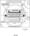
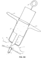
- FIG. 1 is an overview illustration of a sensor implantation method.
- the depicted method relates to implantation of an lOP sensor device 10 within an eye 1 of a patient by injecting the TOP sensor device 10 into the eye with a fluid-filled syringe 20 or injector.
- the IOP sensor device is positioned within the vitreous body of the eye 1 by penetrating the conjunctiva and sclera with a distal tip of a needle of a syringe 20 along insertion axis I extending through the ora serreta region.
- Implanting the sensor device by injection at this location is advantageous over conventional implantation methods as it avoids the potential for damaging the delicate structures within the anterior chambers and as well as damage to the photo-sensitive tissues of the retina.
- the injectable sensor can be implanted in a physician's office without surgery, such as by a relatively simple injection procedure using a standard needle size (e.g. 19 gauge). Once implanted the sensor device can provide continuous monitoring, up to one week or several weeks between charges.
- the system may include an external patient data acquisition unit that is used to charge the implanted sensor, collect and store data from the implanted sensor, and transmit the collected IOP data to a data server for further analysis and monitoring (e.g. the cloud or other server). The data may be available to the patient and/or the patient's treating physician at any time.
- the external patient data acquisition unit may be incorporated into a personal mobile device, such as a smart-phone.
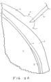
- FIGS. 2A-2D illustrate sequential steps of a method of implanting an IOP sensor within a vitreous body of an eye 1 in accordance with the approach described above in FIG. 1 .
- a fluid is injected into the conjunctiva 3 in the ora serrata region of the eyeball to form a ballooned portion 4 of the conjunctiva.
- the fluid may be saline and/or may include a numbing or anesthetic to reduce sensitivity in the eye 1 prior to penetrating the layers of the eye during implantation.
- the conjunctiva is the mucous membrane that lines the inner surface of the cyclids and is continued over the forepart of the eyeball.
- the ballooned portion facilitates deployment of the sensor device against the sclera and allows the conjunctiva to cover the proximal anchoring portion of the sensor device after implantation. as will be described in further detail below.
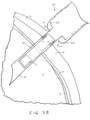
- a distal tip 21 of the fluid-filled syringe or injector 20 is penetrated through the ballooned portion 4 of the conjunctiva and through the sclera 5 and the choroid 6 until the distal tip 21 is positioned within the vitreous body 7.
- the sclera 5 is the dense fibrous opaque white outer coat enclosing the eyeball except the part covered by the cornea (not shown), while the choroid 6 is the vascular layer extending between the retina 8 and the sclera 5 to the ciliary body and iris (not shown) of the eye 1.
- the IOP sensor 10 is disposed within the distal tip 21 of the fluid-filled syringe and may include one or more anchoring members 12 constrained within the distal tip to be deployed upon release (e.g., self-expanding).
- the distal tip 21 is advanced distally along the insertion axis until a distal facing surface of the syringe 22 abuts against the ballooned portion 4.
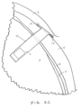
- the distal tip 21 is then retracted into the syringe 20 such that displacement of fluid within the syringe causes the sensor device 10 to maintain its position while the distal tip 21 is retracted, thereby releasing the sensor device from the syringe or injector 20.
- the anchoring members 12 resiliently extend laterally outward from the insertion axis against the outer surface of the sclera 5.
- This anchoring configuration substantially maintains the position of the sensor diaphragm s of the device 10 at the desired location so that an IOP sensor near a distal end of the sensor device remains entirely within the vitreous body. such as shown in FIGS. 2B and 2C .
- the anchoring members 12 prevent the sensor device 10 from potentially slipping into the vitreous body, which could cause damage to the retina or optic nerve 9.
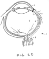
- FIG. 2D shows the sensor device 10 implanted within the eye.
- the sensor device 10 is configured such that a particular alignment (e.g. rotational) is not required to facilitate charging and/or wireless communication with the device.
- a particular alignment e.g. rotational
- the charging and communication coils are in close enough proximity such that an external device positioned near the eye can establish sufficient magnetic coupling so as to charge and/or communicate with the device.
- the orientation of the can be controlled by providing the sensor device in a substantially fixed or at least a known orientation within the distal tip such that controlling the orientation of the syringe or injector during implantation controls orientation of the sensor 10.
- the syringe can be marked (e.g. a line or arrow) so that the physician can visually align the syringe in a desired location to control orientation of the implanted sensor device 10.
- FIGS. 3A-3C illustrate an example sensor device 10 having two anchoring members at a proximal end thereof, which have a bias in a lateral direction.
- the anchoring members 12 extend laterally outward from an insertion axis i along which the sensor 10 is implanted.
- the anchoring members are shown as extending substantially perpendicular to the insertion axis, it is appreciated that the anchoring members could configured to extend along other angles (e.g. 30, 45 or 60 degrees from the insertion axis) according to a desired anchoring configuration or as needed for a particular application.
- the sensor device is formed, at least in part, using wafer processing methods, such that the anchoring members may be defined as features of a wafer or substrate of the sensor device.
- the sensor device may be formed on a silicon substrate and the anchoring members may be defined as features of the silicon substrate using wafer processing methods, such as deep etching.
- wafer processing methods such as deep etching.
- various wafer fabrication methods may be used to round or soften any sharp comers of the sensor device to avoid damage to eye tissues after implantation.
- the sensor device is formed, at least in part, on a rigid substrate, such as a silicon wafer.
- a rigid substrate such as a silicon wafer.
- portions of the substrate such as those portions defining the one or more anchoring members, may be processed so as to alter a mechanical property as desired.
- a wafer processing method may be used to define the anchoring members with a desired thickness and/or width so that the anchoring members become semi-rigid or flexible. This allows the one or more anchoring members to be sufficiently flexible in a direction in-plane with the device so as to bend alongside the sensor device when constrained within a distal tip of a needle, such as shown in FIG. 3B .
- the sensor device is sufficiently small enough to be injected through a needle (e.g.
- the anchoring members 12 resiliently return to their laterally extended configuration, as shown in FIG. 3C , so that when pushed distally along the insertion axis, the anchoring members engage an outer surface of the sclera. thereby preventing further distal movement of the sensor device.
- the conjunctiva covers and heals over the proximal surface of the sensor device such that the conjunctiva inhibits movement of the implanted sensor device in the proximal direction while the anchoring members inhibit movement of the implanted sensor in the distal direction.
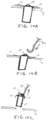
- FIG. 4A illustrates a detail view of a sensor device 10 having two resiliently deflectable anchoring members 12 at a proximal end of the device 10. which are constrained within the distal tip 21 of the syringe or injector.
- FIG. 4B illustrates a cross-sectional view of the sensor device of FIG. 4A constrained within the distal tip 21 of the syringe.
- the sensor device 10 comprises a vertically-stacked device formed, at least in part using wafer fabrication methods.
- the anchoring members 12 may be formed from a portion of a rigid substrate, such as a silicon wafer. Typically, the anchor is defined its own substrate material separate from the MEMS pressure sensor wafer.
- a MEMs device is supported on a rigid substrate that defines at least a part of the sensor. Forming the sensor on a rigid substrate may improve the integrity, accuracy and longevity of the MEMs device. while defining various other portions of the rigid substrate to be flexible allows for improved anchoring and/or deployment as needed for a given application. While a certain configuration of sensor, in particular a sensor having a vertically stacked architecture, it is appreciated that various other configurations may be utilized in accordance with the implantation methods described herein.
- the device may include a vertically stacked architecture such as those shown in FIG. 5 of U.S. Non-Provisional Patent Application Serial No. (Attorney Docket No. 96933-000210US) entitled "Hermetically Sealed Implant Sensors with Vertical Stacking Architecture.” filed concurrently herewith.
- the anchoring members are defined in a portion of the wafer that is thinned down (e.g. thinned to a 100 ⁇ m range) and that passes all electrical connections using TSV (through silicon vias).
- the electrical connections are scaled from the body fluid/media using a seal ring similar to the one used between MEMS wafer and CMOS wafer.
- the portion extending through the die area that will define the anchoring members will extend and typically etched using a process called DRIE to create the desired shape. This process may be done when all the wafers are bonded together so as to process them in a batch mode.
- the anchoring members are formed such that they are extended when the wafers are stacked, which creates a fairly wide spacing between each die.
- all edges are rounded with a wet etch (isotropic) to create soft corners and avoid sharp edges that may need to be eliminated to reducing tissue damage.
- the anchors are typically pre-etched (DRIE) and formed before the interposer is bonded. After the stack (CSP) is created via bonding, the dicing will cingulated each die but they will be left on blue-tape for pick and place. Each die with extended anchoring members is pushed into the syringe such that the anchoring members fold against the sidewall of the syringe. The angle and length of the anchoring members determines how much anchoring force the anchoring members provide against the tissue.
- the anchoring members are formed to provide an anchoring force within a range of 100 to 1,000 ⁇ N. It is appreciated that while such configurations are particularly useful for anchoring of the described sensor device 10 within the eye, various other configurations of anchoring members may be utilized, including anchoring members with sharpened edges (e.g. barbs), so as to facilitate anchoring within various other tissues. Such configuration may be particularly useful in sensor devices implanted in various other locations within the human body.
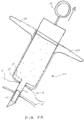
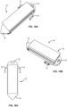
- FIGS. 5A-5B depict a syringe 20 or injector used in accordance with the sensor implantation methods described above.
- the syringe 20 may include an outer cylinder having a distal facing surface 22 and an inner cylinder 23 slidably disposed within.
- the syringe 20 may be provided to a surgeon pre-sterilized and pre-filled with a fluid and a sensor device fixed within the distal tip 21 of the syringe.
- the sensor device 10 may be releasably positioned within the distal tip 21 and may be held in place by force of the resilient anchoring members constrained within. After penetration of the sclera with the distal tip.
- the distal tip 21 as well as the inner cylinder attached thereto can be retracted, such as by pulling a proximal feature 25 (e.g. thumb ring) attached to the inner cylinder in a proximal direction while maintaining the outer cylinder position with the fingers against stabilizer 24.
- a proximal feature 25 e.g. thumb ring
- the fluid within the syringe is displaced, which moves the sensor device relative the distal tip during retraction so that the sensor device 10 substantially maintains its position and is released from the distal tip 21 as shown in FIG. 5B .
- the anchoring members 12 Upon release of the sensor device 10 from the distal tip 21, the anchoring members 12 deploy laterally outward thereby anchoring the sensor device against the sclera.
- the sensor device 10 may be pushed distally after deployment to facilitate engagement of the anchoring members 12 against the sclera and coverage of the anchoring members with the ballooned portion of the conjunctiva.
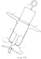
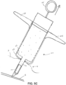
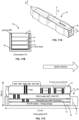
- FIGS. 5C-5D depict a syringe 20 or injector used in accordance with another implantation method, which is similar to that described above in FIGS. 5A-5B expect the needle or distal tip of die injector does not penetrate through the sclera. Rather, the distal tip is partly inserted into the sclera and the sensor device is advanced, in a similar manner as described above. such that a distal tip of the sensor device continues to advance through the sclera and into the vitreous body.
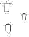
- FIGS. 6A-9A illustrate alternative example sensor devices having differing anchoring configuration and FIGS. 6B-9B illustrate each of the examples after implantation.
- the sensor device 10 may include anchoring members disposed on opposite sides of the sclera, such as shown in FIGS. 7A1. 7A2, 8A1, 8A2 and 9A , which may provide additional anchoring in both proximal and distal directions, as can be understood by referring to their deployed positions as shown in corresponding FIGS. 7B1, 7B2. 8B1, 8B2. and 9B , respectively.
- the sensor device 10 includes an extraction feature 13 that facilitates extraction of the sensor after implantation.
- the extraction feature 13 may include a hole or loop feature that interfaces with an extraction tool 30 to allow the sensor device 10 to be pulled in a proximal direction and extracted from the eye.
- the extraction feature 13 may include a separate feature attached to the device 10 or may be integrally formed with die device itself.
- the anchoring members are defined portions of a substrate or wafer of the sensor device
- the extraction 13 may be defined in a different portion of the same substrate or wafer.
- the anchoring members 12 are S-shaped portions of a rigid substrate, such as a silicon wafer
- the extraction feature 13 is a hole or opening formed within the same layer.
- the hole is dimensioned to allow an extraction tool 30, such as a hook-like tool, to be inserted within the hole to allow the implanted sensor device 10 to be proximally pulled and extracted from the eye.
- FIGS. 11-13 illustrate additional examples of sensor devices 10.
- FIG. 11 illustrates a sensor device 10 having two anchoring members 12 for engaging an outer surface of the sclera and two additional anchors 12' for engaging an inner surface of the sclera, as well as a proximal extraction feature.
- the anchoring members 12, 12' are dimensioned so that the anchoring members 12 that engage an outer surface of the sclera provide an anchoring force F1 that is greater than an anchoring force F2 provided by the anchoring members 1''' that engage an inner surface of the sclera.
- FIG. 12 illustrates a sensor device 10 having an S-shapcd anchoring member 12, which may be defined so as to provide a spring-like resistance when pushed against the sclera.
- FIG. 13 illustrates a sensor device 10 having anchoring members 12 and an extraction feature 13 at a proximal end of the device 10 and a penetrating tip 15 formed at the distal tip.
- anchoring members 12 and extraction feature 13 are each formed within a different portion of the same layer, such as a rigid substrate (e.g. a silicon wafer) of the device.
- a rigid substrate e.g. a silicon wafer
- Each of the features may be formed using wafer processing techniques such as deep plasma etching.
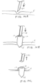
- An example of how such a penetrating tip 15 can be used is shown in the implantation method shown in FIGS. 14A-14C .
- the sensor device 10 can be implanted by injecting with a tool or device other than a fluid-filled syringe.
- the sclera is partly penetrated by a tool 50 leaving only a thin or weakened portion of the sclera.
- the sensor device is then advanced distally in this region until the penetrating tip 15 of the sensor device 10 penetrated through the sclera and into the vitreous body, as shown in FIG. 14B .
- the sensor device is advanced until the anchoring members 12 engage the sclera, as shown in FIG. 14C .
- the sensor device 10 may be advanced using a pusher tool 51 that interfaces with the extraction feature 13 such that the extraction feature facilitates implantation and extraction.
- the extraction/implantation feature 13 may be oblong in shape, such as a slot, so as to improve stability and prevent rotation or twisting of the sensor device when being pushed through the sclera with the pusher tool 51.
- this approach allows for a variety of alternative anchoring configurations since it docs not require that the anchoring members be constrained within a distal tip of a syringe.
- the anchoring members 12 could be relatively fixed in a laterally outward configuration, which may allow for thicker or more rigid anchoring members to be used if desired.
- FIGS. 15A-15D illustrate views of an alternative example sensor device 10 having a distal penetrating tip 15 for advancing through the sclera such as in the implantation method described above and an explantation feature 13 at the opposite end.
- This configuration does not include the anchoring members described above.
- Such an embodiment may be useful in an application where anchoring is not desired or needed, for example, when used with a shunt that is self-anchoring within the eye.
- FIGS. 16A-16C illustrate views of an example sensor device 10 formed with a vertically stacked architecture.
- a wafer or substrate extending through the device is defined to have a penetrating tip 15 for advancing through the sclera defined at the distal end of a wafer and an explanation feature 13 and anchoring members 12 defined in the same wafer at a proximal end of the device 10.
- the vertically stacked architecture of this device may be the same as that shown in FIG. 5 of U.S. Non-Provisional Patent Application Serial No. (Attorney Docket No. 96933-000210US) entitled "Hermetically Sealed Implant Sensors with Vertical Stacking Architecture.”
- FIGS. 17A-17C illustrate various view of an alternative design of a sensor device.
- the distal penetrating tip of the sensor device and the anchoring features arc integral parts of a support structure or boat in which the wafer-stacked sensor device resides and is bonded thereto. While the distal penetrating tip and/or the anchoring features arc described herein as being parts of an interposer layer or a boat support structure, it is appreciated that these components maybe configured in various other ways, including separately formed structures that are bonded to the sensor device after fabrication.
Landscapes
- Health & Medical Sciences (AREA)
- Life Sciences & Earth Sciences (AREA)
- Surgery (AREA)
- Medical Informatics (AREA)
- Animal Behavior & Ethology (AREA)
- Engineering & Computer Science (AREA)
- Biomedical Technology (AREA)
- Heart & Thoracic Surgery (AREA)
- Veterinary Medicine (AREA)
- Molecular Biology (AREA)
- Public Health (AREA)
- General Health & Medical Sciences (AREA)
- Pathology (AREA)
- Physics & Mathematics (AREA)
- Biophysics (AREA)
- Ophthalmology & Optometry (AREA)
- Nuclear Medicine, Radiotherapy & Molecular Imaging (AREA)
- Hematology (AREA)
- Infusion, Injection, And Reservoir Apparatuses (AREA)
Applications Claiming Priority (2)
| Application Number | Priority Date | Filing Date | Title |
|---|---|---|---|
| US201462019826P | 2014-07-01 | 2014-07-01 | |
| PCT/US2015/038862 WO2016004223A1 (en) | 2014-07-01 | 2015-07-01 | Methods and devices for implantation of intraocular pressure sensors |
Publications (3)
| Publication Number | Publication Date |
|---|---|
| EP3164061A1 EP3164061A1 (en) | 2017-05-10 |
| EP3164061A4 EP3164061A4 (en) | 2018-01-10 |
| EP3164061B1 true EP3164061B1 (en) | 2024-09-18 |
Family
ID=55016133
Family Applications (1)
| Application Number | Title | Priority Date | Filing Date |
|---|---|---|---|
| EP15815057.3A Active EP3164061B1 (en) | 2014-07-01 | 2015-07-01 | Methods and devices for implantation of intraocular pressure sensors |
Country Status (5)
| Country | Link |
|---|---|
| US (3) | US10213107B2 (enExample) |
| EP (1) | EP3164061B1 (enExample) |
| JP (1) | JP2017520327A (enExample) |
| CN (1) | CN106714665A (enExample) |
| WO (1) | WO2016004223A1 (enExample) |
Families Citing this family (26)
| Publication number | Priority date | Publication date | Assignee | Title |
|---|---|---|---|---|
| US20170360609A9 (en) | 2007-09-24 | 2017-12-21 | Ivantis, Inc. | Methods and devices for increasing aqueous humor outflow |
| EP2755549A1 (en) | 2011-09-13 | 2014-07-23 | Dose Medical Corporation | Intraocular physiological sensor |
| US9730638B2 (en) | 2013-03-13 | 2017-08-15 | Glaukos Corporation | Intraocular physiological sensor |
| JP2017527329A (ja) | 2014-07-01 | 2017-09-21 | インジェクトセンス, インコーポレイテッド | 垂直積層構造を備える、気密封止したインプラントセンサ |
| WO2016011056A1 (en) | 2014-07-14 | 2016-01-21 | Ivantis, Inc. | Ocular implant delivery system and method |
| CN108135470B (zh) | 2015-08-14 | 2021-03-09 | 伊万提斯公司 | 具有压力传感器和输送系统的眼部植入物 |
| US11938058B2 (en) | 2015-12-15 | 2024-03-26 | Alcon Inc. | Ocular implant and delivery system |
| US11497399B2 (en) | 2016-05-31 | 2022-11-15 | Qura, Inc. | Implantable intraocular pressure sensors and methods of use |
| WO2018231485A1 (en) * | 2017-06-13 | 2018-12-20 | Innfocus, Inc. | Systems, methods, and apparatus for treatment of glaucoma |
| EP3724650A4 (en) * | 2017-12-11 | 2021-09-08 | Microoptx Inc. | DEVICES AND METHODS FOR AN IMPLANTABLE OCULAR GLUCOSE SENSOR |
| EP4371535A3 (en) | 2018-02-22 | 2024-08-14 | Alcon Inc. | Ocular implant |
| DE102018203358A1 (de) * | 2018-03-07 | 2019-09-12 | Carl Zeiss Meditec Ag | Planungseinrichtung und -verfahren zur Erzeugung von Steuerdaten für ein ophthalmologisches Lasertherapiegerät für eine Zugangsstruktur |
| DE102018203424A1 (de) * | 2018-03-07 | 2019-09-12 | Carl Zeiss Meditec Ag | Shunt-Implantat |
| CN118542771A (zh) * | 2018-04-16 | 2024-08-27 | 温州医科大学 | 一种眼表植入物注射装置 |
| US11134984B2 (en) * | 2018-07-31 | 2021-10-05 | Medtronic, Inc. | Pressure-sensing implant tools |
| CN109528318A (zh) * | 2018-12-19 | 2019-03-29 | 四川大学华西医院 | 一种消化道早期癌症的术中定位装置 |
| WO2021003434A1 (en) * | 2019-07-03 | 2021-01-07 | Injectense, Inc. | Hermetic heterogeneous integration platform for active and passive electronic components |
| CA3165103A1 (en) * | 2019-12-17 | 2021-06-24 | Glaukos Corporation | Ocular tissue perforation device |
| US12419517B2 (en) * | 2020-08-21 | 2025-09-23 | Samsung Electronics Co., Ltd. | Nanophotonic sensor implants with 3D hybrid periodic-amorphous photonic crystals for wide-angle monitoring of long-term in-vivo intraocular pressure field |
| KR20230130622A (ko) | 2021-01-11 | 2023-09-12 | 알콘 인코포레이티드 | 점탄성 전달을 위한 시스템 및 방법 |
| EP4463086A4 (en) | 2022-01-12 | 2025-12-10 | Innovative Drive Corp | MECHANICAL HOLE PUNCH FOR REDUCING INTRAOCULAR PRESSURE AND METHODS OF USE |
| CN115054201A (zh) * | 2022-06-21 | 2022-09-16 | 山东大学 | 一种原位在线监测眼压的装置及工作方法 |
| KR102821957B1 (ko) * | 2022-09-13 | 2025-06-24 | 서울대학교병원 | 녹내장 치료용 방수유출기구를 안구에 삽입하는 방수유출기구 삽입장치 |
| US20250134712A1 (en) * | 2023-10-30 | 2025-05-01 | Avisi Technologies, Inc. | Thin-film ocular implant and delivery tool in open or minimally invasive surgical sites |
| US20250195207A1 (en) * | 2023-12-14 | 2025-06-19 | Verily Life Sciences Llc | System for attaching intraocular devices to iris tissue |
| CN120226988A (zh) * | 2025-04-23 | 2025-07-01 | 明澈生物科技(苏州)有限公司 | 一种眼压传感器 |
Family Cites Families (103)
| Publication number | Priority date | Publication date | Assignee | Title |
|---|---|---|---|---|
| US5178635A (en) * | 1992-05-04 | 1993-01-12 | Allergan, Inc. | Method for determining amount of medication in an implantable device |
| US5466233A (en) * | 1994-04-25 | 1995-11-14 | Escalon Ophthalmics, Inc. | Tack for intraocular drug delivery and method for inserting and removing same |
| IL109499A (en) | 1994-05-02 | 1998-01-04 | Univ Ramot | Implant device for draining excess intraocular fluid |
| US5666006A (en) | 1994-05-12 | 1997-09-09 | Apple Computer, Inc. | Circuit offering sequential discharge and simultaneous charge for a multiple battery system and method for charging multiple batteries |
| AU5857396A (en) * | 1995-05-14 | 1996-11-29 | Optonol Ltd. | Intraocular implant, delivery device, and method of implanta tion |
| IL113723A (en) * | 1995-05-14 | 2002-11-10 | Optonol Ltd | Intraocular implant |
| US5968058A (en) * | 1996-03-27 | 1999-10-19 | Optonol Ltd. | Device for and method of implanting an intraocular implant |
| GB9700390D0 (en) | 1997-01-10 | 1997-02-26 | Biocompatibles Ltd | Device for use in the eye |
| US6936053B1 (en) | 1998-07-02 | 2005-08-30 | Jeffrey N. Weiss | Ocular implant needle |
| US6346742B1 (en) | 1998-11-12 | 2002-02-12 | Maxim Integrated Products, Inc. | Chip-scale packaged pressure sensor |
| US6193656B1 (en) | 1999-02-08 | 2001-02-27 | Robert E. Jeffries | Intraocular pressure monitoring/measuring apparatus and method |
| RU2234894C2 (ru) | 1999-04-26 | 2004-08-27 | Джи-Эм-Пи Вижн Солюшнз, Инк. | Расширительное устройство и способ лечения глаукомы |
| AUPQ496500A0 (en) | 2000-01-06 | 2000-02-03 | University Of Sydney, The | Kit |
| US20050119737A1 (en) | 2000-01-12 | 2005-06-02 | Bene Eric A. | Ocular implant and methods for making and using same |
| US6638239B1 (en) | 2000-04-14 | 2003-10-28 | Glaukos Corporation | Apparatus and method for treating glaucoma |
| US20030060752A1 (en) | 2000-04-14 | 2003-03-27 | Olav Bergheim | Glaucoma device and methods thereof |
| US7708711B2 (en) | 2000-04-14 | 2010-05-04 | Glaukos Corporation | Ocular implant with therapeutic agents and methods thereof |
| US7867186B2 (en) | 2002-04-08 | 2011-01-11 | Glaukos Corporation | Devices and methods for treatment of ocular disorders |
| US6926670B2 (en) | 2001-01-22 | 2005-08-09 | Integrated Sensing Systems, Inc. | Wireless MEMS capacitive sensor for physiologic parameter measurement |
| CA2442652C (en) | 2001-04-07 | 2011-01-04 | Glaukos Corporation | Glaucoma stent and methods thereof for glaucoma treatment |
| US6666841B2 (en) | 2001-05-02 | 2003-12-23 | Glaukos Corporation | Bifurcatable trabecular shunt for glaucoma treatment |
| US7488303B1 (en) | 2002-09-21 | 2009-02-10 | Glaukos Corporation | Ocular implant with anchor and multiple openings |
| US6981958B1 (en) | 2001-05-02 | 2006-01-03 | Glaukos Corporation | Implant with pressure sensor for glaucoma treatment |
| US7431710B2 (en) | 2002-04-08 | 2008-10-07 | Glaukos Corporation | Ocular implants with anchors and methods thereof |
| US7678065B2 (en) | 2001-05-02 | 2010-03-16 | Glaukos Corporation | Implant with intraocular pressure sensor for glaucoma treatment |
| AU2002305400A1 (en) | 2001-05-03 | 2002-11-18 | Glaukos Corporation | Medical device and methods of use for glaucoma treatment |
| US20030078487A1 (en) | 2001-08-09 | 2003-04-24 | Jeffries Robert E. | Ocular pressure measuring device |
| US7331984B2 (en) * | 2001-08-28 | 2008-02-19 | Glaukos Corporation | Glaucoma stent for treating glaucoma and methods of use |
| US7163543B2 (en) | 2001-11-08 | 2007-01-16 | Glaukos Corporation | Combined treatment for cataract and glaucoma treatment |
| US20040116524A1 (en) | 2002-02-04 | 2004-06-17 | Cohen Ben Z. | Method of administering opthalmic fluids |
| US7186232B1 (en) | 2002-03-07 | 2007-03-06 | Glaukoa Corporation | Fluid infusion methods for glaucoma treatment |
| US7951155B2 (en) | 2002-03-15 | 2011-05-31 | Glaukos Corporation | Combined treatment for cataract and glaucoma treatment |
| US9301875B2 (en) | 2002-04-08 | 2016-04-05 | Glaukos Corporation | Ocular disorder treatment implants with multiple opening |
| US6890300B2 (en) * | 2002-08-27 | 2005-05-10 | Board Of Trustees Of Michigan State University | Implantable microscale pressure sensor system for pressure monitoring and management |
| US6899717B2 (en) * | 2002-09-18 | 2005-05-31 | Allergan, Inc. | Methods and apparatus for delivery of ocular implants |
| US7149587B2 (en) | 2002-09-26 | 2006-12-12 | Pacesetter, Inc. | Cardiovascular anchoring device and method of deploying same |
| US8303511B2 (en) * | 2002-09-26 | 2012-11-06 | Pacesetter, Inc. | Implantable pressure transducer system optimized for reduced thrombosis effect |
| JP3916549B2 (ja) | 2002-10-31 | 2007-05-16 | 東京エレクトロン株式会社 | プロセスモニタ及び半導体製造装置 |
| US6940111B2 (en) | 2002-11-29 | 2005-09-06 | Infineon Technologies Aktiengesellschaft | Radiation protection in integrated circuits |
| AU2004237774B2 (en) * | 2003-05-02 | 2009-09-10 | Surmodics, Inc. | Implantable controlled release bioactive agent delivery device |
| US8246974B2 (en) * | 2003-05-02 | 2012-08-21 | Surmodics, Inc. | Medical devices and methods for producing the same |
| US6979872B2 (en) | 2003-05-13 | 2005-12-27 | Rockwell Scientific Licensing, Llc | Modules integrating MEMS devices with pre-processed electronic circuitry, and methods for fabricating such modules |
| US8246569B1 (en) | 2004-08-17 | 2012-08-21 | California Institute Of Technology | Implantable intraocular pressure drain |
| US20060106434A1 (en) | 2004-11-12 | 2006-05-18 | Padgitt Steven T | Portable time harmonic tissue stimulator and method |
| US7306621B1 (en) | 2004-11-19 | 2007-12-11 | National Semiconductor Corporation | Heat transfer control for a prosthetic retinal device |
| US8118748B2 (en) | 2005-04-28 | 2012-02-21 | Medtronic, Inc. | Implantable capacitive pressure sensor system and method |
| US7562573B2 (en) | 2005-07-21 | 2009-07-21 | Evigia Systems, Inc. | Integrated sensor and circuitry and process therefor |
| CA2621993A1 (en) | 2005-09-16 | 2007-03-29 | Bg Implant, Inc. | Glaucoma treatment devices and methods |
| US9523657B2 (en) | 2006-02-14 | 2016-12-20 | Excellims Corporation | Practical ion mobility spectrometer apparatus and methods for chemical and/or biological detection |
| US20080097335A1 (en) * | 2006-08-04 | 2008-04-24 | Allergan, Inc. | Ocular implant delivery assemblies |
| EP2056708B1 (en) | 2006-08-29 | 2014-07-16 | California Institute of Technology | Microfabricated implantable wireless pressure sensor for use in biomedical applications and pressure measurement and sensor implantation methods |
| US20080057106A1 (en) | 2006-08-29 | 2008-03-06 | Erickson Signe R | Low profile bioactive agent delivery device |
| AU2007319383A1 (en) | 2006-11-10 | 2008-05-22 | Glaukos Corporation | Uveoscleral shunt and methods for implanting same |
| US8322346B2 (en) | 2007-06-28 | 2012-12-04 | Integrated Sensing Systems, Inc. | Minimally-invasive procedure for monitoring a physiological parameter within an internal organ |
| US8475374B2 (en) | 2007-08-23 | 2013-07-02 | Purdue Research Foundation | Intra-occular pressure sensor |
| FR2924913B1 (fr) | 2007-12-18 | 2010-02-05 | Alain Telandro | Systeme de mesure de la pression oculaire |
| EP2257250A2 (en) | 2008-01-29 | 2010-12-08 | Gilbert H. Kliman | Drug delivery devices, kits and methods therefor |
| US20100152646A1 (en) | 2008-02-29 | 2010-06-17 | Reshma Girijavallabhan | Intravitreal injection device and method |
| WO2009129450A2 (en) * | 2008-04-17 | 2009-10-22 | Yale University | Method for implanting intraocular pressure sensor |
| US20100016704A1 (en) | 2008-07-16 | 2010-01-21 | Naber John F | Method and system for monitoring a condition of an eye |
| WO2010056359A1 (en) | 2008-11-14 | 2010-05-20 | Optoelectronic Systems Consulting, Inc. | Miniaturized implantable sensor platform having multiple devices and sub-chips |
| US9636255B2 (en) | 2009-02-13 | 2017-05-02 | Dose Medical Corporation | Uveoscleral drug delivery implant and methods for implanting the same |
| US7819014B1 (en) | 2009-04-23 | 2010-10-26 | Rosemount Inc. | Capacitive gage pressure sensor with vacuum dielectric |
| US8182435B2 (en) | 2009-05-04 | 2012-05-22 | Alcon Research, Ltd. | Intraocular pressure sensor |
| JP5937004B2 (ja) | 2009-05-18 | 2016-06-22 | ドーズ メディカル コーポレーションDose Medical Corporation | 薬剤溶出眼内インプラント |
| US10206813B2 (en) | 2009-05-18 | 2019-02-19 | Dose Medical Corporation | Implants with controlled drug delivery features and methods of using same |
| WO2010149762A2 (en) | 2009-06-25 | 2010-12-29 | Imec | Biocompatible packaging |
| WO2011035228A1 (en) | 2009-09-18 | 2011-03-24 | Orthomems, Inc. | Implantable mems intraocular pressure sensor devices and methods for glaucoma monitoring |
| CN102711594A (zh) | 2009-09-18 | 2012-10-03 | 奥尔托梅姆斯有限公司 | 可植入的眼科微机电系统传感装置及眼睛外科手术方法 |
| US20130046166A1 (en) | 2010-04-06 | 2013-02-21 | Purdue Research Foundation | Intraocular pressure monitoring system |
| WO2011153538A2 (en) | 2010-06-04 | 2011-12-08 | The Regents Of The University Of Michigan | Implantable device and surgical implantation technique |
| US8569851B2 (en) | 2010-06-18 | 2013-10-29 | General Electric Company | Sensor and method for fabricating the same |
| US20120004528A1 (en) | 2010-07-02 | 2012-01-05 | Alcon Research, Ltd. | Implantable Remote Monitoring Sensor |
| HUE057267T2 (hu) * | 2010-08-05 | 2022-05-28 | Forsight Vision4 Inc | Berendezés szem kezelésére |
| GB201017637D0 (en) | 2010-10-20 | 2010-12-01 | Univ Dundee | Device for monitoring intraocular pressure |
| US8424388B2 (en) | 2011-01-28 | 2013-04-23 | Medtronic, Inc. | Implantable capacitive pressure sensor apparatus and methods regarding same |
| US8593273B2 (en) | 2011-02-07 | 2013-11-26 | Infineon Technologies Ag | Systems and methods for localization of tire pressure monitoring system wheel modules |
| CA2830949A1 (en) | 2011-04-07 | 2012-10-11 | Sensimed Sa | Device and method for detecting ophtalmic and/or brain diseases |
| EP2517619B1 (en) | 2011-04-27 | 2013-05-22 | Istar Medical | Improvements in or relating to glaucoma management and treatment |
| US20130001550A1 (en) | 2011-06-29 | 2013-01-03 | Invensense, Inc. | Hermetically sealed mems device with a portion exposed to the environment with vertically integrated electronics |
| CN103733304B (zh) | 2011-06-29 | 2016-08-17 | 因文森斯公司 | 其中一部分暴露在环境下并且带有竖直集成电子器件的气密封mems设备 |
| US9402994B2 (en) | 2011-07-14 | 2016-08-02 | Cyberonics, Inc. | Powering of an implantable medical therapy delivery device using far field radiative powering at multiple frequencies |
| US8794075B2 (en) | 2011-08-11 | 2014-08-05 | Nxp, B.V. | Multilayered NONON membrane in a MEMS sensor |
| EP2755549A1 (en) * | 2011-09-13 | 2014-07-23 | Dose Medical Corporation | Intraocular physiological sensor |
| US9072588B2 (en) | 2011-10-03 | 2015-07-07 | Alcon Research, Ltd. | Selectable varied control valve systems for IOP control systems |
| US9596988B2 (en) | 2011-10-12 | 2017-03-21 | Purdue Research Foundation | Pressure sensors for small-scale applications and related methods |
| EP2790568B1 (en) | 2011-12-16 | 2022-10-26 | California Institute of Technology | Device and system for sensing intraocular pressure |
| CN103190983A (zh) | 2012-01-05 | 2013-07-10 | 首都医科大学 | 一种房水引流植入物 |
| WO2013148275A2 (en) | 2012-03-26 | 2013-10-03 | Glaukos Corporation | System and method for delivering multiple ocular implants |
| US9504603B2 (en) * | 2012-04-02 | 2016-11-29 | Ocuject, Llc | Intraocular delivery devices and methods therefor |
| US8984950B2 (en) | 2012-04-20 | 2015-03-24 | Rosemount Aerospace Inc. | Separation mode capacitors for sensors |
| US9111473B1 (en) | 2012-08-24 | 2015-08-18 | Google Inc. | Input system |
| US9398868B1 (en) | 2012-09-11 | 2016-07-26 | Verily Life Sciences Llc | Cancellation of a baseline current signal via current subtraction within a linear relaxation oscillator-based current-to-frequency converter circuit |
| US20140107459A1 (en) * | 2012-10-11 | 2014-04-17 | Alcon Research, Ltd. | Devices, systems, and methods for intraocular measurements |
| US9022968B2 (en) | 2013-01-08 | 2015-05-05 | University Of South Florida | Auto-regulation system for intraocular pressure |
| WO2014137840A1 (en) | 2013-03-07 | 2014-09-12 | The Board Of Trustees Of The Leland Stanford Junior University | Implantable micro-fluidic device for monitoring of intra-ocular pressure |
| US9730638B2 (en) * | 2013-03-13 | 2017-08-15 | Glaukos Corporation | Intraocular physiological sensor |
| US9266717B2 (en) | 2013-03-15 | 2016-02-23 | Versana Micro Inc | Monolithically integrated multi-sensor device on a semiconductor substrate and method therefor |
| DE102014212457A1 (de) * | 2014-06-27 | 2015-12-31 | Implandata Ophthalmic Products Gmbh | Implantat zur Bestimmung des Augeninnendrucks |
| EP3164060A4 (en) | 2014-07-01 | 2018-03-14 | Injectsense, Inc. | Ultra low power charging implant sensors with wireless interface for patient monitoring |
| JP2017527329A (ja) | 2014-07-01 | 2017-09-21 | インジェクトセンス, インコーポレイテッド | 垂直積層構造を備える、気密封止したインプラントセンサ |
| EP2991172B1 (en) | 2014-08-27 | 2021-01-13 | TE Connectivity Germany GmbH | Vehicular cable assembly |
| WO2016064867A2 (en) | 2014-10-20 | 2016-04-28 | The Regents Of The University Of California | Optical intraocular sensor and sensing method |
-
2015
- 2015-07-01 EP EP15815057.3A patent/EP3164061B1/en active Active
- 2015-07-01 CN CN201580035734.6A patent/CN106714665A/zh active Pending
- 2015-07-01 WO PCT/US2015/038862 patent/WO2016004223A1/en not_active Ceased
- 2015-07-01 JP JP2016576070A patent/JP2017520327A/ja active Pending
- 2015-07-01 US US14/789,491 patent/US10213107B2/en active Active
-
2019
- 2019-01-15 US US16/248,699 patent/US11202568B2/en active Active
-
2021
- 2021-12-14 US US17/550,160 patent/US20220211269A1/en not_active Abandoned
Also Published As
| Publication number | Publication date |
|---|---|
| EP3164061A1 (en) | 2017-05-10 |
| US20160000325A1 (en) | 2016-01-07 |
| JP2017520327A (ja) | 2017-07-27 |
| CN106714665A (zh) | 2017-05-24 |
| EP3164061A4 (en) | 2018-01-10 |
| US20190246901A1 (en) | 2019-08-15 |
| WO2016004223A1 (en) | 2016-01-07 |
| US20220211269A1 (en) | 2022-07-07 |
| US10213107B2 (en) | 2019-02-26 |
| US11202568B2 (en) | 2021-12-21 |
Similar Documents
| Publication | Publication Date | Title |
|---|---|---|
| EP3164061B1 (en) | Methods and devices for implantation of intraocular pressure sensors | |
| JP6946523B2 (ja) | 眼内生理センサ | |
| US20220330819A1 (en) | Intraocular physiological sensor | |
| Chitnis et al. | A minimally invasive implantable wireless pressure sensor for continuous IOP monitoring | |
| JP2017520327A5 (enExample) | ||
| CN111801045A (zh) | 眼内生理传感器 | |
| US20030078487A1 (en) | Ocular pressure measuring device | |
| WO2009129450A2 (en) | Method for implanting intraocular pressure sensor | |
| US20140107459A1 (en) | Devices, systems, and methods for intraocular measurements | |
| JP2017520337A (ja) | 患者を監視するための、無線インターフェイスを備える超低電力充電式植え込みセンサ | |
| JP2017527329A (ja) | 垂直積層構造を備える、気密封止したインプラントセンサ |
Legal Events
| Date | Code | Title | Description |
|---|---|---|---|
| STAA | Information on the status of an ep patent application or granted ep patent |
Free format text: STATUS: THE INTERNATIONAL PUBLICATION HAS BEEN MADE |
|
| PUAI | Public reference made under article 153(3) epc to a published international application that has entered the european phase |
Free format text: ORIGINAL CODE: 0009012 |
|
| STAA | Information on the status of an ep patent application or granted ep patent |
Free format text: STATUS: REQUEST FOR EXAMINATION WAS MADE |
|
| 17P | Request for examination filed |
Effective date: 20170123 |
|
| AK | Designated contracting states |
Kind code of ref document: A1 Designated state(s): AL AT BE BG CH CY CZ DE DK EE ES FI FR GB GR HR HU IE IS IT LI LT LU LV MC MK MT NL NO PL PT RO RS SE SI SK SM TR |
|
| AX | Request for extension of the european patent |
Extension state: BA ME |
|
| DAV | Request for validation of the european patent (deleted) | ||
| DAX | Request for extension of the european patent (deleted) | ||
| A4 | Supplementary search report drawn up and despatched |
Effective date: 20171213 |
|
| RIC1 | Information provided on ipc code assigned before grant |
Ipc: A61F 9/007 20060101ALI20171205BHEP Ipc: A61B 17/34 20060101ALI20171205BHEP Ipc: A61B 5/00 20060101ALI20171205BHEP Ipc: A61B 5/03 20060101ALI20171205BHEP Ipc: A61B 5/07 20060101ALI20171205BHEP Ipc: A61B 3/16 20060101AFI20171205BHEP Ipc: A61B 90/00 20160101ALI20171205BHEP |
|
| STAA | Information on the status of an ep patent application or granted ep patent |
Free format text: STATUS: EXAMINATION IS IN PROGRESS |
|
| 17Q | First examination report despatched |
Effective date: 20210125 |
|
| GRAP | Despatch of communication of intention to grant a patent |
Free format text: ORIGINAL CODE: EPIDOSNIGR1 |
|
| STAA | Information on the status of an ep patent application or granted ep patent |
Free format text: STATUS: GRANT OF PATENT IS INTENDED |
|
| INTG | Intention to grant announced |
Effective date: 20240423 |
|
| P01 | Opt-out of the competence of the unified patent court (upc) registered |
Free format text: CASE NUMBER: APP_35316/2024 Effective date: 20240612 |
|
| GRAS | Grant fee paid |
Free format text: ORIGINAL CODE: EPIDOSNIGR3 |
|
| GRAA | (expected) grant |
Free format text: ORIGINAL CODE: 0009210 |
|
| STAA | Information on the status of an ep patent application or granted ep patent |
Free format text: STATUS: THE PATENT HAS BEEN GRANTED |
|
| AK | Designated contracting states |
Kind code of ref document: B1 Designated state(s): AL AT BE BG CH CY CZ DE DK EE ES FI FR GB GR HR HU IE IS IT LI LT LU LV MC MK MT NL NO PL PT RO RS SE SI SK SM TR |
|
| REG | Reference to a national code |
Ref country code: GB Ref legal event code: FG4D |
|
| REG | Reference to a national code |
Ref country code: CH Ref legal event code: EP |
|
| REG | Reference to a national code |
Ref country code: DE Ref legal event code: R096 Ref document number: 602015089939 Country of ref document: DE |
|
| REG | Reference to a national code |
Ref country code: IE Ref legal event code: FG4D |
|
| REG | Reference to a national code |
Ref country code: LT Ref legal event code: MG9D |
|
| PG25 | Lapsed in a contracting state [announced via postgrant information from national office to epo] |
Ref country code: NO Free format text: LAPSE BECAUSE OF FAILURE TO SUBMIT A TRANSLATION OF THE DESCRIPTION OR TO PAY THE FEE WITHIN THE PRESCRIBED TIME-LIMIT Effective date: 20241218 |
|
| PG25 | Lapsed in a contracting state [announced via postgrant information from national office to epo] |
Ref country code: GR Free format text: LAPSE BECAUSE OF FAILURE TO SUBMIT A TRANSLATION OF THE DESCRIPTION OR TO PAY THE FEE WITHIN THE PRESCRIBED TIME-LIMIT Effective date: 20241219 Ref country code: FI Free format text: LAPSE BECAUSE OF FAILURE TO SUBMIT A TRANSLATION OF THE DESCRIPTION OR TO PAY THE FEE WITHIN THE PRESCRIBED TIME-LIMIT Effective date: 20240918 |
|
| PG25 | Lapsed in a contracting state [announced via postgrant information from national office to epo] |
Ref country code: BG Free format text: LAPSE BECAUSE OF FAILURE TO SUBMIT A TRANSLATION OF THE DESCRIPTION OR TO PAY THE FEE WITHIN THE PRESCRIBED TIME-LIMIT Effective date: 20240918 |
|
| PG25 | Lapsed in a contracting state [announced via postgrant information from national office to epo] |
Ref country code: LV Free format text: LAPSE BECAUSE OF FAILURE TO SUBMIT A TRANSLATION OF THE DESCRIPTION OR TO PAY THE FEE WITHIN THE PRESCRIBED TIME-LIMIT Effective date: 20240918 |
|
| PG25 | Lapsed in a contracting state [announced via postgrant information from national office to epo] |
Ref country code: HR Free format text: LAPSE BECAUSE OF FAILURE TO SUBMIT A TRANSLATION OF THE DESCRIPTION OR TO PAY THE FEE WITHIN THE PRESCRIBED TIME-LIMIT Effective date: 20240918 |
|
| REG | Reference to a national code |
Ref country code: NL Ref legal event code: MP Effective date: 20240918 |
|
| PG25 | Lapsed in a contracting state [announced via postgrant information from national office to epo] |
Ref country code: RS Free format text: LAPSE BECAUSE OF FAILURE TO SUBMIT A TRANSLATION OF THE DESCRIPTION OR TO PAY THE FEE WITHIN THE PRESCRIBED TIME-LIMIT Effective date: 20241218 |
|
| PG25 | Lapsed in a contracting state [announced via postgrant information from national office to epo] |
Ref country code: RS Free format text: LAPSE BECAUSE OF FAILURE TO SUBMIT A TRANSLATION OF THE DESCRIPTION OR TO PAY THE FEE WITHIN THE PRESCRIBED TIME-LIMIT Effective date: 20241218 Ref country code: NO Free format text: LAPSE BECAUSE OF FAILURE TO SUBMIT A TRANSLATION OF THE DESCRIPTION OR TO PAY THE FEE WITHIN THE PRESCRIBED TIME-LIMIT Effective date: 20241218 Ref country code: LV Free format text: LAPSE BECAUSE OF FAILURE TO SUBMIT A TRANSLATION OF THE DESCRIPTION OR TO PAY THE FEE WITHIN THE PRESCRIBED TIME-LIMIT Effective date: 20240918 Ref country code: HR Free format text: LAPSE BECAUSE OF FAILURE TO SUBMIT A TRANSLATION OF THE DESCRIPTION OR TO PAY THE FEE WITHIN THE PRESCRIBED TIME-LIMIT Effective date: 20240918 Ref country code: GR Free format text: LAPSE BECAUSE OF FAILURE TO SUBMIT A TRANSLATION OF THE DESCRIPTION OR TO PAY THE FEE WITHIN THE PRESCRIBED TIME-LIMIT Effective date: 20241219 Ref country code: FI Free format text: LAPSE BECAUSE OF FAILURE TO SUBMIT A TRANSLATION OF THE DESCRIPTION OR TO PAY THE FEE WITHIN THE PRESCRIBED TIME-LIMIT Effective date: 20240918 Ref country code: BG Free format text: LAPSE BECAUSE OF FAILURE TO SUBMIT A TRANSLATION OF THE DESCRIPTION OR TO PAY THE FEE WITHIN THE PRESCRIBED TIME-LIMIT Effective date: 20240918 |
|
| REG | Reference to a national code |
Ref country code: AT Ref legal event code: MK05 Ref document number: 1723992 Country of ref document: AT Kind code of ref document: T Effective date: 20240918 |
|
| PG25 | Lapsed in a contracting state [announced via postgrant information from national office to epo] |
Ref country code: NL Free format text: LAPSE BECAUSE OF FAILURE TO SUBMIT A TRANSLATION OF THE DESCRIPTION OR TO PAY THE FEE WITHIN THE PRESCRIBED TIME-LIMIT Effective date: 20240918 |
|
| PG25 | Lapsed in a contracting state [announced via postgrant information from national office to epo] |
Ref country code: PT Free format text: LAPSE BECAUSE OF FAILURE TO SUBMIT A TRANSLATION OF THE DESCRIPTION OR TO PAY THE FEE WITHIN THE PRESCRIBED TIME-LIMIT Effective date: 20250120 Ref country code: IS Free format text: LAPSE BECAUSE OF FAILURE TO SUBMIT A TRANSLATION OF THE DESCRIPTION OR TO PAY THE FEE WITHIN THE PRESCRIBED TIME-LIMIT Effective date: 20250118 |
|
| PG25 | Lapsed in a contracting state [announced via postgrant information from national office to epo] |
Ref country code: RO Free format text: LAPSE BECAUSE OF FAILURE TO SUBMIT A TRANSLATION OF THE DESCRIPTION OR TO PAY THE FEE WITHIN THE PRESCRIBED TIME-LIMIT Effective date: 20240918 Ref country code: SM Free format text: LAPSE BECAUSE OF FAILURE TO SUBMIT A TRANSLATION OF THE DESCRIPTION OR TO PAY THE FEE WITHIN THE PRESCRIBED TIME-LIMIT Effective date: 20240918 |
|
| PG25 | Lapsed in a contracting state [announced via postgrant information from national office to epo] |
Ref country code: ES Free format text: LAPSE BECAUSE OF FAILURE TO SUBMIT A TRANSLATION OF THE DESCRIPTION OR TO PAY THE FEE WITHIN THE PRESCRIBED TIME-LIMIT Effective date: 20240918 |
|
| PG25 | Lapsed in a contracting state [announced via postgrant information from national office to epo] |
Ref country code: EE Free format text: LAPSE BECAUSE OF FAILURE TO SUBMIT A TRANSLATION OF THE DESCRIPTION OR TO PAY THE FEE WITHIN THE PRESCRIBED TIME-LIMIT Effective date: 20240918 Ref country code: AT Free format text: LAPSE BECAUSE OF FAILURE TO SUBMIT A TRANSLATION OF THE DESCRIPTION OR TO PAY THE FEE WITHIN THE PRESCRIBED TIME-LIMIT Effective date: 20240918 |
|
| PG25 | Lapsed in a contracting state [announced via postgrant information from national office to epo] |
Ref country code: CZ Free format text: LAPSE BECAUSE OF FAILURE TO SUBMIT A TRANSLATION OF THE DESCRIPTION OR TO PAY THE FEE WITHIN THE PRESCRIBED TIME-LIMIT Effective date: 20240918 Ref country code: PL Free format text: LAPSE BECAUSE OF FAILURE TO SUBMIT A TRANSLATION OF THE DESCRIPTION OR TO PAY THE FEE WITHIN THE PRESCRIBED TIME-LIMIT Effective date: 20240918 |
|
| PG25 | Lapsed in a contracting state [announced via postgrant information from national office to epo] |
Ref country code: SK Free format text: LAPSE BECAUSE OF FAILURE TO SUBMIT A TRANSLATION OF THE DESCRIPTION OR TO PAY THE FEE WITHIN THE PRESCRIBED TIME-LIMIT Effective date: 20240918 Ref country code: IT Free format text: LAPSE BECAUSE OF FAILURE TO SUBMIT A TRANSLATION OF THE DESCRIPTION OR TO PAY THE FEE WITHIN THE PRESCRIBED TIME-LIMIT Effective date: 20240918 |
|
| REG | Reference to a national code |
Ref country code: DE Ref legal event code: R097 Ref document number: 602015089939 Country of ref document: DE |
|
| PG25 | Lapsed in a contracting state [announced via postgrant information from national office to epo] |
Ref country code: DK Free format text: LAPSE BECAUSE OF FAILURE TO SUBMIT A TRANSLATION OF THE DESCRIPTION OR TO PAY THE FEE WITHIN THE PRESCRIBED TIME-LIMIT Effective date: 20240918 |
|
| PLBE | No opposition filed within time limit |
Free format text: ORIGINAL CODE: 0009261 |
|
| STAA | Information on the status of an ep patent application or granted ep patent |
Free format text: STATUS: NO OPPOSITION FILED WITHIN TIME LIMIT |
|
| 26N | No opposition filed |
Effective date: 20250619 |
|
| PG25 | Lapsed in a contracting state [announced via postgrant information from national office to epo] |
Ref country code: SE Free format text: LAPSE BECAUSE OF FAILURE TO SUBMIT A TRANSLATION OF THE DESCRIPTION OR TO PAY THE FEE WITHIN THE PRESCRIBED TIME-LIMIT Effective date: 20240918 |
|
| PGFP | Annual fee paid to national office [announced via postgrant information from national office to epo] |
Ref country code: DE Payment date: 20250722 Year of fee payment: 11 |
|
| PGFP | Annual fee paid to national office [announced via postgrant information from national office to epo] |
Ref country code: GB Payment date: 20250728 Year of fee payment: 11 |
|
| PGFP | Annual fee paid to national office [announced via postgrant information from national office to epo] |
Ref country code: FR Payment date: 20250728 Year of fee payment: 11 |