EP3163134A1 - Élément coulissant - Google Patents
Élément coulissant Download PDFInfo
- Publication number
- EP3163134A1 EP3163134A1 EP15812456.0A EP15812456A EP3163134A1 EP 3163134 A1 EP3163134 A1 EP 3163134A1 EP 15812456 A EP15812456 A EP 15812456A EP 3163134 A1 EP3163134 A1 EP 3163134A1
- Authority
- EP
- European Patent Office
- Prior art keywords
- pressure fluid
- fluid side
- dimples
- positive pressure
- high pressure
- Prior art date
- Legal status (The legal status is an assumption and is not a legal conclusion. Google has not performed a legal analysis and makes no representation as to the accuracy of the status listed.)
- Granted
Links
- 239000012530 fluid Substances 0.000 claims abstract description 196
- 238000007789 sealing Methods 0.000 claims abstract description 117
- 230000015572 biosynthetic process Effects 0.000 claims abstract description 56
- 238000011144 upstream manufacturing Methods 0.000 claims abstract description 45
- 230000007246 mechanism Effects 0.000 claims description 31
- 238000005461 lubrication Methods 0.000 description 19
- 230000002265 prevention Effects 0.000 description 6
- 239000007788 liquid Substances 0.000 description 5
- 230000000694 effects Effects 0.000 description 4
- 230000002093 peripheral effect Effects 0.000 description 4
- 230000008901 benefit Effects 0.000 description 3
- 238000010008 shearing Methods 0.000 description 3
- 230000003247 decreasing effect Effects 0.000 description 2
- 238000005086 pumping Methods 0.000 description 2
- 238000007792 addition Methods 0.000 description 1
- 239000000470 constituent Substances 0.000 description 1
- 230000008094 contradictory effect Effects 0.000 description 1
- 230000007613 environmental effect Effects 0.000 description 1
- 230000006872 improvement Effects 0.000 description 1
- 230000001050 lubricating effect Effects 0.000 description 1
- 239000010687 lubricating oil Substances 0.000 description 1
- 239000000463 material Substances 0.000 description 1
- 238000012986 modification Methods 0.000 description 1
- 230000004048 modification Effects 0.000 description 1
Images


Classifications
-
- F—MECHANICAL ENGINEERING; LIGHTING; HEATING; WEAPONS; BLASTING
- F16—ENGINEERING ELEMENTS AND UNITS; GENERAL MEASURES FOR PRODUCING AND MAINTAINING EFFECTIVE FUNCTIONING OF MACHINES OR INSTALLATIONS; THERMAL INSULATION IN GENERAL
- F16J—PISTONS; CYLINDERS; SEALINGS
- F16J15/00—Sealings
- F16J15/16—Sealings between relatively-moving surfaces
- F16J15/34—Sealings between relatively-moving surfaces with slip-ring pressed against a more or less radial face on one member
- F16J15/3404—Sealings between relatively-moving surfaces with slip-ring pressed against a more or less radial face on one member and characterised by parts or details relating to lubrication, cooling or venting of the seal
- F16J15/3408—Sealings between relatively-moving surfaces with slip-ring pressed against a more or less radial face on one member and characterised by parts or details relating to lubrication, cooling or venting of the seal at least one ring having an uneven slipping surface
- F16J15/3412—Sealings between relatively-moving surfaces with slip-ring pressed against a more or less radial face on one member and characterised by parts or details relating to lubrication, cooling or venting of the seal at least one ring having an uneven slipping surface with cavities
-
- F—MECHANICAL ENGINEERING; LIGHTING; HEATING; WEAPONS; BLASTING
- F16—ENGINEERING ELEMENTS AND UNITS; GENERAL MEASURES FOR PRODUCING AND MAINTAINING EFFECTIVE FUNCTIONING OF MACHINES OR INSTALLATIONS; THERMAL INSULATION IN GENERAL
- F16J—PISTONS; CYLINDERS; SEALINGS
- F16J15/00—Sealings
- F16J15/16—Sealings between relatively-moving surfaces
- F16J15/164—Sealings between relatively-moving surfaces the sealing action depending on movements; pressure difference, temperature or presence of leaking fluid
Definitions
- the present invention relates to sliding parts suitable for a mechanical seal, a bearing, and other sliding portions for example.
- the present invention relates to sliding parts such as a sealing ring or a bearing in which a fluid lies on sealing faces to reduce friction and there is a need for preventing fluid leakage from the sealing faces.
- Patent Citation 1 discloses the invention in which a plurality of spiral grooves of moving a fluid to the high pressure chamber side is provided in circumferential direction on a seal face of a rotating ring (hereinafter, called as "Background Art 1. ”)
- the present invention relates to improvement of the invention described in Patent Citation 2, and an objective thereof is to provide sliding parts having, by smoothening movement of a fluid from a cavitation formation region on the upstream side to a positive pressure generation region on the downstream side in a dent part such as a dimple formed on a sealing face (called as the "dimple” in this description), both functions of furthermore leakage prevention and lubrication irrespective of the magnitude of a pressure difference between inner and outer peripheries of the sealing face.
- an objective of the present invention is to provide sliding parts in which the function of the leakage prevention is furthermore improved by increasing a negative pressure generation starting point and disposing the cavitation formation regions over substantially all the periphery on the low pressure fluid side.
- a first aspect of the sliding parts of the present invention is a pair of sliding parts in which a plurality of dimples is provided independently from each other in the circumferential direction on one of sealing faces that relatively slide on each other, characterized in that:
- the fluid to be leaked out to the low pressure fluid side from the positive pressure generation region of the dimple on the upstream side flows into the upstream side in the cavitation formation region of the dimple on the downstream side.
- leakage to the low pressure fluid side is inhibited and a sealing property is improved. That is, since the cavitation formation regions are disposed over substantially all the periphery on the low pressure fluid side, a function of leakage prevention can be furthermore improved.
- Radial width of the cavitation formation region can be increased.
- a negative pressure generation starting point can be increased and the sealing property can be improved.
- the fluid flowing into the cavitation formation region smoothly flows to the positive pressure generation region and positive pressure is not generated in a flow of the fluid collided with the low pressure fluid side edge.
- dynamic pressure generation on the leading end side in the positive pressure generation region on the low pressure fluid side can be suppressed, and an amount of the fluid leaked out to the low pressure fluid side can be reduced.
- a second aspect of the sliding parts of the present invention relates to the first aspect, characterized in that:
- a fluid film can be formed and lubrication can be made by the positive pressure generation mechanism formed from the Rayleigh step which is disposed on the high pressure fluid side, and sealing and the lubrication can be made by the dimples disposed on the low pressure fluid side.
- a sealing operation by the dimples can be ensured.
- a third aspect of the sliding parts of the present invention relates to the first aspect, characterized in that:
- a fluid film is formed and the lubrication is made by the positive pressure generation mechanism formed from the Rayleigh step which is disposed on the high pressure fluid side, and the sealing and the lubrication are made by the dimples disposed on the low pressure fluid side, and there is no need for providing deep grooves such as a radial groove and a pressure release groove.
- the present invention exhibits the following superior effects.
- the radial width of the cavitation formation region can be increased.
- the negative pressure generation starting point can be increased and the sealing property can be improved.
- the cavitation formation region is increased, the shearing resistance of the sealing face can be reduced, and the torque of the sliding parts can be lowered.
- the fluid flowing into the cavitation formation region smoothly flows to the positive pressure generation region and positive pressure is not generated in the flow of the fluid collided with the low pressure fluid side edge.
- the dynamic pressure generation on the leading end side in the positive pressure generation region on the low pressure fluid side can be suppressed, and the amount of the fluid leaked out to the low pressure fluid side can be reduced.
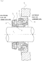
- FIG. 1 is a vertically sectional view illustrating one example of the mechanical seal that is an inside mechanical seal for sealing a sealed fluid on the high pressure fluid side to be leaked out from an outer periphery of a sealing face toward an inner periphery.
- an annular rotating ring 3 is provided via a sleeve 2 in a state that the rotating ring can be rotated integrally with this rotating shaft 1
- an annular stationary ring 5 is provided in a housing 4 of a pump in a state that the stationary ring is not rotated but can be moved in the axial direction
- sealing faces S mirror-finished by lapping or the like closely slide on each other by means of a coiled wave spring 6 and bellows 7 that bias this stationary ring 5 in the axial direction. That is, this mechanical seal is to prevent the sealed fluid from flowing out from an outer periphery of the rotating shaft 1 to the atmosphere side on the sealing faces
- the present invention is not limited to the inside mechanical seal but, needless to say, can be applied to an outside mechanical seal for sealing a sealed fluid on the high pressure fluid side to be leaked out from an inner periphery of a sealing face toward an outer periphery.
- FIG. 2 illustrates the sealing face of the sliding part according to the first embodiment of the present invention.
- a case where dimples are formed on the sliding face of the stationary ring 5 of FIG. 1 will be described as an example.
- a plurality of dimples 10 is provided in the circumferential direction on the sealing face S.
- the dimples 10 do not communicate with the high pressure fluid side and the low pressure fluid side.
- the dimples 10 are provided independently from each other and separated from each other in the circumferential direction.
- the number, an area, and depth of the dimples 10 are appropriately determined in accordance with a diameter of the sliding part, width and relative movement speed of the sealing face, conditions of sealing and lubricity, and the like. However, shallow dimples having a large area are more preferable in terms of a fluid lubrication operation and liquid film formation.
- the six dimples 10 are provided at equal intervals. However, four dimples or eight dimples may be provided at equal intervals.
- Each of the dimples 10 is formed along the circumferential direction with substantially fixed width so as to form an arc shape from a cavitation formation region 10a on the upstream side to a positive pressure generation region 10b on the downstream side.
- a low pressure fluid side edge 10c of the cavitation formation region 10a of the dimple 10 is isolated from the low pressure fluid side by the sealing face S1, and a high pressure fluid side edge 10d is similarly isolated from the high pressure fluid side by the sealing face S2.
- a fluid suctioned in the cavitation formation region 10a of the dimple 10 passes through an inside of the dimples and generates dynamic pressure (positive pressure) in the positive pressure generation region 10b, and is returned to the high pressure fluid side which is near in the radial direction.
- An upstream beginning end 10e of the cavitation formation region 10a is formed in a tapered shape inclined with respect to the rotating direction of the opposing sealing face from the low pressure fluid side toward the high pressure fluid side, and disposed so as to overlap the positive pressure generation region 10b of the dimple 10 arranged on the upstream side in the radial direction.
- a taper angle ⁇ 1 made by the upstream beginning end 10e and the low pressure fluid side edge 10c is set to for example 0° ⁇ ⁇ 1 ⁇ 45°.
- the upstream beginning end 10e on the upstream side is not limited to a straight line but may be a curve such as a single smooth arc shape.
- the upstream beginning end 10e of the cavitation formation region 10a is formed in a tapered shape inclined so as to be substantially parallel to a low pressure fluid side edge 10f of the positive pressure generation region 10b of the dimple 10 arranged on the upstream side, and disposed so as to overlap at least a part of a hatched substantially-triangle region P where the positive pressure is generated in the positive pressure generation region 10b of the dimple 10 arranged on the upstream side in the radial direction.
- the upstream beginning end 10e By forming the upstream beginning end 10e so as to make the beginning end substantially parallel to the low pressure fluid side edge 10f of the positive pressure generation region 10b of the dimple 10 arranged on the upstream side, arranging efficiency of the dimples on the sealing face S (proportion of the entire area of the dimples to the entire area of the sealing face) can be improved.
- the fluid shown by an arrow R to be leaked out to the low pressure fluid side from the positive pressure generation region 10b of the dimple 10 on the upstream side flows into the upstream side in the cavitation formation region 10a of the dimple 10 on the downstream side.
- leakage to the low pressure fluid side is inhibited and a sealing property is improved. That is, since the cavitation formation regions are disposed over substantially all the periphery on the low pressure fluid side, a function of leakage prevention can be furthermore improved.
- the radial width of the cavitation formation region can be increased.
- a negative pressure generation starting point can be increased and the sealing property can be improved.
- the low pressure fluid side edge 10f of the positive pressure generation region 10b is formed in a tapered shape inclined with respect to the rotating direction of the opposing sealing face from the low pressure fluid side toward the high pressure fluid side and smoothly connected to the low pressure fluid side edge 10c of the cavitation formation region 10a.
- a taper angle ⁇ 2 made by the low pressure fluid side edge 10f of the positive pressure generation region 10b and the low pressure fluid side edge 10c of the cavitation formation region 10a is set to for example 0° ⁇ ⁇ 2 ⁇ 45°.
- the low pressure fluid side edge 10f is not limited to a straight line but may be a projected or recessed curve toward the low pressure fluid side. In a case of a straight line, a single straight line is desirable. In a case of a curve, curvature is desirably uniform.
- the low pressure fluid side edge 10f of the positive pressure generation region 10b is formed in a tapered shape inclined with respect to the rotating direction of the opposing sealing face from the low pressure fluid side toward the high pressure fluid side and smoothly connected to the low pressure fluid side edge 10c of the cavitation formation region 10a.
- the fluid flowing into the cavitation formation region 10a smoothly flows to the positive pressure generation region 10b and the positive pressure is not generated in a flow of the fluid collided with the low pressure fluid side edge 10f. Therefore, in comparison to the sliding parts of Background Art 2 described above, dynamic pressure generation on the leading end side in the positive pressure generation region 10b on the low pressure fluid side can be suppressed, and an amount of the fluid leaked out to the low pressure fluid side can be reduced.
- a positive pressure generation portion where the positive pressure is generated in the positive pressure generation region 10b is the hatched substantially-triangle region P of FIG. 2 .
- a distance from a pressure peak position on the leading end side to the low pressure fluid side is increased.
- pressure gradient is decreased and a leakage amount can be reduced.
- the taper angle ⁇ 2 of the low pressure fluid side edge 10f of the positive pressure generation region 10b is desirably as small as possible from a viewpoint to let the fluid collided with the low pressure fluid side edge 10f smoothly flow and not to generate the positive pressure.
- a shape of the dimple 10 illustrated in FIG. 2 is only one example.
- the dimple is only required to be formed along the circumferential direction with substantially fixed width, and regarding to the cavitation formation region 10a, the beginning end 10e is only required to be formed in a tapered shape inclined with respect to the rotating direction of the opposing sealing face from the low pressure fluid side toward the high pressure fluid side, and disposed so as to overlap the positive pressure generation region 10b of the dimple 10 arranged on the upstream side in the radial direction.
- the taper angle, a degree of overlap with the positive pressure generation region 10b of the dimple 10 on the upstream side in the radial direction, and the like may be determined on the basis of design.
- the low pressure fluid side edge 10f of the positive pressure generation region 10b is only required to be formed in a tapered shape inclined with respect to the rotating direction of the opposing sealing face from the low pressure fluid side toward the high pressure fluid side and smoothly connected to the low pressure fluid side edge 10c of the cavitation formation region 10a.
- the low pressure fluid side edge may be formed in a shape like a side surface of a bow part of a ship.
- FIG. 3A as shown by an arrow, the rotating ring 3 is rotated and moved anti-clockwise with respect to the stationary ring 5.
- a narrowing gap (step) 11 exists on the downstream side in the dimple 10.
- the sealing face of the opposing rotating ring 3 is flat.
- FIG. 3B as shown by an arrow, the rotating ring 3 is rotated and moved anti-clockwise with respect to the stationary ring 5.
- an extending gap (step) 12 exists on the upstream side in the dimple 10.
- the sealing face of the opposing rotating ring 3 is flat.
- the negative pressure is generated on the upstream side in the dimple 10, and the positive pressure is generated on the downstream side.
- cavitation is generated in a negative pressure generation region on the upstream side.
- FIG. 4 illustrates a sealing face of a sliding part according to a second embodiment of the present invention.
- a case where dimples are formed on the sealing face of the stationary ring 5 of FIG. 1 will be described as an example.
- the second embodiment is different from the first embodiment illustrated in FIG. 2 in a point that positive pressure generation mechanisms formed from Rayleigh steps are disposed on the high pressure fluid side on the sealing face in which the dimples are provided.
- the other points are basically the same as the first embodiment.
- the same members will be given the same reference signs and duplicated description thereof will be omitted.
- dimples 10 are disposed on the low pressure fluid side and positive pressure generation mechanisms formed from Rayleigh steps 20 are disposed on the high pressure fluid side.
- Each of the Rayleigh steps 20 is formed from a narrowing step 21, a groove section 22, and a radial groove 23 communicating with the high pressure fluid side. Between the Rayleigh steps 20 and the dimples 10, a pressure release groove 24 communicating with the high pressure fluid side via the radial grooves 23 is provided.
- the groove section 22 is disposed so as to be isolated from the high pressure fluid side by a sealing face S3 with fixed width, extending in the circumferential direction with fixed width so as to form an arc shape. Depth of the groove sections 22 is several times more than the depth of the dimples 10.
- the pressure release groove 24 is to release the dynamic pressure (positive pressure) generated in the Rayleigh steps 20 to the pressure of the high pressure side fluid so as to prevent the fluid from flowing into the dimples 10 on the low pressure fluid side to weaken a negative pressure generation ability of the dimples 10.
- the pressure release groove is to play a role of guiding the fluid to flow into the low pressure fluid side by the positive pressure generated in the Rayleigh steps 20 on the high pressure fluid side to the pressure release groove 24, and letting the fluid go to the high pressure fluid side.
- the six dimples 10 are provided at equal intervals, and the eight Rayleigh steps 20 are provided at equal intervals.
- Depth and width of the groove sections 22, the radial grooves 23, and the pressure release groove 24 are appropriately determined in accordance with the diameter of the sliding part, the width and the relative movement speed of the sealing face, the conditions of the sealing and the lubricity, and the like.
- the depth of the groove sections 22 is about a half to several times more than the depth of the dimples 10.
- the depths of the radial grooves 23 and the pressure release groove 24 are ten times more than the depth of the dimples 10 or more.
- a fluid film is formed and the lubrication is made by the positive pressure generation mechanisms formed from the Rayleigh steps 20 which are disposed on the high pressure fluid side, and the sealing and the lubrication are made by the dimples 10 disposed on the low pressure fluid side.
- the fluid suctioned in the cavitation formation region 10a of the dimple 10 is guided from the positive pressure generation region 10b to the pressure release groove 24 and returned to the high pressure fluid side via the radial groove 23.
- the fluid film can be formed and the lubrication can be made by the positive pressure generation mechanisms formed from the Rayleigh steps 20 which are disposed on the high pressure fluid side, and the sealing and the lubrication can be made by the dimples 10 disposed on the low pressure fluid side.
- a sealing operation by the dimples 10 can be ensured.
- FIG. 5 illustrates a sealing face of a sliding part according to a third embodiment of the present invention.
- a case where dimples are formed on the sealing face of the stationary ring 5 of FIG. 1 will be described as an example.
- the third embodiment is different from the first embodiment illustrated in FIG. 2 in a point that positive pressure generation mechanisms formed from Rayleigh steps are disposed on the high pressure fluid side on the sealing face in which the dimples are provided.
- the other points are basically the same as the first embodiment.
- the same members will be given the same reference signs and duplicated description thereof will be omitted.
- dimples 10 are disposed on the low pressure fluid side and positive pressure generation mechanisms formed from Rayleigh steps 30 are disposed on the high pressure fluid side.
- Each of the Rayleigh steps 30 is formed from a narrowing step 31, a groove section 32, and a radial groove 33 communicating with the high pressure fluid side on the upstream side of the groove section 32.
- the sealing face S lies between the Rayleigh steps 30 and the dimples 10.
- the groove section 32 is disposed so as to be isolated from the high pressure fluid side by a sealing face S3 with fixed width, extending in the circumferential direction with fixed width so as to form an arc shape. Depth of the groove sections 32 is about a half to several times more than the depth of the dimples 10.
- the narrowing step 31 is formed in a tapered shape inclined with respect to the rotating direction of the opposing sealing face from the low pressure fluid side toward the high pressure fluid side.
- the narrowing step 31 is formed in such a way, a peak of the positive pressure generated in the vicinity of the narrowing step 31 is brought close to the high pressure fluid side.
- the high-pressure fluid is mainly discharged to the high pressure fluid side, and a flow to the side of the dimples 10 is reduced.
- the radial grooves 33 have width which is about the same as or not less than width of the groove sections 32.
- Depth of the radial grooves 33 is about the same as the depth of the groove sections 32 and several times more than the depth of the dimples 10. Therefore, the high-pressure fluid easily flows into the groove sections 32 and the sealing face S can be sufficiently lubricated.
- a fluid film is formed and the lubrication is made by the positive pressure generation mechanisms formed from the Rayleigh steps 30 which are disposed on the high pressure fluid side, and the sealing and the lubrication are made by the dimples 10 disposed on the low pressure fluid side.
- the fluid suctioned in the cavitation formation region 10a of the dimple 10 is returned from the positive pressure generation region 10b to the high pressure fluid side while lubricating the sealing face S.
- the sliding parts are used for any of a pair of rotating and stationary sealing rings in a mechanical seal device is described in the above embodiments, the sliding parts can also be utilized as sliding parts of a bearing that slides on a rotating shaft while sealing lubricating oil on one side in the axial direction of a cylindrical sealing face.
- the present invention can also be applied to a case where the high-pressure fluid exists on the inner peripheral side.
- the cavitation formation region of the dimple may be disposed on the outer peripheral side and the positive pressure generation region may be disposed on the inner peripheral side.
- the cavitation formation region 10a on the upstream side extends in the circumferential direction with fixed width so as to form an arc shape
- the positive pressure generation region 10b on the downstream side is formed in an extending shape so as to be inclined with respect to the rotating direction of the opposing sealing face with the substantially same width as the width of the cavitation formation region 10a from the cavitation formation region 10a to the high pressure fluid side.
- the dimple may be disposed in such a manner that the width is different between the cavitation formation region 10a and the positive pressure generation region 10b.
- the dimples 10 and the positive pressure generation mechanisms formed from the Rayleigh steps 20, 30 are disposed on the sealing face of the stationary ring 5 among the rotating ring 3 and the stationary ring 5 is described.
- the present invention is not limited to this.
- the dimples and the positive pressure generation mechanisms may be disposed on the sealing face of the rotating ring 3, or the dimples 10 may be disposed on the sealing face of one of the rotating ring 3 and the stationary ring 5 and the positive pressure generation mechanisms formed from the Rayleigh steps 20, 30 may be disposed on the other sealing face.
- the dimples 10 may be disposed on the sealing face of the rotating ring 3 and the positive pressure generation mechanisms formed from the Rayleigh steps 20, 30 may be disposed on the sealing face of the stationary ring 5.
- a sealing function and a lubrication function can be furthermore improved.
- the radial grooves 23 and the pressure release groove 24 are disposed on the side where the positive pressure generation mechanisms formed from the Rayleigh steps 20 are provided.
Landscapes
- Engineering & Computer Science (AREA)
- General Engineering & Computer Science (AREA)
- Mechanical Engineering (AREA)
- Mechanical Sealing (AREA)
- Containers And Packaging Bodies Having A Special Means To Remove Contents (AREA)
Applications Claiming Priority (2)
| Application Number | Priority Date | Filing Date | Title |
|---|---|---|---|
| JP2014131056 | 2014-06-26 | ||
| PCT/JP2015/068318 WO2015199172A1 (fr) | 2014-06-26 | 2015-06-25 | Élément coulissant |
Publications (3)
| Publication Number | Publication Date |
|---|---|
| EP3163134A1 true EP3163134A1 (fr) | 2017-05-03 |
| EP3163134A4 EP3163134A4 (fr) | 2018-03-14 |
| EP3163134B1 EP3163134B1 (fr) | 2021-04-07 |
Family
ID=54938249
Family Applications (1)
| Application Number | Title | Priority Date | Filing Date |
|---|---|---|---|
| EP15812456.0A Active EP3163134B1 (fr) | 2014-06-26 | 2015-06-25 | Élément coulissant |
Country Status (6)
| Country | Link |
|---|---|
| US (1) | US9841106B2 (fr) |
| EP (1) | EP3163134B1 (fr) |
| JP (1) | JP6456950B2 (fr) |
| CN (1) | CN106062445B (fr) |
| AU (1) | AU2015281105B2 (fr) |
| WO (1) | WO2015199172A1 (fr) |
Cited By (2)
| Publication number | Priority date | Publication date | Assignee | Title |
|---|---|---|---|---|
| EP3309431A4 (fr) * | 2015-06-15 | 2019-02-27 | Eagle Industry Co., Ltd. | Pièce de glissement |
| CN115280047A (zh) * | 2020-03-26 | 2022-11-01 | 伊格尔工业股份有限公司 | 滑动部件 |
Families Citing this family (9)
| Publication number | Priority date | Publication date | Assignee | Title |
|---|---|---|---|---|
| KR102288158B1 (ko) * | 2016-11-14 | 2021-08-11 | 이구루코교 가부시기가이샤 | 슬라이딩 부품 |
| EP3540275B1 (fr) * | 2016-11-14 | 2023-07-05 | Eagle Industry Co., Ltd. | Pièce coulissante |
| WO2018212144A1 (fr) * | 2017-05-19 | 2018-11-22 | イーグル工業株式会社 | Composant coulissant |
| WO2019044671A1 (fr) * | 2017-08-28 | 2019-03-07 | イーグル工業株式会社 | Pièce de glissement |
| US11221071B2 (en) | 2017-09-05 | 2022-01-11 | Eagle Industry Co., Ltd. | Sliding component |
| CN113348307B (zh) | 2019-02-04 | 2023-11-14 | 伊格尔工业股份有限公司 | 滑动部件 |
| US11767916B2 (en) | 2019-02-14 | 2023-09-26 | Eagle Industry Co., Ltd. | Sliding components |
| CN113412370B (zh) | 2019-02-15 | 2023-03-10 | 伊格尔工业股份有限公司 | 滑动部件 |
| JP7162123B2 (ja) * | 2019-03-15 | 2022-10-27 | Nok株式会社 | シールリングおよび密封構造 |
Family Cites Families (21)
| Publication number | Priority date | Publication date | Assignee | Title |
|---|---|---|---|---|
| FR1366960A (fr) * | 1963-06-07 | 1964-07-17 | Rateau Soc | Garniture d'étanchéité pour arbre rotatif |
| US3767212A (en) * | 1970-12-21 | 1973-10-23 | Nasa | Spiral groove seal |
| US4406466A (en) * | 1982-11-29 | 1983-09-27 | Elliott Turbomachinery Co., Inc. | Gas lift bearing and oil seal |
| JPS60107461U (ja) * | 1983-12-23 | 1985-07-22 | イーグル工業株式会社 | 船尾管軸封装置 |
| US5201531A (en) * | 1992-04-02 | 1993-04-13 | John Crane Inc. | Face seal with double spiral grooves |
| CA2096759A1 (fr) * | 1992-08-06 | 1994-02-07 | Mark G. Pospisil | Garniture mecanique de surface terminale |
| US5501470A (en) * | 1992-12-11 | 1996-03-26 | Nippon Pillar Packing Co., Ltd. | Non-contacting shaft sealing device with grooved face pattern |
| CN1040354C (zh) * | 1993-07-01 | 1998-10-21 | 胡正纯 | 机械密封装置及其生产方法 |
| US5498007A (en) * | 1994-02-01 | 1996-03-12 | Durametallic Corporation | Double gas barrier seal |
| JPH08193662A (ja) | 1995-01-13 | 1996-07-30 | Mitsubishi Heavy Ind Ltd | メカニカルシール |
| US6454268B1 (en) * | 2001-02-09 | 2002-09-24 | Eagle Industry Co., Ltd. | Shaft seal device |
| US6655693B2 (en) * | 2001-04-26 | 2003-12-02 | John Crane Inc. | Non-contacting gas compressor seal |
| JP4719414B2 (ja) | 2003-12-22 | 2011-07-06 | イーグル工業株式会社 | 摺動部品 |
| WO2006009311A1 (fr) * | 2004-07-22 | 2006-01-26 | Kayaba Industry Co., Ltd. | Structure d’étanchéité de partie coulissante |
| CN102483162A (zh) * | 2010-02-26 | 2012-05-30 | Nok株式会社 | 密封环 |
| EP3321548B1 (fr) * | 2010-10-06 | 2019-12-11 | Eagle Industry Co., Ltd. | Pièce coulissante |
| WO2013176009A1 (fr) * | 2012-05-21 | 2013-11-28 | イーグル工業株式会社 | Composant coulissant |
| WO2014024742A1 (fr) * | 2012-08-04 | 2014-02-13 | イーグル工業株式会社 | Composant de coulissement |
| EP2902677B1 (fr) * | 2012-09-29 | 2018-08-22 | Eagle Industry Co., Ltd. | Partie coulissante |
| JP6184970B2 (ja) | 2012-10-18 | 2017-08-23 | イーグル工業株式会社 | 摺動部品 |
| AU2014239820B2 (en) * | 2013-03-17 | 2016-07-21 | Eagle Industry Co., Ltd. | Sliding component |
-
2015
- 2015-06-25 AU AU2015281105A patent/AU2015281105B2/en not_active Ceased
- 2015-06-25 EP EP15812456.0A patent/EP3163134B1/fr active Active
- 2015-06-25 CN CN201580012272.6A patent/CN106062445B/zh active Active
- 2015-06-25 WO PCT/JP2015/068318 patent/WO2015199172A1/fr active Application Filing
- 2015-06-25 US US15/122,483 patent/US9841106B2/en active Active
- 2015-06-25 JP JP2016529651A patent/JP6456950B2/ja active Active
Cited By (4)
| Publication number | Priority date | Publication date | Assignee | Title |
|---|---|---|---|---|
| EP3309431A4 (fr) * | 2015-06-15 | 2019-02-27 | Eagle Industry Co., Ltd. | Pièce de glissement |
| US10473220B2 (en) | 2015-06-15 | 2019-11-12 | Eagle Industry Co., Ltd. | Slide component |
| CN115280047A (zh) * | 2020-03-26 | 2022-11-01 | 伊格尔工业股份有限公司 | 滑动部件 |
| EP4130499A4 (fr) * | 2020-03-26 | 2024-04-10 | Eagle Industry Co., Ltd. | Élément coulissant |
Also Published As
| Publication number | Publication date |
|---|---|
| EP3163134A4 (fr) | 2018-03-14 |
| JPWO2015199172A1 (ja) | 2017-04-20 |
| US20170102074A1 (en) | 2017-04-13 |
| EP3163134B1 (fr) | 2021-04-07 |
| CN106062445A (zh) | 2016-10-26 |
| JP6456950B2 (ja) | 2019-01-23 |
| US9841106B2 (en) | 2017-12-12 |
| WO2015199172A1 (fr) | 2015-12-30 |
| AU2015281105A1 (en) | 2016-09-15 |
| AU2015281105B2 (en) | 2017-08-31 |
| CN106062445B (zh) | 2018-06-19 |
Similar Documents
| Publication | Publication Date | Title |
|---|---|---|
| EP3163134B1 (fr) | Élément coulissant | |
| EP3163133B1 (fr) | Composant glissant | |
| JP6776232B2 (ja) | 摺動部品 | |
| JP7179430B2 (ja) | 摺動部品 | |
| EP3299685B1 (fr) | Élément coulissant | |
| EP2977654B1 (fr) | Élément coulissant | |
| JP6058018B2 (ja) | 摺動部品 | |
| EP2990700B1 (fr) | Pièce coulissante | |
| EP3540275B1 (fr) | Pièce coulissante | |
| US9677670B2 (en) | Sliding parts | |
| US11608897B2 (en) | Slide component | |
| EP2896853B1 (fr) | Partie coulissante | |
| CN112088267B (zh) | 密封环 | |
| EP2853789A1 (fr) | Partie coulissante | |
| CN107735606B (zh) | 滑动部件 | |
| CN113454353B (zh) | 滑动部件 |
Legal Events
| Date | Code | Title | Description |
|---|---|---|---|
| STAA | Information on the status of an ep patent application or granted ep patent |
Free format text: STATUS: THE INTERNATIONAL PUBLICATION HAS BEEN MADE |
|
| PUAI | Public reference made under article 153(3) epc to a published international application that has entered the european phase |
Free format text: ORIGINAL CODE: 0009012 |
|
| STAA | Information on the status of an ep patent application or granted ep patent |
Free format text: STATUS: REQUEST FOR EXAMINATION WAS MADE |
|
| 17P | Request for examination filed |
Effective date: 20170119 |
|
| AK | Designated contracting states |
Kind code of ref document: A1 Designated state(s): AL AT BE BG CH CY CZ DE DK EE ES FI FR GB GR HR HU IE IS IT LI LT LU LV MC MK MT NL NO PL PT RO RS SE SI SK SM TR |
|
| AX | Request for extension of the european patent |
Extension state: BA ME |
|
| DAV | Request for validation of the european patent (deleted) | ||
| DAX | Request for extension of the european patent (deleted) | ||
| A4 | Supplementary search report drawn up and despatched |
Effective date: 20180213 |
|
| RIC1 | Information provided on ipc code assigned before grant |
Ipc: F16J 15/34 20060101AFI20180207BHEP |
|
| STAA | Information on the status of an ep patent application or granted ep patent |
Free format text: STATUS: EXAMINATION IS IN PROGRESS |
|
| 17Q | First examination report despatched |
Effective date: 20200211 |
|
| GRAP | Despatch of communication of intention to grant a patent |
Free format text: ORIGINAL CODE: EPIDOSNIGR1 |
|
| STAA | Information on the status of an ep patent application or granted ep patent |
Free format text: STATUS: GRANT OF PATENT IS INTENDED |
|
| INTG | Intention to grant announced |
Effective date: 20201102 |
|
| GRAS | Grant fee paid |
Free format text: ORIGINAL CODE: EPIDOSNIGR3 |
|
| GRAA | (expected) grant |
Free format text: ORIGINAL CODE: 0009210 |
|
| STAA | Information on the status of an ep patent application or granted ep patent |
Free format text: STATUS: THE PATENT HAS BEEN GRANTED |
|
| AK | Designated contracting states |
Kind code of ref document: B1 Designated state(s): AL AT BE BG CH CY CZ DE DK EE ES FI FR GB GR HR HU IE IS IT LI LT LU LV MC MK MT NL NO PL PT RO RS SE SI SK SM TR |
|
| REG | Reference to a national code |
Ref country code: GB Ref legal event code: FG4D |
|
| REG | Reference to a national code |
Ref country code: AT Ref legal event code: REF Ref document number: 1380102 Country of ref document: AT Kind code of ref document: T Effective date: 20210415 Ref country code: CH Ref legal event code: EP |
|
| REG | Reference to a national code |
Ref country code: DE Ref legal event code: R096 Ref document number: 602015067853 Country of ref document: DE |
|
| REG | Reference to a national code |
Ref country code: IE Ref legal event code: FG4D |
|
| REG | Reference to a national code |
Ref country code: LT Ref legal event code: MG9D |
|
| REG | Reference to a national code |
Ref country code: NL Ref legal event code: MP Effective date: 20210407 Ref country code: AT Ref legal event code: MK05 Ref document number: 1380102 Country of ref document: AT Kind code of ref document: T Effective date: 20210407 |
|
| PG25 | Lapsed in a contracting state [announced via postgrant information from national office to epo] |
Ref country code: NL Free format text: LAPSE BECAUSE OF FAILURE TO SUBMIT A TRANSLATION OF THE DESCRIPTION OR TO PAY THE FEE WITHIN THE PRESCRIBED TIME-LIMIT Effective date: 20210407 Ref country code: LT Free format text: LAPSE BECAUSE OF FAILURE TO SUBMIT A TRANSLATION OF THE DESCRIPTION OR TO PAY THE FEE WITHIN THE PRESCRIBED TIME-LIMIT Effective date: 20210407 Ref country code: FI Free format text: LAPSE BECAUSE OF FAILURE TO SUBMIT A TRANSLATION OF THE DESCRIPTION OR TO PAY THE FEE WITHIN THE PRESCRIBED TIME-LIMIT Effective date: 20210407 Ref country code: HR Free format text: LAPSE BECAUSE OF FAILURE TO SUBMIT A TRANSLATION OF THE DESCRIPTION OR TO PAY THE FEE WITHIN THE PRESCRIBED TIME-LIMIT Effective date: 20210407 Ref country code: BG Free format text: LAPSE BECAUSE OF FAILURE TO SUBMIT A TRANSLATION OF THE DESCRIPTION OR TO PAY THE FEE WITHIN THE PRESCRIBED TIME-LIMIT Effective date: 20210707 Ref country code: AT Free format text: LAPSE BECAUSE OF FAILURE TO SUBMIT A TRANSLATION OF THE DESCRIPTION OR TO PAY THE FEE WITHIN THE PRESCRIBED TIME-LIMIT Effective date: 20210407 |
|
| PG25 | Lapsed in a contracting state [announced via postgrant information from national office to epo] |
Ref country code: RS Free format text: LAPSE BECAUSE OF FAILURE TO SUBMIT A TRANSLATION OF THE DESCRIPTION OR TO PAY THE FEE WITHIN THE PRESCRIBED TIME-LIMIT Effective date: 20210407 Ref country code: SE Free format text: LAPSE BECAUSE OF FAILURE TO SUBMIT A TRANSLATION OF THE DESCRIPTION OR TO PAY THE FEE WITHIN THE PRESCRIBED TIME-LIMIT Effective date: 20210407 Ref country code: PT Free format text: LAPSE BECAUSE OF FAILURE TO SUBMIT A TRANSLATION OF THE DESCRIPTION OR TO PAY THE FEE WITHIN THE PRESCRIBED TIME-LIMIT Effective date: 20210809 Ref country code: NO Free format text: LAPSE BECAUSE OF FAILURE TO SUBMIT A TRANSLATION OF THE DESCRIPTION OR TO PAY THE FEE WITHIN THE PRESCRIBED TIME-LIMIT Effective date: 20210707 Ref country code: PL Free format text: LAPSE BECAUSE OF FAILURE TO SUBMIT A TRANSLATION OF THE DESCRIPTION OR TO PAY THE FEE WITHIN THE PRESCRIBED TIME-LIMIT Effective date: 20210407 Ref country code: ES Free format text: LAPSE BECAUSE OF FAILURE TO SUBMIT A TRANSLATION OF THE DESCRIPTION OR TO PAY THE FEE WITHIN THE PRESCRIBED TIME-LIMIT Effective date: 20210407 Ref country code: GR Free format text: LAPSE BECAUSE OF FAILURE TO SUBMIT A TRANSLATION OF THE DESCRIPTION OR TO PAY THE FEE WITHIN THE PRESCRIBED TIME-LIMIT Effective date: 20210708 Ref country code: LV Free format text: LAPSE BECAUSE OF FAILURE TO SUBMIT A TRANSLATION OF THE DESCRIPTION OR TO PAY THE FEE WITHIN THE PRESCRIBED TIME-LIMIT Effective date: 20210407 Ref country code: IS Free format text: LAPSE BECAUSE OF FAILURE TO SUBMIT A TRANSLATION OF THE DESCRIPTION OR TO PAY THE FEE WITHIN THE PRESCRIBED TIME-LIMIT Effective date: 20210807 |
|
| REG | Reference to a national code |
Ref country code: DE Ref legal event code: R097 Ref document number: 602015067853 Country of ref document: DE |
|
| PG25 | Lapsed in a contracting state [announced via postgrant information from national office to epo] |
Ref country code: RO Free format text: LAPSE BECAUSE OF FAILURE TO SUBMIT A TRANSLATION OF THE DESCRIPTION OR TO PAY THE FEE WITHIN THE PRESCRIBED TIME-LIMIT Effective date: 20210407 Ref country code: MC Free format text: LAPSE BECAUSE OF FAILURE TO SUBMIT A TRANSLATION OF THE DESCRIPTION OR TO PAY THE FEE WITHIN THE PRESCRIBED TIME-LIMIT Effective date: 20210407 Ref country code: SK Free format text: LAPSE BECAUSE OF FAILURE TO SUBMIT A TRANSLATION OF THE DESCRIPTION OR TO PAY THE FEE WITHIN THE PRESCRIBED TIME-LIMIT Effective date: 20210407 Ref country code: SM Free format text: LAPSE BECAUSE OF FAILURE TO SUBMIT A TRANSLATION OF THE DESCRIPTION OR TO PAY THE FEE WITHIN THE PRESCRIBED TIME-LIMIT Effective date: 20210407 Ref country code: CZ Free format text: LAPSE BECAUSE OF FAILURE TO SUBMIT A TRANSLATION OF THE DESCRIPTION OR TO PAY THE FEE WITHIN THE PRESCRIBED TIME-LIMIT Effective date: 20210407 Ref country code: DK Free format text: LAPSE BECAUSE OF FAILURE TO SUBMIT A TRANSLATION OF THE DESCRIPTION OR TO PAY THE FEE WITHIN THE PRESCRIBED TIME-LIMIT Effective date: 20210407 Ref country code: EE Free format text: LAPSE BECAUSE OF FAILURE TO SUBMIT A TRANSLATION OF THE DESCRIPTION OR TO PAY THE FEE WITHIN THE PRESCRIBED TIME-LIMIT Effective date: 20210407 |
|
| REG | Reference to a national code |
Ref country code: CH Ref legal event code: PL |
|
| PLBE | No opposition filed within time limit |
Free format text: ORIGINAL CODE: 0009261 |
|
| STAA | Information on the status of an ep patent application or granted ep patent |
Free format text: STATUS: NO OPPOSITION FILED WITHIN TIME LIMIT |
|
| REG | Reference to a national code |
Ref country code: BE Ref legal event code: MM Effective date: 20210630 |
|
| 26N | No opposition filed |
Effective date: 20220110 |
|
| PG25 | Lapsed in a contracting state [announced via postgrant information from national office to epo] |
Ref country code: LU Free format text: LAPSE BECAUSE OF NON-PAYMENT OF DUE FEES Effective date: 20210625 |
|
| PG25 | Lapsed in a contracting state [announced via postgrant information from national office to epo] |
Ref country code: LI Free format text: LAPSE BECAUSE OF NON-PAYMENT OF DUE FEES Effective date: 20210630 Ref country code: IE Free format text: LAPSE BECAUSE OF NON-PAYMENT OF DUE FEES Effective date: 20210625 Ref country code: CH Free format text: LAPSE BECAUSE OF NON-PAYMENT OF DUE FEES Effective date: 20210630 |
|
| PG25 | Lapsed in a contracting state [announced via postgrant information from national office to epo] |
Ref country code: IS Free format text: LAPSE BECAUSE OF FAILURE TO SUBMIT A TRANSLATION OF THE DESCRIPTION OR TO PAY THE FEE WITHIN THE PRESCRIBED TIME-LIMIT Effective date: 20210807 Ref country code: FR Free format text: LAPSE BECAUSE OF NON-PAYMENT OF DUE FEES Effective date: 20210630 Ref country code: AL Free format text: LAPSE BECAUSE OF FAILURE TO SUBMIT A TRANSLATION OF THE DESCRIPTION OR TO PAY THE FEE WITHIN THE PRESCRIBED TIME-LIMIT Effective date: 20210407 |
|
| PG25 | Lapsed in a contracting state [announced via postgrant information from national office to epo] |
Ref country code: IT Free format text: LAPSE BECAUSE OF FAILURE TO SUBMIT A TRANSLATION OF THE DESCRIPTION OR TO PAY THE FEE WITHIN THE PRESCRIBED TIME-LIMIT Effective date: 20210407 Ref country code: BE Free format text: LAPSE BECAUSE OF NON-PAYMENT OF DUE FEES Effective date: 20210630 |
|
| PG25 | Lapsed in a contracting state [announced via postgrant information from national office to epo] |
Ref country code: HU Free format text: LAPSE BECAUSE OF FAILURE TO SUBMIT A TRANSLATION OF THE DESCRIPTION OR TO PAY THE FEE WITHIN THE PRESCRIBED TIME-LIMIT; INVALID AB INITIO Effective date: 20150625 |
|
| PG25 | Lapsed in a contracting state [announced via postgrant information from national office to epo] |
Ref country code: CY Free format text: LAPSE BECAUSE OF FAILURE TO SUBMIT A TRANSLATION OF THE DESCRIPTION OR TO PAY THE FEE WITHIN THE PRESCRIBED TIME-LIMIT Effective date: 20210407 |
|
| PGFP | Annual fee paid to national office [announced via postgrant information from national office to epo] |
Ref country code: DE Payment date: 20230502 Year of fee payment: 9 |
|
| PG25 | Lapsed in a contracting state [announced via postgrant information from national office to epo] |
Ref country code: MK Free format text: LAPSE BECAUSE OF FAILURE TO SUBMIT A TRANSLATION OF THE DESCRIPTION OR TO PAY THE FEE WITHIN THE PRESCRIBED TIME-LIMIT Effective date: 20210407 |
|
| PGFP | Annual fee paid to national office [announced via postgrant information from national office to epo] |
Ref country code: GB Payment date: 20240502 Year of fee payment: 10 |