EP3161513B1 - Radarmessverfahren mit unterschiedlichen sichtbereichen - Google Patents
Radarmessverfahren mit unterschiedlichen sichtbereichen Download PDFInfo
- Publication number
- EP3161513B1 EP3161513B1 EP15717897.1A EP15717897A EP3161513B1 EP 3161513 B1 EP3161513 B1 EP 3161513B1 EP 15717897 A EP15717897 A EP 15717897A EP 3161513 B1 EP3161513 B1 EP 3161513B1
- Authority
- EP
- European Patent Office
- Prior art keywords
- view
- sequences
- measurement
- ramps
- fields
- Prior art date
- Legal status (The legal status is an assumption and is not a legal conclusion. Google has not performed a legal analysis and makes no representation as to the accuracy of the status listed.)
- Active
Links
- 238000000691 measurement method Methods 0.000 title 1
- 238000005259 measurement Methods 0.000 claims description 76
- 230000005540 biological transmission Effects 0.000 claims description 61
- 238000001228 spectrum Methods 0.000 claims description 57
- 239000013598 vector Substances 0.000 claims description 32
- 238000000034 method Methods 0.000 claims description 26
- 230000003595 spectral effect Effects 0.000 claims description 16
- 230000000737 periodic effect Effects 0.000 claims description 13
- 238000011156 evaluation Methods 0.000 claims description 11
- 230000009466 transformation Effects 0.000 claims description 9
- 238000010606 normalization Methods 0.000 claims description 4
- 238000010586 diagram Methods 0.000 description 11
- 238000001514 detection method Methods 0.000 description 7
- 230000001419 dependent effect Effects 0.000 description 6
- 230000001427 coherent effect Effects 0.000 description 4
- 230000000694 effects Effects 0.000 description 3
- 230000010363 phase shift Effects 0.000 description 3
- 238000005070 sampling Methods 0.000 description 3
- 238000012545 processing Methods 0.000 description 2
- 238000012935 Averaging Methods 0.000 description 1
- 238000007476 Maximum Likelihood Methods 0.000 description 1
- 230000001133 acceleration Effects 0.000 description 1
- 230000001154 acute effect Effects 0.000 description 1
- ZINJLDJMHCUBIP-UHFFFAOYSA-N ethametsulfuron-methyl Chemical compound CCOC1=NC(NC)=NC(NC(=O)NS(=O)(=O)C=2C(=CC=CC=2)C(=O)OC)=N1 ZINJLDJMHCUBIP-UHFFFAOYSA-N 0.000 description 1
- 230000002349 favourable effect Effects 0.000 description 1
- 230000010354 integration Effects 0.000 description 1
- 230000000630 rising effect Effects 0.000 description 1
- 230000035945 sensitivity Effects 0.000 description 1
- 238000000844 transformation Methods 0.000 description 1
Images


Classifications
-
- G—PHYSICS
- G01—MEASURING; TESTING
- G01S—RADIO DIRECTION-FINDING; RADIO NAVIGATION; DETERMINING DISTANCE OR VELOCITY BY USE OF RADIO WAVES; LOCATING OR PRESENCE-DETECTING BY USE OF THE REFLECTION OR RERADIATION OF RADIO WAVES; ANALOGOUS ARRANGEMENTS USING OTHER WAVES
- G01S13/00—Systems using the reflection or reradiation of radio waves, e.g. radar systems; Analogous systems using reflection or reradiation of waves whose nature or wavelength is irrelevant or unspecified
- G01S13/02—Systems using reflection of radio waves, e.g. primary radar systems; Analogous systems
- G01S13/0209—Systems with very large relative bandwidth, i.e. larger than 10 %, e.g. baseband, pulse, carrier-free, ultrawideband
-
- G—PHYSICS
- G01—MEASURING; TESTING
- G01S—RADIO DIRECTION-FINDING; RADIO NAVIGATION; DETERMINING DISTANCE OR VELOCITY BY USE OF RADIO WAVES; LOCATING OR PRESENCE-DETECTING BY USE OF THE REFLECTION OR RERADIATION OF RADIO WAVES; ANALOGOUS ARRANGEMENTS USING OTHER WAVES
- G01S13/00—Systems using the reflection or reradiation of radio waves, e.g. radar systems; Analogous systems using reflection or reradiation of waves whose nature or wavelength is irrelevant or unspecified
- G01S13/02—Systems using reflection of radio waves, e.g. primary radar systems; Analogous systems
- G01S13/06—Systems determining position data of a target
- G01S13/42—Simultaneous measurement of distance and other co-ordinates
- G01S13/424—Stacked beam radar
-
- G—PHYSICS
- G01—MEASURING; TESTING
- G01S—RADIO DIRECTION-FINDING; RADIO NAVIGATION; DETERMINING DISTANCE OR VELOCITY BY USE OF RADIO WAVES; LOCATING OR PRESENCE-DETECTING BY USE OF THE REFLECTION OR RERADIATION OF RADIO WAVES; ANALOGOUS ARRANGEMENTS USING OTHER WAVES
- G01S13/00—Systems using the reflection or reradiation of radio waves, e.g. radar systems; Analogous systems using reflection or reradiation of waves whose nature or wavelength is irrelevant or unspecified
- G01S13/02—Systems using reflection of radio waves, e.g. primary radar systems; Analogous systems
- G01S13/06—Systems determining position data of a target
- G01S13/08—Systems for measuring distance only
- G01S13/32—Systems for measuring distance only using transmission of continuous waves, whether amplitude-, frequency-, or phase-modulated, or unmodulated
- G01S13/34—Systems for measuring distance only using transmission of continuous waves, whether amplitude-, frequency-, or phase-modulated, or unmodulated using transmission of continuous, frequency-modulated waves while heterodyning the received signal, or a signal derived therefrom, with a locally-generated signal related to the contemporaneously transmitted signal
- G01S13/343—Systems for measuring distance only using transmission of continuous waves, whether amplitude-, frequency-, or phase-modulated, or unmodulated using transmission of continuous, frequency-modulated waves while heterodyning the received signal, or a signal derived therefrom, with a locally-generated signal related to the contemporaneously transmitted signal using sawtooth modulation
-
- G—PHYSICS
- G01—MEASURING; TESTING
- G01S—RADIO DIRECTION-FINDING; RADIO NAVIGATION; DETERMINING DISTANCE OR VELOCITY BY USE OF RADIO WAVES; LOCATING OR PRESENCE-DETECTING BY USE OF THE REFLECTION OR RERADIATION OF RADIO WAVES; ANALOGOUS ARRANGEMENTS USING OTHER WAVES
- G01S13/00—Systems using the reflection or reradiation of radio waves, e.g. radar systems; Analogous systems using reflection or reradiation of waves whose nature or wavelength is irrelevant or unspecified
- G01S13/02—Systems using reflection of radio waves, e.g. primary radar systems; Analogous systems
- G01S13/06—Systems determining position data of a target
- G01S13/42—Simultaneous measurement of distance and other co-ordinates
-
- G—PHYSICS
- G01—MEASURING; TESTING
- G01S—RADIO DIRECTION-FINDING; RADIO NAVIGATION; DETERMINING DISTANCE OR VELOCITY BY USE OF RADIO WAVES; LOCATING OR PRESENCE-DETECTING BY USE OF THE REFLECTION OR RERADIATION OF RADIO WAVES; ANALOGOUS ARRANGEMENTS USING OTHER WAVES
- G01S13/00—Systems using the reflection or reradiation of radio waves, e.g. radar systems; Analogous systems using reflection or reradiation of waves whose nature or wavelength is irrelevant or unspecified
- G01S13/02—Systems using reflection of radio waves, e.g. primary radar systems; Analogous systems
- G01S13/50—Systems of measurement based on relative movement of target
- G01S13/58—Velocity or trajectory determination systems; Sense-of-movement determination systems
- G01S13/583—Velocity or trajectory determination systems; Sense-of-movement determination systems using transmission of continuous unmodulated waves, amplitude-, frequency-, or phase-modulated waves and based upon the Doppler effect resulting from movement of targets
- G01S13/584—Velocity or trajectory determination systems; Sense-of-movement determination systems using transmission of continuous unmodulated waves, amplitude-, frequency-, or phase-modulated waves and based upon the Doppler effect resulting from movement of targets adapted for simultaneous range and velocity measurements
-
- G—PHYSICS
- G01—MEASURING; TESTING
- G01S—RADIO DIRECTION-FINDING; RADIO NAVIGATION; DETERMINING DISTANCE OR VELOCITY BY USE OF RADIO WAVES; LOCATING OR PRESENCE-DETECTING BY USE OF THE REFLECTION OR RERADIATION OF RADIO WAVES; ANALOGOUS ARRANGEMENTS USING OTHER WAVES
- G01S7/00—Details of systems according to groups G01S13/00, G01S15/00, G01S17/00
- G01S7/02—Details of systems according to groups G01S13/00, G01S15/00, G01S17/00 of systems according to group G01S13/00
- G01S7/35—Details of non-pulse systems
- G01S7/352—Receivers
- G01S7/354—Extracting wanted echo-signals
-
- G—PHYSICS
- G01—MEASURING; TESTING
- G01S—RADIO DIRECTION-FINDING; RADIO NAVIGATION; DETERMINING DISTANCE OR VELOCITY BY USE OF RADIO WAVES; LOCATING OR PRESENCE-DETECTING BY USE OF THE REFLECTION OR RERADIATION OF RADIO WAVES; ANALOGOUS ARRANGEMENTS USING OTHER WAVES
- G01S13/00—Systems using the reflection or reradiation of radio waves, e.g. radar systems; Analogous systems using reflection or reradiation of waves whose nature or wavelength is irrelevant or unspecified
- G01S13/02—Systems using reflection of radio waves, e.g. primary radar systems; Analogous systems
- G01S13/50—Systems of measurement based on relative movement of target
- G01S13/52—Discriminating between fixed and moving objects or between objects moving at different speeds
- G01S13/536—Discriminating between fixed and moving objects or between objects moving at different speeds using transmission of continuous unmodulated waves, amplitude-, frequency-, or phase-modulated waves
-
- G—PHYSICS
- G01—MEASURING; TESTING
- G01S—RADIO DIRECTION-FINDING; RADIO NAVIGATION; DETERMINING DISTANCE OR VELOCITY BY USE OF RADIO WAVES; LOCATING OR PRESENCE-DETECTING BY USE OF THE REFLECTION OR RERADIATION OF RADIO WAVES; ANALOGOUS ARRANGEMENTS USING OTHER WAVES
- G01S13/00—Systems using the reflection or reradiation of radio waves, e.g. radar systems; Analogous systems using reflection or reradiation of waves whose nature or wavelength is irrelevant or unspecified
- G01S13/88—Radar or analogous systems specially adapted for specific applications
- G01S13/93—Radar or analogous systems specially adapted for specific applications for anti-collision purposes
- G01S13/931—Radar or analogous systems specially adapted for specific applications for anti-collision purposes of land vehicles
-
- G—PHYSICS
- G01—MEASURING; TESTING
- G01S—RADIO DIRECTION-FINDING; RADIO NAVIGATION; DETERMINING DISTANCE OR VELOCITY BY USE OF RADIO WAVES; LOCATING OR PRESENCE-DETECTING BY USE OF THE REFLECTION OR RERADIATION OF RADIO WAVES; ANALOGOUS ARRANGEMENTS USING OTHER WAVES
- G01S13/00—Systems using the reflection or reradiation of radio waves, e.g. radar systems; Analogous systems using reflection or reradiation of waves whose nature or wavelength is irrelevant or unspecified
- G01S13/02—Systems using reflection of radio waves, e.g. primary radar systems; Analogous systems
- G01S2013/0236—Special technical features
- G01S2013/0245—Radar with phased array antenna
-
- G—PHYSICS
- G01—MEASURING; TESTING
- G01S—RADIO DIRECTION-FINDING; RADIO NAVIGATION; DETERMINING DISTANCE OR VELOCITY BY USE OF RADIO WAVES; LOCATING OR PRESENCE-DETECTING BY USE OF THE REFLECTION OR RERADIATION OF RADIO WAVES; ANALOGOUS ARRANGEMENTS USING OTHER WAVES
- G01S7/00—Details of systems according to groups G01S13/00, G01S15/00, G01S17/00
- G01S7/02—Details of systems according to groups G01S13/00, G01S15/00, G01S17/00 of systems according to group G01S13/00
- G01S7/35—Details of non-pulse systems
- G01S7/352—Receivers
- G01S7/356—Receivers involving particularities of FFT processing
Definitions
- the invention relates to a method for locating a radar target, in which FMCW radar measurements are carried out with transmitting antennas with different viewing areas that differ in an opening angle and / or in a range, with received signals being mixed down to baseband signals.
- the invention relates to a method of this type in which the respective measurement is an angularly resolving measurement for at least two of the viewing areas, which is carried out with different selections of several antennas used for transmission and / or reception, with a search for radar targets for locating radar targets Peaks in two-dimensional spectra of the baseband signals of the measurements of the respective viewing areas is carried out, and an angular position of a radar target located in a respective viewing area is determined on the basis of amplitudes and / or phases at the position of a peak corresponding to the radar target in two-dimensional spectra of the baseband signals that are used for the different choices of antennas used for transmission and / or reception are obtained.
- the invention further relates to a radar sensor, in particular for motor vehicles, which is designed to carry out this method.
- FMCM radar sensors are used to record the traffic environment, in particular to locate other vehicles.
- the location results can be used for various assistance functions, for example for an automatic distance control, an automatic collision warning or the automatic triggering of an emergency braking process in the event of an acute risk of collision.
- a transmission signal with a ramp-shaped modulated frequency is used.
- the signal is sent continuously during the course of the ramp.
- a baseband signal, which is sampled and evaluated, is generated from a received signal by mixing it with the transmitted signal.
- the frequency of the baseband signal corresponds to the frequency difference between the signal sent at a given point in time and the signal received at the same point in time. Due to the frequency modulation of the transmission signal, this frequency difference is dependent on the transit time of the signal from the radar sensor to the object and back and thus on the distance to the object. Due to the Doppler effect, however, the frequency difference also contains a component that is due to the relative speed of the object. The measurement of the frequency difference on a single ramp therefore does not yet allow the distance and the relative speed to be determined, but only provides a linear relationship between these variables. This relationship can be shown as a straight line in a distance-speed diagram (d-v diagram).
- FMCW radar sensors are known in which a sequence of identical, relatively short ramps, so-called “rapid chirps" are used, which have a high frequency deviation in relation to their duration and are therefore so steep that the distance-dependent portion of the baseband signal Frequency shift dominates while the Doppler shift is sampled by the sequence of ramps.
- a sufficiently high repetition rate of the short ramps is therefore required.
- the time offset between successive short ramps must be less than half the period of the Doppler frequency.
- the radar sensor usually has a plurality of antennas which are arranged at a distance from one another on a line, for example a horizontal line, so that different azimuth angles of the located objects lead to differences in the Run lengths that the radar signals have to cover from the object to the respective antenna. These run-length differences lead to corresponding differences in the phase of the signals that are received by the antennas and evaluated in the associated evaluation channels. By comparing the (complex) amplitudes received in the various channels with corresponding amplitudes in an antenna diagram, the angle of incidence of the radar signal and thus the azimuth angle of the located object can then be determined.
- a greater angular resolution is achieved by not only working with several receiving antennas, but also with several transmitting antennas, with different combinations of transmitting and receiving antennas being evaluated for the respective Run length differences of a reflected signal lead.
- the signals sent with different selections of the transmitting antennas must be orthogonal or temporally separable from one another. This can be achieved, for example, by code division multiplexing, frequency division multiplexing or time division multiplexing.
- the code division multiplex method requires a great deal of effort and only allows limited orthogonality of the signals.
- Frequency division multiplexing has the disadvantage that the phase and the Doppler shift are dependent on the respective wavelength.
- the problem with the time division multiplex principle is that relative movements of the located objects in connection with the time difference between the measurements with different switching states lead to phase differences that make the subsequent angle estimation more difficult.
- US 2011/0122013 A1 describes an FMCW radar system for motor vehicles with an FFT unit, a digital beam forming unit, a processor which calculates distances and speeds of targets, and an angle measuring unit.
- a ramp-shaped frequency-modulated signal is sent with frequency ramps with a higher repetition frequency for targets with lower speed are sent one after the other and this is repeated within one cycle.
- EP 0730166 A1 describes a method for traffic detection with a radar device that works according to the FM-CW principle and allows both speed measurement and distance selection. Two speed measurements are carried out in quick succession with a reduced sampling frequency, a Fourier analysis being carried out of both sample packets in a respective data processing system, the phase angle difference of the two sample packets providing a rough measured value that is unique in the speed range of interest, which is linked to the ambiguous measured values of a single sample packet to determine the exact unique speed value.
- U.S. 5,652,589 A describes an FM-CW multi-beam radar apparatus with partially overlapping beams.
- the amount of frequency change per time of a frequency-modulated transmission signal is increased in order to increase a difference frequency obtained.
- signals for detecting close targets and signals for detecting distant targets are alternately sent, each with a triangular frequency modulation, and the pattern is used in succession for each transmission channel for transmission.
- the received signal received in each case is subjected to a digital FFT after mixing down.
- WO 2010/115418 A2 describes a radar system for use in driver assistance systems in motor vehicles.
- a discrete Fourier transform (DFT) is formed over the sampled values of each frequency ramp and each receiving channel. After a second DFT for the relative speeds, a third DFT is calculated for the azimuth angles.
- the result is a three-dimensional complex-valued spectrum, the individual cells being referred to as distance-relative speed-angle gates and power peaks occurring through objects at the respectively associated distance-relative speed-angle gate.
- DE 102012008350 A1 relates to a method for adjusting the distance and radial speed of an object by means of radar signals, in which range-Doppler matrices are determined for two groups of ramps. For the purpose of detection, the amounts of the signals per cell are incoherently added.
- JP 2009/288223 A relates to a radar method with a transmission frequency on which four types of frequency modulations are superimposed.
- US 2012/0235857 A1 relates to a radar device in which a plurality of short-range transmission chirp signals and a plurality of long-range transmission chirp signals are generated according to a predetermined modulation scheme.
- EP 2060929 A1 relates to a radar method with a sawtooth-modulated transmission signal.
- a single transmission cycle comprises two modulation sections. The interval between the two modulation sections in the individual transmission cycle changes from one transmission cycle to the next.
- the object of the invention is to specify a method of the type mentioned at the beginning which allows better utilization of the available cycle time for scanning the different viewing areas.
- sequences are interleaved in time. This means that ramps of the respective other sequences are arranged in gaps between the ramps of a sequence.
- the term “nested” is used here synonymously with the terms “interlocked” or “interwoven”.
- a linear relationship between the distance and the relative speed of the radar target is preferably determined in step (c) using a position of the peak in the first dimension of the at least one two-dimensional spectrum, and a position of the peak in the second dimension of the at least one two-dimensional spectrum is used at least the values for the relative speed of the radar target are determined which are periodic with the predetermined speed period.
- the Doppler shift frequency is undersampled via the sequence of ramps, so that the information obtained about the relative speed is ambiguous.
- the ramps are preferably arranged at non-uniform intervals so that the modulation pattern has as little symmetry as possible despite the regular time interval Tr2r. Because of the uniform time interval Tr2r, the time offsets between the ramps of different sequences are repeated from period to period.
- step (e) of selecting an estimated value for the relative speed the estimated value in a measuring range for the relative speed is clearly determined, an upper maximum value v max of the measuring range having the following relationship to the time interval Tr2r of the ramp midpoints within a sequence: Tr 2 r > c / 4th f 0 v Max where c is the speed of light and f 0 is the mean transmission frequency.
- Tr2r is at least a multiple of the stated size on the right-hand side of the relationship.
- step (e) of selecting an estimated value for the relative speed the estimated value in a measuring range for the relative speed is clearly determined, with an upper maximum value v max of the measuring range having the following relationship to a respective time offset Tli between ramps of different sequences: T 1 i > c / 4th f 0 v Max
- Tli is preferably at least a multiple of the stated size on the right-hand side of the relationship.
- the measurements with different viewing areas preferably each have a modulation pattern that has at least two different, regularly recurring time offsets between ramps of different sequences.
- the different time offsets between sequences of a viewing area can be provided in different ways: For example, for at least one of the viewing areas, the measurement can have a modulation pattern that comprises at least three of the sequences for which the same antenna is used for transmission, these sequences have different time offsets assigned to a respective further one of the sequences with respect to a first of the sequences. This is useful when only one transmitting antenna is available for a field of view.
- the measurement can be carried out with several antennas used for transmission for at least one of the viewing areas, with at least two different transmission switching states that differ in the selection of the antennas used for transmission, being used, wherein at least two of the sequences are assigned to each of these transmission switching states, which are temporally interleaved and have a time offset assigned to a respective further one of the sequences with respect to a first of the sequences, With these different transmission switching states, different time offsets are assigned to the further sequences, and whereby, between successive ramps of the measurement, which are assigned to different transmission switching states, a switch is made between the relevant transmission switching states.
- This measurement can be a MIMO-FMCW measurement in which the angular position of a located radar target is determined on the basis of amplitudes and / or phase relationships between baseband signals that are obtained for different selections of antennas of the radar sensor used for transmitting and receiving.
- the first-described measurement can be carried out for at least one of the viewing areas, which has a modulation pattern that comprises at least three of the sequences for which the same antenna is used for transmission, and for at least one other of the viewing areas, the last-described measurement can be performed with several for Send antennas used to run.
- antennas are arranged in different positions in a direction in which the radar sensor is angle-resolving. For example, several antennas are used for reception.
- For an idealized, approximately point-shaped radar target in a respective Angular position there is a characteristic phase and amplitude relationship between the signals received in different antennas.
- the amplitude relationships between the received signals are dependent on the directional angle and the sensitivity curves of the antennas.
- the dependence of the amplitude and the phase of the signal sent by an antenna and received after reflection at the radar target on an antenna on the angular position of the located radar target can be shown for a standard object at a given distance and with a given reflection strength in an antenna diagram.
- the angular position of a radar target can be determined, for example, by comparing the amplitudes and / or phases obtained from the different antennas or (in the case of a MIMO measurement) for different selections of antennas used for transmitting and receiving for the same radar target with the corresponding antenna diagrams .
- Spectral values i.e. Amplitudes and / or phases from the spectra of different viewing areas can be used for a common angle estimation of a radar target if a radar target is located in an overlapping area of viewing areas.
- a comparison of lists of located radar targets or objects to which the radar targets are assigned can be carried out separately for the viewing areas.
- successive ramps preferably have the same ramp slope and the same difference in their ramp center frequencies and, particularly preferably, have the same frequency deviation, the said difference in the ramp center frequencies is optionally not equal to zero, and wherein ramps which have the same ramp index in the respective sequences of the measurements have the same ramp gradient and the same ramp center frequency and particularly preferably have the same frequency deviation. If, apart from the optionally selected non-zero frequency difference from ramp to ramp, the frequency profile of all ramps of all sequences of all measurements is identical, the phase relationships resulting from the relative speed of a radar target can be measured particularly precisely.
- the modulation pattern contains pauses between the ramps.
- the modulation pattern preferably has at least one pause which recurs regularly between two successive ramps of a sequence, with a time interval from pause to pause that is equal to the time interval between the ramps of a sequence.
- ramps of the respective sequences are arranged alternately during a predominant period of time of the modulation pattern, ie the sequences largely overlap in time.
- the respective time offset between sequences is preferably smaller than twice the time interval between the ramps within a respective sequence, particularly preferably smaller than this time interval. The latter is synonymous with the fact that in a measurement of a field of vision between two successive ramps of the first sequence, a respective ramp of the respective further sequences of ramps is always sent.
- the two-dimensional spectra calculated separately for each of the sequences are preferably combined for a respective viewing area to form a two-dimensional spectrum of the baseband signals, in particular a power spectrum, which is used in step (c) of determining values for the relative speed.
- the merging is, for example, non-phase-coherent, preferably a non-phase-coherent summation of the squares of the absolute values of the spectral values to form a power spectrum. This can improve the detection of a peak.
- ⁇ ⁇ 12 2 ⁇ 2 c f 0 T 12 ⁇ is used, which relates an expected phase difference ⁇ ⁇ 12 between a phase of the spectral value of the respective spectrum of a further sequence and a phase of the spectral value of the spectrum of the first sequence of the measurement for a field of vision with the time offset T12 assigned to the further sequence and the relative speed v , where c is the speed of light and f 0 is the mean transmission frequency.
- the control vector a (v) in this notation is a column vector whose components each describe the expected phase difference of the i-th sequence compared to the partial measurement of the first sequence, the expected phase difference being determined as the phase of a complex exponential function.
- the number of components of the vector is I.
- the common prefactor is a normalization factor.
- j denotes the imaginary unit, unless otherwise stated.
- a (v) and Tli a (v, m, p) or T1i, m, p can generally be written for the m-th transmission switching state and for the p-th viewing area, where I is for the respective viewing areas p is replaced by a number I p .
- Knowing the control vector a (v) allows a relationship (unambiguous under suitable conditions) to be established between the relative speed v of the radar target and the received complex spectral values at the position of the peak and to the relative speed v of the radar target from the phase relationships of the received signals conclude.
- the speed cannot be calculated exactly, but only estimated, for example with the aid of a maximum likelihood estimation. This is carried out separately for the different viewing areas.
- step (d) in the event of a disturbance in the phase relationship between said spectral values, which corresponds to a situation in which two radar targets with different relative speeds occupy the same position in the at least one two-dimensional spectrum, the presence of the disturbance is recognized by the fact that a expected degree of conformity of the phase relationship with the expected phase relationships is not achieved.
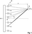
- FIG. 1 A diagram of a simple example of a (MIMO) FMCW radar sensor 10 is shown, which in this example has two transmitting antennas 12 and four receiving antennas 14 for MIMO measurements in a first field of view and a further antenna 15 with another field of view.
- the transmitting antennas 12, 15 are fed by a control and evaluation unit 16 and emit radar signals that are reflected on an object 18 and received by each of the receiving antennas 14.
- the field of view of the transmitting antenna 15 has a greater range and a narrower opening angle than the field of view of the transmitting antenna 12.
- the transmitting and receiving antennas can each consist of a patch antenna array.
- the received signals are mixed down to form baseband signals and evaluated in the control and evaluation unit 16.
- the radar sensor 10 is installed, for example, in the front of a motor vehicle and is used to measure distances d, angles and relative speeds v of objects 18, for example of vehicles driving ahead.
- the frequency of the transmission signal is modulated within a radar measurement with sequences of rising or falling ramps.
- a bistatic antenna system has been shown here in which the transmitting antennas 12, 15 are different from the receiving antennas 14, merely for reasons of clarity.
- a monostatic antenna concept can also be used, in which the same antennas are used for transmitting and receiving.
- the antennas 12, 14 are arranged in different positions in a direction in which the radar sensor 10 is angularly resolved.
- the receiving antennas 14 are arranged at regular intervals on a straight line (ULA; Uniform Linear Array).
- UAA Uniform Linear Array
- the transmitting antennas 12 the transmitting and receiving antennas not necessarily having to be arranged on the same straight line.
- the straight lines on which the antennas are arranged run horizontally.
- the antennas would be arranged on vertical straight lines.
- the radar sensor 10 is operated using the time-division multiplex method, measurements with different viewing areas being interwoven with one another over time.
- a maximum of one of the transmission antennas 12, 15 is active and sends the transmission signal.
- the activity phases of the individual antennas 12, 15 alternate cyclically. In Fig. 1 the case is shown in which only the lower of the two transmitting antennas 12 is active.
- Fig. 2 shows the transmission frequency f of the transmission signal 20 plotted over time t.
- the time offset of a further sequence i to a first sequence is referred to here and below as T1i, m, p.
- T1i, m, p the time offset of a further sequence i to a first sequence
- the successive ramps are shifted from one another by a time interval Tr2r.
- the time interval Tr2r is the same for all sequences of all viewing areas.
- the difference between the ramp center frequencies of successive ramps within a sequence is zero. Therefore all ramps have the same frequency curve.
- the ramp center frequency here corresponds to the average transmission frequency f 0 .
- Fig. 4 schematically shows a more detailed block diagram of the operations carried out by the control and evaluation unit 16 for determining the relative speed v, the distance d and the object angle ⁇ . To simplify the illustration, the processing is shown only for one receiving channel n, corresponding to a respective antenna 14.
- the received, scanned baseband signals b i, m, p are each subjected to a two-dimensional Fourier transformation (2D FFT).
- the first dimension corresponds to a transformation of the baseband signals received for the individual ramps.
- the second dimension corresponds to a transformation via the sequence of ramps, ie via the ramp index j.
- a two-dimensional spectrum X i (n, m, p) is thus obtained in the receiving channel n.
- the sizes of the respective transformations ie the respective numbers of bins (sampling points or support points), are preferably uniform for all spectra for the first dimension and uniform for all spectra for the second dimension.
- a phase difference between the complex amplitudes (spectral values) of a peak X 1 (k, l) occurring in the two-dimensional spectra at the same position (k, l) is determined.
- the phase difference ⁇ ⁇ 1 i , m , p is given by way of example in equation (2).
- power spectra are calculated from the obtained spectra X i (n, m, p) in a first function block 54 by forming the square of the absolute value of the respective spectral values.
- the power spectra are brought together point by point by summation or averaging to form an integrated two-dimensional power spectrum 56, 57.
- the position of a peak corresponding to a radar target 18 in the power spectrum 56, 57 which is indicated here as bin k, l, corresponds to the position of the peak in the individual spectra X i (n, m, p).
- c the speed of light
- F is the ramp stroke
- T is the ramp duration of a single ramp
- f 0 is the mean transmission frequency. If the frequency difference of successive ramps in a sequence is equal to zero, the peak position in the second dimension l only contains information about the relative speed v of the radar target.
- Fig. 3 shows schematically a diagram in which the relative speed v is plotted against the distance d.
- the linear relationship between v and d is shown as a straight line.
- the information about the relative speed of the radar target obtained from the sampling of the Doppler frequency is subject to an ambiguity according to the predetermined interval according to equation (1).
- the periodic values of the relative speed v determined from the frequency bin l are shown by dashed lines.
- the points of intersection with the vd line are marked. They correspond to possible pairs of values (v, d) of relative speed and distance of the radar target 18.
- the actual target, whose speed v is to be determined, is marked by a cross X.
- the ambiguity of the determined speed v is now resolved separately for the viewing areas p, as will be explained below.
- the information v * about the possible periodic values of the relative speed v is transferred to a second function block 58, as is the complex, two-dimensional spectra X i (n, m, p) of the partial measurements.
- the measurement vector a k, l (n, m, p) is defined accordingly, with the complex amplitudes (spectral values) at position k, l of the peak of the two-dimensional spectra of the partial measurements being used as components of the vector instead of the expected, speed-dependent complex values as given in equation (4); normalization takes place in the definition of the likelihood function.
- a k , l H n m p the hermetically adjoint vector to the measurement vector a k, l (n, m, p), i.e. a line vector in which the individual components are complex conjugate to the components of the vector a k, l (n, m, p).
- the likelihood function thus corresponds to a normalized sum of the squares of the absolute values of the (complex) scalar products between the measurement vector and the control vector of the transmission channels for a respective field of vision p, the summation being carried out over the different transmission channels is, where a transmission channel denotes a combination of receiving channel n and transmitting switching state m.
- the relative speed spectrum S (v, p) generally corresponds to a superposition of periodic functions of the relative speed v.
- the maxima of the likelihood function correspond to the most likely values of the parameter v.
- the relative speed spectrum S (v, p) is ambiguous.
- a maximum corresponds in each case to an on average optimal correspondence between the ideal phase shifts resulting for the relevant value of v and the measured phase shifts according to the measurement vectors.
- the ambiguity that results from the position of the peak can thus be resolved by the additional information from the phase relationship.
- an estimated value for the distance d belonging to the selected estimated value for the relative speed v is determined.
- the second function block 58 outputs the estimated values determined for the relative speed v and the distance d as well as the complex amplitudes X of the peaks for both viewing areas p to an angle estimator 60.
- the estimated relative speed v can be used to compensate for the phase shifts of the spectral values of the individual sequences with respect to a reference sequence caused by the relative speed v.
- the time signals (baseband signals) corresponding to the different sequences of ramps are thus initially processed separately.
- the detection of a radar target 18 then takes place in the power spectrum 56 obtained through non-coherent integration. Based on the detection and the complex amplitudes at the position of the peak then the ambiguity of the velocity v is resolved.
- the non-coherent merging of the spectra to form the power spectrum 56 is preferably carried out jointly for all reception channels and all transmission antennas. This improves peak detection.
- the evaluation device 16 can be set up to recognize such a disturbance of the measurement on the basis of a deviation of the maximum agreement which exceeds a threshold value, i.e. the maximum value of the possible values of the relative speed spectrum S (v, p), from the expected maximum value 1. The evaluation device 16 can then output an interference signal.
- a temporary multiple occupancy of a peak in the spectrum 56, 57 can, however, also be recognized by the fact that the evaluation device 16 detects an incorrect detection during a tracking of detected objects over several measurement cycles based on the estimated values of v and d of a radar target 18.
- Different modulation parameters of the ramps are preferably used for several radar measurements carried out one after the other, for example different center frequencies, ramp gradients, time intervals Tr2r and / or time offsets T1i, m, p. This means that accidental multiple assignments of peak positions can be limited to individual cases.
- receiving channels n into one receiving channel by means of digital beam forming.
- the spectra or measurement vectors of N receiving channels are coherent, that is to say taking the phase into account, for the respective field of view p and possibly the transmission switching state m respective weighting factors are added.
- S (v, p) the summations over n are accordingly omitted.
- the baseband signals b can also be output directly to the angle estimator 60, or spectra calculated separately from the baseband signals b can be output to the angle estimator.
Landscapes
- Engineering & Computer Science (AREA)
- Radar, Positioning & Navigation (AREA)
- Remote Sensing (AREA)
- Physics & Mathematics (AREA)
- Computer Networks & Wireless Communication (AREA)
- General Physics & Mathematics (AREA)
- Electromagnetism (AREA)
- Radar Systems Or Details Thereof (AREA)
Applications Claiming Priority (2)
| Application Number | Priority Date | Filing Date | Title |
|---|---|---|---|
| DE102014212281.3A DE102014212281A1 (de) | 2014-06-26 | 2014-06-26 | Radarmessverfahren mit unterschiedlichen Sichtbereichen |
| PCT/EP2015/058753 WO2015197223A1 (de) | 2014-06-26 | 2015-04-23 | Radarmessverfahren mit unterschiedlichen sichtbereichen |
Publications (2)
| Publication Number | Publication Date |
|---|---|
| EP3161513A1 EP3161513A1 (de) | 2017-05-03 |
| EP3161513B1 true EP3161513B1 (de) | 2020-10-28 |
Family
ID=52997446
Family Applications (1)
| Application Number | Title | Priority Date | Filing Date |
|---|---|---|---|
| EP15717897.1A Active EP3161513B1 (de) | 2014-06-26 | 2015-04-23 | Radarmessverfahren mit unterschiedlichen sichtbereichen |
Country Status (6)
| Country | Link |
|---|---|
| US (1) | US10557931B2 (ja) |
| EP (1) | EP3161513B1 (ja) |
| JP (1) | JP6372965B2 (ja) |
| CN (1) | CN107076835B (ja) |
| DE (1) | DE102014212281A1 (ja) |
| WO (1) | WO2015197223A1 (ja) |
Families Citing this family (22)
| Publication number | Priority date | Publication date | Assignee | Title |
|---|---|---|---|---|
| EP3121619A1 (en) * | 2015-07-22 | 2017-01-25 | Nxp B.V. | A radar system |
| DE102016100217A1 (de) * | 2016-01-06 | 2017-07-06 | Hella Kgaa Hueck & Co. | Radarsensor |
| WO2018035148A1 (en) | 2016-08-15 | 2018-02-22 | The Arizona Board Of Regents On Behalf Of The University Of Arizona | Novel automotive radar using 3d printed luneburg lens |
| US10473757B2 (en) * | 2016-12-19 | 2019-11-12 | Honeywell International Inc. | Moving target identification without special radar mode |
| DE102017200317A1 (de) * | 2017-01-11 | 2018-07-12 | Robert Bosch Gmbh | Radarsensor und Verfahren zur Bestimmung einer Relativgeschwindigkeit eines Radarziels |
| EP3410150B1 (en) * | 2017-05-30 | 2022-01-19 | Nxp B.V. | Apparatus for detection and ranging |
| DE102017120368A1 (de) * | 2017-09-05 | 2019-03-07 | HELLA GmbH & Co. KGaA | Verfahren und Vorrichtung zur Erzeugung eines modulierten Dauerstrichradarsignals |
| JP6923799B2 (ja) * | 2017-09-29 | 2021-08-25 | ミツミ電機株式会社 | レーダー装置 |
| DE102018200752A1 (de) * | 2018-01-18 | 2019-07-18 | Robert Bosch Gmbh | Verfahren und Vorrichtung zur Bewertung einer Winkelposition eines Objekts, und Fahrerassistenzsystem |
| DE102018200765A1 (de) * | 2018-01-18 | 2019-07-18 | Robert Bosch Gmbh | FMCW-Radarsensor |
| DE102018210083A1 (de) * | 2018-06-21 | 2019-12-24 | Robert Bosch Gmbh | Auswertevorrichtung und Verfahren zum Auswerten zumindest eines Radarsensors |
| KR102628655B1 (ko) * | 2018-06-29 | 2024-01-24 | 삼성전자주식회사 | 레이더 구동 장치 및 방법 |
| DE102018121987A1 (de) | 2018-09-10 | 2020-03-12 | Infineon Technologies Ag | Frequenzmoduliertes Dauerstrich-Radarsystem |
| US11092686B2 (en) * | 2018-09-19 | 2021-08-17 | Steradian Semiconductors Private Limited | Method, apparatus and device for doppler compensation in a time switched MIMO radar system |
| DE102018124582A1 (de) * | 2018-10-05 | 2020-04-09 | HELLA GmbH & Co. KGaA | Verfahren zur Erfassung bei einem Radarsystem |
| US11309636B2 (en) * | 2019-12-18 | 2022-04-19 | Waymo Llc | Antenna structure for reducing beam squint and sidelobes |
| DE102020107222A1 (de) * | 2020-03-17 | 2021-09-23 | HELLA GmbH & Co. KGaA | Verfahren zur Bestimmung einer Richtungsinformation |
| US12013484B2 (en) * | 2020-05-20 | 2024-06-18 | Infineon Technologies Ag | Radar receiving system and method for compensating a phase error between radar receiving circuits |
| EP3913391A1 (en) * | 2020-05-20 | 2021-11-24 | Infineon Technologies AG | Processing radar signals |
| CN112147587B (zh) * | 2020-09-28 | 2022-02-25 | 中国电波传播研究所(中国电子科技集团公司第二十二研究所) | 一种雷达波束方位中心海上标定方法 |
| EP4012443A1 (en) * | 2020-12-08 | 2022-06-15 | Veoneer Sweden AB | A vehicle radar system |
| KR20220168380A (ko) * | 2021-06-16 | 2022-12-23 | 삼성전자주식회사 | 안테나 모듈 및 이를 포함하는 전자 장치, 및 전자 장치의 동작 방법 |
Family Cites Families (20)
| Publication number | Priority date | Publication date | Assignee | Title |
|---|---|---|---|---|
| JP2768439B2 (ja) * | 1994-11-08 | 1998-06-25 | 本田技研工業株式会社 | Fm−cw方式マルチビームレーダー装置 |
| EP0730166B1 (de) | 1995-03-03 | 2001-06-27 | Siemens Aktiengesellschaft | Verfahren und Anordnung zur Verkehrserfassung mit einem Radargerät |
| US6577269B2 (en) * | 2000-08-16 | 2003-06-10 | Raytheon Company | Radar detection method and apparatus |
| CN1150407C (zh) | 2000-09-29 | 2004-05-19 | 清华大学 | 时分复用信道的天线阵系统及其信号处理方法 |
| US6606052B1 (en) * | 2002-03-07 | 2003-08-12 | Visteon Global Technologies, Inc. | Method and apparatus for detecting multiple objects with frequency modulated continuous wave radar |
| DE102004059915A1 (de) | 2004-12-13 | 2006-06-14 | Robert Bosch Gmbh | Radarsystem |
| DE102005012945A1 (de) * | 2005-03-21 | 2006-09-28 | Robert Bosch Gmbh | Verfahren und Vorrichtung zu Abstands- und Relativgeschwindigkeitsmessung mehrerer Objekte |
| JP4905457B2 (ja) * | 2006-11-01 | 2012-03-28 | 株式会社村田製作所 | レーダの物標検知方法、およびこの物標検知方法を用いたレーダ装置 |
| JP2009288223A (ja) * | 2008-06-02 | 2009-12-10 | Mitsubishi Electric Corp | レーダ装置 |
| JP5726852B2 (ja) * | 2009-04-06 | 2015-06-03 | コンティ テミック マイクロエレクトロニック ゲゼルシャフト ミットベシュレンクテル ハフツングConti Temic microelectronic GmbH | 送信信号と受信信号とを分離しかつ妨害放射を抑制する装置を持つレーダシステム及び方法 |
| JP5468304B2 (ja) | 2009-05-20 | 2014-04-09 | 株式会社東芝 | レーダ装置 |
| DE102010030289A1 (de) * | 2010-06-21 | 2011-12-22 | Robert Bosch Gmbh | Radarsensor und Verfahren zum Betreiben eines Radarsensors |
| US8902103B2 (en) * | 2011-03-16 | 2014-12-02 | Electronics And Telecommunications Research Institute | Radar apparatus supporting short and long range radar operation |
| DE102012008350A1 (de) * | 2012-04-19 | 2013-10-24 | S.M.S Smart Microwave Sensors Gmbh | Verfahren und Vorrichtung zur Abstimmung von Abstand und Radialgeschwindigkeit eines Objekts mittels Radarsignalen |
| ITTO20120417A1 (it) * | 2012-05-09 | 2013-11-10 | St Microelectronics Srl | Procedimento e dispositivi per elaborare segnali radar, ad esempio per sistemi di sicurezza stradale, relativo prodotto informatico |
| DE102012212888A1 (de) * | 2012-07-23 | 2014-01-23 | Robert Bosch Gmbh | Detektion von Radarobjekten mit einem Radarsensor eines Kraftfahrzeugs |
| DE102012220879A1 (de) * | 2012-11-15 | 2014-05-15 | Robert Bosch Gmbh | Rapid-Chirps-FMCW-Radar |
| TWI472790B (zh) * | 2013-05-31 | 2015-02-11 | Wistron Neweb Corp | 信號產生方法及雷達系統 |
| DE102013210256A1 (de) * | 2013-06-03 | 2014-12-04 | Robert Bosch Gmbh | Interferenzunterdrückung bei einem fmcw-radar |
| DE102014104273A1 (de) * | 2014-03-26 | 2015-10-01 | Friedrich-Alexander-Universität Erlangen-Nürnberg | Verfahren in einem Radarsystem, Radarsystem bzw. Vorrichtung eines Radarsystems |
-
2014
- 2014-06-26 DE DE102014212281.3A patent/DE102014212281A1/de not_active Withdrawn
-
2015
- 2015-04-23 CN CN201580034470.2A patent/CN107076835B/zh active Active
- 2015-04-23 EP EP15717897.1A patent/EP3161513B1/de active Active
- 2015-04-23 US US15/319,417 patent/US10557931B2/en active Active
- 2015-04-23 JP JP2017518412A patent/JP6372965B2/ja active Active
- 2015-04-23 WO PCT/EP2015/058753 patent/WO2015197223A1/de active Application Filing
Non-Patent Citations (1)
| Title |
|---|
| None * |
Also Published As
| Publication number | Publication date |
|---|---|
| WO2015197223A1 (de) | 2015-12-30 |
| CN107076835A (zh) | 2017-08-18 |
| US10557931B2 (en) | 2020-02-11 |
| DE102014212281A1 (de) | 2015-12-31 |
| JP2017522575A (ja) | 2017-08-10 |
| CN107076835B (zh) | 2020-09-22 |
| EP3161513A1 (de) | 2017-05-03 |
| JP6372965B2 (ja) | 2018-08-15 |
| US20170131393A1 (en) | 2017-05-11 |
Similar Documents
| Publication | Publication Date | Title |
|---|---|---|
| EP3161513B1 (de) | Radarmessverfahren mit unterschiedlichen sichtbereichen | |
| EP3161514B1 (de) | Mimo-radarmessverfahren | |
| EP3161510B1 (de) | Radarmessverfahren | |
| EP3377915B1 (de) | Radarsystem mit verschachtelt seriellem senden und parallelem empfangen | |
| EP2294450B1 (de) | Radarsystem mit überlappenden sende- und empfangsantennen | |
| EP2659284B1 (de) | Radarsensor für kraftfahrzeuge | |
| EP3014297B1 (de) | Winkelauflösender fmcw-radarsensor | |
| WO2018108359A1 (de) | Mimo-radarsensor für kraftfahrzeuge | |
| EP3155444B1 (de) | Verfahren zur objektortung mit einem fmcw-radar | |
| EP3596488B1 (de) | Verfahren, vorrichtung und computerprogrammprodukt zum ermitteln von transversalen relativgeschwindigkeitskomponenten von radarzielen | |
| DE102017200706A1 (de) | Mehrfach unterabgetastetes Chirp-Sequence-Radar | |
| EP3752858B1 (de) | Winkelauflösender breitbandiger radarsensor für kraftfahrzeuge | |
| DE102012212888A1 (de) | Detektion von Radarobjekten mit einem Radarsensor eines Kraftfahrzeugs | |
| WO2015028175A1 (de) | Radarsensor für kraftfahrzeuge | |
| DE102009047561A1 (de) | Antenneneinrichtung für eine Radarsensorvorrichtung | |
| DE102018124503A1 (de) | Radarsystem für ein Fahrzeug | |
| EP3470874A1 (de) | Radar-verfahren und -system zur bestimmung der winkellage, des ortes und/oder der, insbesondere vektoriellen, geschwindigkeit eines zieles | |
| WO2019158253A1 (de) | Schätzung von quergeschwindigkeiten oder kartesischen geschwindigkeiten von punktzielen mit einem radarsensor | |
| EP3752859B1 (de) | Winkelschätzung und mehrdeutigkeitsauflösung von radarsensoren für kraftfahrzeuge mit grossem antennenarray | |
| DE102019219649A1 (de) | Kooperatives Radarsensorsystem mit winkelauflösenden Radarsensoren | |
| DE102021213495A1 (de) | Radarmessverfahren | |
| DE102022205149A1 (de) | Verwendung eines Radarsensors mit einem Hohlleiterantennenarray für ein Verfahren zur Bestimmung eines Eigengeschwindigkeits-Schätzwerts und eines Winkel-Schätzwerts von Zielen | |
| EP3752852A1 (de) | Schätzung von kartesischen geschwindigkeiten von ausgedehnten radarobjekten mit einem radarsensor |
Legal Events
| Date | Code | Title | Description |
|---|---|---|---|
| STAA | Information on the status of an ep patent application or granted ep patent |
Free format text: STATUS: THE INTERNATIONAL PUBLICATION HAS BEEN MADE |
|
| PUAI | Public reference made under article 153(3) epc to a published international application that has entered the european phase |
Free format text: ORIGINAL CODE: 0009012 |
|
| STAA | Information on the status of an ep patent application or granted ep patent |
Free format text: STATUS: REQUEST FOR EXAMINATION WAS MADE |
|
| 17P | Request for examination filed |
Effective date: 20170126 |
|
| AK | Designated contracting states |
Kind code of ref document: A1 Designated state(s): AL AT BE BG CH CY CZ DE DK EE ES FI FR GB GR HR HU IE IS IT LI LT LU LV MC MK MT NL NO PL PT RO RS SE SI SK SM TR |
|
| AX | Request for extension of the european patent |
Extension state: BA ME |
|
| DAV | Request for validation of the european patent (deleted) | ||
| DAX | Request for extension of the european patent (deleted) | ||
| RAP1 | Party data changed (applicant data changed or rights of an application transferred) |
Owner name: ROBERT BOSCH GMBH |
|
| RIC1 | Information provided on ipc code assigned before grant |
Ipc: G01S 13/32 20060101ALI20200508BHEP Ipc: G01S 13/931 20200101ALN20200508BHEP Ipc: G01S 13/58 20060101ALI20200508BHEP Ipc: G01S 13/42 20060101ALI20200508BHEP Ipc: G01S 7/35 20060101ALI20200508BHEP Ipc: G01S 13/34 20060101AFI20200508BHEP Ipc: G01S 13/536 20060101ALN20200508BHEP Ipc: G01S 13/02 20060101ALI20200508BHEP |
|
| RIC1 | Information provided on ipc code assigned before grant |
Ipc: G01S 13/32 20060101ALI20200520BHEP Ipc: G01S 13/536 20060101ALN20200520BHEP Ipc: G01S 7/35 20060101ALI20200520BHEP Ipc: G01S 13/02 20060101ALI20200520BHEP Ipc: G01S 13/34 20060101AFI20200520BHEP Ipc: G01S 13/42 20060101ALI20200520BHEP Ipc: G01S 13/58 20060101ALI20200520BHEP Ipc: G01S 13/931 20200101ALN20200520BHEP |
|
| GRAP | Despatch of communication of intention to grant a patent |
Free format text: ORIGINAL CODE: EPIDOSNIGR1 |
|
| STAA | Information on the status of an ep patent application or granted ep patent |
Free format text: STATUS: GRANT OF PATENT IS INTENDED |
|
| RIC1 | Information provided on ipc code assigned before grant |
Ipc: G01S 13/58 20060101ALI20200608BHEP Ipc: G01S 13/42 20060101ALI20200608BHEP Ipc: G01S 13/02 20060101ALI20200608BHEP Ipc: G01S 13/536 20060101ALN20200608BHEP Ipc: G01S 7/35 20060101ALI20200608BHEP Ipc: G01S 13/32 20060101ALI20200608BHEP Ipc: G01S 13/34 20060101AFI20200608BHEP Ipc: G01S 13/931 20200101ALN20200608BHEP |
|
| INTG | Intention to grant announced |
Effective date: 20200706 |
|
| GRAS | Grant fee paid |
Free format text: ORIGINAL CODE: EPIDOSNIGR3 |
|
| GRAA | (expected) grant |
Free format text: ORIGINAL CODE: 0009210 |
|
| STAA | Information on the status of an ep patent application or granted ep patent |
Free format text: STATUS: THE PATENT HAS BEEN GRANTED |
|
| AK | Designated contracting states |
Kind code of ref document: B1 Designated state(s): AL AT BE BG CH CY CZ DE DK EE ES FI FR GB GR HR HU IE IS IT LI LT LU LV MC MK MT NL NO PL PT RO RS SE SI SK SM TR |
|
| REG | Reference to a national code |
Ref country code: GB Ref legal event code: FG4D Free format text: NOT ENGLISH |
|
| REG | Reference to a national code |
Ref country code: CH Ref legal event code: EP |
|
| REG | Reference to a national code |
Ref country code: DE Ref legal event code: R096 Ref document number: 502015013706 Country of ref document: DE |
|
| REG | Reference to a national code |
Ref country code: AT Ref legal event code: REF Ref document number: 1328759 Country of ref document: AT Kind code of ref document: T Effective date: 20201115 |
|
| REG | Reference to a national code |
Ref country code: IE Ref legal event code: FG4D Free format text: LANGUAGE OF EP DOCUMENT: GERMAN |
|
| REG | Reference to a national code |
Ref country code: SE Ref legal event code: TRGR |
|
| REG | Reference to a national code |
Ref country code: NL Ref legal event code: MP Effective date: 20201028 |
|
| PG25 | Lapsed in a contracting state [announced via postgrant information from national office to epo] |
Ref country code: GR Free format text: LAPSE BECAUSE OF FAILURE TO SUBMIT A TRANSLATION OF THE DESCRIPTION OR TO PAY THE FEE WITHIN THE PRESCRIBED TIME-LIMIT Effective date: 20210129 Ref country code: PT Free format text: LAPSE BECAUSE OF FAILURE TO SUBMIT A TRANSLATION OF THE DESCRIPTION OR TO PAY THE FEE WITHIN THE PRESCRIBED TIME-LIMIT Effective date: 20210301 Ref country code: NL Free format text: LAPSE BECAUSE OF FAILURE TO SUBMIT A TRANSLATION OF THE DESCRIPTION OR TO PAY THE FEE WITHIN THE PRESCRIBED TIME-LIMIT Effective date: 20201028 Ref country code: NO Free format text: LAPSE BECAUSE OF FAILURE TO SUBMIT A TRANSLATION OF THE DESCRIPTION OR TO PAY THE FEE WITHIN THE PRESCRIBED TIME-LIMIT Effective date: 20210128 Ref country code: RS Free format text: LAPSE BECAUSE OF FAILURE TO SUBMIT A TRANSLATION OF THE DESCRIPTION OR TO PAY THE FEE WITHIN THE PRESCRIBED TIME-LIMIT Effective date: 20201028 Ref country code: FI Free format text: LAPSE BECAUSE OF FAILURE TO SUBMIT A TRANSLATION OF THE DESCRIPTION OR TO PAY THE FEE WITHIN THE PRESCRIBED TIME-LIMIT Effective date: 20201028 |
|
| REG | Reference to a national code |
Ref country code: LT Ref legal event code: MG4D |
|
| PG25 | Lapsed in a contracting state [announced via postgrant information from national office to epo] |
Ref country code: ES Free format text: LAPSE BECAUSE OF FAILURE TO SUBMIT A TRANSLATION OF THE DESCRIPTION OR TO PAY THE FEE WITHIN THE PRESCRIBED TIME-LIMIT Effective date: 20201028 Ref country code: BG Free format text: LAPSE BECAUSE OF FAILURE TO SUBMIT A TRANSLATION OF THE DESCRIPTION OR TO PAY THE FEE WITHIN THE PRESCRIBED TIME-LIMIT Effective date: 20210128 Ref country code: PL Free format text: LAPSE BECAUSE OF FAILURE TO SUBMIT A TRANSLATION OF THE DESCRIPTION OR TO PAY THE FEE WITHIN THE PRESCRIBED TIME-LIMIT Effective date: 20201028 Ref country code: LV Free format text: LAPSE BECAUSE OF FAILURE TO SUBMIT A TRANSLATION OF THE DESCRIPTION OR TO PAY THE FEE WITHIN THE PRESCRIBED TIME-LIMIT Effective date: 20201028 Ref country code: IS Free format text: LAPSE BECAUSE OF FAILURE TO SUBMIT A TRANSLATION OF THE DESCRIPTION OR TO PAY THE FEE WITHIN THE PRESCRIBED TIME-LIMIT Effective date: 20210228 |
|
| PG25 | Lapsed in a contracting state [announced via postgrant information from national office to epo] |
Ref country code: HR Free format text: LAPSE BECAUSE OF FAILURE TO SUBMIT A TRANSLATION OF THE DESCRIPTION OR TO PAY THE FEE WITHIN THE PRESCRIBED TIME-LIMIT Effective date: 20201028 |
|
| REG | Reference to a national code |
Ref country code: DE Ref legal event code: R097 Ref document number: 502015013706 Country of ref document: DE |
|
| PG25 | Lapsed in a contracting state [announced via postgrant information from national office to epo] |
Ref country code: SM Free format text: LAPSE BECAUSE OF FAILURE TO SUBMIT A TRANSLATION OF THE DESCRIPTION OR TO PAY THE FEE WITHIN THE PRESCRIBED TIME-LIMIT Effective date: 20201028 Ref country code: EE Free format text: LAPSE BECAUSE OF FAILURE TO SUBMIT A TRANSLATION OF THE DESCRIPTION OR TO PAY THE FEE WITHIN THE PRESCRIBED TIME-LIMIT Effective date: 20201028 Ref country code: CZ Free format text: LAPSE BECAUSE OF FAILURE TO SUBMIT A TRANSLATION OF THE DESCRIPTION OR TO PAY THE FEE WITHIN THE PRESCRIBED TIME-LIMIT Effective date: 20201028 Ref country code: SK Free format text: LAPSE BECAUSE OF FAILURE TO SUBMIT A TRANSLATION OF THE DESCRIPTION OR TO PAY THE FEE WITHIN THE PRESCRIBED TIME-LIMIT Effective date: 20201028 Ref country code: RO Free format text: LAPSE BECAUSE OF FAILURE TO SUBMIT A TRANSLATION OF THE DESCRIPTION OR TO PAY THE FEE WITHIN THE PRESCRIBED TIME-LIMIT Effective date: 20201028 Ref country code: LT Free format text: LAPSE BECAUSE OF FAILURE TO SUBMIT A TRANSLATION OF THE DESCRIPTION OR TO PAY THE FEE WITHIN THE PRESCRIBED TIME-LIMIT Effective date: 20201028 |
|
| PG25 | Lapsed in a contracting state [announced via postgrant information from national office to epo] |
Ref country code: DK Free format text: LAPSE BECAUSE OF FAILURE TO SUBMIT A TRANSLATION OF THE DESCRIPTION OR TO PAY THE FEE WITHIN THE PRESCRIBED TIME-LIMIT Effective date: 20201028 |
|
| PLBE | No opposition filed within time limit |
Free format text: ORIGINAL CODE: 0009261 |
|
| STAA | Information on the status of an ep patent application or granted ep patent |
Free format text: STATUS: NO OPPOSITION FILED WITHIN TIME LIMIT |
|
| 26N | No opposition filed |
Effective date: 20210729 |
|
| PG25 | Lapsed in a contracting state [announced via postgrant information from national office to epo] |
Ref country code: AL Free format text: LAPSE BECAUSE OF FAILURE TO SUBMIT A TRANSLATION OF THE DESCRIPTION OR TO PAY THE FEE WITHIN THE PRESCRIBED TIME-LIMIT Effective date: 20201028 Ref country code: IT Free format text: LAPSE BECAUSE OF FAILURE TO SUBMIT A TRANSLATION OF THE DESCRIPTION OR TO PAY THE FEE WITHIN THE PRESCRIBED TIME-LIMIT Effective date: 20201028 |
|
| PG25 | Lapsed in a contracting state [announced via postgrant information from national office to epo] |
Ref country code: MC Free format text: LAPSE BECAUSE OF FAILURE TO SUBMIT A TRANSLATION OF THE DESCRIPTION OR TO PAY THE FEE WITHIN THE PRESCRIBED TIME-LIMIT Effective date: 20201028 Ref country code: SI Free format text: LAPSE BECAUSE OF FAILURE TO SUBMIT A TRANSLATION OF THE DESCRIPTION OR TO PAY THE FEE WITHIN THE PRESCRIBED TIME-LIMIT Effective date: 20201028 |
|
| PG25 | Lapsed in a contracting state [announced via postgrant information from national office to epo] |
Ref country code: LU Free format text: LAPSE BECAUSE OF NON-PAYMENT OF DUE FEES Effective date: 20210423 |
|
| REG | Reference to a national code |
Ref country code: BE Ref legal event code: MM Effective date: 20210430 |
|
| PG25 | Lapsed in a contracting state [announced via postgrant information from national office to epo] |
Ref country code: LI Free format text: LAPSE BECAUSE OF NON-PAYMENT OF DUE FEES Effective date: 20210430 Ref country code: CH Free format text: LAPSE BECAUSE OF NON-PAYMENT OF DUE FEES Effective date: 20210430 |
|
| PG25 | Lapsed in a contracting state [announced via postgrant information from national office to epo] |
Ref country code: IE Free format text: LAPSE BECAUSE OF NON-PAYMENT OF DUE FEES Effective date: 20210423 |
|
| PG25 | Lapsed in a contracting state [announced via postgrant information from national office to epo] |
Ref country code: IS Free format text: LAPSE BECAUSE OF FAILURE TO SUBMIT A TRANSLATION OF THE DESCRIPTION OR TO PAY THE FEE WITHIN THE PRESCRIBED TIME-LIMIT Effective date: 20210228 |
|
| REG | Reference to a national code |
Ref country code: AT Ref legal event code: MM01 Ref document number: 1328759 Country of ref document: AT Kind code of ref document: T Effective date: 20210423 |
|
| PG25 | Lapsed in a contracting state [announced via postgrant information from national office to epo] |
Ref country code: BE Free format text: LAPSE BECAUSE OF NON-PAYMENT OF DUE FEES Effective date: 20210430 |
|
| PG25 | Lapsed in a contracting state [announced via postgrant information from national office to epo] |
Ref country code: AT Free format text: LAPSE BECAUSE OF NON-PAYMENT OF DUE FEES Effective date: 20210423 |
|
| PG25 | Lapsed in a contracting state [announced via postgrant information from national office to epo] |
Ref country code: HU Free format text: LAPSE BECAUSE OF FAILURE TO SUBMIT A TRANSLATION OF THE DESCRIPTION OR TO PAY THE FEE WITHIN THE PRESCRIBED TIME-LIMIT; INVALID AB INITIO Effective date: 20150423 |
|
| PG25 | Lapsed in a contracting state [announced via postgrant information from national office to epo] |
Ref country code: CY Free format text: LAPSE BECAUSE OF FAILURE TO SUBMIT A TRANSLATION OF THE DESCRIPTION OR TO PAY THE FEE WITHIN THE PRESCRIBED TIME-LIMIT Effective date: 20201028 |
|
| PGFP | Annual fee paid to national office [announced via postgrant information from national office to epo] |
Ref country code: FR Payment date: 20230417 Year of fee payment: 9 Ref country code: DE Payment date: 20230627 Year of fee payment: 9 |
|
| PGFP | Annual fee paid to national office [announced via postgrant information from national office to epo] |
Ref country code: SE Payment date: 20230419 Year of fee payment: 9 |
|
| PGFP | Annual fee paid to national office [announced via postgrant information from national office to epo] |
Ref country code: GB Payment date: 20230420 Year of fee payment: 9 |
|
| PG25 | Lapsed in a contracting state [announced via postgrant information from national office to epo] |
Ref country code: MK Free format text: LAPSE BECAUSE OF FAILURE TO SUBMIT A TRANSLATION OF THE DESCRIPTION OR TO PAY THE FEE WITHIN THE PRESCRIBED TIME-LIMIT Effective date: 20201028 |