EP3159267B1 - Entleerungsrutsche mit balkenstruktur bestehend aus vierpunkt-querschnitt - Google Patents
Entleerungsrutsche mit balkenstruktur bestehend aus vierpunkt-querschnitt Download PDFInfo
- Publication number
- EP3159267B1 EP3159267B1 EP16194317.0A EP16194317A EP3159267B1 EP 3159267 B1 EP3159267 B1 EP 3159267B1 EP 16194317 A EP16194317 A EP 16194317A EP 3159267 B1 EP3159267 B1 EP 3159267B1
- Authority
- EP
- European Patent Office
- Prior art keywords
- transverse dimension
- section
- point
- inflatable
- rail beam
- Prior art date
- Legal status (The legal status is an assumption and is not a legal conclusion. Google has not performed a legal analysis and makes no representation as to the accuracy of the status listed.)
- Active
Links
Images


Classifications
-
- B—PERFORMING OPERATIONS; TRANSPORTING
- B64—AIRCRAFT; AVIATION; COSMONAUTICS
- B64C—AEROPLANES; HELICOPTERS
- B64C1/00—Fuselages; Constructional features common to fuselages, wings, stabilising surfaces or the like
- B64C1/24—Steps mounted on, and retractable within, fuselages
-
- B—PERFORMING OPERATIONS; TRANSPORTING
- B64—AIRCRAFT; AVIATION; COSMONAUTICS
- B64D—EQUIPMENT FOR FITTING IN OR TO AIRCRAFT; FLIGHT SUITS; PARACHUTES; ARRANGEMENT OR MOUNTING OF POWER PLANTS OR PROPULSION TRANSMISSIONS IN AIRCRAFT
- B64D25/00—Emergency apparatus or devices, not otherwise provided for
- B64D25/08—Ejecting or escaping means
- B64D25/14—Inflatable escape chutes
Definitions
- an inflatable aircraft evacuation slide comprising inflatable support beams requires sufficient strength in the beams to withstand high wind conditions and heavy loads imposed on the slide.
- a slide should have sufficient beam strength to withstand wind speeds as high as 11.8-15.4 m/s (15-30 knots), and to support sandbags weighing a total of ⁇ 231 kg (510 lbs) per slide lane. Therefore, inflatable support beams of typical evacuation slides require both vertical and horizontal strength in the support beams.
- the slide including an inflation source such as a compressed air cylinder, is typically packed within a small space in the aircraft, a reduction in the size of the slide and air cylinder, is desirable.
- GB 1403504 relates to an inflatable escape slide.
- WO 2010/142922 A1 relates to an inflatable marine evacuation slide.
- an inflatable slide comprising: an elongated member comprising a sliding surface; and a support structure supporting the elongated member, the support structure comprising a first rail beam and a second rail beam bordering opposites sides of the elongated member, wherein the first rail beam and the second rail beam are inflatable, wherein the first rail beam and the second rail beam each have a four-point cross section, wherein the four-point cross section is defined by a pair of opposite arcuate sections comprising a first inflatable arcuate section having a first peak point and a second inflatable arcuate section having a second peak point, and a pair of opposite arcuate sections comprising a third inflatable arcuate section having a third peak point and a fourth inflatable arcuate section having a fourth peak point, wherein a first large transverse dimension between the first peak point and the second peak point intersects a second large transverse dimension between the third peak point and the fourth peak point, and wherein the four-point cross section is further
- the four-point cross section of each of the first and second beams is made from three or fewer chambers.
- the inflatable slide is an aircraft emergency evacuation slide.
- the first large transverse dimension equals the second large transverse dimension. In one embodiment, the first large transverse dimension and the second large transverse dimension intersect at about 90 degrees. In one embodiment, a first small transverse dimension between the first indent and the second indent intersects a second small transverse dimension between the third indent and the fourth indent at about 90 degrees. In one embodiment, the first small transverse dimension equals the second small transverse dimension. In one embodiment, the first small transverse dimension intersects the second small transverse dimension at about 90 degrees.
- the four-point cross section is symmetrical about a central point, wherein the first large transverse dimension equals the second large transverse dimension, defining a large diameter of the four-point cross section, and the first small transverse dimension equals the second small transverse dimension, defining a small diameter of the four-point cross section, which is smaller than the large diameter.
- a ratio between the small diameter to the large diameter is between 3:5 and 4:6. In one embodiment, the ratio between the small diameter to the large diameter is 4:5.
- the sliding surface is bonded to the first rail beam at one of the first peak point, the second peak point, the third peak point, or the fourth peak point of the four-point cross section of the first rail beam, and wherein the sliding surface is bonded to the second rail beam at one of the first peak point, the second peak point, the third peak point, or the fourth peak point of the four-point cross section of the second rail beam.
- the support structure may be inflatable comprising: a flexible material formed into an inflatable elongated configuration having the cross section which when inflated defines the four arcuate sections.
- Each peak point may be defined by the largest radial extent of an outer surface of the inflatable support structure at each of the four arcuate sections.
- the first pair of opposing peak points define the first large transverse dimension and the second pair of opposing peak points define the second large transverse dimension.
- the four indentations may be defined perimetrically between the peak points each of the four indentations having an indent point defined by the smallest radial extent of the outer surface of the inflatable support structure between perimetrically adjacent peak points, a first pair of opposing indent points defining a first small transverse dimension and a second pair of opposing indent point defining a second small transverse dimension.
- the flexible material when inflated, forms at least one of a first rail beam and a second rail beam, the first rail beam and the second rail beam providing a support structure for an elongated member comprising a sliding surface of the support structure, wherein the first rail beam and the second rail beam border opposite sides of the elongated member comprising the sliding surface.
- the flexible material when inflated, further forms a ground rail beam bordering on a bottom side of the elongated member.
- the four arcuate sections of the flexible material are formed from more than one continuous gas fill chamber.
- the flexible material forms at least a portion of an inflatable slide.
- the four-point cross section beam structure may comprise at least one continuous gas fill chamber.
- the four-point cross section is symmetrical about a central point, wherein the first large transverse dimension has a radial extent approximately equal to the radial extent of the second large transverse dimension, defining a large radial extent of the four-point cross section, and wherein the first large transverse dimension intersects the second large transverse dimension at about 90 degrees, wherein the first small transverse dimension has a radial extent approximately equal to the radial extent of the second small transverse dimension, defining a small radial extent of the four-point cross section, and wherein the first small transverse dimension and the second small transverse dimension intersect at about 90 degrees.
- a ratio between the small radial extent to the large radial extent is between 3:5 and 4:6.
- a beam structure 400 shown in Figure 1A , comprising a four-point cross section 200 (see Figure 2 ) for an inflatable slide 100 (shown in an inflated state in Figure 1B ).
- the beam structure 400 comprises a flexible material formed into an inflatable elongated configuration having a cross section of which when inflated defines four inflatable arcuate sections of beam structure 400.
- the beam structure 400 (also referred to as "four-point cross section beam structure 400") has greater beam strength and provides greater structural support than an inflatable beam having a traditional circular cross section.
- the inflatable slide 100 comprising beam structure 400, generally includes an elongated member 120 having a sliding surface 102, supported by a support structure 101 which comprises at least two rail beams comprising a first rail beam 104 and a second rail beam 106, which are inflatable, and have a four-point cross section 200, as shown in Figure 2 .
- the first rail beam 104 and the second rail beam 106 border opposite sides of the elongated member 120.
- the inflatable slide 100 comprising beam structure 400 may be used for emergency evacuation.
- the inflatable slide 100 is used for emergency evacuation of an aircraft 108 and is configured to pack within a compartment of the aircraft 108 (i.e. an aircraft door, a slide bustle, etc.).
- the inflatable slide 100 may be packed with an inflation source such as a compressed air cylinder 111.
- the inflatable slide 100 may be inflated at a pressure of between 13.8 kPa (2psi) and 68.9 kPa (10psi).
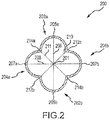
- the four-point cross section 200 of beam structure 400 has a clover-like geometry, and may be defined by a longitudinal pair of opposite arcuate sections comprising a first inflatable arcuate section 202a and a second inflatable arcuate section 202b; and a transverse pair of opposite arcuate sections comprising a third inflatable arcuate section 204a and a fourth inflatable arcuate section 204b, wherein a first large transverse dimension 206 defined between a first peak point 205a of the first arcuate section 202a and a second peak point 205b of the second arcuate section 202b, intersects with a second large transverse dimension 208) defined between a third peak point 207a of the third arcuate section 204a and a fourth peak point 207b of the fourth arcuate section 204b.
- the first large transverse dimension 206 equals the second large transverse dimension 208 (defining a large dimension of four-point cross section 200). According to various embodiments, the first large transverse dimension 206 intersects the second large transverse dimension 208 at about 90 degrees, wherein the term "about” in this context only means +/- 5 degrees.
- four-point cross section 200 is further defined by a first indent 212a formed between the first arcuate section 202a and the fourth arcuate section 204b; a second indent 212b formed between the second arcuate section 202b and the third arcuate section 204a; a third indent 214a formed between the third arcuate section 204a and the first arcuate section 202a; and a fourth indent 214b formed between the second arcuate section 202b and the fourth arcuate section 204b.
- the first small transverse dimension 210 equals the second small transverse dimension 211(defining a small diameter of four-point cross section 200).
- the first small transverse dimension 210 intersects the second small transverse dimension 211at about 90 degrees, wherein the term "about” in this context only means +/- 5 degrees.
- four-point cross section 200 is symmetrical about a central point 201, wherein the first large transverse dimension 206 equals the second large transverse dimension 208, and wherein the first small transverse dimension 210 equals the second small diameter 211.
- the ratio between the small diameter to the large diameter is between 3:5 and 4:6.
- the ratio of the small diameter to the large diameter is 4:5.
- a gas filled beam with the beam structure 400 may have a 1%-5% increase in support strength and a reduced inflatable interior volume.
- beam structure 400 including a small diameter of 0.4064m (16 inches) and a large diameter of 0.508m (20 inches) was found to have a 3.3% increase in support strength, and a 13% reduction of inflatable volume as compared to a circular cross section beam structure with a 0.508m (20 inches) diameter.
- the resultant volume reduction is advantageous for packing the inflatable slide 100, into a limited amount of space, as the sizes of both the inflatable slide 100 and compressed air cylinder 111 are reduced.
- the beam structure 400 may comprise one continuous gas fillable chamber. According to various embodiments, beam structure 400 may comprise more than one air fill chambers.
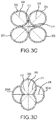
- beam structure 400 may be formed by bonding together two beams having an I-cross section 300 ("I-cross section beams") or two beams having an H-cross section 302 ("H-cross section beams"), shown in Figures 3A and 3B , according to various embodiments.
- beam structure 400 may be formed by bonding together four beams, having circular cross sections 303, as shown in Figure 3C .
- beam structure 400 may be formed by bonding tube segments 304A and 304B on opposite sides of a tube having an H-cross section 302, or an I-cross section 300, as shown in Figure 3D .
- the sliding surface 102 may be bonded between the first rail beam 104 and the second rail beam 106.
- sliding surface 102 may be bonded at or around a peak point (i.e. first peak point 205a, second peak point 205b, third peak point 207a, or fourth peak point 207b, shown in Figure 2 ) of four-point cross section 200, as shown in Figure 1 .
- the sliding surface 102 may comprise a flexible fabric material such as a urethane rip stop material and/or a nylon based cloth with a urethane coating.
- the support structure 101 may further comprise a ground rail beam 109 bordering a bottom side of the sliding surface 102.
- ground rail beam 109 may have a four-point cross section, similar to the four-point cross section 200 of the first rail beam 104 and the second rail beam 106.
- ground rail beam 109 may have a circular or other cross section configuration, wherein the first rail beam 104 and the second rail beam 106 may each comprise the four-point cross section 200.
- the first rail beam 104 and the second rail beam 106 may be bonded to, or otherwise coupled with, the ground rail beam 109.
- the first rail beam 104, the second rail beam 106, and the ground rail beam 109 may form a continuous air filled unit (in response to inflation), in bordering engagement with sliding surface 102.
- the support structure 101 may further comprise other inflatable structural components, such as transverse support beams, drop down support(s), a slide ramp, etc., which traditionally have a circular cross section.
- any one of such other inflatable structural components may also comprise four-point cross section 200.
- any one of such other inflatable structural components may be bonded to, or otherwise coupled with, the first rail beam 104 and the second rail beam 106, or may form a continuous air filled unit therewith, according to various embodiments. Specific embodiments may take into account factors such as available material, required/ desired operational parameters, cost, slide design and size, etc.
- references to "various embodiments”, “one embodiment”, “an embodiment”, “an example embodiment”, etc., indicate that the embodiment described may include a particular feature, structure, or characteristic, but every embodiment may not necessarily include the particular feature, structure, or characteristic. Moreover, such phrases are not necessarily referring to the same embodiment.
Landscapes
- Engineering & Computer Science (AREA)
- Aviation & Aerospace Engineering (AREA)
- Business, Economics & Management (AREA)
- Emergency Management (AREA)
- Mechanical Engineering (AREA)
- Air Bags (AREA)
- Tents Or Canopies (AREA)
- Rod-Shaped Construction Members (AREA)
- Buildings Adapted To Withstand Abnormal External Influences (AREA)
Claims (14)
- Aufblasbare Rutsche (100), Folgendes umfassend:ein längliches Bauteil (120), das eine Rutschoberfläche umfasst; undeine Stützstruktur (101), die das längliche Bauteil (120) stützt, wobei die Stützstruktur einen ersten Schienenbalken und einen zweiten Schienenbalken umfasst, die gegenüberliegende Seiten des länglichen Bauteils begrenzen,wobei der erste Schienenbalken (104) und der zweite Schienenbalken (106) aufblasbar sind,wobei der erste Schienenbalken (104) und der zweite Schienenbalken (106) jeweils einen Vierpunktquerschnitt aufweisen,wobei der Vierpunktquerschnitt durch ein erstes Paar von gegenüberliegenden bogenförmigen Abschnitten definiert wird, die einen ersten aufblasbaren bogenförmigen Abschnitt (202a) umfassen, der einen ersten Scheitelpunkt aufweist, und einen zweiten aufblasbaren bogenförmigen Abschnitt (202b), der einen zweiten Scheitelpunkt aufweist, wobei der erste und der zweite Scheitelpunkt einen ersten großen Querschnitt definieren, und ein transversales Paar von gegenüberliegenden bogenförmigen Abschnitten, die einen dritten aufblasbaren bogenförmigen Abschnitt (204a) umfassen, der einen dritten Scheitelpunkt aufweist, und einen vierten aufblasbaren bogenförmigen Abschnitt (204b), der einen vierten Scheitelpunkt aufweist,wobei der dritte und der vierte Scheitelpunkt einen zweiten großen Querschnitt definieren,wobei der erste große Querschnitt zwischen dem ersten Scheitelpunkt (205a) und dem zweiten Scheitelpunkt (205b) den zweiten großen Querschnitt zwischen dem dritten Scheitelpunkt (207a) und dem vierten Scheitelpunkt (207b) durchschneidet, undwobei der Vierpunktquerschnitt weiterhin durch eine erste Vertiefung (212a) definiert wird, die zwischen dem ersten bogenförmigen Abschnitt (202a) und dem vierten bogenförmigen Abschnitt (204b) gebildet wird, eine zweite Vertiefung (212b), die zwischen dem zweiten bogenförmigen Abschnitt (202b) und dem dritten bogenförmigen Abschnitt (204a) gebildet wird, eine dritte Vertiefung (214a), die zwischen dem dritten bogenförmigen Abschnitt (204a) und dem ersten bogenförmigen Abschnitt (202a) gebildet wird, und eine vierte Vertiefung (214b), die zwischen dem zweiten bogenförmigen Abschnitt (202b) und dem vierten bogenförmigen Abschnitt (204b) gebildet wird, und wobeider Vierpunktquerschnitt von jedem des ersten und des zweiten Balkens aus drei oder weniger Kammern besteht.
- Aufblasbare Rutsche nach Anspruch 1, wobei die aufblasbare Rutsche (100) eine Flugzeugnotfallevakuierungsrutsche ist, und/oder wobei der erste große Querschnitt dem zweiten großen Querschnitt gleicht, und/oder wobei sich der erste große Querschnitt und der zweite große Querschnitt bei etwa 90 Grad schneiden.
- Aufblasbare Rutsche nach Anspruch 1 oder 2, wobei ein erster kleiner Querschnitt, der zwischen der ersten Vertiefung (212a) und der zweiten Vertiefung (212b) definiert ist, einen zweiten kleinen Querschnitt, der zwischen der dritten Vertiefung (214a) und der vierten Vertiefung (214b) definiert ist, bei etwa 90 Grad schneidet.
- Aufblasbare Rutsche nach Anspruch 3, wobei der erste kleine Querschnitt dem zweiten kleinen Querschnitt gleicht, und/oder wobei der erste kleine Querschnitt den zweiten kleinen Querschnitt bei etwa 90 Grad schneidet.
- Aufblasbare Rutsche nach Anspruch 3, wobei der Vierpunktquerschnitt symmetrisch um einen zentralen Punkt ist, wobei der erste große Querschnitt dem zweiten großen Querschnitt gleicht, wobei ein großer Durchmesser des Vierpunktquerschnitts definiert wird, und der erste kleine Querschnitt dem zweiten kleinen Querschnitt gleicht, wobei ein kleiner Durchmesser des Vierpunktquerschnitts definiert wird, der kleiner als der große Durchmesser ist.
- Aufblasbare Rutsche nach Anspruch 5, wobei ein Verhältnis zwischen dem kleinen Querschnitt und dem großen Querschnitt zwischen 3:5 und 4:6 ist, und/oder wobei das Verhältnis zwischen dem kleinen Durchmesser und dem großen Durchmesser 4:5 ist.
- Aufblasbare Rutsche nach einem der vorigen Ansprüche, wobei
die Rutschoberfläche mit dem ersten Schienenbalken (104) an einem von dem ersten Scheitelpunkt, dem zweiten Scheitelpunkt, dem dritten Scheitelpunkt oder dem vierten Scheitelpunkt des Vierpunktquerschnitts des ersten Schienenbalkens (104) verbunden ist, und
wobei die Rutschoberfläche mit dem zweiten Schienenbalken (106) an einem von dem ersten Scheitelpunkt, dem zweiten Scheitelpunkt, dem dritten Scheitelpunkt oder dem vierten Scheitelpunkt des Vierpunktquerschnitts des zweiten Schienenbalkens (106) verbunden ist. - Aufblasbare Rutsche nach Anspruch 1, wobei die Stützstruktur aufblasbar ist und Folgendes umfasst:
ein flexibles Material, das zu einer aufblasbaren länglichen Anordnung gebildet wird, die den Querschnitt aufweist, der im aufgeblasenen Zustand die vier bogenförmigen Abschnitte definiert, wobei jeder der Scheitelpunkte von der größten radialen Ausdehnung einer äußeren Oberfläche der aufblasbaren Stützstruktur an jedem der vier bogenförmigen Abschnitte definiert wird, und wobei die vier Vertiefungen (212a, 212b, 214a, 214b) perimetrisch zwischen den Scheitelpunkten definiert sind, wobei jede der vier Vertiefungen den Vertiefungspunkt aufweist, der von der kleinsten radialen Ausdehnung der äußeren Oberfläche der aufblasbaren Stützstruktur zwischen perimetrisch nebeneinanderliegenden Scheitelpunkten definiert wird, wobei ein erstes Paar von gegenüberliegenden Vertiefungspunkten einen ersten kleinen Querschnitt definiert und ein zweites Paar von gegenüberliegenden Vertiefungspunkten einen zweiten kleinen Querschnitt definiert. - Aufblasbare Rutsche nach Anspruch 8, wobei das flexible Material im aufgeblasenen Zustand wenigstens einen von dem ersten Schienenbalken (104) und dem zweiten Schienenbalken (106) bildet, wobei der erste Schienenbalken (104) und der zweite Schienenbalken (106) die Stützstruktur für das längliche Bauteil (120) bereitstellen.
- Aufblasbare Rutsche nach Anspruch 9, wobei das flexible Material im aufgeblasenen Zustand weiterhin einen Bodenschienenbalken bildet, der eine Unterseite des länglichen Bauteils begrenzt.
- Aufblasbare Rutsche nach Anspruch 8, 9 oder 10, wobei die vier bogenförmigen Abschnitte (202a, 202b, 204a, 204b) des flexiblen Materials durch mehr als eine kontinuierliche Gasfüllkammer gebildet werden.
- Aufblasbare Rutsche nach Anspruch 1, wobei die Kammern kontinuierliche Gasfüllkammern sind.
- Aufblasbare Rutsche nach Anspruch 12, wobei der Vierpunktquerschnitt symmetrisch um einen zentralen Punkt ist, wobei der erste große Querschnitt eine radiale Ausdehnung aufweist, die in etwa der radialen Ausdehnung des zweiten großen Querschnitts gleicht, wobei eine große radiale Ausdehnung des Vierpunktquerschnitts definiert wird, und wobei der erste große Querschnitt den zweiten großen Querschnitt bei etwa 90 Grad schneidet,
wobei der erste kleine Querschnitt eine radiale Ausdehnung aufweist, die in etwa der radialen Ausdehnung des zweiten kleinen Querschnitts gleicht, wobei eine kleine radiale Ausdehnung des Vierpunktquerschnitts definiert wird, und
wobei sich der erste kleine Querschnitt und der zweite kleine Querschnitt bei etwa 90 Grad schneiden, und vorzugsweise wobei ein Verhältnis zwischen der kleinen radialen Ausdehnung und der großen radialen Ausdehnung zwischen 3:5 und 4:6 ist. - Aufblasbare Rutsche nach Anspruch 1, wobei wenigstens einer von dem ersten und dem zweiten Schienenbalken durch das Verbinden von Röhrensegmenten (304A, 304B) auf gegenüberliegenden Seiten einer Röhre, die einen I-Querschnitt (300) aufweist, gebildet wird.
Applications Claiming Priority (1)
| Application Number | Priority Date | Filing Date | Title |
|---|---|---|---|
| US14/886,499 US10118708B2 (en) | 2015-10-19 | 2015-10-19 | Evacuation slide with beam structure comprising four-point cross section |
Publications (2)
| Publication Number | Publication Date |
|---|---|
| EP3159267A1 EP3159267A1 (de) | 2017-04-26 |
| EP3159267B1 true EP3159267B1 (de) | 2019-05-15 |
Family
ID=57178282
Family Applications (1)
| Application Number | Title | Priority Date | Filing Date |
|---|---|---|---|
| EP16194317.0A Active EP3159267B1 (de) | 2015-10-19 | 2016-10-18 | Entleerungsrutsche mit balkenstruktur bestehend aus vierpunkt-querschnitt |
Country Status (4)
| Country | Link |
|---|---|
| US (1) | US10118708B2 (de) |
| EP (1) | EP3159267B1 (de) |
| CN (1) | CN106985999B (de) |
| BR (1) | BR102016019202B1 (de) |
Families Citing this family (3)
| Publication number | Priority date | Publication date | Assignee | Title |
|---|---|---|---|---|
| US11345478B2 (en) * | 2019-09-26 | 2022-05-31 | Goodrich Corporation | Evacuation slide and method of forming evacuation slide having integral cable channel |
| PL432278A1 (pl) * | 2019-12-18 | 2021-06-28 | Instytut Formy Spółka Z Ograniczoną Odpowiedzialnością | Wielokomorowy element konstrukcyjny oraz sposób wytwarzania wielokomorowego elementu konstrukcyjnego |
| CN111959797B (zh) * | 2020-08-25 | 2021-11-19 | 南京禹智智能科技有限公司 | 一种大型航空客机专用逃生救援设备 |
Citations (1)
| Publication number | Priority date | Publication date | Assignee | Title |
|---|---|---|---|---|
| WO2010142922A1 (fr) * | 2009-06-12 | 2010-12-16 | Zodiac Solas | Rampe d'evacuation gonflable, et installation de sauvetage pour navire, la comprenant |
Family Cites Families (18)
| Publication number | Priority date | Publication date | Assignee | Title |
|---|---|---|---|---|
| US3370684A (en) * | 1966-09-08 | 1968-02-27 | Ind Covers Inc | Inflatable escape slide |
| FR96018E (fr) * | 1967-10-23 | 1972-05-19 | Goodrich Co B F | Glissiere pneumatique de sauvetage. |
| US3433342A (en) | 1968-02-01 | 1969-03-18 | Switlik Parachute Co Inc | Inflatable evacuation slide |
| US3712417A (en) * | 1971-04-05 | 1973-01-23 | Sargent Industries | Inflatable evacuation slide |
| US3860984A (en) | 1973-06-25 | 1975-01-21 | Goodrich Co B F | Inflatable life raft escape slide |
| CA986436A (en) * | 1973-09-04 | 1976-03-30 | John M. Fisher | Escape slide assembly |
| US4519782A (en) * | 1980-02-19 | 1985-05-28 | The B. F. Goodrich Company | Escape slide and life raft |
| US4434870A (en) * | 1982-11-22 | 1984-03-06 | The B. F. Goodrich Company | Evacuation slide device |
| US4846422A (en) * | 1984-05-14 | 1989-07-11 | The Bfgoodrich Company | Single piece evacuation system for aircraft or the like |
| US5311706A (en) | 1991-07-19 | 1994-05-17 | Tracor Aerospace, Inc. | Inflatable truss frame |
| CN1087702C (zh) * | 1996-08-22 | 2002-07-17 | 波音公司 | 用于备妥、解除和触发飞机紧急滑梯撤离装置的机构 |
| US6471001B1 (en) * | 1999-10-06 | 2002-10-29 | The B.F. Goodrich Corporation | Escape slide |
| US6463699B1 (en) | 2001-03-23 | 2002-10-15 | Obi Corporation | Air beam construction using differential pressure chambers |
| US6454220B1 (en) * | 2001-10-11 | 2002-09-24 | Goodrich Coporation | Evacuation slide with toe end center support member |
| US6695096B2 (en) * | 2001-10-16 | 2004-02-24 | Goodrich Corporation | Evacuation slide having toe end transverse support tube |
| US6966414B2 (en) * | 2003-12-02 | 2005-11-22 | Goodrich Corporation | Elevated inflatable emergency evacuation slide illumination |
| US8215586B2 (en) * | 2009-04-08 | 2012-07-10 | Air Cruisers Company | Evacuation slide systems |
| US8663762B2 (en) * | 2011-06-08 | 2014-03-04 | Goodrich Corporation | High-strength lightweight fabric for inflatable structures |
-
2015
- 2015-10-19 US US14/886,499 patent/US10118708B2/en active Active
-
2016
- 2016-08-19 BR BR102016019202-1A patent/BR102016019202B1/pt active IP Right Grant
- 2016-10-18 EP EP16194317.0A patent/EP3159267B1/de active Active
- 2016-10-19 CN CN201610908697.1A patent/CN106985999B/zh active Active
Patent Citations (1)
| Publication number | Priority date | Publication date | Assignee | Title |
|---|---|---|---|---|
| WO2010142922A1 (fr) * | 2009-06-12 | 2010-12-16 | Zodiac Solas | Rampe d'evacuation gonflable, et installation de sauvetage pour navire, la comprenant |
Also Published As
| Publication number | Publication date |
|---|---|
| BR102016019202A2 (pt) | 2017-05-02 |
| CN106985999A (zh) | 2017-07-28 |
| BR102016019202B1 (pt) | 2022-12-06 |
| US20170106988A1 (en) | 2017-04-20 |
| EP3159267A1 (de) | 2017-04-26 |
| CN106985999B (zh) | 2021-05-11 |
| US10118708B2 (en) | 2018-11-06 |
Similar Documents
| Publication | Publication Date | Title |
|---|---|---|
| EP3159267B1 (de) | Entleerungsrutsche mit balkenstruktur bestehend aus vierpunkt-querschnitt | |
| US3266757A (en) | Devices for landing loads | |
| CA2827394C (en) | Device and method for rescuing from a high-rise facility | |
| AU2017350476B2 (en) | Evacuation system | |
| CN104276272B (zh) | 压力板和包括该压力板的飞机 | |
| WO2018132332A8 (en) | Occupant protection system including expandable curtain and/or expandable bladder | |
| CN104302841B (zh) | 充气式护舷材 | |
| GB2524292A (en) | An airbag system | |
| EP2902229A1 (de) | Türkonstruktion mit Spaltdichtungsvorrichtung und Verfahren zur Abdichtung eines Spaltes zwischen einer Tür und einem Türrahmen | |
| EP3868613B1 (de) | Rückhaltevorrichtung für fahrzeuginsassen | |
| US10000291B2 (en) | Aircraft evacuation slide | |
| JP4802144B2 (ja) | 空気ばね装置 | |
| EP2994352B1 (de) | Airbag für ein kraftfahrzeug | |
| CN105480376A (zh) | 带有货物固定气囊的甲板 | |
| JPH11157495A (ja) | 移動物体の圧力吸収構造 | |
| CN212583400U (zh) | 一种充气易折杆 | |
| US20090232604A1 (en) | Expandable air bag construction for protection of an inflatable air cell in a diver's buoyancy compensator | |
| US9963217B2 (en) | Passenger aircraft | |
| CN104773308A (zh) | 多层气囊着陆缓冲座椅 | |
| US20040262457A1 (en) | Inflatable Parachute for Decelerating an Object Entering the Earth Atmosphere from the Outer Space | |
| RU2569445C1 (ru) | Способ и система интенсификации наполнения купола парашюта катапультного кресла | |
| CN119612368A (zh) | 一种高架桥钢箱梁用具有防碰撞功能的吊装设备 | |
| CN109057308A (zh) | 建筑施工用安全防护型吊篮 | |
| KR20130047832A (ko) | 타이어 구조물 | |
| CN109279469A (zh) | 蜂窝式电梯轿厢气囊 |
Legal Events
| Date | Code | Title | Description |
|---|---|---|---|
| PUAI | Public reference made under article 153(3) epc to a published international application that has entered the european phase |
Free format text: ORIGINAL CODE: 0009012 |
|
| STAA | Information on the status of an ep patent application or granted ep patent |
Free format text: STATUS: THE APPLICATION HAS BEEN PUBLISHED |
|
| AK | Designated contracting states |
Kind code of ref document: A1 Designated state(s): AL AT BE BG CH CY CZ DE DK EE ES FI FR GB GR HR HU IE IS IT LI LT LU LV MC MK MT NL NO PL PT RO RS SE SI SK SM TR |
|
| AX | Request for extension of the european patent |
Extension state: BA ME |
|
| RIN1 | Information on inventor provided before grant (corrected) |
Inventor name: HARTMAN, DREW Inventor name: VOLNY, JARO S. |
|
| STAA | Information on the status of an ep patent application or granted ep patent |
Free format text: STATUS: REQUEST FOR EXAMINATION WAS MADE |
|
| 17P | Request for examination filed |
Effective date: 20171026 |
|
| RBV | Designated contracting states (corrected) |
Designated state(s): AL AT BE BG CH CY CZ DE DK EE ES FI FR GB GR HR HU IE IS IT LI LT LU LV MC MK MT NL NO PL PT RO RS SE SI SK SM TR |
|
| STAA | Information on the status of an ep patent application or granted ep patent |
Free format text: STATUS: EXAMINATION IS IN PROGRESS |
|
| 17Q | First examination report despatched |
Effective date: 20171214 |
|
| GRAP | Despatch of communication of intention to grant a patent |
Free format text: ORIGINAL CODE: EPIDOSNIGR1 |
|
| STAA | Information on the status of an ep patent application or granted ep patent |
Free format text: STATUS: GRANT OF PATENT IS INTENDED |
|
| INTG | Intention to grant announced |
Effective date: 20180718 |
|
| GRAJ | Information related to disapproval of communication of intention to grant by the applicant or resumption of examination proceedings by the epo deleted |
Free format text: ORIGINAL CODE: EPIDOSDIGR1 |
|
| STAA | Information on the status of an ep patent application or granted ep patent |
Free format text: STATUS: EXAMINATION IS IN PROGRESS |
|
| GRAP | Despatch of communication of intention to grant a patent |
Free format text: ORIGINAL CODE: EPIDOSNIGR1 |
|
| STAA | Information on the status of an ep patent application or granted ep patent |
Free format text: STATUS: GRANT OF PATENT IS INTENDED |
|
| INTC | Intention to grant announced (deleted) | ||
| INTG | Intention to grant announced |
Effective date: 20181129 |
|
| GRAS | Grant fee paid |
Free format text: ORIGINAL CODE: EPIDOSNIGR3 |
|
| GRAA | (expected) grant |
Free format text: ORIGINAL CODE: 0009210 |
|
| STAA | Information on the status of an ep patent application or granted ep patent |
Free format text: STATUS: THE PATENT HAS BEEN GRANTED |
|
| AK | Designated contracting states |
Kind code of ref document: B1 Designated state(s): AL AT BE BG CH CY CZ DE DK EE ES FI FR GB GR HR HU IE IS IT LI LT LU LV MC MK MT NL NO PL PT RO RS SE SI SK SM TR |
|
| REG | Reference to a national code |
Ref country code: CH Ref legal event code: EP |
|
| REG | Reference to a national code |
Ref country code: IE Ref legal event code: FG4D |
|
| REG | Reference to a national code |
Ref country code: DE Ref legal event code: R096 Ref document number: 602016013946 Country of ref document: DE |
|
| REG | Reference to a national code |
Ref country code: NL Ref legal event code: MP Effective date: 20190515 |
|
| REG | Reference to a national code |
Ref country code: LT Ref legal event code: MG4D |
|
| PG25 | Lapsed in a contracting state [announced via postgrant information from national office to epo] |
Ref country code: FI Free format text: LAPSE BECAUSE OF FAILURE TO SUBMIT A TRANSLATION OF THE DESCRIPTION OR TO PAY THE FEE WITHIN THE PRESCRIBED TIME-LIMIT Effective date: 20190515 Ref country code: NO Free format text: LAPSE BECAUSE OF FAILURE TO SUBMIT A TRANSLATION OF THE DESCRIPTION OR TO PAY THE FEE WITHIN THE PRESCRIBED TIME-LIMIT Effective date: 20190815 Ref country code: ES Free format text: LAPSE BECAUSE OF FAILURE TO SUBMIT A TRANSLATION OF THE DESCRIPTION OR TO PAY THE FEE WITHIN THE PRESCRIBED TIME-LIMIT Effective date: 20190515 Ref country code: AL Free format text: LAPSE BECAUSE OF FAILURE TO SUBMIT A TRANSLATION OF THE DESCRIPTION OR TO PAY THE FEE WITHIN THE PRESCRIBED TIME-LIMIT Effective date: 20190515 Ref country code: PT Free format text: LAPSE BECAUSE OF FAILURE TO SUBMIT A TRANSLATION OF THE DESCRIPTION OR TO PAY THE FEE WITHIN THE PRESCRIBED TIME-LIMIT Effective date: 20190915 Ref country code: HR Free format text: LAPSE BECAUSE OF FAILURE TO SUBMIT A TRANSLATION OF THE DESCRIPTION OR TO PAY THE FEE WITHIN THE PRESCRIBED TIME-LIMIT Effective date: 20190515 Ref country code: NL Free format text: LAPSE BECAUSE OF FAILURE TO SUBMIT A TRANSLATION OF THE DESCRIPTION OR TO PAY THE FEE WITHIN THE PRESCRIBED TIME-LIMIT Effective date: 20190515 Ref country code: SE Free format text: LAPSE BECAUSE OF FAILURE TO SUBMIT A TRANSLATION OF THE DESCRIPTION OR TO PAY THE FEE WITHIN THE PRESCRIBED TIME-LIMIT Effective date: 20190515 Ref country code: LT Free format text: LAPSE BECAUSE OF FAILURE TO SUBMIT A TRANSLATION OF THE DESCRIPTION OR TO PAY THE FEE WITHIN THE PRESCRIBED TIME-LIMIT Effective date: 20190515 |
|
| PG25 | Lapsed in a contracting state [announced via postgrant information from national office to epo] |
Ref country code: LV Free format text: LAPSE BECAUSE OF FAILURE TO SUBMIT A TRANSLATION OF THE DESCRIPTION OR TO PAY THE FEE WITHIN THE PRESCRIBED TIME-LIMIT Effective date: 20190515 Ref country code: RS Free format text: LAPSE BECAUSE OF FAILURE TO SUBMIT A TRANSLATION OF THE DESCRIPTION OR TO PAY THE FEE WITHIN THE PRESCRIBED TIME-LIMIT Effective date: 20190515 Ref country code: BG Free format text: LAPSE BECAUSE OF FAILURE TO SUBMIT A TRANSLATION OF THE DESCRIPTION OR TO PAY THE FEE WITHIN THE PRESCRIBED TIME-LIMIT Effective date: 20190815 Ref country code: GR Free format text: LAPSE BECAUSE OF FAILURE TO SUBMIT A TRANSLATION OF THE DESCRIPTION OR TO PAY THE FEE WITHIN THE PRESCRIBED TIME-LIMIT Effective date: 20190816 |
|
| REG | Reference to a national code |
Ref country code: AT Ref legal event code: MK05 Ref document number: 1133144 Country of ref document: AT Kind code of ref document: T Effective date: 20190515 |
|
| PG25 | Lapsed in a contracting state [announced via postgrant information from national office to epo] |
Ref country code: SK Free format text: LAPSE BECAUSE OF FAILURE TO SUBMIT A TRANSLATION OF THE DESCRIPTION OR TO PAY THE FEE WITHIN THE PRESCRIBED TIME-LIMIT Effective date: 20190515 Ref country code: EE Free format text: LAPSE BECAUSE OF FAILURE TO SUBMIT A TRANSLATION OF THE DESCRIPTION OR TO PAY THE FEE WITHIN THE PRESCRIBED TIME-LIMIT Effective date: 20190515 Ref country code: AT Free format text: LAPSE BECAUSE OF FAILURE TO SUBMIT A TRANSLATION OF THE DESCRIPTION OR TO PAY THE FEE WITHIN THE PRESCRIBED TIME-LIMIT Effective date: 20190515 Ref country code: DK Free format text: LAPSE BECAUSE OF FAILURE TO SUBMIT A TRANSLATION OF THE DESCRIPTION OR TO PAY THE FEE WITHIN THE PRESCRIBED TIME-LIMIT Effective date: 20190515 Ref country code: CZ Free format text: LAPSE BECAUSE OF FAILURE TO SUBMIT A TRANSLATION OF THE DESCRIPTION OR TO PAY THE FEE WITHIN THE PRESCRIBED TIME-LIMIT Effective date: 20190515 |
|
| REG | Reference to a national code |
Ref country code: DE Ref legal event code: R097 Ref document number: 602016013946 Country of ref document: DE |
|
| PG25 | Lapsed in a contracting state [announced via postgrant information from national office to epo] |
Ref country code: IT Free format text: LAPSE BECAUSE OF FAILURE TO SUBMIT A TRANSLATION OF THE DESCRIPTION OR TO PAY THE FEE WITHIN THE PRESCRIBED TIME-LIMIT Effective date: 20190515 Ref country code: SM Free format text: LAPSE BECAUSE OF FAILURE TO SUBMIT A TRANSLATION OF THE DESCRIPTION OR TO PAY THE FEE WITHIN THE PRESCRIBED TIME-LIMIT Effective date: 20190515 |
|
| PLBE | No opposition filed within time limit |
Free format text: ORIGINAL CODE: 0009261 |
|
| STAA | Information on the status of an ep patent application or granted ep patent |
Free format text: STATUS: NO OPPOSITION FILED WITHIN TIME LIMIT |
|
| PG25 | Lapsed in a contracting state [announced via postgrant information from national office to epo] |
Ref country code: TR Free format text: LAPSE BECAUSE OF FAILURE TO SUBMIT A TRANSLATION OF THE DESCRIPTION OR TO PAY THE FEE WITHIN THE PRESCRIBED TIME-LIMIT Effective date: 20190515 |
|
| 26N | No opposition filed |
Effective date: 20200218 |
|
| PG25 | Lapsed in a contracting state [announced via postgrant information from national office to epo] |
Ref country code: PL Free format text: LAPSE BECAUSE OF FAILURE TO SUBMIT A TRANSLATION OF THE DESCRIPTION OR TO PAY THE FEE WITHIN THE PRESCRIBED TIME-LIMIT Effective date: 20190515 |
|
| PG25 | Lapsed in a contracting state [announced via postgrant information from national office to epo] |
Ref country code: SI Free format text: LAPSE BECAUSE OF FAILURE TO SUBMIT A TRANSLATION OF THE DESCRIPTION OR TO PAY THE FEE WITHIN THE PRESCRIBED TIME-LIMIT Effective date: 20190515 Ref country code: MC Free format text: LAPSE BECAUSE OF FAILURE TO SUBMIT A TRANSLATION OF THE DESCRIPTION OR TO PAY THE FEE WITHIN THE PRESCRIBED TIME-LIMIT Effective date: 20190515 |
|
| REG | Reference to a national code |
Ref country code: CH Ref legal event code: PL |
|
| PG25 | Lapsed in a contracting state [announced via postgrant information from national office to epo] |
Ref country code: LI Free format text: LAPSE BECAUSE OF NON-PAYMENT OF DUE FEES Effective date: 20191031 Ref country code: CH Free format text: LAPSE BECAUSE OF NON-PAYMENT OF DUE FEES Effective date: 20191031 Ref country code: LU Free format text: LAPSE BECAUSE OF NON-PAYMENT OF DUE FEES Effective date: 20191018 |
|
| REG | Reference to a national code |
Ref country code: BE Ref legal event code: MM Effective date: 20191031 |
|
| PG25 | Lapsed in a contracting state [announced via postgrant information from national office to epo] |
Ref country code: BE Free format text: LAPSE BECAUSE OF NON-PAYMENT OF DUE FEES Effective date: 20191031 |
|
| PG25 | Lapsed in a contracting state [announced via postgrant information from national office to epo] |
Ref country code: IE Free format text: LAPSE BECAUSE OF NON-PAYMENT OF DUE FEES Effective date: 20191018 |
|
| PG25 | Lapsed in a contracting state [announced via postgrant information from national office to epo] |
Ref country code: RO Free format text: LAPSE BECAUSE OF FAILURE TO SUBMIT A TRANSLATION OF THE DESCRIPTION OR TO PAY THE FEE WITHIN THE PRESCRIBED TIME-LIMIT Effective date: 20190515 |
|
| PG25 | Lapsed in a contracting state [announced via postgrant information from national office to epo] |
Ref country code: CY Free format text: LAPSE BECAUSE OF FAILURE TO SUBMIT A TRANSLATION OF THE DESCRIPTION OR TO PAY THE FEE WITHIN THE PRESCRIBED TIME-LIMIT Effective date: 20190515 |
|
| GBPC | Gb: european patent ceased through non-payment of renewal fee |
Effective date: 20201018 |
|
| PG25 | Lapsed in a contracting state [announced via postgrant information from national office to epo] |
Ref country code: IS Free format text: LAPSE BECAUSE OF FAILURE TO SUBMIT A TRANSLATION OF THE DESCRIPTION OR TO PAY THE FEE WITHIN THE PRESCRIBED TIME-LIMIT Effective date: 20190915 |
|
| PG25 | Lapsed in a contracting state [announced via postgrant information from national office to epo] |
Ref country code: MT Free format text: LAPSE BECAUSE OF FAILURE TO SUBMIT A TRANSLATION OF THE DESCRIPTION OR TO PAY THE FEE WITHIN THE PRESCRIBED TIME-LIMIT Effective date: 20190515 Ref country code: HU Free format text: LAPSE BECAUSE OF FAILURE TO SUBMIT A TRANSLATION OF THE DESCRIPTION OR TO PAY THE FEE WITHIN THE PRESCRIBED TIME-LIMIT; INVALID AB INITIO Effective date: 20161018 |
|
| PG25 | Lapsed in a contracting state [announced via postgrant information from national office to epo] |
Ref country code: GB Free format text: LAPSE BECAUSE OF NON-PAYMENT OF DUE FEES Effective date: 20201018 |
|
| PG25 | Lapsed in a contracting state [announced via postgrant information from national office to epo] |
Ref country code: MK Free format text: LAPSE BECAUSE OF FAILURE TO SUBMIT A TRANSLATION OF THE DESCRIPTION OR TO PAY THE FEE WITHIN THE PRESCRIBED TIME-LIMIT Effective date: 20190515 |
|
| P01 | Opt-out of the competence of the unified patent court (upc) registered |
Effective date: 20230522 |
|
| PGFP | Annual fee paid to national office [announced via postgrant information from national office to epo] |
Ref country code: FR Payment date: 20250924 Year of fee payment: 10 |
|
| PGFP | Annual fee paid to national office [announced via postgrant information from national office to epo] |
Ref country code: DE Payment date: 20250923 Year of fee payment: 10 |