EP3159145A1 - Pulverzuführungsvorrichtung, verfahren zur steuerung der pulverzuführungsvorrichtung, programm zur steuerung der pulverzuführungsvorrichtung und vorrichtung zur dreidimensionalen formung - Google Patents
Pulverzuführungsvorrichtung, verfahren zur steuerung der pulverzuführungsvorrichtung, programm zur steuerung der pulverzuführungsvorrichtung und vorrichtung zur dreidimensionalen formung Download PDFInfo
- Publication number
- EP3159145A1 EP3159145A1 EP15886336.5A EP15886336A EP3159145A1 EP 3159145 A1 EP3159145 A1 EP 3159145A1 EP 15886336 A EP15886336 A EP 15886336A EP 3159145 A1 EP3159145 A1 EP 3159145A1
- Authority
- EP
- European Patent Office
- Prior art keywords
- powder
- replenisher
- hopper
- spreader
- supply apparatus
- Prior art date
- Legal status (The legal status is an assumption and is not a legal conclusion. Google has not performed a legal analysis and makes no representation as to the accuracy of the status listed.)
- Granted
Links
Images


Classifications
-
- B—PERFORMING OPERATIONS; TRANSPORTING
- B23—MACHINE TOOLS; METAL-WORKING NOT OTHERWISE PROVIDED FOR
- B23K—SOLDERING OR UNSOLDERING; WELDING; CLADDING OR PLATING BY SOLDERING OR WELDING; CUTTING BY APPLYING HEAT LOCALLY, e.g. FLAME CUTTING; WORKING BY LASER BEAM
- B23K26/00—Working by laser beam, e.g. welding, cutting or boring
- B23K26/34—Laser welding for purposes other than joining
- B23K26/342—Build-up welding
-
- B—PERFORMING OPERATIONS; TRANSPORTING
- B05—SPRAYING OR ATOMISING IN GENERAL; APPLYING FLUENT MATERIALS TO SURFACES, IN GENERAL
- B05C—APPARATUS FOR APPLYING FLUENT MATERIALS TO SURFACES, IN GENERAL
- B05C19/00—Apparatus specially adapted for applying particulate materials to surfaces
- B05C19/04—Apparatus specially adapted for applying particulate materials to surfaces the particulate material being projected, poured or allowed to flow onto the surface of the work
-
- B—PERFORMING OPERATIONS; TRANSPORTING
- B22—CASTING; POWDER METALLURGY
- B22F—WORKING METALLIC POWDER; MANUFACTURE OF ARTICLES FROM METALLIC POWDER; MAKING METALLIC POWDER; APPARATUS OR DEVICES SPECIALLY ADAPTED FOR METALLIC POWDER
- B22F10/00—Additive manufacturing of workpieces or articles from metallic powder
- B22F10/10—Formation of a green body
- B22F10/14—Formation of a green body by jetting of binder onto a bed of metal powder
-
- B—PERFORMING OPERATIONS; TRANSPORTING
- B22—CASTING; POWDER METALLURGY
- B22F—WORKING METALLIC POWDER; MANUFACTURE OF ARTICLES FROM METALLIC POWDER; MAKING METALLIC POWDER; APPARATUS OR DEVICES SPECIALLY ADAPTED FOR METALLIC POWDER
- B22F10/00—Additive manufacturing of workpieces or articles from metallic powder
- B22F10/20—Direct sintering or melting
- B22F10/28—Powder bed fusion, e.g. selective laser melting [SLM] or electron beam melting [EBM]
-
- B—PERFORMING OPERATIONS; TRANSPORTING
- B22—CASTING; POWDER METALLURGY
- B22F—WORKING METALLIC POWDER; MANUFACTURE OF ARTICLES FROM METALLIC POWDER; MAKING METALLIC POWDER; APPARATUS OR DEVICES SPECIALLY ADAPTED FOR METALLIC POWDER
- B22F10/00—Additive manufacturing of workpieces or articles from metallic powder
- B22F10/30—Process control
-
- B—PERFORMING OPERATIONS; TRANSPORTING
- B22—CASTING; POWDER METALLURGY
- B22F—WORKING METALLIC POWDER; MANUFACTURE OF ARTICLES FROM METALLIC POWDER; MAKING METALLIC POWDER; APPARATUS OR DEVICES SPECIALLY ADAPTED FOR METALLIC POWDER
- B22F12/00—Apparatus or devices specially adapted for additive manufacturing; Auxiliary means for additive manufacturing; Combinations of additive manufacturing apparatus or devices with other processing apparatus or devices
- B22F12/50—Means for feeding of material, e.g. heads
- B22F12/52—Hoppers
-
- B—PERFORMING OPERATIONS; TRANSPORTING
- B22—CASTING; POWDER METALLURGY
- B22F—WORKING METALLIC POWDER; MANUFACTURE OF ARTICLES FROM METALLIC POWDER; MAKING METALLIC POWDER; APPARATUS OR DEVICES SPECIALLY ADAPTED FOR METALLIC POWDER
- B22F12/00—Apparatus or devices specially adapted for additive manufacturing; Auxiliary means for additive manufacturing; Combinations of additive manufacturing apparatus or devices with other processing apparatus or devices
- B22F12/50—Means for feeding of material, e.g. heads
- B22F12/57—Metering means
-
- B—PERFORMING OPERATIONS; TRANSPORTING
- B23—MACHINE TOOLS; METAL-WORKING NOT OTHERWISE PROVIDED FOR
- B23K—SOLDERING OR UNSOLDERING; WELDING; CLADDING OR PLATING BY SOLDERING OR WELDING; CUTTING BY APPLYING HEAT LOCALLY, e.g. FLAME CUTTING; WORKING BY LASER BEAM
- B23K15/00—Electron-beam welding or cutting
- B23K15/0046—Welding
- B23K15/0086—Welding welding for purposes other than joining, e.g. build-up welding
-
- B—PERFORMING OPERATIONS; TRANSPORTING
- B23—MACHINE TOOLS; METAL-WORKING NOT OTHERWISE PROVIDED FOR
- B23K—SOLDERING OR UNSOLDERING; WELDING; CLADDING OR PLATING BY SOLDERING OR WELDING; CUTTING BY APPLYING HEAT LOCALLY, e.g. FLAME CUTTING; WORKING BY LASER BEAM
- B23K15/00—Electron-beam welding or cutting
- B23K15/02—Control circuits therefor
-
- B—PERFORMING OPERATIONS; TRANSPORTING
- B23—MACHINE TOOLS; METAL-WORKING NOT OTHERWISE PROVIDED FOR
- B23K—SOLDERING OR UNSOLDERING; WELDING; CLADDING OR PLATING BY SOLDERING OR WELDING; CUTTING BY APPLYING HEAT LOCALLY, e.g. FLAME CUTTING; WORKING BY LASER BEAM
- B23K26/00—Working by laser beam, e.g. welding, cutting or boring
- B23K26/08—Devices involving relative movement between laser beam and workpiece
- B23K26/083—Devices involving movement of the workpiece in at least one axial direction
-
- B—PERFORMING OPERATIONS; TRANSPORTING
- B23—MACHINE TOOLS; METAL-WORKING NOT OTHERWISE PROVIDED FOR
- B23K—SOLDERING OR UNSOLDERING; WELDING; CLADDING OR PLATING BY SOLDERING OR WELDING; CUTTING BY APPLYING HEAT LOCALLY, e.g. FLAME CUTTING; WORKING BY LASER BEAM
- B23K26/00—Working by laser beam, e.g. welding, cutting or boring
- B23K26/14—Working by laser beam, e.g. welding, cutting or boring using a fluid stream, e.g. a jet of gas, in conjunction with the laser beam; Nozzles therefor
- B23K26/144—Working by laser beam, e.g. welding, cutting or boring using a fluid stream, e.g. a jet of gas, in conjunction with the laser beam; Nozzles therefor the fluid stream containing particles, e.g. powder
-
- B—PERFORMING OPERATIONS; TRANSPORTING
- B23—MACHINE TOOLS; METAL-WORKING NOT OTHERWISE PROVIDED FOR
- B23K—SOLDERING OR UNSOLDERING; WELDING; CLADDING OR PLATING BY SOLDERING OR WELDING; CUTTING BY APPLYING HEAT LOCALLY, e.g. FLAME CUTTING; WORKING BY LASER BEAM
- B23K26/00—Working by laser beam, e.g. welding, cutting or boring
- B23K26/14—Working by laser beam, e.g. welding, cutting or boring using a fluid stream, e.g. a jet of gas, in conjunction with the laser beam; Nozzles therefor
- B23K26/1462—Nozzles; Features related to nozzles
- B23K26/1464—Supply to, or discharge from, nozzles of media, e.g. gas, powder, wire
- B23K26/147—Features outside the nozzle for feeding the fluid stream towards the workpiece
-
- B—PERFORMING OPERATIONS; TRANSPORTING
- B29—WORKING OF PLASTICS; WORKING OF SUBSTANCES IN A PLASTIC STATE IN GENERAL
- B29C—SHAPING OR JOINING OF PLASTICS; SHAPING OF MATERIAL IN A PLASTIC STATE, NOT OTHERWISE PROVIDED FOR; AFTER-TREATMENT OF THE SHAPED PRODUCTS, e.g. REPAIRING
- B29C31/00—Handling, e.g. feeding of the material to be shaped, storage of plastics material before moulding; Automation, i.e. automated handling lines in plastics processing plants, e.g. using manipulators or robots
- B29C31/02—Dispensing from vessels, e.g. hoppers
-
- B—PERFORMING OPERATIONS; TRANSPORTING
- B29—WORKING OF PLASTICS; WORKING OF SUBSTANCES IN A PLASTIC STATE IN GENERAL
- B29C—SHAPING OR JOINING OF PLASTICS; SHAPING OF MATERIAL IN A PLASTIC STATE, NOT OTHERWISE PROVIDED FOR; AFTER-TREATMENT OF THE SHAPED PRODUCTS, e.g. REPAIRING
- B29C64/00—Additive manufacturing, i.e. manufacturing of three-dimensional [3D] objects by additive deposition, additive agglomeration or additive layering, e.g. by 3D printing, stereolithography or selective laser sintering
- B29C64/10—Processes of additive manufacturing
- B29C64/165—Processes of additive manufacturing using a combination of solid and fluid materials, e.g. a powder selectively bound by a liquid binder, catalyst, inhibitor or energy absorber
-
- B—PERFORMING OPERATIONS; TRANSPORTING
- B29—WORKING OF PLASTICS; WORKING OF SUBSTANCES IN A PLASTIC STATE IN GENERAL
- B29C—SHAPING OR JOINING OF PLASTICS; SHAPING OF MATERIAL IN A PLASTIC STATE, NOT OTHERWISE PROVIDED FOR; AFTER-TREATMENT OF THE SHAPED PRODUCTS, e.g. REPAIRING
- B29C64/00—Additive manufacturing, i.e. manufacturing of three-dimensional [3D] objects by additive deposition, additive agglomeration or additive layering, e.g. by 3D printing, stereolithography or selective laser sintering
- B29C64/20—Apparatus for additive manufacturing; Details thereof or accessories therefor
- B29C64/205—Means for applying layers
-
- B—PERFORMING OPERATIONS; TRANSPORTING
- B29—WORKING OF PLASTICS; WORKING OF SUBSTANCES IN A PLASTIC STATE IN GENERAL
- B29C—SHAPING OR JOINING OF PLASTICS; SHAPING OF MATERIAL IN A PLASTIC STATE, NOT OTHERWISE PROVIDED FOR; AFTER-TREATMENT OF THE SHAPED PRODUCTS, e.g. REPAIRING
- B29C64/00—Additive manufacturing, i.e. manufacturing of three-dimensional [3D] objects by additive deposition, additive agglomeration or additive layering, e.g. by 3D printing, stereolithography or selective laser sintering
- B29C64/30—Auxiliary operations or equipment
- B29C64/307—Handling of material to be used in additive manufacturing
- B29C64/321—Feeding
- B29C64/329—Feeding using hoppers
-
- B—PERFORMING OPERATIONS; TRANSPORTING
- B33—ADDITIVE MANUFACTURING TECHNOLOGY
- B33Y—ADDITIVE MANUFACTURING, i.e. MANUFACTURING OF THREE-DIMENSIONAL [3D] OBJECTS BY ADDITIVE DEPOSITION, ADDITIVE AGGLOMERATION OR ADDITIVE LAYERING, e.g. BY 3D PRINTING, STEREOLITHOGRAPHY OR SELECTIVE LASER SINTERING
- B33Y40/00—Auxiliary operations or equipment, e.g. for material handling
-
- B—PERFORMING OPERATIONS; TRANSPORTING
- B65—CONVEYING; PACKING; STORING; HANDLING THIN OR FILAMENTARY MATERIAL
- B65G—TRANSPORT OR STORAGE DEVICES, e.g. CONVEYORS FOR LOADING OR TIPPING, SHOP CONVEYOR SYSTEMS OR PNEUMATIC TUBE CONVEYORS
- B65G33/00—Screw or rotary spiral conveyors
- B65G33/08—Screw or rotary spiral conveyors for fluent solid materials
-
- B—PERFORMING OPERATIONS; TRANSPORTING
- B65—CONVEYING; PACKING; STORING; HANDLING THIN OR FILAMENTARY MATERIAL
- B65G—TRANSPORT OR STORAGE DEVICES, e.g. CONVEYORS FOR LOADING OR TIPPING, SHOP CONVEYOR SYSTEMS OR PNEUMATIC TUBE CONVEYORS
- B65G37/00—Combinations of mechanical conveyors of the same kind, or of different kinds, of interest apart from their application in particular machines or use in particular manufacturing processes
-
- B—PERFORMING OPERATIONS; TRANSPORTING
- B65—CONVEYING; PACKING; STORING; HANDLING THIN OR FILAMENTARY MATERIAL
- B65G—TRANSPORT OR STORAGE DEVICES, e.g. CONVEYORS FOR LOADING OR TIPPING, SHOP CONVEYOR SYSTEMS OR PNEUMATIC TUBE CONVEYORS
- B65G47/00—Article or material-handling devices associated with conveyors; Methods employing such devices
- B65G47/02—Devices for feeding articles or materials to conveyors
- B65G47/16—Devices for feeding articles or materials to conveyors for feeding materials in bulk
- B65G47/18—Arrangements or applications of hoppers or chutes
- B65G47/19—Arrangements or applications of hoppers or chutes having means for controlling material flow, e.g. to prevent overloading
-
- B—PERFORMING OPERATIONS; TRANSPORTING
- B65—CONVEYING; PACKING; STORING; HANDLING THIN OR FILAMENTARY MATERIAL
- B65G—TRANSPORT OR STORAGE DEVICES, e.g. CONVEYORS FOR LOADING OR TIPPING, SHOP CONVEYOR SYSTEMS OR PNEUMATIC TUBE CONVEYORS
- B65G49/00—Conveying systems characterised by their application for specified purposes not otherwise provided for
-
- B—PERFORMING OPERATIONS; TRANSPORTING
- B65—CONVEYING; PACKING; STORING; HANDLING THIN OR FILAMENTARY MATERIAL
- B65G—TRANSPORT OR STORAGE DEVICES, e.g. CONVEYORS FOR LOADING OR TIPPING, SHOP CONVEYOR SYSTEMS OR PNEUMATIC TUBE CONVEYORS
- B65G65/00—Loading or unloading
- B65G65/30—Methods or devices for filling or emptying bunkers, hoppers, tanks, or like containers, of interest apart from their use in particular chemical or physical processes or their application in particular machines, e.g. not covered by a single other subclass
-
- B—PERFORMING OPERATIONS; TRANSPORTING
- B22—CASTING; POWDER METALLURGY
- B22F—WORKING METALLIC POWDER; MANUFACTURE OF ARTICLES FROM METALLIC POWDER; MAKING METALLIC POWDER; APPARATUS OR DEVICES SPECIALLY ADAPTED FOR METALLIC POWDER
- B22F12/00—Apparatus or devices specially adapted for additive manufacturing; Auxiliary means for additive manufacturing; Combinations of additive manufacturing apparatus or devices with other processing apparatus or devices
- B22F12/60—Planarisation devices; Compression devices
-
- B—PERFORMING OPERATIONS; TRANSPORTING
- B22—CASTING; POWDER METALLURGY
- B22F—WORKING METALLIC POWDER; MANUFACTURE OF ARTICLES FROM METALLIC POWDER; MAKING METALLIC POWDER; APPARATUS OR DEVICES SPECIALLY ADAPTED FOR METALLIC POWDER
- B22F2999/00—Aspects linked to processes or compositions used in powder metallurgy
-
- B—PERFORMING OPERATIONS; TRANSPORTING
- B33—ADDITIVE MANUFACTURING TECHNOLOGY
- B33Y—ADDITIVE MANUFACTURING, i.e. MANUFACTURING OF THREE-DIMENSIONAL [3D] OBJECTS BY ADDITIVE DEPOSITION, ADDITIVE AGGLOMERATION OR ADDITIVE LAYERING, e.g. BY 3D PRINTING, STEREOLITHOGRAPHY OR SELECTIVE LASER SINTERING
- B33Y30/00—Apparatus for additive manufacturing; Details thereof or accessories therefor
-
- Y—GENERAL TAGGING OF NEW TECHNOLOGICAL DEVELOPMENTS; GENERAL TAGGING OF CROSS-SECTIONAL TECHNOLOGIES SPANNING OVER SEVERAL SECTIONS OF THE IPC; TECHNICAL SUBJECTS COVERED BY FORMER USPC CROSS-REFERENCE ART COLLECTIONS [XRACs] AND DIGESTS
- Y02—TECHNOLOGIES OR APPLICATIONS FOR MITIGATION OR ADAPTATION AGAINST CLIMATE CHANGE
- Y02P—CLIMATE CHANGE MITIGATION TECHNOLOGIES IN THE PRODUCTION OR PROCESSING OF GOODS
- Y02P10/00—Technologies related to metal processing
- Y02P10/25—Process efficiency
Definitions
- the present invention relates to a powder supply apparatus, a control method of the powder supply apparatus, and a control program of the powder supply apparatus, and a three-dimensional shaping apparatus.
- patent literature 1 discloses a technique of supplying a powder material by a tubular member including a screw member.
- Patent literature 1 Japanese Patent Laid-Open No. 2009-279928
- the present invention enables to provide a technique of solving the above-described problem.
- One aspect of the present invention provides a powder supply apparatus comprising:
- Another aspect of the present invention provides a control method of a powder supply apparatus including a hopper, a powder replenisher, a powder supplier, and a pivoting unit, comprising:
- Still other aspect of the present invention provides a control program of a powder supply apparatus including a hopper, a powder replenisher, a powder supplier, and a pivoting unit, for causing a computer to execute a method, comprising:
- the powder supply apparatus 100 is an apparatus for supplying, onto a shaping surface, a powder such as a metal or resin as the shaping material of a three-dimensional shaped object to be shaped by laminating and shaping.
- the powder supply apparatus 100 includes a hopper 101, a powder spreader 102, a powder replenisher 103, and a pivoting unit 104.
- the hopper 101 stores a powder 120 as the shaping material of a three-dimensional shaped object.
- the powder spreader 102 spreads the powder on a shaping surface 110.
- the powder replenisher 103 is provided between the hopper 101 and the powder spreader 102, and replenishes the powder spreader 102 with a predetermined amount of powder.
- the pivoting unit 104 causes the powder replenisher 103 to pivot.
- FIG. 2 is a schematic side view for explaining the arrangement of a powder supply apparatus 200 according to this embodiment.
- the powder supply apparatus 200 includes a hopper 201, a powder spreader 202, a powder replenisher 203, a pivoting unit 204, and an intermediate hopper 205.
- the hopper 201 stores a powder 220 such as a metal or resin as the shaping material of a three-dimensional shaped object.
- the hopper 201 supplies the powder 220 to the intermediate hopper 205.
- the intermediate hopper 205 supplies, to the powder replenisher 203, the powder 220 supplied from the hopper 201.
- the powder replenisher 203 is a circular prismatic member in which a groove having a rectangular section is formed in a side surface, as shown in Fig. 2 .
- the pivoting unit 204 causes the powder replenisher 203 to pivot.
- the powder replenisher 203 pivots to quickly supply a predetermined amount of powder 220 to the powder spreader 202.
- the pivoting unit 204 Upon completion of replenishment of the powder spreader 202 with the powder 220, the pivoting unit 204 causes the powder replenisher 203 to pivot again to return to the original position.
- the pivoting unit 204 is, for example, a servo motor or stepping motor, but is not limited to them.
- the powder spreader 202 includes a recoater 221 and an intermediate storage 222.
- the recoater 221 is replenished with the powder 220 not directly from the powder replenisher 203 but via the intermediate storage 222 integrally provided in the recoater 221.
- the powder spreader 202 spreads the powder 220 replenished from the powder replenisher 203 while scanning on a shaping surface 210, thereby laminating the powder 220 as the shaping material of a shaped object 230.
- the powder spreader 202 spreads the powder 220 while moving on the shaping surface 210, the powder spreader 202 and the powder replenisher 203 are separated and the powder spreader 202 moves. Therefore, while the powder spreader 202 scans on the shaping surface 210, the recoater 221 cannot be replenished with the powder 220 from the powder replenisher 203. To cope with this, by integrally providing the intermediate storage 222 in the recoater 221, the recoater 221 spreads the powder 220 on the shaping surface 210 while being supplied with the powder 220 from the intermediate storage 222.
- Figs. 3A to 3C are schematic front views for explaining the arrangement of the powder supply apparatus 200 according to this embodiment.
- the powder replenisher 203 and the intermediate hopper 205 each have a long shape in the horizontal direction.
- the full length of the powder replenisher 203 is about 1 to 2 m, and the powder replenisher 203 may be formed by one member, or a plurality of members, for example, a plurality of coupled members each having a length of about several ten cm. By coupling a plurality of members, for example, it is possible to increase the strength of the powder replenisher 203 and readily perform maintenance.
- the hopper 201 is arranged at almost the center of the intermediate hopper 205.
- the hopper 201 can supply the powder 220 within only a narrow range. Consequently, if the powder spreader 202 and the powder replenisher 203 are horizontally long members, it is impossible to supply the powder 220 uniformly. If an attempt is made to supply the powder 220 to the horizontally long powder replenisher 203 using only the hopper 201, the hopper 201 needs to be increased in size, resulting in an increase in size of the overall apparatus.
- the intermediate hopper 205 has a powder transfer mechanism such as a screw conveyor 251.
- the screw conveyor 251 transfers the powder 220 supplied from the hopper 201 to the intermediate hopper 205 while stirring the powder 220 toward the right and left ends of the intermediate hopper 205.
- the number of installed hoppers 201 is not limited to one, and a plurality of hoppers 201 may be installed. If a plurality of hoppers 201 are installed, even while one hopper is replenished with the powder 220, the remaining hoppers can supply the powder 220. Thus, it is possible to continue shaping the shaped object 230 without stopping the apparatus.
- the arrangement position of the hopper 201 is not limited to the central position of the intermediate hopper 205, and may be the right or left end position of the intermediate hopper 205, as shown in Fig. 3B or 3C .
- Installing a plurality of hoppers 201 makes it possible to shorten the time taken for replenishment of the powder 220.
- installing a plurality of hoppers 201 can prevent a problem that, for example, the powder 220 is not uniformly spread in the whole intermediate hopper 205.
- the hopper 201 increases in size to spread a large amount of powder 220 or perform laminating and shaping for a long time.
- a heavy object on the powder supply apparatus 200. This has a demerit, for example, the weight of the overall apparatus increases. Therefore, although not shown, a hose or the like may be connected to the intermediate hopper 205 instead of the hopper 201, and the powder 220 may be supplied from a powder supply source to the intermediate hopper 205 through the hose by force feed or the like. This can cope with a case in which a large amount of powder 220 is necessary, a case in which it is necessary to perform shaping for a long time, a case in which it is desirable to decrease the size of the overall apparatus, and the like.
- the screw conveyor 251 provided in the intermediate hopper 205 may be a shaft or shaftless conveyor. Furthermore, a screw feeder may be provided as the powder transfer mechanism. The present invention is not limited to them as long as the mechanism can transfer the powder 220.
- the intermediate hopper 205 may be inclined or tapered without using the screw conveyor 251 or the like. Furthermore, the screw conveyor 251 or the like and inclination or the like may be combined. By providing such powder transfer mechanism, segregation of the powder 220 spread on the shaping surface 210 can be reduced.
- Figs. 4A and 4B are perspective views each showing the powder replenisher 203 of the powder supply apparatus 200 according to this embodiment.
- the powder replenisher 203 has a circular prismatic shape.
- the shape of the powder replenisher 203 is not limited to this, and may be a quadrangular or polygonal prismatic shape.
- one groove 231 is formed in the side surface of the powder replenisher 203.
- the groove 231 is provided in a direction along the central axis of the powder replenisher 203 having the circular prismatic shape.
- a plurality of grooves 232 may be formed in a slit shape.
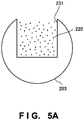
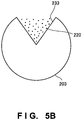
- Figs. 5A to 5D are sectional views for explaining the shape of the groove 231 of the powder replenisher 203.
- the sectional shape of the groove 231 may be any of rectangular, triangular, and semicircular shapes as long as it is possible to store a predetermined amount of powder.
- the groove 231 By forming the groove 231 to have a rectangular sectional shape shown in Fig. 5A , the groove 231 can have a large capacity to increase the processing amount and stored amount of the powder 220. Furthermore, the manufacturing cost of the powder replenisher 203 can be reduced.
- the powder 220 readily drops. For example, especially if the powder 220 is wet by containing moisture, the powder 220 is difficult to adhere to the inner surface of the groove 233. Furthermore, the strength of the powder replenisher 203 is relatively readily maintained. For example, as for the rectangular sectional shape described above, if the depth of the groove 233 is made too large, the powder replenisher 203 readily bends. However, if the sectional shape is a fan or triangular shape, it is possible to reduce the possibility of breakage.
- the groove 234 By forming the groove 234 to have a semicircular sectional shape shown in Fig. 5C , the groove 234 can keep a capacity to contain the powder 220. As in a case in which the groove 234 has a rectangular or triangular shape, it becomes easy to prevent the powder 220 from adhering to the corner of the groove 234 to remain in the groove 234.
- the number of grooves 231 formed in the powder replenisher 203 is not limited to one, and a plurality of grooves 231 may be formed.
- the powder 220 can be supplied from another groove 232 to the powder spreader 202. This is thus effective if it takes a long time to supply the powder 220 to the grooves 231. It is also possible to supply the powder 220 to the powder spreader 202 more quickly.
- the four grooves 231 are formed.
- the number of grooves 231 may be two, three, four, or more.
- the powder replenisher 203 may be caused to pivot or rotated in one direction, which can be set by the user, as needed, in accordance with an application purpose.
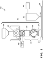
- FIG. 6 is a schematic front view for explaining the overall arrangement of the three-dimensional shaping apparatus according to this embodiment.
- a three-dimensional shaping apparatus 600 according to this embodiment is an apparatus using the powder supply apparatus according to the second embodiment. Therefore, the arrangement and operation of a powder supply apparatus in Fig. 6 are the same as those in the second embodiment, so the same reference numerals denote the same arrangement and operation and a detailed description thereof will be omitted.
- the three-dimensional shaping apparatus 600 includes a powder supply apparatus 200, a sprayer 601, and a supplier 602.
- the sprayer 601 sprays a binder 611 to a powder 220 spread on a shaping surface 210, and solidifies the powder 220.
- an irradiator for irradiating the powder 220 on the shaping surface 210 with a laser beam or electron beam may be provided instead of the sprayer 601, and can be selected, as needed, in accordance with the properties of the powder 220 or the type or application purpose of a shaped object 230.
- the supplier 602 supplies a binder or purge gas, but a supplied material is not limited to them, and a supplied material necessary for three-dimensional shaping can be supplied, as needed.
- Fig. 6 does not show other general-purpose devices and mechanisms of the three-dimensional shaping apparatus 600.
- Fig. 7 is a flowchart for explaining the control procedure of a powder spreader 202 of the three-dimensional shaping apparatus according to this embodiment.
- the three-dimensional shaping apparatus 600 determines whether an operation of shaping a three-dimensional shaped object is in progress. If the shaping operation is not in progress, the three-dimensional shaping apparatus 600 stands by until the shaping operation starts.
- the three-dimensional shaping apparatus 600 determines in step S703 whether an intermediate storage 222 and recoater 221 of the powder spreader 202 are empty. If the powder spreader 202 and the like are not empty, the three-dimensional shaping apparatus 600 stands by until the powder spreader 202 and the like become empty; otherwise, the three-dimensional shaping apparatus advances to the next step.
- step S705 the three-dimensional shaping apparatus 600 determines whether the powder spreader 202 is at a supply position. If the powder spreader 202 is not at the supply position, the three-dimensional shaping apparatus 600 stands by until the powder spreader 202 returns to the supply position; otherwise, the three-dimensional shaping apparatus 600 advances to the next step.
- step S707 the three-dimensional shaping apparatus 600 determines whether a powder replenisher 203 is full. If the powder replenisher 203 is not full, the three-dimensional shaping apparatus 600 stands by until the powder replenisher 203 becomes full; otherwise, the three-dimensional shaping apparatus 600 advances to the next step.
- step S709 the three-dimensional shaping apparatus 600 moves the powder replenisher 203 to replenish the powder spreader 202 with the powder 220.
- Fig. 8 is a flowchart for explaining the control procedure of the powder replenisher 203 of the three-dimensional shaping apparatus according to this embodiment.
- step S801 the three-dimensional shaping apparatus 600 determines whether an operation of shaping a three-dimensional shaped object is in progress. If the shaping operation is not in progress, the three-dimensional shaping apparatus 600 stands by until the shaping operation starts.
- the three-dimensional shaping apparatus 600 determines in step S803 whether the powder replenisher 203 is empty. If the powder replenisher 203 is not empty, the three-dimensional shaping apparatus 600 stands by until the powder replenisher 203 becomes empty.
- the three-dimensional shaping apparatus 600 supplies, in step S805, the powder 220 to the powder replenisher 203 from an intermediate hopper 205 or the like.
- step S807 the three-dimensional shaping apparatus 600 determines whether the powder spreader 202 is full. If the powder spreader 202 is full, the three-dimensional shaping apparatus 600 stands by until the powder spreader 202 becomes empty. If the powder spreader 202 is empty, the three-dimensional shaping apparatus 600 advances to the next step.
- step S809 the three-dimensional shaping apparatus 600 moves the powder replenisher 203 to replenish the powder spreader 202 with the powder 220.
- the recoater since it is possible to correctly and quickly measure a predetermined amount of powder, for example, an amount for one layer, and supply the predetermined amount of powder from the hopper to the recoater at high speed, the recoater need not wait for supply of the powder, and it is possible to correctly laminate a shaped object without wasting the material such as the powder. Furthermore, since the powder is not supplied using vibration, there is no mechanism of restricting the powder supply speed, thereby making it possible to supply the powder at high speed. Since there is no extra mechanism, the running cost and maintenance cost are reduced and the operating ratio of the three-dimensional shaping apparatus is improved without any failure of a machine or need of maintenance.
- the present invention is applicable to a system including a plurality of devices or a single apparatus.
- the present invention is also applicable even when an information processing program for implementing the functions of the embodiments is supplied to the system or apparatus directly or from a remote site.
- the present invention also incorporates the program installed in a computer to implement the functions of the present invention by the computer, a medium storing the program, and a WWW (World Wide Web) server that causes a user to download the program.
- the present invention incorporates at least a non-transitory computer readable medium storing a program that causes a computer to execute processing steps included in the above-described embodiments.
Landscapes
- Engineering & Computer Science (AREA)
- Mechanical Engineering (AREA)
- Chemical & Material Sciences (AREA)
- Materials Engineering (AREA)
- Physics & Mathematics (AREA)
- Optics & Photonics (AREA)
- Manufacturing & Machinery (AREA)
- Plasma & Fusion (AREA)
- Robotics (AREA)
- Automation & Control Theory (AREA)
- Powder Metallurgy (AREA)
Applications Claiming Priority (1)
| Application Number | Priority Date | Filing Date | Title |
|---|---|---|---|
| PCT/JP2015/059005 WO2016151783A1 (ja) | 2015-03-24 | 2015-03-24 | 粉末供給装置、粉末供給装置の制御方法、粉末供給装置の制御プログラムおよび3次元造形装置 |
Publications (3)
| Publication Number | Publication Date |
|---|---|
| EP3159145A1 true EP3159145A1 (de) | 2017-04-26 |
| EP3159145A4 EP3159145A4 (de) | 2018-04-11 |
| EP3159145B1 EP3159145B1 (de) | 2020-07-01 |
Family
ID=56977218
Family Applications (1)
| Application Number | Title | Priority Date | Filing Date |
|---|---|---|---|
| EP15886336.5A Active EP3159145B1 (de) | 2015-03-24 | 2015-03-24 | Pulverzuführungsvorrichtung, verfahren zur steuerung der pulverzuführungsvorrichtung und vorrichtung zur dreidimensionalen formung |
Country Status (4)
| Country | Link |
|---|---|
| US (1) | US10786870B2 (de) |
| EP (1) | EP3159145B1 (de) |
| JP (1) | JP6050550B1 (de) |
| WO (1) | WO2016151783A1 (de) |
Cited By (4)
| Publication number | Priority date | Publication date | Assignee | Title |
|---|---|---|---|---|
| CN108195181A (zh) * | 2017-12-29 | 2018-06-22 | 王传兰 | 中药饮片均布烘干设备及其使用方法 |
| WO2018222367A1 (en) * | 2017-05-31 | 2018-12-06 | General Electric Company | Apparatus and method for angular and rotational additive manufacturing |
| CN109177152A (zh) * | 2018-08-01 | 2019-01-11 | 大族激光科技产业集团股份有限公司 | 增材制造铺粉装置 |
| WO2019133099A1 (en) * | 2017-12-26 | 2019-07-04 | Desktop Metal, Inc. | System and method for controlling powder bed density for 3d printing |
Families Citing this family (35)
| Publication number | Priority date | Publication date | Assignee | Title |
|---|---|---|---|---|
| BG67063B1 (bg) * | 2015-04-09 | 2020-04-30 | „Принт Каст“ Оод | Метод и система за послойно изграждане на тримерни модели от прахообра зен материал |
| US10669071B2 (en) * | 2016-06-28 | 2020-06-02 | Delavan Inc | Powder container systems for additive manufacturing |
| DE202016006355U1 (de) | 2016-10-12 | 2018-01-15 | Realizer Gmbh | Anlage zur Objektherstellung aus Werkstoffpulver mit Bereitstellung des Pulvers in Linienform |
| WO2018090186A1 (zh) * | 2016-11-15 | 2018-05-24 | 东台精机股份有限公司 | 铺粉机的供粉装置 |
| US10022794B1 (en) * | 2017-01-13 | 2018-07-17 | General Electric Company | Additive manufacturing using a mobile build volume |
| US20180200962A1 (en) | 2017-01-13 | 2018-07-19 | General Electric Company | Additive manufacturing using a dynamically grown build envelope |
| US10478893B1 (en) | 2017-01-13 | 2019-11-19 | General Electric Company | Additive manufacturing using a selective recoater |
| JP6879802B2 (ja) * | 2017-03-31 | 2021-06-02 | ダイハツ工業株式会社 | 三次元積層造形装置 |
| WO2018216802A1 (ja) | 2017-05-26 | 2018-11-29 | 株式会社Ihi | 三次元積層造形物製造装置、三次元積層造形物製造方法及び探傷器 |
| BE1025291B1 (nl) * | 2017-06-06 | 2019-01-15 | Layerwise N.V. | Werkwijze en inrichting voor het doseren van een poeder voor het additief vervaardigen van een product |
| WO2018227229A1 (en) * | 2017-06-15 | 2018-12-20 | AmPro Innovations Pty Ltd | Improved additive manufacturing of metallic components |
| DE102017120205A1 (de) * | 2017-09-01 | 2019-03-07 | Exone Gmbh | Beschichteranordnung für einen 3d-drucker |
| JP6969612B2 (ja) | 2017-10-06 | 2021-11-24 | 株式会社Ihi | 粉末供給装置および三次元積層造形装置 |
| WO2019074955A1 (en) * | 2017-10-10 | 2019-04-18 | Applied Materials, Inc. | SELECTIVE POWDER DISPENSING FOR ADDITIVE MANUFACTURING |
| WO2019074107A1 (ja) * | 2017-10-13 | 2019-04-18 | 株式会社Ihi | 粉末供給装置および三次元積層造形装置 |
| US11612937B2 (en) | 2017-11-10 | 2023-03-28 | General Electric Company | Powder refill system for an additive manufacturing machine |
| CN108127909A (zh) * | 2017-12-19 | 2018-06-08 | 中国兵器装备研究院 | 一种定量上送粉装置 |
| US20210283846A1 (en) * | 2017-12-21 | 2021-09-16 | Hewlett-Packard Development Company, L.P. | Emptying vessels in a build device |
| GB2569649B (en) * | 2017-12-22 | 2020-06-10 | Reliance Prec Limited | Powder supply in additive layer manufacturing apparatus |
| CN111971162A (zh) * | 2018-03-30 | 2020-11-20 | Cmet公司 | 材料供给装置、材料供给装置的控制方法及材料供给装置的控制程序 |
| US11426818B2 (en) | 2018-08-10 | 2022-08-30 | The Research Foundation for the State University | Additive manufacturing processes and additively manufactured products |
| US11680379B2 (en) | 2019-02-15 | 2023-06-20 | Douglas Dynamics, L.L.C. | Spreader with shaftless auger |
| KR102078812B1 (ko) * | 2019-07-19 | 2020-02-19 | 주식회사 에스에프에스 | 분말 정량 도포 장치 및 이를 포함하는 3차원 프린터 |
| KR102084892B1 (ko) * | 2019-10-08 | 2020-05-26 | 주식회사 에스앤티 | 3d 프린터용 파우더 공급장치 및 그를 가지는 3d 프린터 |
| CN110624775B (zh) * | 2019-10-20 | 2025-01-03 | 内蒙古君诚兴业管道有限责任公司 | 一种淋涂量可变的淋涂粉末均匀撒料轴 |
| US11524455B2 (en) * | 2019-11-25 | 2022-12-13 | Applied Materials, Inc. | Removable unit for selective powder delivery for additive manufacturing |
| US11518097B2 (en) | 2019-11-25 | 2022-12-06 | Applied Materials, Inc. | Selective powder dispenser configurations for additive manufacturing |
| KR102252790B1 (ko) * | 2019-11-27 | 2021-05-17 | 한국생산기술연구원 | 소재 보충용 호퍼 장치 및 소재 적층 장치 |
| CN112157259B (zh) * | 2020-09-25 | 2022-07-05 | 大连交通大学 | 一种增减材激光加工用转盘式送粉装置 |
| KR102420421B1 (ko) * | 2021-02-16 | 2022-07-14 | 박소하 | 해머팁의 내마모 육성용접장치 및 용접방법 |
| CN114290667B (zh) * | 2021-12-29 | 2024-02-20 | 湖南华曙高科技股份有限公司 | 铺粉装置和3d打印机 |
| US12330857B1 (en) | 2025-01-29 | 2025-06-17 | Prince Mohammad Bin Fahd University | Coaxial multi-disc powder feeder system for multi powder flow and composition control |
| US12420245B1 (en) | 2025-04-24 | 2025-09-23 | Prince Mohammad Bin Fahd University | Method for powder flow control |
| US12391491B1 (en) | 2025-04-24 | 2025-08-19 | Prince Mohammad Bin Fahd University | Method and apparatis for transport of fine solids including powders |
| US12440812B1 (en) | 2025-04-24 | 2025-10-14 | Prince Mohammad Bin Fahd University | Multi powder mixing system |
Family Cites Families (20)
| Publication number | Priority date | Publication date | Assignee | Title |
|---|---|---|---|---|
| AT325005B (de) * | 1967-11-20 | 1975-09-25 | Benno Saladin | Verfahren und vorrichtung zum beschichten als endlose bahnen oder in formatzuschnitten auftretender unterlagen mit pulverförmigenwerkstoffen |
| US4205986A (en) * | 1977-06-24 | 1980-06-03 | American Can Company | Process for fabricating steel from ferrous metal particles |
| US4190440A (en) * | 1977-06-24 | 1980-02-26 | American Can Company | Process for fabricating steel from ferrous metal particles |
| US4349323A (en) * | 1981-01-30 | 1982-09-14 | Ray-O-Vac Corporation | Apparatus for continuously feeding powders |
| US5310582A (en) * | 1993-02-19 | 1994-05-10 | Board Of Trustees Operating Michigan State University | Apparatus and high speed method for coating elongated fibers |
| DE4400523C2 (de) * | 1994-01-11 | 1996-07-11 | Eos Electro Optical Syst | Verfahren und Vorrichtung zum Herstellen eines dreidimensionalen Objekts |
| US6183232B1 (en) * | 1996-12-18 | 2001-02-06 | Amsted Industries Incorporated | Raw material delivery system for compacting press |
| CA2227672A1 (en) * | 1997-01-29 | 1998-07-29 | Toyota Jidosha Kabushiki Kaisha | Method for producing a laminated object and apparatus for producing the same |
| JP3233339B2 (ja) * | 1997-01-29 | 2001-11-26 | トヨタ自動車株式会社 | 積層造形装置 |
| JP2001269935A (ja) * | 2000-03-24 | 2001-10-02 | Sumitomo Heavy Ind Ltd | 成形材料供給装置 |
| US6511631B2 (en) * | 2000-04-21 | 2003-01-28 | Sumitomo Special Metals Co., Ltd. | Powder compacting apparatus and method of producing a rare-earth magnet using the same |
| JP2002292748A (ja) | 2001-03-29 | 2002-10-09 | Minolta Co Ltd | 彩色三次元造形システム及び方法、彩色三次元造形用のデータ処理装置及び方法、彩色三次元造形用のデータ処理プログラム、並びに該データ処理プログラムを記録した記録媒体 |
| US20050280185A1 (en) * | 2004-04-02 | 2005-12-22 | Z Corporation | Methods and apparatus for 3D printing |
| US7713043B2 (en) * | 2005-10-20 | 2010-05-11 | Quantumsphere, Inc. | Apparatus for uniform feeding of powders |
| US8550802B2 (en) * | 2008-04-21 | 2013-10-08 | Panasonic Corporation | Stacked-layers forming device |
| GB0821660D0 (en) * | 2008-11-27 | 2008-12-31 | Univ Exeter The | Manufacturing device and method |
| DE102009056687B4 (de) * | 2009-12-02 | 2011-11-10 | Prometal Rct Gmbh | Anlage zum schichtweisen Aufbau eines Formkörpers mit einer Beschichter-Reinigungsvorrichtung |
| US8955558B2 (en) * | 2012-06-18 | 2015-02-17 | Stratasys, Inc. | Hopper valve for extrusion-based additive manufacturing systems, and methods of use thereof |
| JP6046534B2 (ja) * | 2013-03-26 | 2016-12-14 | 本田技研工業株式会社 | 粉体供給装置及びこの粉体供給装置を備えた三次元造形装置 |
| JP6077718B2 (ja) * | 2015-02-27 | 2017-02-08 | 技術研究組合次世代3D積層造形技術総合開発機構 | 粉末リコータ |
-
2015
- 2015-03-24 WO PCT/JP2015/059005 patent/WO2016151783A1/ja not_active Ceased
- 2015-03-24 EP EP15886336.5A patent/EP3159145B1/de active Active
- 2015-03-24 US US15/119,469 patent/US10786870B2/en active Active
- 2015-03-24 JP JP2016510855A patent/JP6050550B1/ja active Active
Cited By (5)
| Publication number | Priority date | Publication date | Assignee | Title |
|---|---|---|---|---|
| WO2018222367A1 (en) * | 2017-05-31 | 2018-12-06 | General Electric Company | Apparatus and method for angular and rotational additive manufacturing |
| WO2019133099A1 (en) * | 2017-12-26 | 2019-07-04 | Desktop Metal, Inc. | System and method for controlling powder bed density for 3d printing |
| US10940533B2 (en) | 2017-12-26 | 2021-03-09 | Desktop Metal, Inc. | System and method for controlling powder bed density for 3D printing |
| CN108195181A (zh) * | 2017-12-29 | 2018-06-22 | 王传兰 | 中药饮片均布烘干设备及其使用方法 |
| CN109177152A (zh) * | 2018-08-01 | 2019-01-11 | 大族激光科技产业集团股份有限公司 | 增材制造铺粉装置 |
Also Published As
| Publication number | Publication date |
|---|---|
| EP3159145B1 (de) | 2020-07-01 |
| US20170050270A1 (en) | 2017-02-23 |
| JP6050550B1 (ja) | 2016-12-21 |
| WO2016151783A1 (ja) | 2016-09-29 |
| JPWO2016151783A1 (ja) | 2017-04-27 |
| US10786870B2 (en) | 2020-09-29 |
| EP3159145A4 (de) | 2018-04-11 |
Similar Documents
| Publication | Publication Date | Title |
|---|---|---|
| EP3159145B1 (de) | Pulverzuführungsvorrichtung, verfahren zur steuerung der pulverzuführungsvorrichtung und vorrichtung zur dreidimensionalen formung | |
| KR101307509B1 (ko) | 분말 도포 장치 | |
| EP3085517B1 (de) | Pulverbeschichtungsvorrichtung | |
| US11780167B2 (en) | Apparatus for the manufacture of three-dimensional objects | |
| KR20200055142A (ko) | 적층 제조를 위한 선택적 분말 전달 | |
| EP3487683B1 (de) | Baumaterialpartikelschichtung | |
| US10828832B2 (en) | Powder dispensing unit, powder spreading unit, and a vibratory compaction system of an additive manufacturing system and methods therefor | |
| JP6828829B2 (ja) | 粉末供給装置および三次元積層造形装置 | |
| EP1486318B2 (de) | Verfahren und Vorrichtung zur Herstellung eines Formteils durch "Solid Freeform Fabrication" | |
| US20180126720A1 (en) | Part holder for additive manufacturing system | |
| EP3693103A1 (de) | Pulverzufuhrvorrichtung und dreidimensionale laminatmodellierungsvorrichtung | |
| EP3762216B1 (de) | Zuführen von material zu einer plattform der generativen fertigung | |
| JP2015182295A (ja) | 積層造形装置の材料供給装置、積層造形装置、及び積層造形方法 | |
| US10894360B2 (en) | Powder dispensing unit, powder spreading unit, and a vibratory compaction system of an additive manufacturing system and methods therefor | |
| JP7529475B2 (ja) | 粉体材料から物体を付加製造するための装置および方法 | |
| KR20170089625A (ko) | Sls 3d 프린터용 분말층 형성 장치 | |
| JP2018501997A (ja) | 粒子移送管を含む3次元成形物製造装置 | |
| CN112912200A (zh) | 数控装置、附加制造装置及附加制造装置的控制方法 | |
| US12594723B2 (en) | Powder distribution device and 3D printing device including same | |
| EP3867041B1 (de) | Systeme zur generativen fertigung | |
| EP4151391A1 (de) | Pbf-drucker mit einem pulverzirkulationssystem | |
| CN107430638A (zh) | 用于制造三维物体的设备以及所属的方法 | |
| JP2025003657A (ja) | 積層造形方法 | |
| Patil et al. | Powder feeding mechanisms in additive manufacturing: a review | |
| US10814555B2 (en) | Powder dispensing unit, powder spreading unit, and a vibratory compaction system of an additive manufacturing system and methods therefor |
Legal Events
| Date | Code | Title | Description |
|---|---|---|---|
| STAA | Information on the status of an ep patent application or granted ep patent |
Free format text: STATUS: THE INTERNATIONAL PUBLICATION HAS BEEN MADE |
|
| PUAI | Public reference made under article 153(3) epc to a published international application that has entered the european phase |
Free format text: ORIGINAL CODE: 0009012 |
|
| STAA | Information on the status of an ep patent application or granted ep patent |
Free format text: STATUS: REQUEST FOR EXAMINATION WAS MADE |
|
| 17P | Request for examination filed |
Effective date: 20170119 |
|
| AK | Designated contracting states |
Kind code of ref document: A1 Designated state(s): AL AT BE BG CH CY CZ DE DK EE ES FI FR GB GR HR HU IE IS IT LI LT LU LV MC MK MT NL NO PL PT RO RS SE SI SK SM TR |
|
| AX | Request for extension of the european patent |
Extension state: BA ME |
|
| A4 | Supplementary search report drawn up and despatched |
Effective date: 20180308 |
|
| RIC1 | Information provided on ipc code assigned before grant |
Ipc: B33Y 30/00 20150101ALI20180303BHEP Ipc: B22F 3/105 20060101ALI20180303BHEP Ipc: B65G 49/00 20060101ALI20180303BHEP Ipc: B65G 37/00 20060101ALI20180303BHEP Ipc: B65G 33/08 20060101ALI20180303BHEP Ipc: B65G 65/30 20060101ALI20180303BHEP Ipc: B05C 19/04 20060101ALI20180303BHEP Ipc: B65D 88/28 20060101ALI20180303BHEP Ipc: B29C 67/00 20170101AFI20180303BHEP |
|
| DAV | Request for validation of the european patent (deleted) | ||
| DAX | Request for extension of the european patent (deleted) | ||
| STAA | Information on the status of an ep patent application or granted ep patent |
Free format text: STATUS: EXAMINATION IS IN PROGRESS |
|
| 17Q | First examination report despatched |
Effective date: 20190503 |
|
| GRAP | Despatch of communication of intention to grant a patent |
Free format text: ORIGINAL CODE: EPIDOSNIGR1 |
|
| STAA | Information on the status of an ep patent application or granted ep patent |
Free format text: STATUS: GRANT OF PATENT IS INTENDED |
|
| INTG | Intention to grant announced |
Effective date: 20200117 |
|
| GRAS | Grant fee paid |
Free format text: ORIGINAL CODE: EPIDOSNIGR3 |
|
| GRAA | (expected) grant |
Free format text: ORIGINAL CODE: 0009210 |
|
| STAA | Information on the status of an ep patent application or granted ep patent |
Free format text: STATUS: THE PATENT HAS BEEN GRANTED |
|
| AK | Designated contracting states |
Kind code of ref document: B1 Designated state(s): AL AT BE BG CH CY CZ DE DK EE ES FI FR GB GR HR HU IE IS IT LI LT LU LV MC MK MT NL NO PL PT RO RS SE SI SK SM TR |
|
| REG | Reference to a national code |
Ref country code: CH Ref legal event code: EP Ref country code: AT Ref legal event code: REF Ref document number: 1285769 Country of ref document: AT Kind code of ref document: T Effective date: 20200715 |
|
| REG | Reference to a national code |
Ref country code: IE Ref legal event code: FG4D |
|
| REG | Reference to a national code |
Ref country code: DE Ref legal event code: R096 Ref document number: 602015055255 Country of ref document: DE |
|
| REG | Reference to a national code |
Ref country code: LT Ref legal event code: MG4D |
|
| PG25 | Lapsed in a contracting state [announced via postgrant information from national office to epo] |
Ref country code: BG Free format text: LAPSE BECAUSE OF FAILURE TO SUBMIT A TRANSLATION OF THE DESCRIPTION OR TO PAY THE FEE WITHIN THE PRESCRIBED TIME-LIMIT Effective date: 20201001 |
|
| REG | Reference to a national code |
Ref country code: NL Ref legal event code: MP Effective date: 20200701 |
|
| REG | Reference to a national code |
Ref country code: AT Ref legal event code: MK05 Ref document number: 1285769 Country of ref document: AT Kind code of ref document: T Effective date: 20200701 |
|
| PG25 | Lapsed in a contracting state [announced via postgrant information from national office to epo] |
Ref country code: ES Free format text: LAPSE BECAUSE OF FAILURE TO SUBMIT A TRANSLATION OF THE DESCRIPTION OR TO PAY THE FEE WITHIN THE PRESCRIBED TIME-LIMIT Effective date: 20200701 Ref country code: NO Free format text: LAPSE BECAUSE OF FAILURE TO SUBMIT A TRANSLATION OF THE DESCRIPTION OR TO PAY THE FEE WITHIN THE PRESCRIBED TIME-LIMIT Effective date: 20201001 Ref country code: SE Free format text: LAPSE BECAUSE OF FAILURE TO SUBMIT A TRANSLATION OF THE DESCRIPTION OR TO PAY THE FEE WITHIN THE PRESCRIBED TIME-LIMIT Effective date: 20200701 Ref country code: CZ Free format text: LAPSE BECAUSE OF FAILURE TO SUBMIT A TRANSLATION OF THE DESCRIPTION OR TO PAY THE FEE WITHIN THE PRESCRIBED TIME-LIMIT Effective date: 20200701 Ref country code: HR Free format text: LAPSE BECAUSE OF FAILURE TO SUBMIT A TRANSLATION OF THE DESCRIPTION OR TO PAY THE FEE WITHIN THE PRESCRIBED TIME-LIMIT Effective date: 20200701 Ref country code: PT Free format text: LAPSE BECAUSE OF FAILURE TO SUBMIT A TRANSLATION OF THE DESCRIPTION OR TO PAY THE FEE WITHIN THE PRESCRIBED TIME-LIMIT Effective date: 20201102 Ref country code: LT Free format text: LAPSE BECAUSE OF FAILURE TO SUBMIT A TRANSLATION OF THE DESCRIPTION OR TO PAY THE FEE WITHIN THE PRESCRIBED TIME-LIMIT Effective date: 20200701 Ref country code: FI Free format text: LAPSE BECAUSE OF FAILURE TO SUBMIT A TRANSLATION OF THE DESCRIPTION OR TO PAY THE FEE WITHIN THE PRESCRIBED TIME-LIMIT Effective date: 20200701 Ref country code: AT Free format text: LAPSE BECAUSE OF FAILURE TO SUBMIT A TRANSLATION OF THE DESCRIPTION OR TO PAY THE FEE WITHIN THE PRESCRIBED TIME-LIMIT Effective date: 20200701 Ref country code: GR Free format text: LAPSE BECAUSE OF FAILURE TO SUBMIT A TRANSLATION OF THE DESCRIPTION OR TO PAY THE FEE WITHIN THE PRESCRIBED TIME-LIMIT Effective date: 20201002 |
|
| PG25 | Lapsed in a contracting state [announced via postgrant information from national office to epo] |
Ref country code: RS Free format text: LAPSE BECAUSE OF FAILURE TO SUBMIT A TRANSLATION OF THE DESCRIPTION OR TO PAY THE FEE WITHIN THE PRESCRIBED TIME-LIMIT Effective date: 20200701 Ref country code: LV Free format text: LAPSE BECAUSE OF FAILURE TO SUBMIT A TRANSLATION OF THE DESCRIPTION OR TO PAY THE FEE WITHIN THE PRESCRIBED TIME-LIMIT Effective date: 20200701 Ref country code: PL Free format text: LAPSE BECAUSE OF FAILURE TO SUBMIT A TRANSLATION OF THE DESCRIPTION OR TO PAY THE FEE WITHIN THE PRESCRIBED TIME-LIMIT Effective date: 20200701 Ref country code: IS Free format text: LAPSE BECAUSE OF FAILURE TO SUBMIT A TRANSLATION OF THE DESCRIPTION OR TO PAY THE FEE WITHIN THE PRESCRIBED TIME-LIMIT Effective date: 20201101 |
|
| PG25 | Lapsed in a contracting state [announced via postgrant information from national office to epo] |
Ref country code: NL Free format text: LAPSE BECAUSE OF FAILURE TO SUBMIT A TRANSLATION OF THE DESCRIPTION OR TO PAY THE FEE WITHIN THE PRESCRIBED TIME-LIMIT Effective date: 20200701 |
|
| REG | Reference to a national code |
Ref country code: DE Ref legal event code: R097 Ref document number: 602015055255 Country of ref document: DE |
|
| PG25 | Lapsed in a contracting state [announced via postgrant information from national office to epo] |
Ref country code: IT Free format text: LAPSE BECAUSE OF FAILURE TO SUBMIT A TRANSLATION OF THE DESCRIPTION OR TO PAY THE FEE WITHIN THE PRESCRIBED TIME-LIMIT Effective date: 20200701 Ref country code: DK Free format text: LAPSE BECAUSE OF FAILURE TO SUBMIT A TRANSLATION OF THE DESCRIPTION OR TO PAY THE FEE WITHIN THE PRESCRIBED TIME-LIMIT Effective date: 20200701 Ref country code: EE Free format text: LAPSE BECAUSE OF FAILURE TO SUBMIT A TRANSLATION OF THE DESCRIPTION OR TO PAY THE FEE WITHIN THE PRESCRIBED TIME-LIMIT Effective date: 20200701 Ref country code: RO Free format text: LAPSE BECAUSE OF FAILURE TO SUBMIT A TRANSLATION OF THE DESCRIPTION OR TO PAY THE FEE WITHIN THE PRESCRIBED TIME-LIMIT Effective date: 20200701 Ref country code: SM Free format text: LAPSE BECAUSE OF FAILURE TO SUBMIT A TRANSLATION OF THE DESCRIPTION OR TO PAY THE FEE WITHIN THE PRESCRIBED TIME-LIMIT Effective date: 20200701 |
|
| PLBE | No opposition filed within time limit |
Free format text: ORIGINAL CODE: 0009261 |
|
| STAA | Information on the status of an ep patent application or granted ep patent |
Free format text: STATUS: NO OPPOSITION FILED WITHIN TIME LIMIT |
|
| PG25 | Lapsed in a contracting state [announced via postgrant information from national office to epo] |
Ref country code: AL Free format text: LAPSE BECAUSE OF FAILURE TO SUBMIT A TRANSLATION OF THE DESCRIPTION OR TO PAY THE FEE WITHIN THE PRESCRIBED TIME-LIMIT Effective date: 20200701 |
|
| 26N | No opposition filed |
Effective date: 20210406 |
|
| PG25 | Lapsed in a contracting state [announced via postgrant information from national office to epo] |
Ref country code: SK Free format text: LAPSE BECAUSE OF FAILURE TO SUBMIT A TRANSLATION OF THE DESCRIPTION OR TO PAY THE FEE WITHIN THE PRESCRIBED TIME-LIMIT Effective date: 20200701 |
|
| PG25 | Lapsed in a contracting state [announced via postgrant information from national office to epo] |
Ref country code: SI Free format text: LAPSE BECAUSE OF FAILURE TO SUBMIT A TRANSLATION OF THE DESCRIPTION OR TO PAY THE FEE WITHIN THE PRESCRIBED TIME-LIMIT Effective date: 20200701 |
|
| PG25 | Lapsed in a contracting state [announced via postgrant information from national office to epo] |
Ref country code: MC Free format text: LAPSE BECAUSE OF FAILURE TO SUBMIT A TRANSLATION OF THE DESCRIPTION OR TO PAY THE FEE WITHIN THE PRESCRIBED TIME-LIMIT Effective date: 20200701 |
|
| REG | Reference to a national code |
Ref country code: CH Ref legal event code: PL |
|
| GBPC | Gb: european patent ceased through non-payment of renewal fee |
Effective date: 20210324 |
|
| REG | Reference to a national code |
Ref country code: BE Ref legal event code: MM Effective date: 20210331 |
|
| PG25 | Lapsed in a contracting state [announced via postgrant information from national office to epo] |
Ref country code: CH Free format text: LAPSE BECAUSE OF NON-PAYMENT OF DUE FEES Effective date: 20210331 Ref country code: LI Free format text: LAPSE BECAUSE OF NON-PAYMENT OF DUE FEES Effective date: 20210331 Ref country code: LU Free format text: LAPSE BECAUSE OF NON-PAYMENT OF DUE FEES Effective date: 20210324 Ref country code: GB Free format text: LAPSE BECAUSE OF NON-PAYMENT OF DUE FEES Effective date: 20210324 Ref country code: FR Free format text: LAPSE BECAUSE OF NON-PAYMENT OF DUE FEES Effective date: 20210331 Ref country code: IE Free format text: LAPSE BECAUSE OF NON-PAYMENT OF DUE FEES Effective date: 20210324 |
|
| PG25 | Lapsed in a contracting state [announced via postgrant information from national office to epo] |
Ref country code: BE Free format text: LAPSE BECAUSE OF NON-PAYMENT OF DUE FEES Effective date: 20210331 |
|
| REG | Reference to a national code |
Ref country code: DE Ref legal event code: R081 Ref document number: 602015055255 Country of ref document: DE Owner name: CMET INC., YOKOHAMA-SHI, JP Free format text: FORMER OWNER: TECHNOLOGY RESEARCH ASSOCIATION FOR FUTURE ADDITIVE MANUFACTURING, TOKYO, JP |
|
| PG25 | Lapsed in a contracting state [announced via postgrant information from national office to epo] |
Ref country code: HU Free format text: LAPSE BECAUSE OF FAILURE TO SUBMIT A TRANSLATION OF THE DESCRIPTION OR TO PAY THE FEE WITHIN THE PRESCRIBED TIME-LIMIT; INVALID AB INITIO Effective date: 20150324 |
|
| PG25 | Lapsed in a contracting state [announced via postgrant information from national office to epo] |
Ref country code: CY Free format text: LAPSE BECAUSE OF FAILURE TO SUBMIT A TRANSLATION OF THE DESCRIPTION OR TO PAY THE FEE WITHIN THE PRESCRIBED TIME-LIMIT Effective date: 20200701 |
|
| PG25 | Lapsed in a contracting state [announced via postgrant information from national office to epo] |
Ref country code: MK Free format text: LAPSE BECAUSE OF FAILURE TO SUBMIT A TRANSLATION OF THE DESCRIPTION OR TO PAY THE FEE WITHIN THE PRESCRIBED TIME-LIMIT Effective date: 20200701 |
|
| PG25 | Lapsed in a contracting state [announced via postgrant information from national office to epo] |
Ref country code: TR Free format text: LAPSE BECAUSE OF FAILURE TO SUBMIT A TRANSLATION OF THE DESCRIPTION OR TO PAY THE FEE WITHIN THE PRESCRIBED TIME-LIMIT Effective date: 20200701 |
|
| PG25 | Lapsed in a contracting state [announced via postgrant information from national office to epo] |
Ref country code: MT Free format text: LAPSE BECAUSE OF FAILURE TO SUBMIT A TRANSLATION OF THE DESCRIPTION OR TO PAY THE FEE WITHIN THE PRESCRIBED TIME-LIMIT Effective date: 20200701 |
|
| PGFP | Annual fee paid to national office [announced via postgrant information from national office to epo] |
Ref country code: DE Payment date: 20260330 Year of fee payment: 12 |