EP3158284B1 - Vorrichtung und verfahren zur erwärmung und vermessung von transparenten zylinderförmigen artikeln - Google Patents
Vorrichtung und verfahren zur erwärmung und vermessung von transparenten zylinderförmigen artikeln Download PDFInfo
- Publication number
- EP3158284B1 EP3158284B1 EP14737122.3A EP14737122A EP3158284B1 EP 3158284 B1 EP3158284 B1 EP 3158284B1 EP 14737122 A EP14737122 A EP 14737122A EP 3158284 B1 EP3158284 B1 EP 3158284B1
- Authority
- EP
- European Patent Office
- Prior art keywords
- sided
- peaks
- cylindrical article
- image
- peak
- Prior art date
- Legal status (The legal status is an assumption and is not a legal conclusion. Google has not performed a legal analysis and makes no representation as to the accuracy of the status listed.)
- Active
Links
- 238000000034 method Methods 0.000 title claims description 47
- 238000010438 heat treatment Methods 0.000 title claims description 29
- 230000003287 optical effect Effects 0.000 claims description 52
- 238000001228 spectrum Methods 0.000 claims description 35
- 239000010410 layer Substances 0.000 claims description 31
- 239000013307 optical fiber Substances 0.000 claims description 22
- 239000000463 material Substances 0.000 claims description 20
- 238000004519 manufacturing process Methods 0.000 claims description 19
- 238000005253 cladding Methods 0.000 claims description 17
- 238000004458 analytical method Methods 0.000 claims description 16
- 238000005259 measurement Methods 0.000 claims description 15
- OKTJSMMVPCPJKN-UHFFFAOYSA-N Carbon Chemical compound [C] OKTJSMMVPCPJKN-UHFFFAOYSA-N 0.000 claims description 11
- 229910002804 graphite Inorganic materials 0.000 claims description 11
- 239000010439 graphite Substances 0.000 claims description 11
- 238000001514 detection method Methods 0.000 claims description 10
- 230000010354 integration Effects 0.000 claims description 10
- 238000005070 sampling Methods 0.000 claims description 8
- 238000004891 communication Methods 0.000 claims description 5
- 239000012792 core layer Substances 0.000 claims description 4
- 230000007547 defect Effects 0.000 claims description 3
- 230000007246 mechanism Effects 0.000 claims description 2
- 239000011162 core material Substances 0.000 description 39
- 239000011521 glass Substances 0.000 description 19
- 239000000835 fiber Substances 0.000 description 9
- 238000005229 chemical vapour deposition Methods 0.000 description 6
- 230000008569 process Effects 0.000 description 6
- 238000005516 engineering process Methods 0.000 description 5
- 239000004071 soot Substances 0.000 description 5
- 230000015572 biosynthetic process Effects 0.000 description 4
- 238000001816 cooling Methods 0.000 description 4
- 239000012530 fluid Substances 0.000 description 4
- 238000012681 fiber drawing Methods 0.000 description 3
- 230000001681 protective effect Effects 0.000 description 3
- 238000004017 vitrification Methods 0.000 description 3
- VYPSYNLAJGMNEJ-UHFFFAOYSA-N Silicium dioxide Chemical compound O=[Si]=O VYPSYNLAJGMNEJ-UHFFFAOYSA-N 0.000 description 2
- 238000004364 calculation method Methods 0.000 description 2
- 230000000295 complement effect Effects 0.000 description 2
- 238000000151 deposition Methods 0.000 description 2
- 238000011161 development Methods 0.000 description 2
- 238000012986 modification Methods 0.000 description 2
- 230000004048 modification Effects 0.000 description 2
- 238000012544 monitoring process Methods 0.000 description 2
- 230000010355 oscillation Effects 0.000 description 2
- 238000012545 processing Methods 0.000 description 2
- 239000004065 semiconductor Substances 0.000 description 2
- 239000007787 solid Substances 0.000 description 2
- 238000010183 spectrum analysis Methods 0.000 description 2
- 239000000758 substrate Substances 0.000 description 2
- 238000007740 vapor deposition Methods 0.000 description 2
- KRHYYFGTRYWZRS-UHFFFAOYSA-M Fluoride anion Chemical compound [F-] KRHYYFGTRYWZRS-UHFFFAOYSA-M 0.000 description 1
- 229910019142 PO4 Inorganic materials 0.000 description 1
- 241000276427 Poecilia reticulata Species 0.000 description 1
- 230000004075 alteration Effects 0.000 description 1
- 230000005540 biological transmission Effects 0.000 description 1
- 230000008859 change Effects 0.000 description 1
- 230000000052 comparative effect Effects 0.000 description 1
- 239000000112 cooling gas Substances 0.000 description 1
- 230000008021 deposition Effects 0.000 description 1
- 238000013461 design Methods 0.000 description 1
- 229920006240 drawn fiber Polymers 0.000 description 1
- 238000003708 edge detection Methods 0.000 description 1
- 230000000694 effects Effects 0.000 description 1
- 230000005611 electricity Effects 0.000 description 1
- 230000003760 hair shine Effects 0.000 description 1
- 239000001307 helium Substances 0.000 description 1
- 229910052734 helium Inorganic materials 0.000 description 1
- SWQJXJOGLNCZEY-UHFFFAOYSA-N helium atom Chemical compound [He] SWQJXJOGLNCZEY-UHFFFAOYSA-N 0.000 description 1
- 238000005286 illumination Methods 0.000 description 1
- 238000003780 insertion Methods 0.000 description 1
- 230000037431 insertion Effects 0.000 description 1
- 239000012768 molten material Substances 0.000 description 1
- 230000007935 neutral effect Effects 0.000 description 1
- 238000000424 optical density measurement Methods 0.000 description 1
- 235000021317 phosphate Nutrition 0.000 description 1
- 150000003013 phosphoric acid derivatives Chemical class 0.000 description 1
- 239000004033 plastic Substances 0.000 description 1
- 229920003023 plastic Polymers 0.000 description 1
- 238000004886 process control Methods 0.000 description 1
- 230000005855 radiation Effects 0.000 description 1
- 238000010187 selection method Methods 0.000 description 1
- 239000000377 silicon dioxide Substances 0.000 description 1
- 238000007711 solidification Methods 0.000 description 1
- 230000008023 solidification Effects 0.000 description 1
- 238000012546 transfer Methods 0.000 description 1
- 238000012795 verification Methods 0.000 description 1
- 238000011179 visual inspection Methods 0.000 description 1
Images


Classifications
-
- G—PHYSICS
- G01—MEASURING; TESTING
- G01B—MEASURING LENGTH, THICKNESS OR SIMILAR LINEAR DIMENSIONS; MEASURING ANGLES; MEASURING AREAS; MEASURING IRREGULARITIES OF SURFACES OR CONTOURS
- G01B11/00—Measuring arrangements characterised by the use of optical techniques
- G01B11/08—Measuring arrangements characterised by the use of optical techniques for measuring diameters
- G01B11/12—Measuring arrangements characterised by the use of optical techniques for measuring diameters internal diameters
-
- G—PHYSICS
- G01—MEASURING; TESTING
- G01B—MEASURING LENGTH, THICKNESS OR SIMILAR LINEAR DIMENSIONS; MEASURING ANGLES; MEASURING AREAS; MEASURING IRREGULARITIES OF SURFACES OR CONTOURS
- G01B11/00—Measuring arrangements characterised by the use of optical techniques
- G01B11/08—Measuring arrangements characterised by the use of optical techniques for measuring diameters
-
- G—PHYSICS
- G06—COMPUTING; CALCULATING OR COUNTING
- G06T—IMAGE DATA PROCESSING OR GENERATION, IN GENERAL
- G06T7/00—Image analysis
- G06T7/60—Analysis of geometric attributes
- G06T7/62—Analysis of geometric attributes of area, perimeter, diameter or volume
-
- C—CHEMISTRY; METALLURGY
- C03—GLASS; MINERAL OR SLAG WOOL
- C03B—MANUFACTURE, SHAPING, OR SUPPLEMENTARY PROCESSES
- C03B37/00—Manufacture or treatment of flakes, fibres, or filaments from softened glass, minerals, or slags
- C03B37/01—Manufacture of glass fibres or filaments
- C03B37/02—Manufacture of glass fibres or filaments by drawing or extruding, e.g. direct drawing of molten glass from nozzles; Cooling fins therefor
-
- G—PHYSICS
- G01—MEASURING; TESTING
- G01B—MEASURING LENGTH, THICKNESS OR SIMILAR LINEAR DIMENSIONS; MEASURING ANGLES; MEASURING AREAS; MEASURING IRREGULARITIES OF SURFACES OR CONTOURS
- G01B5/00—Measuring arrangements characterised by the use of mechanical techniques
- G01B5/003—Measuring of motor parts
-
- G—PHYSICS
- G01—MEASURING; TESTING
- G01N—INVESTIGATING OR ANALYSING MATERIALS BY DETERMINING THEIR CHEMICAL OR PHYSICAL PROPERTIES
- G01N21/00—Investigating or analysing materials by the use of optical means, i.e. using sub-millimetre waves, infrared, visible or ultraviolet light
- G01N21/84—Systems specially adapted for particular applications
- G01N21/88—Investigating the presence of flaws or contamination
- G01N21/89—Investigating the presence of flaws or contamination in moving material, e.g. running paper or textiles
- G01N21/892—Investigating the presence of flaws or contamination in moving material, e.g. running paper or textiles characterised by the flaw, defect or object feature examined
- G01N21/896—Optical defects in or on transparent materials, e.g. distortion, surface flaws in conveyed flat sheet or rod
-
- G—PHYSICS
- G01—MEASURING; TESTING
- G01N—INVESTIGATING OR ANALYSING MATERIALS BY DETERMINING THEIR CHEMICAL OR PHYSICAL PROPERTIES
- G01N21/00—Investigating or analysing materials by the use of optical means, i.e. using sub-millimetre waves, infrared, visible or ultraviolet light
- G01N21/84—Systems specially adapted for particular applications
- G01N21/88—Investigating the presence of flaws or contamination
- G01N21/95—Investigating the presence of flaws or contamination characterised by the material or shape of the object to be examined
- G01N21/952—Inspecting the exterior surface of cylindrical bodies or wires
-
- G—PHYSICS
- G01—MEASURING; TESTING
- G01N—INVESTIGATING OR ANALYSING MATERIALS BY DETERMINING THEIR CHEMICAL OR PHYSICAL PROPERTIES
- G01N21/00—Investigating or analysing materials by the use of optical means, i.e. using sub-millimetre waves, infrared, visible or ultraviolet light
- G01N21/84—Systems specially adapted for particular applications
- G01N21/88—Investigating the presence of flaws or contamination
- G01N21/95—Investigating the presence of flaws or contamination characterised by the material or shape of the object to be examined
- G01N21/954—Inspecting the inner surface of hollow bodies, e.g. bores
-
- G—PHYSICS
- G01—MEASURING; TESTING
- G01N—INVESTIGATING OR ANALYSING MATERIALS BY DETERMINING THEIR CHEMICAL OR PHYSICAL PROPERTIES
- G01N21/00—Investigating or analysing materials by the use of optical means, i.e. using sub-millimetre waves, infrared, visible or ultraviolet light
- G01N21/84—Systems specially adapted for particular applications
- G01N21/88—Investigating the presence of flaws or contamination
- G01N21/95—Investigating the presence of flaws or contamination characterised by the material or shape of the object to be examined
- G01N21/958—Inspecting transparent materials or objects, e.g. windscreens
-
- G—PHYSICS
- G02—OPTICS
- G02B—OPTICAL ELEMENTS, SYSTEMS OR APPARATUS
- G02B23/00—Telescopes, e.g. binoculars; Periscopes; Instruments for viewing the inside of hollow bodies; Viewfinders; Optical aiming or sighting devices
- G02B23/24—Instruments or systems for viewing the inside of hollow bodies, e.g. fibrescopes
- G02B23/2407—Optical details
-
- G—PHYSICS
- G06—COMPUTING; CALCULATING OR COUNTING
- G06T—IMAGE DATA PROCESSING OR GENERATION, IN GENERAL
- G06T7/00—Image analysis
- G06T7/0002—Inspection of images, e.g. flaw detection
- G06T7/0004—Industrial image inspection
-
- G—PHYSICS
- G06—COMPUTING; CALCULATING OR COUNTING
- G06T—IMAGE DATA PROCESSING OR GENERATION, IN GENERAL
- G06T7/00—Image analysis
- G06T7/10—Segmentation; Edge detection
- G06T7/136—Segmentation; Edge detection involving thresholding
-
- G—PHYSICS
- G06—COMPUTING; CALCULATING OR COUNTING
- G06T—IMAGE DATA PROCESSING OR GENERATION, IN GENERAL
- G06T7/00—Image analysis
- G06T7/10—Segmentation; Edge detection
- G06T7/194—Segmentation; Edge detection involving foreground-background segmentation
-
- G—PHYSICS
- G01—MEASURING; TESTING
- G01M—TESTING STATIC OR DYNAMIC BALANCE OF MACHINES OR STRUCTURES; TESTING OF STRUCTURES OR APPARATUS, NOT OTHERWISE PROVIDED FOR
- G01M11/00—Testing of optical apparatus; Testing structures by optical methods not otherwise provided for
- G01M11/30—Testing of optical devices, constituted by fibre optics or optical waveguides
- G01M11/37—Testing of optical devices, constituted by fibre optics or optical waveguides in which light is projected perpendicularly to the axis of the fibre or waveguide for monitoring a section thereof
-
- H—ELECTRICITY
- H04—ELECTRIC COMMUNICATION TECHNIQUE
- H04N—PICTORIAL COMMUNICATION, e.g. TELEVISION
- H04N23/00—Cameras or camera modules comprising electronic image sensors; Control thereof
- H04N23/50—Constructional details
- H04N23/555—Constructional details for picking-up images in sites, inaccessible due to their dimensions or hazardous conditions, e.g. endoscopes or borescopes
Landscapes
- Physics & Mathematics (AREA)
- General Physics & Mathematics (AREA)
- Engineering & Computer Science (AREA)
- Chemical & Material Sciences (AREA)
- Life Sciences & Earth Sciences (AREA)
- Analytical Chemistry (AREA)
- Pathology (AREA)
- Immunology (AREA)
- Health & Medical Sciences (AREA)
- Biochemistry (AREA)
- General Health & Medical Sciences (AREA)
- Computer Vision & Pattern Recognition (AREA)
- Theoretical Computer Science (AREA)
- Textile Engineering (AREA)
- Optics & Photonics (AREA)
- Quality & Reliability (AREA)
- Geometry (AREA)
- Astronomy & Astrophysics (AREA)
- General Life Sciences & Earth Sciences (AREA)
- Geochemistry & Mineralogy (AREA)
- Manufacturing & Machinery (AREA)
- Materials Engineering (AREA)
- Organic Chemistry (AREA)
- Length Measuring Devices By Optical Means (AREA)
Claims (13)
- Vorrichtung zur Erwärmung eines transparenten zylinderförmigen Artikels (10) und zur Vermessung während seiner Herstellung, wobei die Vorrichtung umfasst:(A) einen Hochtemperaturofen (35; 49; 45; 55, 65), umfassend einen oberen Graphitkontakt (50) und einen unteren Graphitkontakt (60), wobei sowohl der obere als auch der untere Kontakt (50; 60) eine ringförmige Wand (55; 65) aufweisen und die Kontakte Teil des Heizmechanismus des Ofens sind; und einen beheizten Innenraum, der zwischen dem oberen und dem unteren Kontakt (50; 60) angeordnet ist, wobei die ringförmige Wand (65) des unteren Kontakts (60) eine seitliche Öffnung (67; 70) aufweist, die mit dem beheizten Innenraum (45) in Verbindung steht und durch die der zylinderförmige Artikel (10) sichtbar ist;(B) eine Digitalkamera (100) mit einer daran befestigten Linse (105) und einer Erfassungsund digitalen Aufzeichnungsvorrichtung, wobei die Linse (105) ein optisches Bild (115) des zylinderförmigen Artikels (10) durch die Öffnung (67; 70) der unteren ringförmigen Wand (65) empfängt und das optische Bild (115) auf die Erfassungs- und digitale Aufzeichnungsvorrichtung richtet, die das optische Bild (115) in ein digitales Bild umwandelt und das digitale Bild aufzeichnet, wobei die Kamera (100) von einem flüssigkeitsdichten, flüssigkeitsgekühlten Gehäuse (75) umschlossen ist, das eine mit der Öffnung (67; 70) der Ofenwand ausgerichtete Durchgangsöffnung (80) für den Durchgang des optischen Bildes des zylinderförmigen Artikels (10) aufweist; und(C) einen digitalen Prozessor, der mit einem Algorithmus programmiert ist, der auf das digitale Bild von der Erfassungs- und digitalen Aufzeichnungsvorrichtung zugreift und es auswertet und eine Messung des zylinderförmigen Artikels (10) bestimmt und meldet.
- Vorrichtung nach Anspruch 1, wobei der transparente zylinderförmige Artikel eine optische Faservorform (10) ist, die zwei oder mehr Schichten aus glasartigem Material umfasst, und wobei die Vorform (10) eine Kernschicht (15) mit einem Brechungsindex und eine Umhüllungsschicht (20) mit einem Brechungsindex aufweist und die innere Schicht (15) umgibt; wobei der Brechungsindex der Kernschicht (15) größer ist als der Brechungsindex der Umhüllungsschicht (20).
- Vorrichtung nach Anspruch 1, wobei die Erfassungs- und digitale Aufzeichnungsvorrichtung einen ladungsgekoppelten Vorrichtungsbildsensor ("CCD"-Bildsensor) umfasst,
wobei die Vorrichtung vorzugsweise ferner einen Reflektor (110) umfasst, um das durch die Öffnung (67; 70) der Ofenwand (65) und die Durchgangsöffnung des flüssigkeitsgekühlten Gehäuses (75) empfangene optische Bild auf die Linse (105) der Kamera (100) zu richten. - Vorrichtung nach Anspruch 1, wobei der Ofen ein ummantelter, flüssigkeitsgekühlter Graphitofen (35; 49; 45; 55, 65) ist, wobei der obere und der untere Kontakt (50; 60) annähernd gegenüberliegende Enden des beheizten Innenraums (45) sind und wobei der obere (50) und der untere Kontakt (60) elektrischen Strom aufnehmen und durch sie hindurchleiten, um den Innenraum des Graphitofens (35; 49; 45; 55, 65) mit dem darin befindlichen zylinderförmigen Artikel (10) zu erhitzen.
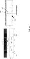
- Verfahren zum Messen des Durchmessers eines transparenten zylinderförmigen Artikels (10) während seiner Herstellung in einem Hochtemperaturofen (35; 49; 45; 55, 65) mit einer seitlichen Öffnung (67, 70), durch die der zylinderförmige Artikel (10) sichtbar ist, wobei das Verfahren umfasst:(A) Empfangen eines optischen Bildes des zylinderförmigen Artikels (10), das durch die seitliche Öffnung (67; 70) unter Verwendung einer Kamera (100) mit einer daran befestigten Linse (105) ausgegeben wird;(B) Richten des optischen Bildes auf eine Erfassungs- und digitale Aufzeichnungsvorrichtung;(C) Umwandeln des optischen Bildes in ein digitales Bild und Aufzeichnen des digitalen Bildes unter Verwendung der Erfassungs- und digitalen Aufzeichnungsvorrichtung; und(D) Auswerten des digitalen Bildes und Bestimmen des Durchmessers des zylinderförmigen Artikels unter Verwendung eines Prozessors, der mit einem Algorithmus programmiert ist, wobei der Algorithmus die folgenden Schritte umfasst:(1) Zuschneiden des digitalen Bildes, um den umgebenden dunklen Raum zu entfernen und ein kleineres zugeschnittenes digitales Bild zu erzeugen, das nur ein helles Sichtfeld einschließt, das durch die seitliche Öffnung des Ofens (35; 49; 45; 55, 65) sichtbar war, wobei das zugeschnittene digitale Bild eine Höhe und eine Breite aufweist;(2) Erzeugen eines gradientengefilterten Bildes aus dem zugeschnittenen digitalen Bild unter Verwendung eines Standardabweichungsfilters;(3) Durchführen mehrerer Zeilenabtastungen und Aufsummieren derselben, um ein Grauwertgradientenspektrum zu bilden, das eine oder mehrere linksseitige Spitzen (145), eine oder mehrere rechtsseitige Spitzen (150) und eine oder mehrere kleinere Hintergrundspitzen (155a; 155b; 155c) aufweist, wobei die Vielzahl von Gradientenlinien innerhalb eines Abtastbereichs abgetastet wird, der sich in der Nähe einer vertikalen Mitte des gradientengefilterten Bildes befindet und sich horizontal über die gesamte Breite des gradientengefilterten Bildes erstreckt;(4) Identifizieren, welche der einen oder mehreren linksseitigen Spitzen (145) und der einen oder mehreren rechtsseitigen Spitzen (150) im Grauwertgradientenspektrum tatsächliche linksseitige und rechtsseitige Kanten des zylinderförmigen Artikels (10) darstellen, durch Ausführen der nachstehenden Schritte:(a) auf dem Grauwertgradientenspektrum Auswählen eines linksseitigen Spitzen-Fensterbereichs (160), der die Vielzahl von linksseitigen Spitzen (145) beinhaltet, und Auswählen eines rechtsseitigen Spitzen-Fensterbereichs (165), der die Vielzahl von rechtsseitigen Spitzen (150) beinhaltet, wobei die kleineren Hintergrundspitzen (155a; 155b; 155c) außerhalb jedes Fensterbereichs (160; 165) für eine separate Analyse belassen werden;(b) Festlegen einer Bezugslinie für die Spitzenerfassung, welche die kleineren Hintergrundspitzen (155a; 155b; 155c) von der weiteren Analyse durch Folgendes ausschließt:(i) dynamisches Abtasten eines Abschnitts der kleineren Hintergrundspitzen (155a; 155b; 155c) und Berechnen eines Grundrauschpegels basierend auf der dynamischen Abtastung;(ii) Bestimmen einer Bezugslinie durch Hinzufügen eines Schwellenwerts zum Grundrauschpegel;(iii) danach Ignorieren aller Spitzen unterhalb der Bezugslinie;(c) Identifizieren einer linksseitigen Zielspitze (145) und einer rechtsseitigen Zielspitze (150), um numerische Werte für die Positionen der tatsächlichen linksseitigen bzw. rechtsseitigen Kanten des zylinderförmigen Artikels (10) bereitzustellen, durch:(i) Analysieren jeder der Vielzahl von linksseitigen Spitzen (145), die höher sind als die Bezugslinie in dem linksseitigen Spitzen-Fensterbereich (160), Auswählen der linksseitigen Zielspitze (145), die am weitesten links in dem linksseitigen Spitzen-Fensterbereich (160) positioniert ist, und Aufzeichnen ihrer Position als einen numerischen Wert, der gleich der tatsächlichen linksseitigen Kante des zylinderförmigen Artikels (10) ist;(ii) Analysieren jeder der Vielzahl von rechtsseitigen Spitzen (150), die höher sind als die Bezugslinie in dem rechtsseitigen Spitzen-Fensterbereich (165), Auswählen der rechtsseitigen Zielspitze (150), die am weitesten rechts in dem rechtsseitigen Spitzen-Fensterbereich (165) positioniert ist, und Aufzeichnen ihrer Position als einen numerischen Wert, der gleich der tatsächlichen rechtsseitigen Kante des zylinderförmigen Artikels (10) ist;(5) Berechnen des Außendurchmessers des zylinderförmigen Artikels (10) durch Ermitteln des absoluten Wertes der Differenz zwischen den Werten der tatsächlichen linksseitigen und rechtsseitigen Kante des zylinderförmigen Artikels (10); und(6) Melden des Außendurchmessers des zylinderförmigen Artikels (10).
- Verfahren nach Anspruch 5, wobei die Erfassungs- und digitale Aufzeichnungsvorrichtung in der Digitalkamera (100) untergebracht ist und
wobei die Erfassungs- und digitale Aufzeichnungsvorrichtung ein ladungsgekoppelter Vorrichtungsbildsensor ("CCD"-Bildsensor) ist. - Verfahren nach Anspruch 5, wobei die seitliche Öffnung (67; 70) des Ofens (35; 49; 45; 55, 65) eine Breite aufweist, die kleiner als der Durchmesser des zylinderförmigen Artikels (10) ist, und
wobei der Schritt (B) des Richtens des optischen Bildes ferner unter Verwendung eines Reflektors (110) durchgeführt wird. - Verfahren nach Anspruch 5, wobei ferner zu Schritt (3) jede Gradientenlinienabtastung durch Einstellen einer horizontalen Abtastlinienposition innerhalb des Abtastbereichs des gradientengefilterten Bildes und Erfassen und Aufzeichnen des Grauwerts des Bildes entlang der eingestellten horizontalen Abtastlinienposition durchgeführt wird, und wobei ferner zu Schritt (3) die Vielzahl von Gradientenlinienabtastungen insgesamt 40 bis 50 Abtastungen beträgt, und
wobei ferner zu Schritt (4)(a) der linksseitige Spitzen-Fensterbereich (160) auf einen höchsten der Vielzahl von linksseitigen Spitzen (145) zentriert ist und der rechtsseitige Spitzen-Fensterbereich (165) auf einen höchsten der Vielzahl von rechtsseitigen Spitzen (150) zentriert ist. - Verfahren nach Anspruch 8, wobei ferner zu Schritt (4)(b)(ii) der Schwellenwert gleich (einer maximalen Spitzenhöhe des Grauwertgradientenspektrums)-(dem Grundrauschpegel)/(einem vorbestimmten Faktor) ist, und
wobei nach Ausführen von Schritt (1), der das digitale Bild zuschneidet, um ein zugeschnittenes digitales Bild zu erzeugen, das Verfahren ferner das Berechnen des durchschnittlichen Grauwerts in dem zugeschnittenen digitalen Bild und, wenn der durchschnittliche Grauwert unter einem vorbestimmten Schwellenwert liegt, das Beenden des laufenden Algorithmus umfasst. - Verfahren nach Anspruch 8, wobei der Schwellenwert durch Berechnen des 0,5-fachen der durchschnittlichen Höhe des Abschnitts der dynamisch abgetasteten kleineren Hintergrundspitzen (155a; 155b; 155c) bestimmt wird.
- Verfahren nach Anspruch 5, ferner umfassend das Bestimmen einer Mittelposition des transparenten zylinderförmigen Artikels (10) durch Hinzufügen einer Hälfte des Außendurchmessers zum Wert der linksseitigen Kante.
- Verfahren zum Erfassen einer Verbindungsstelle oder eines Fehlers innerhalb eines transparenten zylinderförmigen Artikels (10) während seiner Herstellung in einem Hochtemperaturofen (35; 49; 45; 55, 65) mit einer seitlichen Öffnung (67; 70), durch die der zylinderförmige Artikel (10) sichtbar ist, wobei das Verfahren umfasst:(A) Empfangen eines optischen Bildes des zylinderförmigen Artikels (10), das durch die seitliche Öffnung (67; 70) unter Verwendung einer Kamera (100) mit einer daran befestigten Linse (105) ausgegeben wird;(B) Richten des optischen Bildes auf eine Erfassungs- und digitale Aufzeichnungsvorrichtung;(C) Umwandeln des optischen Bildes in ein digitales Bild und Aufzeichnen des digitalen Bildes unter Verwendung der Erfassungs- und digitalen Aufzeichnungsvorrichtung; und(D) Auswerten des digitalen Bildes und Bestimmen des Vorhandenseins einer Verbindungsstelle oder eines Fehlers innerhalb des zylinderförmigen Artikels unter Verwendung eines Prozessors, der mit einem Algorithmus programmiert ist, wobei der Algorithmus die folgenden Schritte umfasst:(1) Zuschneiden des digitalen Bildes, um den umgebenden dunklen Raum zu entfernen und ein kleineres zugeschnittenes digitales Bild zu erzeugen, das nur ein helles Sichtfeld einschließt, das durch die seitliche Öffnung des Ofens (35; 49; 45; 55, 65) sichtbar war, wobei das zugeschnittene digitale Bild eine Höhe und eine Breite aufweist;(2) Erzeugen eines gradientengefilterten Bildes aus dem zugeschnittenen digitalen Bild unter Verwendung eines Standardabweichungsfilters;(3) Durchführen mehrerer Zeilenabtastungen und Aufsummieren derselben, um ein Grauwertgradientenspektrum zu bilden, das eine oder mehrere linksseitige Spitzen (145), eine oder mehrere rechtsseitige Spitzen (150) und eine oder mehrere kleinere Hintergrundspitzen (155a; 155b; 155c) aufweist, wobei die Vielzahl von Gradientenlinien innerhalb eines Abtastbereichs abgetastet wird, der sich in der Nähe einer vertikalen Mitte des gradientengefilterten Bildes befindet und sich horizontal über die gesamte Breite des gradientengefilterten Bildes erstreckt;(4) Identifizieren, welche der einen oder mehreren linksseitigen Spitzen (145) und der einen oder mehreren rechtsseitigen Spitzen (150) im Grauwertgradientenspektrum tatsächliche linksseitige und rechtsseitige Kanten des zylinderförmigen Artikels (10) darstellen, durch Ausführen der nachstehenden Schritte:(a) auf dem Grauwertgradientenspektrum Auswählen eines linksseitigen Spitzen-Fensterbereichs (160), der die Vielzahl von linksseitigen Spitzen (145) beinhaltet, und Auswählen eines rechtsseitigen Spitzen-Fensterbereichs (165), der die Vielzahl von rechtsseitigen Spitzen (150) beinhaltet, wobei die kleineren Hintergrundspitzen (155a; 155b; 155c) außerhalb jedes Fensterbereichs (160; 165) für eine separate Analyse belassen werden;(b) Festlegen einer Bezugslinie für die Spitzenerfassung, welche die kleineren Hintergrundspitzen (155a; 155b; 155c) von der weiteren Analyse durch Folgendes ausschließt:(i) dynamisches Abtasten eines Abschnitts der kleineren Hintergrundspitzen (155a; 155b; 155c) und Berechnen eines Grundrauschpegels basierend auf der dynamischen Abtastung;(ii) Bestimmen einer Bezugslinie durch Hinzufügen eines Schwellenwerts zum Grundrauschpegel;(iii) danach Ignorieren aller Spitzen unterhalb der Bezugslinie;(c) Identifizieren einer linksseitigen Zielspitze (145) und einer rechtsseitigen Zielspitze (150), um numerische Werte für die Positionen der tatsächlichen linksseitigen bzw. rechtsseitigen Kanten des zylinderförmigen Artikels (10) bereitzustellen, durch:(i) Analysieren jeder der Vielzahl von linksseitigen Spitzen (145), die höher sind als die Bezugslinie in dem linksseitigen Spitzen-Fensterbereich (160), Auswählen der linksseitigen Zielspitze (145), die am weitesten links in dem linksseitigen Spitzen-Fensterbereich (160) positioniert ist, und Aufzeichnen ihrer Position als einen numerischen Wert, der gleich der tatsächlichen linksseitigen Kante des zylinderförmigen Artikels (10) ist;(ii) Analysieren jeder der Vielzahl von rechtsseitigen Spitzen (150), die höher sind als die Bezugslinie in dem rechtsseitigen Spitzen-Fensterbereich (165), Auswählen der rechtsseitigen Zielspitze (150), die am weitesten rechts in dem rechtsseitigen Spitzen-Fensterbereich (165) positioniert ist, und Aufzeichnen ihrer Position als einen numerischen Wert, der gleich der tatsächlichen rechtsseitigen Kante des zylinderförmigen Artikels (10) ist; und(5) Bestimmen, ob eine oder mehrere Zwischenspitzen (185) zwischen der tatsächlichen linksseitigen Spitze (145) und der tatsächlichen rechtsseitigen Spitze (150) vorhanden ist/sind.
- Verfahren nach Anspruch 12, wobei das Bestimmen, ob eine oder mehrere Zwischenspitzen (185) zwischen der tatsächlichen linksseitigen Spitze (145) und der tatsächlichen rechtsseitigen Spitze (150) vorhanden ist/sind, umfasst:(1) Auswählen eines zentralen Fensters (190) des Grauwertgradientenspektrums zwischen der tatsächlichen linksseitigen Spitze (145) und der tatsächlichen rechtsseitigen Spitze (150);(2) Berechnen eines Integrationsbereichs für das zentrale Fenster (190); und(3) Bestimmen, ob der Integrationsbereich einen vorbestimmten Wert überschreitet.
Applications Claiming Priority (1)
| Application Number | Priority Date | Filing Date | Title |
|---|---|---|---|
| PCT/US2014/042790 WO2015195102A1 (en) | 2014-06-17 | 2014-06-17 | Apparatus and method for measurement of transparent cylindrical articles |
Publications (2)
| Publication Number | Publication Date |
|---|---|
| EP3158284A1 EP3158284A1 (de) | 2017-04-26 |
| EP3158284B1 true EP3158284B1 (de) | 2022-03-16 |
Family
ID=51162961
Family Applications (1)
| Application Number | Title | Priority Date | Filing Date |
|---|---|---|---|
| EP14737122.3A Active EP3158284B1 (de) | 2014-06-17 | 2014-06-17 | Vorrichtung und verfahren zur erwärmung und vermessung von transparenten zylinderförmigen artikeln |
Country Status (6)
| Country | Link |
|---|---|
| US (1) | US10388028B2 (de) |
| EP (1) | EP3158284B1 (de) |
| JP (1) | JP6385472B2 (de) |
| KR (1) | KR102233643B1 (de) |
| CN (1) | CN107076544B (de) |
| WO (1) | WO2015195102A1 (de) |
Families Citing this family (6)
| Publication number | Priority date | Publication date | Assignee | Title |
|---|---|---|---|---|
| WO2016118144A1 (en) * | 2015-01-22 | 2016-07-28 | Heraeus Tenevo Llc | Formation of elongated glass components with low bow using a gripper device |
| US20180164226A1 (en) * | 2016-12-08 | 2018-06-14 | Schott Ag | Method for further processing a glass tube semi-finished product |
| DE102016124833A1 (de) | 2016-12-19 | 2018-06-21 | Schott Ag | Verfahren zum Herstellen eines Hohlglasprodukts aus einem Glasrohr-Halbzeug mit Markierungen, sowie Verwendungen hiervon |
| DE102016125129A1 (de) | 2016-12-21 | 2018-06-21 | Schott Ag | Verfahren zum Herstellen eines Glasrohr-Halbzeugs oder eines daraus hergestellten Hohlglasprodukts mit Markierungen, sowie Verwendungen hiervon |
| CN113167567B (zh) * | 2019-01-25 | 2023-03-24 | 东丽株式会社 | 结构体检查方法及制造方法、结构体检查装置及制造装置 |
| CN114292021A (zh) * | 2021-12-30 | 2022-04-08 | 南京春辉科技实业有限公司 | 石英光纤拉丝过程中预制棒实时对中调整系统及方法 |
Citations (1)
| Publication number | Priority date | Publication date | Assignee | Title |
|---|---|---|---|---|
| US20020101508A1 (en) * | 2001-01-30 | 2002-08-01 | Greene, Tweed Of Delaware, Inc. | Monitoring system for hostile environment |
Family Cites Families (44)
| Publication number | Priority date | Publication date | Assignee | Title |
|---|---|---|---|---|
| US3982816A (en) | 1974-06-21 | 1976-09-28 | Western Electric Company, Inc. | Method for measuring the parameters of optical fibers |
| US4067651A (en) | 1974-06-21 | 1978-01-10 | Western Electric Company, Inc. | Method for measuring the parameters of optical fibers |
| JPS5311039A (en) | 1976-07-19 | 1978-02-01 | Hitachi Ltd | Controller of diameter of optical fiber |
| US4280827A (en) | 1979-09-04 | 1981-07-28 | Corning Glass Works | System for measuring optical waveguide fiber diameter |
| US4319901A (en) * | 1980-12-10 | 1982-03-16 | Owens-Corning Fiberglas Corporation | Electro-optic fiber monitor |
| US4331463A (en) | 1981-06-22 | 1982-05-25 | Gte Laboratories Incorporated | Self-centering apparatus for making optical fibers |
| IT1144279B (it) | 1981-07-06 | 1986-10-29 | Cselt Centro Studi Lab Telecom | Procedimento ed apparecchiatura per la misura del diametro di fibre ottiche |
| JPS62171932A (ja) * | 1986-01-21 | 1987-07-28 | Mitsubishi Cable Ind Ltd | 光フアイバ母材の延伸炉 |
| FR2595814A1 (fr) | 1986-03-14 | 1987-09-18 | Bertin & Cie | Procede et dispositif de mesure du diametre d'une fibre, en particulier d'une fibre optique |
| AU585728B2 (en) | 1986-08-15 | 1989-06-22 | Sumitomo Electric Industries, Ltd. | Method and apparatus of measuring outer diameter and structure of optical fiber |
| FR2679646B1 (fr) | 1991-07-08 | 1995-03-10 | France Telecom | Dispositif de mesure, sans contact, du diametre d'un objet sensiblement cylindrique, par exemple une fibre optique. |
| US5264909A (en) | 1991-11-22 | 1993-11-23 | Hughes Aircraft Company | Measurement of optical fiber diameter |
| US5352395A (en) * | 1992-07-17 | 1994-10-04 | Phillips Petroleum Company | Carbon and ceramic-containing layers for use in sintering of silicon nitride article |
| US5298047A (en) | 1992-08-03 | 1994-03-29 | At&T Bell Laboratories | Method of making a fiber having low polarization mode dispersion due to a permanent spin |
| ES2120467T3 (es) | 1992-11-19 | 1998-11-01 | Shinetsu Quartz Prod | Procedimiento para fabricar un tubo de vidrio de cuarzo de gran tamaño, una preforma y una fibra optica. |
| JPH06211534A (ja) * | 1993-01-14 | 1994-08-02 | Furukawa Electric Co Ltd:The | 光ファイバの線引き方法 |
| US5443610A (en) | 1994-01-29 | 1995-08-22 | Corning Incorporated | Apparatus for controlling fiber diameter during drawing |
| JP2799291B2 (ja) * | 1994-06-07 | 1998-09-17 | 動力炉・核燃料開発事業団 | 炉内検査装置 |
| DE19536960A1 (de) | 1995-10-04 | 1996-03-21 | Heraeus Quarzglas | Verfahren und Vorrichtung zum Herstellen eines Bauteils aus Glas durch Ziehen aus einem Rohling |
| JP3159116B2 (ja) * | 1997-04-11 | 2001-04-23 | 住友電気工業株式会社 | ガラス母材の延伸機および延伸方法 |
| FR2766481B1 (fr) | 1997-07-24 | 1999-09-24 | Alsthom Cge Alcatel | Dispositif de fibrage d'une fibre optique comportant un capteur de diametre a precision de mesure amelioree |
| JP3859189B2 (ja) | 1998-11-09 | 2006-12-20 | 信越石英株式会社 | 光ファイバ用母材の製造方法 |
| DE19852704A1 (de) | 1998-11-16 | 2000-05-18 | Heraeus Quarzglas | Verfahren zur Herstellung einer Vorform für eine optische Faser und für die Durchführung des Verfahrens geeignetes Substratrohr |
| JP2000162152A (ja) * | 1998-11-30 | 2000-06-16 | Sumitomo Wiring Syst Ltd | 透明線条体の検査装置 |
| US6661502B1 (en) | 1999-10-28 | 2003-12-09 | Fitel Usa Corp. | Method and apparatus for measuring the diameter and/or eccentricity of a coating layer of a coated optical fiber |
| ES2235956T3 (es) | 1999-10-29 | 2005-07-16 | PIRELLI & C. S.P.A. | Procedimiento de medicion de la torsion transmitida a una fibra optica y procedimiento de tratamiento de una fibra optica utilizando este procedimiento. |
| DE60119741D1 (de) | 2000-06-27 | 2006-06-22 | Univ Catholique De Louvain Lou | Vermessung zylindrischer objekte mit hilfe von laser-telemetrie |
| US6542665B2 (en) * | 2001-02-17 | 2003-04-01 | Lucent Technologies Inc. | GRIN fiber lenses |
| WO2002071038A1 (en) | 2001-03-05 | 2002-09-12 | Omniguide Communications | Optical waveguide monitoring |
| US7006552B2 (en) | 2002-01-24 | 2006-02-28 | Heraeus Tenevo Gmbh | Resistance furnace with tubular heating element |
| JP4104924B2 (ja) * | 2002-07-08 | 2008-06-18 | 東レエンジニアリング株式会社 | 光学的測定方法およびその装置 |
| US6791678B2 (en) | 2002-07-23 | 2004-09-14 | Fitel Usa Corp. | System and method for obtaining spin and mechanical twist data during optical fiber draw |
| KR100441156B1 (ko) * | 2002-08-31 | 2004-07-19 | 엘지전선 주식회사 | 광섬유에 인가되는 스핀을 모니터링하는 방법 및 양방향스핀의 대칭성을 확보하기 위한 광섬유 제조방법 |
| US7057735B2 (en) | 2002-11-14 | 2006-06-06 | Fitel U.S.A. Corp. | Method for measuring the optical and physical thickness of optically transparent objects |
| US7292758B2 (en) | 2003-07-14 | 2007-11-06 | Massachusetts Institute Of Technology | Optoelectronic fiber photodetector |
| JP4022769B2 (ja) * | 2003-11-20 | 2007-12-19 | 住友電気工業株式会社 | ガラスパイプ加工方法 |
| JP4233098B2 (ja) * | 2005-05-31 | 2009-03-04 | 信越化学工業株式会社 | 光ファイバ用母材の構造測定方法と測定装置 |
| US7921675B2 (en) | 2007-11-16 | 2011-04-12 | Corning Incorporated | Methods for making optical fiber preforms and microstructured optical fibers |
| JP5041425B2 (ja) * | 2008-03-05 | 2012-10-03 | 古河電気工業株式会社 | 光ファイバ母材の延伸装置および光ファイバ母材の製造方法 |
| KR101290091B1 (ko) * | 2009-03-30 | 2013-08-05 | 도요세이칸 그룹 홀딩스 가부시키가이샤 | Grin 렌즈·파이버의 선직경 제어 방법 및 인선 장치 |
| CN101891380B (zh) | 2010-07-13 | 2012-07-04 | 长飞光纤光缆有限公司 | 一种大尺寸光纤预制棒及其光纤的制造方法 |
| JP5205443B2 (ja) * | 2010-12-08 | 2013-06-05 | 株式会社フジクラ | 光ファイバ素線の製造装置 |
| CN102374849B (zh) * | 2011-09-22 | 2013-11-20 | 清华大学 | 一种高温有氧加载光学测量系统 |
| CN102538691B (zh) * | 2011-12-31 | 2014-04-16 | 太原理工大学 | 一种用图像识别技术测量高温钢管直径的方法 |
-
2014
- 2014-06-17 EP EP14737122.3A patent/EP3158284B1/de active Active
- 2014-06-17 CN CN201480079938.5A patent/CN107076544B/zh active Active
- 2014-06-17 US US15/310,605 patent/US10388028B2/en active Active
- 2014-06-17 KR KR1020177001385A patent/KR102233643B1/ko active IP Right Grant
- 2014-06-17 JP JP2016573891A patent/JP6385472B2/ja active Active
- 2014-06-17 WO PCT/US2014/042790 patent/WO2015195102A1/en active Application Filing
Patent Citations (1)
| Publication number | Priority date | Publication date | Assignee | Title |
|---|---|---|---|---|
| US20020101508A1 (en) * | 2001-01-30 | 2002-08-01 | Greene, Tweed Of Delaware, Inc. | Monitoring system for hostile environment |
Also Published As
| Publication number | Publication date |
|---|---|
| JP2017522551A (ja) | 2017-08-10 |
| JP6385472B2 (ja) | 2018-09-05 |
| CN107076544B (zh) | 2020-09-15 |
| EP3158284A1 (de) | 2017-04-26 |
| CN107076544A (zh) | 2017-08-18 |
| KR102233643B1 (ko) | 2021-04-01 |
| US20170084050A1 (en) | 2017-03-23 |
| US10388028B2 (en) | 2019-08-20 |
| WO2015195102A1 (en) | 2015-12-23 |
| KR20170023968A (ko) | 2017-03-06 |
Similar Documents
| Publication | Publication Date | Title |
|---|---|---|
| EP3158284B1 (de) | Vorrichtung und verfahren zur erwärmung und vermessung von transparenten zylinderförmigen artikeln | |
| RU2438116C2 (ru) | Установка для производства листового стекла с оборудованием измерения напряжений и способ управления устройством вытягивания и закаливания листового стекла | |
| US5933231A (en) | Method and system for measuring cavities and probe for use therein | |
| US20080111074A1 (en) | Method for infrared imaging of substrates through coatings | |
| EP3014238B1 (de) | Verfahren zur fehlerdetektion in einem stabförmigen durchsichtigen gegenstand | |
| EP0965836B1 (de) | Inspektion einer Behältermündung mittels vom Behälterboden emittierter Infrarotstrahlung | |
| KR102128214B1 (ko) | 광섬유 모재의 기하학적 속성을 결정하기 위한 방법 및 장치 | |
| CN102159510B (zh) | 制造微结构光纤的工艺以及在线控制微结构光纤的方法和系统 | |
| CN108344742B (zh) | 一种基于多帧图像运动信息的蓝宝石接种检测装置和方法 | |
| JP4233098B2 (ja) | 光ファイバ用母材の構造測定方法と測定装置 | |
| EP3172561B1 (de) | Verfahren zur abbildung eines in einer gehärteten glasscheibe geformten fragmentierungsmusters | |
| JP4774246B2 (ja) | 光分散を用いた熱ガラス体厚の無接触光学測定方法及び装置 | |
| EP2591341B1 (de) | Verbessertes verfahren zur untersuchung eines edelsteins | |
| EP1012583A1 (de) | Verfahren und vorrichtung zum feststellen von oberflächenfehlern an optischen fasern | |
| FI3285054T3 (fi) | Menetelmä säikeen lämpötilan määrittämiseksi | |
| CN107560753A (zh) | 基于可见光和红外多光谱的车辆轮轴单点测温装置和方法 | |
| KR100877647B1 (ko) | 광섬유 인선공정에서 광섬유 클래드층의 보이드 결함 감시장치 및 그 방법 | |
| EP2084112B1 (de) | Verfahren zur herstellung einer dämpfungsarmen lichtleitfaser | |
| CN110542539A (zh) | 一种光学镜头色差测量装置 | |
| JP2004125725A (ja) | 透明体の屈折率分布測定方法及び測定装置 | |
| CN108426889A (zh) | 一种承压设备内部无损检测成像装置及其工作方法 | |
| Conde et al. | Comparative measurements of image quality in image guides | |
| Conde et al. | Comparative measurements of image quality in image guides |
Legal Events
| Date | Code | Title | Description |
|---|---|---|---|
| STAA | Information on the status of an ep patent application or granted ep patent |
Free format text: STATUS: THE INTERNATIONAL PUBLICATION HAS BEEN MADE |
|
| PUAI | Public reference made under article 153(3) epc to a published international application that has entered the european phase |
Free format text: ORIGINAL CODE: 0009012 |
|
| STAA | Information on the status of an ep patent application or granted ep patent |
Free format text: STATUS: REQUEST FOR EXAMINATION WAS MADE |
|
| 17P | Request for examination filed |
Effective date: 20170116 |
|
| AK | Designated contracting states |
Kind code of ref document: A1 Designated state(s): AL AT BE BG CH CY CZ DE DK EE ES FI FR GB GR HR HU IE IS IT LI LT LU LV MC MK MT NL NO PL PT RO RS SE SI SK SM TR |
|
| AX | Request for extension of the european patent |
Extension state: BA ME |
|
| DAX | Request for extension of the european patent (deleted) | ||
| STAA | Information on the status of an ep patent application or granted ep patent |
Free format text: STATUS: EXAMINATION IS IN PROGRESS |
|
| 17Q | First examination report despatched |
Effective date: 20200430 |
|
| RAP1 | Party data changed (applicant data changed or rights of an application transferred) |
Owner name: HERAEUS QUARTZ NORTH AMERICA LLC |
|
| STAA | Information on the status of an ep patent application or granted ep patent |
Free format text: STATUS: EXAMINATION IS IN PROGRESS |
|
| GRAP | Despatch of communication of intention to grant a patent |
Free format text: ORIGINAL CODE: EPIDOSNIGR1 |
|
| STAA | Information on the status of an ep patent application or granted ep patent |
Free format text: STATUS: GRANT OF PATENT IS INTENDED |
|
| INTG | Intention to grant announced |
Effective date: 20211005 |
|
| GRAS | Grant fee paid |
Free format text: ORIGINAL CODE: EPIDOSNIGR3 |
|
| GRAA | (expected) grant |
Free format text: ORIGINAL CODE: 0009210 |
|
| STAA | Information on the status of an ep patent application or granted ep patent |
Free format text: STATUS: THE PATENT HAS BEEN GRANTED |
|
| AK | Designated contracting states |
Kind code of ref document: B1 Designated state(s): AL AT BE BG CH CY CZ DE DK EE ES FI FR GB GR HR HU IE IS IT LI LT LU LV MC MK MT NL NO PL PT RO RS SE SI SK SM TR |
|
| REG | Reference to a national code |
Ref country code: GB Ref legal event code: FG4D |
|
| REG | Reference to a national code |
Ref country code: CH Ref legal event code: EP |
|
| REG | Reference to a national code |
Ref country code: IE Ref legal event code: FG4D |
|
| REG | Reference to a national code |
Ref country code: DE Ref legal event code: R096 Ref document number: 602014082853 Country of ref document: DE |
|
| REG | Reference to a national code |
Ref country code: AT Ref legal event code: REF Ref document number: 1476188 Country of ref document: AT Kind code of ref document: T Effective date: 20220415 |
|
| REG | Reference to a national code |
Ref country code: LT Ref legal event code: MG9D |
|
| REG | Reference to a national code |
Ref country code: NL Ref legal event code: MP Effective date: 20220316 |
|
| PG25 | Lapsed in a contracting state [announced via postgrant information from national office to epo] |
Ref country code: SE Free format text: LAPSE BECAUSE OF FAILURE TO SUBMIT A TRANSLATION OF THE DESCRIPTION OR TO PAY THE FEE WITHIN THE PRESCRIBED TIME-LIMIT Effective date: 20220316 Ref country code: RS Free format text: LAPSE BECAUSE OF FAILURE TO SUBMIT A TRANSLATION OF THE DESCRIPTION OR TO PAY THE FEE WITHIN THE PRESCRIBED TIME-LIMIT Effective date: 20220316 Ref country code: NO Free format text: LAPSE BECAUSE OF FAILURE TO SUBMIT A TRANSLATION OF THE DESCRIPTION OR TO PAY THE FEE WITHIN THE PRESCRIBED TIME-LIMIT Effective date: 20220616 Ref country code: LT Free format text: LAPSE BECAUSE OF FAILURE TO SUBMIT A TRANSLATION OF THE DESCRIPTION OR TO PAY THE FEE WITHIN THE PRESCRIBED TIME-LIMIT Effective date: 20220316 Ref country code: HR Free format text: LAPSE BECAUSE OF FAILURE TO SUBMIT A TRANSLATION OF THE DESCRIPTION OR TO PAY THE FEE WITHIN THE PRESCRIBED TIME-LIMIT Effective date: 20220316 Ref country code: BG Free format text: LAPSE BECAUSE OF FAILURE TO SUBMIT A TRANSLATION OF THE DESCRIPTION OR TO PAY THE FEE WITHIN THE PRESCRIBED TIME-LIMIT Effective date: 20220616 |
|
| REG | Reference to a national code |
Ref country code: AT Ref legal event code: MK05 Ref document number: 1476188 Country of ref document: AT Kind code of ref document: T Effective date: 20220316 |
|
| PG25 | Lapsed in a contracting state [announced via postgrant information from national office to epo] |
Ref country code: LV Free format text: LAPSE BECAUSE OF FAILURE TO SUBMIT A TRANSLATION OF THE DESCRIPTION OR TO PAY THE FEE WITHIN THE PRESCRIBED TIME-LIMIT Effective date: 20220316 Ref country code: GR Free format text: LAPSE BECAUSE OF FAILURE TO SUBMIT A TRANSLATION OF THE DESCRIPTION OR TO PAY THE FEE WITHIN THE PRESCRIBED TIME-LIMIT Effective date: 20220617 Ref country code: FI Free format text: LAPSE BECAUSE OF FAILURE TO SUBMIT A TRANSLATION OF THE DESCRIPTION OR TO PAY THE FEE WITHIN THE PRESCRIBED TIME-LIMIT Effective date: 20220316 |
|
| PG25 | Lapsed in a contracting state [announced via postgrant information from national office to epo] |
Ref country code: NL Free format text: LAPSE BECAUSE OF FAILURE TO SUBMIT A TRANSLATION OF THE DESCRIPTION OR TO PAY THE FEE WITHIN THE PRESCRIBED TIME-LIMIT Effective date: 20220316 |
|
| PG25 | Lapsed in a contracting state [announced via postgrant information from national office to epo] |
Ref country code: SM Free format text: LAPSE BECAUSE OF FAILURE TO SUBMIT A TRANSLATION OF THE DESCRIPTION OR TO PAY THE FEE WITHIN THE PRESCRIBED TIME-LIMIT Effective date: 20220316 Ref country code: SK Free format text: LAPSE BECAUSE OF FAILURE TO SUBMIT A TRANSLATION OF THE DESCRIPTION OR TO PAY THE FEE WITHIN THE PRESCRIBED TIME-LIMIT Effective date: 20220316 Ref country code: RO Free format text: LAPSE BECAUSE OF FAILURE TO SUBMIT A TRANSLATION OF THE DESCRIPTION OR TO PAY THE FEE WITHIN THE PRESCRIBED TIME-LIMIT Effective date: 20220316 Ref country code: PT Free format text: LAPSE BECAUSE OF FAILURE TO SUBMIT A TRANSLATION OF THE DESCRIPTION OR TO PAY THE FEE WITHIN THE PRESCRIBED TIME-LIMIT Effective date: 20220718 Ref country code: ES Free format text: LAPSE BECAUSE OF FAILURE TO SUBMIT A TRANSLATION OF THE DESCRIPTION OR TO PAY THE FEE WITHIN THE PRESCRIBED TIME-LIMIT Effective date: 20220316 Ref country code: EE Free format text: LAPSE BECAUSE OF FAILURE TO SUBMIT A TRANSLATION OF THE DESCRIPTION OR TO PAY THE FEE WITHIN THE PRESCRIBED TIME-LIMIT Effective date: 20220316 Ref country code: CZ Free format text: LAPSE BECAUSE OF FAILURE TO SUBMIT A TRANSLATION OF THE DESCRIPTION OR TO PAY THE FEE WITHIN THE PRESCRIBED TIME-LIMIT Effective date: 20220316 Ref country code: AT Free format text: LAPSE BECAUSE OF FAILURE TO SUBMIT A TRANSLATION OF THE DESCRIPTION OR TO PAY THE FEE WITHIN THE PRESCRIBED TIME-LIMIT Effective date: 20220316 |
|
| PG25 | Lapsed in a contracting state [announced via postgrant information from national office to epo] |
Ref country code: PL Free format text: LAPSE BECAUSE OF FAILURE TO SUBMIT A TRANSLATION OF THE DESCRIPTION OR TO PAY THE FEE WITHIN THE PRESCRIBED TIME-LIMIT Effective date: 20220316 Ref country code: IS Free format text: LAPSE BECAUSE OF FAILURE TO SUBMIT A TRANSLATION OF THE DESCRIPTION OR TO PAY THE FEE WITHIN THE PRESCRIBED TIME-LIMIT Effective date: 20220716 Ref country code: AL Free format text: LAPSE BECAUSE OF FAILURE TO SUBMIT A TRANSLATION OF THE DESCRIPTION OR TO PAY THE FEE WITHIN THE PRESCRIBED TIME-LIMIT Effective date: 20220316 |
|
| REG | Reference to a national code |
Ref country code: DE Ref legal event code: R097 Ref document number: 602014082853 Country of ref document: DE |
|
| PLBE | No opposition filed within time limit |
Free format text: ORIGINAL CODE: 0009261 |
|
| STAA | Information on the status of an ep patent application or granted ep patent |
Free format text: STATUS: NO OPPOSITION FILED WITHIN TIME LIMIT |
|
| PG25 | Lapsed in a contracting state [announced via postgrant information from national office to epo] |
Ref country code: MC Free format text: LAPSE BECAUSE OF FAILURE TO SUBMIT A TRANSLATION OF THE DESCRIPTION OR TO PAY THE FEE WITHIN THE PRESCRIBED TIME-LIMIT Effective date: 20220316 Ref country code: DK Free format text: LAPSE BECAUSE OF FAILURE TO SUBMIT A TRANSLATION OF THE DESCRIPTION OR TO PAY THE FEE WITHIN THE PRESCRIBED TIME-LIMIT Effective date: 20220316 |
|
| REG | Reference to a national code |
Ref country code: CH Ref legal event code: PL |
|
| REG | Reference to a national code |
Ref country code: BE Ref legal event code: MM Effective date: 20220630 |
|
| 26N | No opposition filed |
Effective date: 20221219 |
|
| PG25 | Lapsed in a contracting state [announced via postgrant information from national office to epo] |
Ref country code: SI Free format text: LAPSE BECAUSE OF FAILURE TO SUBMIT A TRANSLATION OF THE DESCRIPTION OR TO PAY THE FEE WITHIN THE PRESCRIBED TIME-LIMIT Effective date: 20220316 |
|
| GBPC | Gb: european patent ceased through non-payment of renewal fee |
Effective date: 20220617 |
|
| PG25 | Lapsed in a contracting state [announced via postgrant information from national office to epo] |
Ref country code: LU Free format text: LAPSE BECAUSE OF NON-PAYMENT OF DUE FEES Effective date: 20220617 Ref country code: LI Free format text: LAPSE BECAUSE OF NON-PAYMENT OF DUE FEES Effective date: 20220630 Ref country code: IE Free format text: LAPSE BECAUSE OF NON-PAYMENT OF DUE FEES Effective date: 20220617 Ref country code: FR Free format text: LAPSE BECAUSE OF NON-PAYMENT OF DUE FEES Effective date: 20220630 Ref country code: CH Free format text: LAPSE BECAUSE OF NON-PAYMENT OF DUE FEES Effective date: 20220630 |
|
| PG25 | Lapsed in a contracting state [announced via postgrant information from national office to epo] |
Ref country code: GB Free format text: LAPSE BECAUSE OF NON-PAYMENT OF DUE FEES Effective date: 20220617 Ref country code: BE Free format text: LAPSE BECAUSE OF NON-PAYMENT OF DUE FEES Effective date: 20220630 |
|
| PGFP | Annual fee paid to national office [announced via postgrant information from national office to epo] |
Ref country code: DE Payment date: 20230620 Year of fee payment: 10 |
|
| PGFP | Annual fee paid to national office [announced via postgrant information from national office to epo] |
Ref country code: IT Payment date: 20230623 Year of fee payment: 10 |
|
| PG25 | Lapsed in a contracting state [announced via postgrant information from national office to epo] |
Ref country code: HU Free format text: LAPSE BECAUSE OF FAILURE TO SUBMIT A TRANSLATION OF THE DESCRIPTION OR TO PAY THE FEE WITHIN THE PRESCRIBED TIME-LIMIT; INVALID AB INITIO Effective date: 20140617 |