EP3158284B1 - Apparatus and method for heating and measuring of transparent cylindrical articles - Google Patents
Apparatus and method for heating and measuring of transparent cylindrical articles Download PDFInfo
- Publication number
- EP3158284B1 EP3158284B1 EP14737122.3A EP14737122A EP3158284B1 EP 3158284 B1 EP3158284 B1 EP 3158284B1 EP 14737122 A EP14737122 A EP 14737122A EP 3158284 B1 EP3158284 B1 EP 3158284B1
- Authority
- EP
- European Patent Office
- Prior art keywords
- sided
- peaks
- cylindrical article
- image
- peak
- Prior art date
- Legal status (The legal status is an assumption and is not a legal conclusion. Google has not performed a legal analysis and makes no representation as to the accuracy of the status listed.)
- Active
Links
Images



Classifications
-
- G—PHYSICS
- G01—MEASURING; TESTING
- G01B—MEASURING LENGTH, THICKNESS OR SIMILAR LINEAR DIMENSIONS; MEASURING ANGLES; MEASURING AREAS; MEASURING IRREGULARITIES OF SURFACES OR CONTOURS
- G01B11/00—Measuring arrangements characterised by the use of optical techniques
- G01B11/08—Measuring arrangements characterised by the use of optical techniques for measuring diameters
- G01B11/12—Measuring arrangements characterised by the use of optical techniques for measuring diameters internal diameters
-
- G—PHYSICS
- G01—MEASURING; TESTING
- G01B—MEASURING LENGTH, THICKNESS OR SIMILAR LINEAR DIMENSIONS; MEASURING ANGLES; MEASURING AREAS; MEASURING IRREGULARITIES OF SURFACES OR CONTOURS
- G01B11/00—Measuring arrangements characterised by the use of optical techniques
- G01B11/08—Measuring arrangements characterised by the use of optical techniques for measuring diameters
-
- G—PHYSICS
- G06—COMPUTING OR CALCULATING; COUNTING
- G06T—IMAGE DATA PROCESSING OR GENERATION, IN GENERAL
- G06T7/00—Image analysis
- G06T7/60—Analysis of geometric attributes
- G06T7/62—Analysis of geometric attributes of area, perimeter, diameter or volume
-
- C—CHEMISTRY; METALLURGY
- C03—GLASS; MINERAL OR SLAG WOOL
- C03B—MANUFACTURE, SHAPING, OR SUPPLEMENTARY PROCESSES
- C03B37/00—Manufacture or treatment of flakes, fibres, or filaments from softened glass, minerals, or slags
- C03B37/01—Manufacture of glass fibres or filaments
- C03B37/02—Manufacture of glass fibres or filaments by drawing or extruding, e.g. direct drawing of molten glass from nozzles; Cooling fins therefor
-
- G—PHYSICS
- G01—MEASURING; TESTING
- G01B—MEASURING LENGTH, THICKNESS OR SIMILAR LINEAR DIMENSIONS; MEASURING ANGLES; MEASURING AREAS; MEASURING IRREGULARITIES OF SURFACES OR CONTOURS
- G01B5/00—Measuring arrangements characterised by the use of mechanical techniques
- G01B5/003—Measuring of motor parts
-
- G—PHYSICS
- G01—MEASURING; TESTING
- G01N—INVESTIGATING OR ANALYSING MATERIALS BY DETERMINING THEIR CHEMICAL OR PHYSICAL PROPERTIES
- G01N21/00—Investigating or analysing materials by the use of optical means, i.e. using sub-millimetre waves, infrared, visible or ultraviolet light
- G01N21/84—Systems specially adapted for particular applications
- G01N21/88—Investigating the presence of flaws or contamination
- G01N21/89—Investigating the presence of flaws or contamination in moving material, e.g. running paper or textiles
- G01N21/892—Investigating the presence of flaws or contamination in moving material, e.g. running paper or textiles characterised by the flaw, defect or object feature examined
- G01N21/896—Optical defects in or on transparent materials, e.g. distortion, surface flaws in conveyed flat sheet or rod
-
- G—PHYSICS
- G01—MEASURING; TESTING
- G01N—INVESTIGATING OR ANALYSING MATERIALS BY DETERMINING THEIR CHEMICAL OR PHYSICAL PROPERTIES
- G01N21/00—Investigating or analysing materials by the use of optical means, i.e. using sub-millimetre waves, infrared, visible or ultraviolet light
- G01N21/84—Systems specially adapted for particular applications
- G01N21/88—Investigating the presence of flaws or contamination
- G01N21/95—Investigating the presence of flaws or contamination characterised by the material or shape of the object to be examined
- G01N21/952—Inspecting the exterior surface of cylindrical bodies or wires
-
- G—PHYSICS
- G01—MEASURING; TESTING
- G01N—INVESTIGATING OR ANALYSING MATERIALS BY DETERMINING THEIR CHEMICAL OR PHYSICAL PROPERTIES
- G01N21/00—Investigating or analysing materials by the use of optical means, i.e. using sub-millimetre waves, infrared, visible or ultraviolet light
- G01N21/84—Systems specially adapted for particular applications
- G01N21/88—Investigating the presence of flaws or contamination
- G01N21/95—Investigating the presence of flaws or contamination characterised by the material or shape of the object to be examined
- G01N21/954—Inspecting the inner surface of hollow bodies, e.g. bores
-
- G—PHYSICS
- G01—MEASURING; TESTING
- G01N—INVESTIGATING OR ANALYSING MATERIALS BY DETERMINING THEIR CHEMICAL OR PHYSICAL PROPERTIES
- G01N21/00—Investigating or analysing materials by the use of optical means, i.e. using sub-millimetre waves, infrared, visible or ultraviolet light
- G01N21/84—Systems specially adapted for particular applications
- G01N21/88—Investigating the presence of flaws or contamination
- G01N21/95—Investigating the presence of flaws or contamination characterised by the material or shape of the object to be examined
- G01N21/958—Inspecting transparent materials or objects, e.g. windscreens
-
- G—PHYSICS
- G02—OPTICS
- G02B—OPTICAL ELEMENTS, SYSTEMS OR APPARATUS
- G02B23/00—Telescopes, e.g. binoculars; Periscopes; Instruments for viewing the inside of hollow bodies; Viewfinders; Optical aiming or sighting devices
- G02B23/24—Instruments or systems for viewing the inside of hollow bodies, e.g. fibrescopes
- G02B23/2407—Optical details
-
- G—PHYSICS
- G06—COMPUTING OR CALCULATING; COUNTING
- G06T—IMAGE DATA PROCESSING OR GENERATION, IN GENERAL
- G06T7/00—Image analysis
- G06T7/0002—Inspection of images, e.g. flaw detection
- G06T7/0004—Industrial image inspection
-
- G—PHYSICS
- G06—COMPUTING OR CALCULATING; COUNTING
- G06T—IMAGE DATA PROCESSING OR GENERATION, IN GENERAL
- G06T7/00—Image analysis
- G06T7/10—Segmentation; Edge detection
- G06T7/136—Segmentation; Edge detection involving thresholding
-
- G—PHYSICS
- G06—COMPUTING OR CALCULATING; COUNTING
- G06T—IMAGE DATA PROCESSING OR GENERATION, IN GENERAL
- G06T7/00—Image analysis
- G06T7/10—Segmentation; Edge detection
- G06T7/194—Segmentation; Edge detection involving foreground-background segmentation
-
- G—PHYSICS
- G01—MEASURING; TESTING
- G01M—TESTING STATIC OR DYNAMIC BALANCE OF MACHINES OR STRUCTURES; TESTING OF STRUCTURES OR APPARATUS, NOT OTHERWISE PROVIDED FOR
- G01M11/00—Testing of optical apparatus; Testing structures by optical methods not otherwise provided for
- G01M11/30—Testing of optical devices, constituted by fibre optics or optical waveguides
-
- G—PHYSICS
- G01—MEASURING; TESTING
- G01M—TESTING STATIC OR DYNAMIC BALANCE OF MACHINES OR STRUCTURES; TESTING OF STRUCTURES OR APPARATUS, NOT OTHERWISE PROVIDED FOR
- G01M11/00—Testing of optical apparatus; Testing structures by optical methods not otherwise provided for
- G01M11/30—Testing of optical devices, constituted by fibre optics or optical waveguides
- G01M11/37—Testing of optical devices, constituted by fibre optics or optical waveguides in which light is projected perpendicularly to the axis of the fibre or waveguide for monitoring a section thereof
-
- H—ELECTRICITY
- H04—ELECTRIC COMMUNICATION TECHNIQUE
- H04N—PICTORIAL COMMUNICATION, e.g. TELEVISION
- H04N23/00—Cameras or camera modules comprising electronic image sensors; Control thereof
- H04N23/50—Constructional details
- H04N23/555—Constructional details for picking-up images in sites, inaccessible due to their dimensions or hazardous conditions, e.g. endoscopes or borescopes
Definitions
- the present invention relates generally to an apparatus and method for heating and measuring of transparent cylindrical articles during their manufacture.
- Such articles include, for example, optical fiber preforms which have at least two layers of vitreous material and from which optical fibers are made.
- Optical fibers are waveguides that transmit light, with minimal scattering and attenuation, between two locations.
- Optical fibers also sometimes called fiber optics, are well known and used for illumination, communications, information transfer, and sensors, for example.
- Optical fibers are typically flexible and very thin, i.e., on the order of less than the thickness of a human hair. They have a transparent core and one or more transparent cladding layers.
- the core and cladding layers are made of vitreous material, such as high quality glass (made from, e.g., silica, fluoride, phosphates, etc.) or even certain plastics.
- the core material has a refractive index which is greater than the refractive index of the material in the surrounding cladding layer or layers.
- Optical fibers are generally manufactured by drawing the fiber from a heated preform using a fiber drawing tower.
- Such towers are typically vertically oriented and have a guide to hold and guide a preform, end first, into the top of the tower, as well as a high temperature furnace to heat the preform in a controlled manner, and apparatus to apply controlled tension to the leading end of the preform, whereby a fiber of molten material forms.
- the fiber is typically cooled and solidified as it is drawn from the preform to provide a fine continuous optical fiber.
- the preforms are generally cylindrical or tubular in overall shape, with circular cross-sectional profiles, but may have other cross-section profiles (e.g., oval, elliptical, angular, etc.).
- preforms Like the fibers which are drawn from them, preforms have an axial core of transparent vitreous material which is selected and formulated to provide the particular light transmitting properties needed, such as refractive index, attenuation, etc., according to its intended end uses.
- the preform core is completely surrounded and enclosed by at least one cladding layer which is also made of transparent vitreous material, but which has a lower refractive index than that of the core.
- optical preforms There are several techniques practiced for making optical preforms, most of which involve one or more types of chemical vapor deposition (CVD), including inside vapor deposition, outside vapor deposition and vapor axial deposition. All such techniques generally involve depositing one or more layers of soot material onto a substrate, followed by high temperature heating to vitrify the deposited soot materials into solid glass.
- the substrate may be a rod of material that can withstand the subsequent high temperature heating, or it may be a previously deposited layer of soot material, or a previously formed and vitrified rod or layer of glass, or even some combination of these.
- the heating step which vitrifies the layered soot material may be performed immediately prior to, or concurrently, with heating of the vitrified preform and drawing of the fiber, so that formation of the preform and formation of the fiber are sequential and continuous.
- CVD techniques may be combined with more recently developed processes, known as rod-in-tube (RIT) and rod-in-cylinder (RIC), for manufacturing optical preforms.
- RIT and RIC methods both start with a core glass rod and a glass jacket (either a tube or cylinder).
- the core glass rod has a core and a primary cladding layer, both of which are transparent, and the refractive index of the core is greater than that of the primary cladding layer.
- the glass jacket provides a second layer of glass cladding material, also sometimes referred to as "overcladding.”
- the glass jacket may be a large outer diameter cylinder, or the cylinder may be drawn into a smaller outer diameter tube, both of which have an axial opening sized to receive the core glass rod.
- the core glass rod and glass jacket are produced separately and then assembled by insertion of the core rod into the tube or cylinder, followed by heating and solidification in a verticallyoriented jacketing apparatus similar to the fiber drawing tower, to form a solid vitreous preform.
- the preform is then be fed to a fiber drawing tower, where it is heated and the optical fiber drawn from the leading edge of the heated preform.
- the diameter of optical preforms is typically measured after vitrification, but before beginning the drawing of optical fibers therefrom.
- One such method involves directing a laser or other radiation beam at a preform, where the laser or beam is at a right angle to the longitudinal axis of the preform and is reciprocated back and forth from one side of the preform to the other, linearly in a plane also oriented at a right angle to the longitudinal axis of the preform.
- the image produced by such methods is recorded and analyzed to produce and report at least the outer diameter of the preform, and sometimes also the diameters of the core and cladding layers, as well as other information.
- the image is captured by an image sensor, such as a charge-coupled device (“CCD”) image sensor, and recorded as a digital image for manipulation and interpretation by a processor.
- CCD charge-coupled device
- Laser scanning methods where the image sensor is located on the opposite side of the preform from the laser source and receives the shadow image produced as the laser shines through the preform are known as the shadow technique.
- the furnace apparatus in which heating and vitrification of the preform occur has an opening which is sized and shaped, often as a long narrow rectangle or slit, to accommodate the reciprocating scanning laser passing through the opening to the preform.
- Preforms produced by the RIT method can be manufactured having outer diameters (OD) up to about 110 millimeters (mm), and that diameter could be accurately measured using telecentric laser scanning gauges and image sensors appropriately installed and operated proximate to the furnace apparatus.
- OD outer diameters
- mm millimeters
- the rectangular window or slit must be a bit wider than the widest preform to be measured and, for a time this was possible.
- the present invention provides a novel apparatus and method for measuring the diameter of optical preforms, or other optically transparent cylindrical articles, during their manufacture.
- the novel apparatus includes use of a digital camera having a lens and a image receiver and recorder, in place of the previously employed laser scanning apparatus, while the method employs an algorithm developed to analyze the image received by the image sensor in a manner which eliminates noise and redundancy in the image to determine the preform diameter.
- JP 2009 209016 A discloses a drawing apparatus for an optical fiber preform including a cylindrical furnace core tube in which the preform is arranged, a cylindrical heating body surrounds the cylindrical furnace core tube, a heat insulating body surrounds the cylindrical heating body and a furnace body accommodates the cylindrical furnace core tube, the heat insulating body as well as the cylindrical heating body.
- a lateral through hole is provided that extends through both the furnace body and the heat insulating body. The diameter of an optical fiber is measured through said through hole using a laser type outer diameter measuring instrument.
- DE 195 36 960 A1 discloses a device and method for production of a cylindrical glass component that involves softening a preform in a drawing furnace; continuously drawing the component from the softened region with formation of a drawing bulb; and constantly measuring one or more geometric dimensions of the component at a first measuring location in the region of the drawing bulb.
- a non-contact optical dimeter measuring device is positioned in the vicinity of the furnace for determining the diameter of the component within the drawing bulb.
- the furnace wall has a through hole.
- JP 2012 121761 A describes an apparatus for manufacturing an optical fiber comprising a drawing furnace, a non-contact outer diameter measuring device and a cooling device arranged between the furnace and the measuring device. Cooling gas, such as helium is introduced into the cooling device and simultaneously it cools the drawn fiber and the measuring device.
- the outer diameter measuring device projects light from a light source such as a laser toward a position where the bare optical fiber passes. The light passing through that position (the projection light) is received by a photodetector via a light receiving part, and is detected by a signal processing circuit.
- the outer diameter measuring device may comprise a light-emitting side housing portion having a built-in light source and a the light projecting unit attached thereto, opposed to it a light receiving unit arranged in a side housing portion including a light detecting element, both units encompassed by a U-shaped connecting frame.
- the light projecting unit includes a lens
- the light receiving unit has an entrance side optical member such as a lens and the exit face.
- WO 2006/129494 A1 discloses measuring a transparent cylinder through an opening in a measuring cell using a digital camera with a processor interpreting the image and determining a measurement.
- US 4 882 497 A discloses using a camera and light source to measure the diameter of a cylindrical object, including edge detection.
- US 2003/160974 A1 discloses measuring cylindrical objects using a camera and a laser.
- US 2020/0101508 A1 shows a monitoring system for providing images and/or measure parameters in a hostile environment.
- the monitoring system includes a fluid cooled and fluid tight sensor housing which contains a sensor (borescope).
- the sensor housing has a cylindrical, tubular window and a cap member which is secured to the distal end of the tubular window.
- the borescope has an optical window which may capture images at virtually any desired angle or location. The image may be transferred via a bundle of optical fibers to a control box and to a monitor.
- a camera could be employed a camera which may be a CCD camera.
- the present invention provides an apparatus for heating and measuring a transparent cylindrical article, such as its diameter, during its manufacture in a high temperature furnace.
- the high temperature furnace has a lateral opening through which the cylindrical article is visible.
- the apparatus includes: (A) a high temperature furnace; (B) a digital camera having a lens affixed thereto and a sensing and digital recording device; and (C) a digital processor programmed with an algorithm.
- the high temperature furnace comprises an upper graphite contact and a lower graphite contact, wherein each of the upper and the lower contact has an annular wall; and a heated interior positioned between the upper and lower contacts, wherein the annular wall of the lower contact has a lateral opening in communication with the heated interior and through which the cylindrical article is visible.
- the camera is enclosed in a fluid-tight, fluid-cooled housing having a portal, aligned with the opening of the furnace wall, for passage therethrough of the optical image of the cylindrical article.
- the lens receives an optical image of the cylindrical article through the opening of the furnace wall, and directs the optical image to the sensing and digital recording device of the camera which converts the optical image to a digital image and records the digital image.
- the lens is a wide angle lens (e.g., for a full-frame 35 mm image sensor, a lens having a focal length of less than 35 mm).
- the lens may be a normal or a long-focus lens.
- the sensing and digital recording device may be a charge-coupled device (“CCD”) image sensor.
- the sensing and digital recording device may be a complementary metal-oxide-semiconductor (CMOS) image sensor.
- CMOS complementary metal-oxide-semiconductor
- the transparent cylindrical article may be an optical fiber preform comprising two or more layers of vitreous material.
- the preform may include a core layer having a refractive index and a cladding layer having a refractive index and surrounding the inner layer.
- the refractive index of the core layer is greater than the refractive index of the cladding layer.
- the apparatus may further include a reflector, such as a mirror, for directing the optical image received through the opening of the furnace wall and portal of the fluid-cooled housing to the lens of the camera.
- a reflector such as a mirror
- the furnace is a jacketed fluid-cooled graphite furnace, wherein the upper and lower contacts are proximate opposite ends of the heated interior, and wherein the upper and lower contacts receive and conduct electric current therethrough for heating the interior of the graphite furnace with the cylindrical article therein.
- Embodiments of the present invention may also include a method for measuring the diameter of a transparent cylindrical article during its manufacture in a high temperature furnace having a lateral opening through which the cylindrical article is visible. More particularly, the method may include: (A) receiving an optical image of the cylindrical article emitted through the lateral opening using a camera having a lens affixed thereto; (B) directing the optical image to a sensing and digital recording device; (C) converting the optical image to a digital image, and recording the digital image, using the sensing and digital recording device; and (D) interpreting the digital image and determining the diameter of the cylindrical article using a processor programmed with an algorithm.
- the sensing and digital recording device may be housed in the camera or it may be a device separate from the camera.
- the transparent cylindrical article may be an optical preform.
- the algorithm of the processor has the steps of: (1) cropping the digital image to produce a smaller cropped digital image; (2) producing a gradient filtered image from the cropped digital image; (3) performing multiple gradient line scans and sum them together to form a grey level gradient spectrum; (4) identifying peaks which represent true left- and right-side edges of the cylindrical article; (5) calculating the outer diameter of the cylindrical article by taking the absolute value of the difference between the values of the true left- and right-sided edge of the cylindrical article; and (6) reporting the outer diameter of the cylindrical article.
- the digital image is cropped to remove surrounding dark space and the resulting smaller cropped digital image includes only a bright field of view which was visible through the lateral opening of the furnace.
- a gradient filtered image is produced from the cropped digital image using a standard deviation light filter.
- the third step of the algorithm (3) requires performing multiple gradient line scans and sum them together to form a grey level gradient spectrum having multiple left-sided peaks, multiple right-sided peaks and multiple minor background peaks.
- the multiple gradient lines are scanned within a scan area proximate to a vertical center of the gradient filtered image and extending horizontally across the full width of the gradient filtered image.
- identifying which of the multiple left- and right-sided peaks in the grey level gradient spectrum represent true left- and right-side edges of the preform is accomplished as follows. On the grey level gradient spectrum, a left-sided peak window area is selected which encompasses the multiple left-sided peaks, and a right-sided peak window area is selected which encompasses the multiple right-sided peaks, leaving the minor background peaks outside each window area for separate analysis.
- a baseline is established for peak detection which eliminates the minor background peaks from further analysis by: (i) dynamically sampling a portion of the minor background peaks and calculating a noise floor level based on said dynamic sampling; (ii) adding a predetermined threshold amount to the noise floor level to derive said baseline; and (iii) thereafter, ignoring any peaks below the established baseline.
- a target left-sided peak and a target right-sided peak are identified to provide numerical values for the positions of the true left- and right-sided edges of the preform, respectively, by: (i) analyzing each of the multiple left-sided peaks which are higher than said baseline in the left-sided peak window area, selecting the target left-sided peak which is positioned farthest to the left in the left-sided peak window area and recording its position as a numerical value equal to the true left-sided edge of the preform; (ii) analyzing each of the multiple right-sided peaks which are higher than said baseline in the right-sided peak window area, selecting the target right-sided peak which is positioned farthest to the right in the right-sided peak window area and recording its position as a numerical value equal to the true right-sided edge of the preform.
- the outer diameter of the cylindrical article is calculated by taking the absolute value of the difference between the values of the true left- and right-sided edge of the cylindrical article which were determined in the fourth step (4), and (6) the outer diameter of the cylindrical article is reported.
- Embodiments of the present invention may include an apparatus and method for measuring a transparent cylindrical articles, such as optical fiber preforms, during their manufacture.
- the transparent cylindrical articles include optical fiber preforms from which optical fibers are produced using a process known as drawing.
- Such optical preforms have at least two layers of vitreous material, a core and a cladding layer, where the core has a higher refractive index than the cladding layer.
- the preforms may, in some embodiments, have one or more additional layers of cladding, such as an "overcladding layer," which is also made of transparent vitreous material.
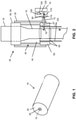
- FIG. 1 provides a schematic perspective view of an exemplary optical preform 10 showing its possible layers including a core 15, a first cladding layer 20 and an overcladding layer 25, such as are sometimes manufactured using CVD, RIT and RIC technologies.
- the transparent cylindrical articles need not be optical preforms, but instead may be a transparent core rod having an outer diameter, or a transparent cylinder having outer and inner diameters, or another article that happens to be cylindrical or tube-like and transparent but which does not relate to the fiber optics field. It is foreseen and intended that all such modifications and applications are included in the invention described and claimed hereinafter. Additionally, based on the detailed description provided herein, it is believed that persons of ordinary skill in the relevant art will recognize and be capable of making alterations and modifications to the embodiments disclosed herein.
- the term "vitreous" has its usual meaning of describing material that is similar to (i.e., has the characteristics or appearance of) glass such as transparency, brittleness, hardness, glossiness, etc.
- the term "transparent” has its usual meaning of describing material that transmits light without appreciable scattering so that bodies positioned on the other side of the material from an observer are seen clearly. This does not require perfect or exact transmission of light, but means that light is allowed to pass through such material with little or no interruption or distortion so that objects on the other side can be seen and recognized.
- the invention includes apparatus for measuring the diameter of a transparent cylindrical article during its manufacture in a high temperature furnace.
- the type of furnace is not particularly limited in connection with the practice of the apparatus and method of the invention described herein. It is noted that while the furnace described in connection with various embodiments of the invention is a jacketed fluid cooled furnace, other types of furnaces are suitable when used to manufacture, modify or process a transparent cylindrical article which needs measurement.
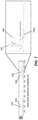
- FIG. 2 provides a schematic elevational front view of a typical high temperature furnace 30 with an optical preform 10 passing therethrough.
- the furnace 30 shown in FIG. 2 is a jacketed fluid cooled furnace 30 having an outer jacket 35 which is shown in cross section to reveal the main heating region 40 having a heated interior 45 with upper and lower annular graphite contacts 50, 60 through which the cylindrical article, such as the optical preform 10, passes while being heated.
- the upper and lower contacts 50, 60 each have annular walls 55, 65 and are proximate opposite ends of the heated interior 45, as shown in FIG. 2 .
- the furnace 30 has a protection tube 125 where the heated preform 10 begins to cool and solidify.
- the furnace 30 has a lateral opening 70 through which the preform 10 inside the furnace 30 is visible to observers from the exterior environment. Accordingly, the lateral opening 70 is in communication with the heated interior 45 of the furnace 30, through which the preform 10 is passed during heating. Furthermore, the lateral opening 70 is at a vertical elevation where it is desired to measure the diameter of the preform 10, such as in the embodiment shown where heating of the preform 10 is substantially complete and just before or at the point at which the preform begins to cool. More particularly, the lateral opening 70 passes through an opening 67 in the annular wall 65 of the lower annular contact 60, through the wall of the jacket 35, and through a protective bridge 72, so that the lateral opening 70 is also in communication with the exterior environment.
- a fluid-tight, fluid-cooled housing 75 is used to contain and protect a digital camera 100 and its lens 105.
- the lens 105 is a wide angle lens (e.g., for a full-frame 35 mm image sensor, a lens having a focal length of less than 35 mm). In other embodiments, the lens 105 may be a normal or a long-focus lens.
- the housing 75 has a portal 80 and is affixed to the exterior of the furnace 30 such that the portal 80 is aligned with the lateral opening 70 so that the preform 10 is visible from within the housing 75.
- Figure 3 shows a schematic top plan view of the apparatus for measuring the preform diameter including the camera 100, the lens 105 and the housing 75 which contains and protects the camera 100 and the lens 105. Also shown in FIG. 3 is the relative positioning of the lower contact 60 of the furnace 30 and the protective bridge 72 with the camera 100 and the lens 105, which enables a clear field of view (FOV, shown with a pair of dotted lines) between the lens 105 and the preform 10 inside the furnace 30 and passing through the lower contact 60.
- the mirror 110 is not visible since it lies beneath the camera 100 and the lens 105 in this top plan view.
- the upper and lower contacts 50, 60 receive and conduct electric current therethrough for heating the interior 45 of the furnace 30 with the preform 10 therein.
- the fact that the contacts 50, 60 conduct electricity and are part of the heating mechanism for the furnace 30 means that there are structural and functional limitations to the size (i.e., height and width) of the opening in the wall of the lower contact 60.
- the apparatus for measuring the diameter of a transparent cylindrical article during its manufacture includes: (A) the digital camera 100 having thelens 105 affixed thereto and a sensing and digital recording device, such as, for example, a charge-coupled device (“CCD") image sensor (inside camera, not shown); and (B) a digital processor (not shown per se) programmed with an algorithm.
- the sensing and digital recording device may be a complementary metal-oxide-semiconductor (CMOS) image sensor.
- CMOS complementary metal-oxide-semiconductor
- the camera 100 and the lens 105 are positioned to enable the lens 105 to receive an optical image of the preform 10 article through the lateral opening 70.
- the lens 105 directs the optical image to the image sensor which converts the optical image to a digital image and records a digital image of the preform 10.
- the apparatus may further comprising a reflector, such as a mirror 110 positioned intermediate the lateral opening 70 of the furnace 30 and the lens 105 of the camera 100.
- the reflector directs the optical image (see arrows 115 in FIG. 2 ), which is received through the lateral opening 70 of the furnace 30 and portal 80 of the housing 75, to the lens 105 of the camera 100.
- the lens 105 and the mirror 110 may be affixed to a mounting bar 120 within the housing 75, as shown schematically in FIG. 2 .
- the apparatus also includes a digital processor programmed with an algorithm which accesses and interprets the digital image from the image sensor, and determines and reports the diameter of the cylindrical article.
- Suitable processors and algorithms include those known now and in the future capable of analyzing digital images. Exemplary processors and algorithms are described in further detail hereinbelow in connection with the method of the invention.
- the invention provides a method for measuring the diameter of a transparent cylindrical article during its manufacture in a high temperature furnace having a lateral opening through which the cylindrical article is visible.
- the method includes the basic steps of: (A) receiving an optical image of the cylindrical article emitted through the lateral opening using a camera having a lens affixed thereto; (B) directing the optical image to a sensing and digital recording device; (C) converting the optical image to a digital image, and recording the digital image, using the sensing and digital recording device; and (D) interpreting the digital image and determining the diameter of the cylindrical article using a processor programmed with an algorithm.
- an optical image 115 of the cylindrical article (e.g., preform 10) emitted through the lateral opening 70 of the furnace 30 is received by the camera 100 and the lens 105.
- the optical image 115 is directed to a sensing and digital recording device, also inside the camera (not shown), which then converts the optical image to a digital image, which is recorded.
- a processor programmed with an algorithm which may be part of the camera 100, or may be a separate microprocessor, or part of a computer, etc., interprets the digital image to determine the diameter of cylindrical article (preform 10), as well as other properties, including but not limited to the position of the center of the cylindrical article (preform 10) and the existence and location of any joints in the core rod 15 (see FIG. 1 ) of a preform 10.
- the last step (D) of interpreting the digital image and determining the diameter of the cylindrical article requires use of a processor programmed with an algorithm.
- the processor may, for example, without limitation, a computer, a computer component integrated with process control equipment and systems, a stand-alone microprocessor, or any other programmable processor known now or in the future to persons of ordinary skill that is capable of performing the algorithm, which will now be described in detail.
- the algorithm includes the steps of: (1) cropping the digital image to produce a smaller cropped digital image; (2) producing a gradient filtered image from the cropped digital image; (3) performing multiple gradient line scans and sum them together to form a grey level gradient spectrum; (4) identifying which of multiple peaks in the grey level gradient spectrum represent the true left- and right-side edges of the preform; (5) calculating the outer diameter of the preform using the values of the true left- and right-side edges of the preform; and (6) reporting the outer diameter of the preform.
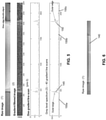
- FIG. 5 Sample images and spectra resulting from steps (1) to (4) of the algorithm are provided in FIG. 5 .
- the digital image is cropped to remove surrounding dark space and produce a smaller cropped digital image (see "Raw image” (1) in FIG. 5 ).
- the smaller cropped image (1) includes only the bright field of view visible through the lateral opening of the furnace.
- a gradient filtered image (2) (see “Gradient filtered image” (2) in FIG. 5 ) is produced by applying a standard deviation filter to the cropped digital image (1).
- the standard deviation filter operates by creating the gradient filtered image (2) where each pixel of the gradient filtered image (2) is equal to a standard deviation of the pixels within a surrounding area of the corresponding pixel of the cropped digital image (1). Because the standard deviation of a pixel of the cropped digital image (1) will be highest where the surrounding area shifts from light to dark, or vice versa, the gradient filtered image (2) is used to detect edges in the cropped digital image (1).
- the grey level gradient spectrum (3) may have an improved signal-to-noise ratio when including the sum of multiple line scans.
- the grey level gradient spectrum (3) includes the sum of about 40 to 50 line scans. In other embodiments, the grey level gradient spectrum (3) may include more than 50 or less than 40 line scans.
- the multiple gradient lines are scanned within a scan area proximate to a vertical center of the gradient filtered image (2) and extending horizontally across at least a portion of the full width of the gradient filtered image, i.e., sufficiently to encompass the entire width of the preform being measured (see white line 140 within the raw image of FIG. 6 to see approximate position of the scan area).
- Each line scan is performed by selecting a horizontal scan line position within the scan area of the gradient filtered image (2) and recording the grey level of the image along the set horizontal scan line position (see, e.g., "One gradient scan line" (pre-3) in FIG. 5 ).
- the grey level gradient spectrum image (3) After collecting and summing the line scans of the gradient filtered image (2), the grey level gradient spectrum image (3) has multiple left-sided peaks 145, multiple right-sided peaks 150 and multiple minor background peaks 155a, 155b, 155c (again, see spectrum (3) in FIG. 5 ).
- the grey level gradient spectrum image (3) may have only one left-sided peak, only one right-sided peak, and/or one or no minor background peaks.
- the left- and right-sided peaks 145, 150 contain the true left-sided and right-sided edges of the preform among them, respectively.
- the minor background peaks 155a, 155b, 155c represent noise resulting from the complex light background as well as the surface condition of the background graphite elements.
- minor it is meant that these background peaks 155a, 155b, 155c are generally shorter or small than the left- and right-sided peaks of interest and need not be considered when measuring the preform diameter.
- the true left- and right-side edges of the preform are identified from among the multiple left-sided and right-sided peaks 145, 150 in the grey level gradient spectrum (3).
- a grey level gradient spectrum analysis (4) is performed by selecting a left-sided peak window area 160 on the grey level gradient spectrum which encompasses the multiple left-sided peaks 145.
- a right-sided peak window area 165 is also selected on the grey level gradient spectrum which encompasses the multiple right-sided peaks 150.
- Identification of the true left- and right-side edges of the preform from the grey level gradient spectrum (4) (step (4), FIG. 7 ) further includes establishing a baseline for peak detection to eliminate the minor background peaks from further analysis. This is accomplished by, first, dynamically sampling a portion of the minor background peaks 155c and calculating a noise floor level based on the results of the dynamic sampling. The baseline is then derived by adding a predetermined threshold amount to the noise floor level. Thereafter, any peaks below the baseline are ignored for processing and analysis purposes.
- the threshold amount is determined by subtracting the noise floor level from the maximum peak height of the window selected of the grey level gradient spectrum (4), and then dividing the resulting height by a predetermined factor, where the factor is great enough to eliminate an identified noise peak such as peak E of FIG. 7 , but not eliminate potential true edge peaks such as peak D of FIG. 7 .
- the factor may be about 3.
- the predetermined threshold amount may be determined by, for example, calculating 0.5 times the average height of the portion of minor background peaks dynamically sampled.
- the target left-sided peak and the target right-sided peak are each identified.
- the multiple right-sided peaks 150 (all of which are higher than the baseline) in the right-sided peak window area 165 are analyzed and the peak which is positioned farthest to the right (peak D) in the right-sided peak window area 165 is selected to be the target right-sided peak.
- the position of the target right-sided peak is recorded as a numerical value equal to the true right-sided edge of the preform.
- the same analysis and selection procedure is applied to the multiple left-sided peaks 145 (all of which are also higher than the baseline) in the left-sided peak window area 160, and the position of the target left-sided peak is recorded as a numerical value equal to the true left-sided edge of the preform.
- the minor background peaks 155a, 155b, 155c can be ruled out in the window areas 160, 165.
- peaks A and E are ruled out by the baseline, while peaks B, C and D are left as peak candidates. Then peak D is identified as the target right-sided peak by its location at the right-most position in the right-sided peak window area 165.
- the outer diameter (OD) of the preform is calculated by finding the difference between the values of the true left- sided edge and the right-sided edge of the preform, and then taking the absolute value of that difference.
- the OD of the preform may then be reported, or be the subject of further analysis and decision-making.
- the average grey level in the cropped digital image may be calculated by the processor, and if it is below a predetermined threshold value, cease running the algorithm.
- the predetermined threshold value is selected based on the grey scale in use and should be a value low enough that persons of ordinary skill believe that when the average grey level in the cropped digital image is equal to or less than the threshold value it is reasonable to assume that the furnace is not in operation.
- the predetermined threshold value may be determined by collecting an image of the oven from the camera while confirmed to not be in operation and determining the mean gray level of all the pixels of the image.
- the image is a 8-bit grayscale image (i.e., 256 shades of gray)
- the mean gray level of the oven while not in operation may be 8 or below.
- the predetermined threshold value will vary from embodiment to embodiment based on oven design and the particular application.
- a mask (not shown) is applied in the center region of the preform to avoid interface defects/bubbles confusing the peak locking.
- the mask may be to be activated once the preform passes the start-up dripping phase, after which the preform OD does not change size quickly anymore. So, the left and right edges are being tracked for its last 20 locations, respectively. The (max - min) of the locations are calculated for each side of the edge. If the (max-min) of the locations is less than certain threshold for both glass edges, it means that the glass OD has reached sufficient stability. Therefore, the mask indicator is updated from 0 to 1.
- the preform OD becomes small again. Therefore, at that point, the mask should be disabled.
- Preform center location Location of left-handed edge + OD / 2 .
- FIGS. 8 , 9 and 10 are provided to facilitate description of algorithms for common core joint detection using the above-discussed apparatus and digital images.
- a joint between core rods, or even the leading end of a first core rod can be identified online using the method and apparatus of the invention.
- Such joint identification involves a first step, after production of the grey level gradient spectrum (see FIG. 5(3) and FIG. 8(A) ), of determining whether there exist multiple intermediate peaks 185 located intermediate the multiple left- and right-sided peaks 145, 150 in the grey level gradient spectrum (A), by (a) selecting a central window area 190 intermediate multiple the left- and right-sided peaks 145, 150 ( FIG.
- the area of integration may be analyzed by visual inspection by the operator, who subjectively identify when the area of integration has a sufficient value to indicate a joint. In other embodiments, the area of integration may be automatically analyzed to determine when the area of integration exceeds a predetermined value, which may vary from one application to another. When the area of integration exceeds the integration threshold value, a clear joint signal J is present, see FIG. 8 (B) and (C) , which can then be analyzed as described above in connection with the multiple left- and right-sided peaks to determine the size of the joint in the core rod.
- Detection of the first core joint may be of significant importance to start-up control of the preform manufacture process.
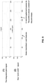
- the first core joint is often interfered with by weld features (see FIG. 9 ) producing distracting weld peaks 195 in the grey level gradient spectrum.
- Such weld peaks 195 representing the first core joint may be more elongated compared with subsequent joints in the core rod. Therefore, a more sophisticated algorithm that captures the first core joint better has also been developed.
- FIG. 9 provides a comparison of this new "J width signal" (2) with the "J signal" (1) as described above.
- a central area window 190 is selected intermediate multiple the left- and right-sided peaks 145, 150, in the grey level gradient spectrum.
- Central area window 190 encompasses the multiple intermediate peaks 200 which represent the location of the joint, including the joint's left and right edges (not shown per se).
- a baseline for peak detection is established to eliminate minor background peaks from further analysis, as described above for algorithm step (4).
- the outermost left- and right-sided peaks are each identified from among the multiple intermediate peaks 200 in the central window area 190 and their values are assigned as the locations of the true left- and right-sided edges of the joint, respectively.
- Joint width may then be calculated, as above for the width (diameter) of the preform, by finding the difference between the values of the true left and right edges of the joint.
- the joint width may then be reported, or be the subject of further analysis and decision-making.
- a verification step may be performed before reporting values relating to an assumed core joint, where if the location of the joint center is too far (a thresh-holding) away from the preform center, it will be assumed that the feature detected is not actually a core joint and no positions for edges or width of the feature will be reported.
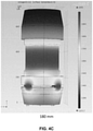
- FIGS. 4A , 4B and 4C The graphic results of the numerical modelling, which displayed the heating patterns achieved within the heating region 40 are is provided in FIGS. 4A , 4B and 4C . More specifically, FIG. 4A shows an acceptably uniform heating pattern with the original opening 67 of 130mm. FIG. 4B also shows that an opening 67 widened to 150mm still produces a heating pattern that is uniform and acceptable. When the opening 67 is widened to 180mm, however, the numerical model predicted that the heating region 40 would be heated unevenly to an unacceptable degree, as shown in FIG. 4C .
- Lenses 16mm fixed focal length MP lens from Edmund Optics. The focal length used depended on the desired field of view (FOV) and distance between the lens and the target preform. 16mm was appropriate for this application.
- FOV field of view
Landscapes
- Physics & Mathematics (AREA)
- General Physics & Mathematics (AREA)
- Engineering & Computer Science (AREA)
- Chemical & Material Sciences (AREA)
- Life Sciences & Earth Sciences (AREA)
- Analytical Chemistry (AREA)
- Health & Medical Sciences (AREA)
- Biochemistry (AREA)
- General Health & Medical Sciences (AREA)
- Immunology (AREA)
- Pathology (AREA)
- Computer Vision & Pattern Recognition (AREA)
- Theoretical Computer Science (AREA)
- Textile Engineering (AREA)
- Optics & Photonics (AREA)
- Quality & Reliability (AREA)
- Geometry (AREA)
- Astronomy & Astrophysics (AREA)
- General Life Sciences & Earth Sciences (AREA)
- Geochemistry & Mineralogy (AREA)
- Manufacturing & Machinery (AREA)
- Materials Engineering (AREA)
- Organic Chemistry (AREA)
- Length Measuring Devices By Optical Means (AREA)
Description
- The present invention relates generally to an apparatus and method for heating and measuring of transparent cylindrical articles during their manufacture. Such articles include, for example, optical fiber preforms which have at least two layers of vitreous material and from which optical fibers are made.
- Optical fibers are waveguides that transmit light, with minimal scattering and attenuation, between two locations. Optical fibers, also sometimes called fiber optics, are well known and used for illumination, communications, information transfer, and sensors, for example. Optical fibers are typically flexible and very thin, i.e., on the order of less than the thickness of a human hair. They have a transparent core and one or more transparent cladding layers. The core and cladding layers are made of vitreous material, such as high quality glass (made from, e.g., silica, fluoride, phosphates, etc.) or even certain plastics. Moreover, the core material has a refractive index which is greater than the refractive index of the material in the surrounding cladding layer or layers. These conditions enable total internal reflection of light signals passing through the fiber, resulting in an efficient waveguide.
- Optical fibers are generally manufactured by drawing the fiber from a heated preform using a fiber drawing tower. Such towers are typically vertically oriented and have a guide to hold and guide a preform, end first, into the top of the tower, as well as a high temperature furnace to heat the preform in a controlled manner, and apparatus to apply controlled tension to the leading end of the preform, whereby a fiber of molten material forms. The fiber is typically cooled and solidified as it is drawn from the preform to provide a fine continuous optical fiber.
- The preforms are generally cylindrical or tubular in overall shape, with circular cross-sectional profiles, but may have other cross-section profiles (e.g., oval, elliptical, angular, etc.). Like the fibers which are drawn from them, preforms have an axial core of transparent vitreous material which is selected and formulated to provide the particular light transmitting properties needed, such as refractive index, attenuation, etc., according to its intended end uses. The preform core is completely surrounded and enclosed by at least one cladding layer which is also made of transparent vitreous material, but which has a lower refractive index than that of the core.
- There are several techniques practiced for making optical preforms, most of which involve one or more types of chemical vapor deposition (CVD), including inside vapor deposition, outside vapor deposition and vapor axial deposition. All such techniques generally involve depositing one or more layers of soot material onto a substrate, followed by high temperature heating to vitrify the deposited soot materials into solid glass. The substrate may be a rod of material that can withstand the subsequent high temperature heating, or it may be a previously deposited layer of soot material, or a previously formed and vitrified rod or layer of glass, or even some combination of these. In some cases, the heating step which vitrifies the layered soot material may be performed immediately prior to, or concurrently, with heating of the vitrified preform and drawing of the fiber, so that formation of the preform and formation of the fiber are sequential and continuous.
- CVD techniques may be combined with more recently developed processes, known as rod-in-tube (RIT) and rod-in-cylinder (RIC), for manufacturing optical preforms. RIT and RIC methods both start with a core glass rod and a glass jacket (either a tube or cylinder). The core glass rod has a core and a primary cladding layer, both of which are transparent, and the refractive index of the core is greater than that of the primary cladding layer. The glass jacket provides a second layer of glass cladding material, also sometimes referred to as "overcladding." The glass jacket may be a large outer diameter cylinder, or the cylinder may be drawn into a smaller outer diameter tube, both of which have an axial opening sized to receive the core glass rod. The core glass rod and glass jacket are produced separately and then assembled by insertion of the core rod into the tube or cylinder, followed by heating and solidification in a verticallyoriented jacketing apparatus similar to the fiber drawing tower, to form a solid vitreous preform. The preform is then be fed to a fiber drawing tower, where it is heated and the optical fiber drawn from the leading edge of the heated preform.
- It is clear that careful control of the amounts of soot materials deposited during CVD methods, as well as control of the dimensions (inner diameter, outer diameter, length, etc.) of the core rod and the tube or cylinder jackets before and during vitrification, and the diameter and thickness of the final optical fiber and its layers, are all of critical importance to ultimately producing optical fibers having the desired properties and quality. Therefore, there are various known methods and apparatus for measuring the various properties of the components of the preform, the preform itself, and the optical fiber during different stages of the overall manufacture process.
- For example, the diameter of optical preforms, whether made by CVD, RIT, RIC, or other methods, is typically measured after vitrification, but before beginning the drawing of optical fibers therefrom. One such method involves directing a laser or other radiation beam at a preform, where the laser or beam is at a right angle to the longitudinal axis of the preform and is reciprocated back and forth from one side of the preform to the other, linearly in a plane also oriented at a right angle to the longitudinal axis of the preform. The image produced by such methods is recorded and analyzed to produce and report at least the outer diameter of the preform, and sometimes also the diameters of the core and cladding layers, as well as other information. Often, the image is captured by an image sensor, such as a charge-coupled device ("CCD") image sensor, and recorded as a digital image for manipulation and interpretation by a processor. Laser scanning methods where the image sensor is located on the opposite side of the preform from the laser source and receives the shadow image produced as the laser shines through the preform are known as the shadow technique.
- There are limitations to the shadow measurement of diameter measurement, some of which are imposed by features of the apparatus. For example, typically the furnace apparatus in which heating and vitrification of the preform occur has an opening which is sized and shaped, often as a long narrow rectangle or slit, to accommodate the reciprocating scanning laser passing through the opening to the preform. Preforms produced by the RIT method can be manufactured having outer diameters (OD) up to about 110 millimeters (mm), and that diameter could be accurately measured using telecentric laser scanning gauges and image sensors appropriately installed and operated proximate to the furnace apparatus. Of course, due to the nature of laser scanning technology, the rectangular window or slit must be a bit wider than the widest preform to be measured and, for a time this was possible. However, customer demand for larger diameter preforms led to the development of the RIC method for manufacturing preforms having diameters between about 135 and 150 (mm), and even larger, and limitations of the geometry and function of the apparatus and the laser scanner technology required development of a new way to measure larger diameter preforms and equipment for practicing such a method.
- The present invention provides a novel apparatus and method for measuring the diameter of optical preforms, or other optically transparent cylindrical articles, during their manufacture. The novel apparatus includes use of a digital camera having a lens and a image receiver and recorder, in place of the previously employed laser scanning apparatus, while the method employs an algorithm developed to analyze the image received by the image sensor in a manner which eliminates noise and redundancy in the image to determine the preform diameter.
-
JP 2009 209016 A -
DE 195 36 960 A1 discloses a device and method for production of a cylindrical glass component that involves softening a preform in a drawing furnace; continuously drawing the component from the softened region with formation of a drawing bulb; and constantly measuring one or more geometric dimensions of the component at a first measuring location in the region of the drawing bulb. A non-contact optical dimeter measuring device is positioned in the vicinity of the furnace for determining the diameter of the component within the drawing bulb. For that purpose, the furnace wall has a through hole. -
JP 2012 121761 A -
WO 2006/129494 A1 discloses measuring a transparent cylinder through an opening in a measuring cell using a digital camera with a processor interpreting the image and determining a measurement. -
US 4 882 497 A discloses using a camera and light source to measure the diameter of a cylindrical object, including edge detection. -
US 2003/160974 A1 discloses measuring cylindrical objects using a camera and a laser. -
US 2020/0101508 A1 shows a monitoring system for providing images and/or measure parameters in a hostile environment. The monitoring system includes a fluid cooled and fluid tight sensor housing which contains a sensor (borescope). The sensor housing has a cylindrical, tubular window and a cap member which is secured to the distal end of the tubular window. The borescope has an optical window which may capture images at virtually any desired angle or location. The image may be transferred via a bundle of optical fibers to a control box and to a monitor. Instead of the borescope a camera could be employed a camera which may be a CCD camera. - The present invention provides an apparatus for heating and measuring a transparent cylindrical article, such as its diameter, during its manufacture in a high temperature furnace. The high temperature furnace has a lateral opening through which the cylindrical article is visible. The apparatus includes: (A) a high temperature furnace; (B) a digital camera having a lens affixed thereto and a sensing and digital recording device; and (C) a digital processor programmed with an algorithm.
- The high temperature furnace comprises an upper graphite contact and a lower graphite contact, wherein each of the upper and the lower contact has an annular wall; and a heated interior positioned between the upper and lower contacts, wherein the annular wall of the lower contact has a lateral opening in communication with the heated interior and through which the cylindrical article is visible.
- The camera is enclosed in a fluid-tight, fluid-cooled housing having a portal, aligned with the opening of the furnace wall, for passage therethrough of the optical image of the cylindrical article.
- The lens receives an optical image of the cylindrical article through the opening of the furnace wall, and directs the optical image to the sensing and digital recording device of the camera which converts the optical image to a digital image and records the digital image. In an exemplary embodiment, the lens is a wide angle lens (e.g., for a full-
frame 35 mm image sensor, a lens having a focal length of less than 35 mm). In other embodiments, the lens may be a normal or a long-focus lens. The sensing and digital recording device may be a charge-coupled device ("CCD") image sensor. Alternatively, the sensing and digital recording device may be a complementary metal-oxide-semiconductor (CMOS) image sensor. The digital processor and algorithm accesses and interprets the digital image from the image sensor, and determines and reports the measurement of the cylindrical article, such as its diameter. - In some embodiments, the transparent cylindrical article may be an optical fiber preform comprising two or more layers of vitreous material. Moreover, the preform may include a core layer having a refractive index and a cladding layer having a refractive index and surrounding the inner layer. The refractive index of the core layer is greater than the refractive index of the cladding layer.
- The apparatus may further include a reflector, such as a mirror, for directing the optical image received through the opening of the furnace wall and portal of the fluid-cooled housing to the lens of the camera.
- In some embodiments of the apparatus of the invention, the furnace is a jacketed fluid-cooled graphite furnace, wherein the upper and lower contacts are proximate opposite ends of the heated interior, and wherein the upper and lower contacts receive and conduct electric current therethrough for heating the interior of the graphite furnace with the cylindrical article therein.
- Embodiments of the present invention may also include a method for measuring the diameter of a transparent cylindrical article during its manufacture in a high temperature furnace having a lateral opening through which the cylindrical article is visible. More particularly, the method may include: (A) receiving an optical image of the cylindrical article emitted through the lateral opening using a camera having a lens affixed thereto; (B) directing the optical image to a sensing and digital recording device; (C) converting the optical image to a digital image, and recording the digital image, using the sensing and digital recording device; and (D) interpreting the digital image and determining the diameter of the cylindrical article using a processor programmed with an algorithm. The sensing and digital recording device may be housed in the camera or it may be a device separate from the camera. The transparent cylindrical article may be an optical preform.
- The algorithm of the processor has the steps of: (1) cropping the digital image to produce a smaller cropped digital image; (2) producing a gradient filtered image from the cropped digital image; (3) performing multiple gradient line scans and sum them together to form a grey level gradient spectrum; (4) identifying peaks which represent true left- and right-side edges of the cylindrical article; (5) calculating the outer diameter of the cylindrical article by taking the absolute value of the difference between the values of the true left- and right-sided edge of the cylindrical article; and (6) reporting the outer diameter of the cylindrical article.
- More particularly, (1) the digital image is cropped to remove surrounding dark space and the resulting smaller cropped digital image includes only a bright field of view which was visible through the lateral opening of the furnace. Next, (2) a gradient filtered image is produced from the cropped digital image using a standard deviation light filter.
- The third step of the algorithm (3) requires performing multiple gradient line scans and sum them together to form a grey level gradient spectrum having multiple left-sided peaks, multiple right-sided peaks and multiple minor background peaks. The multiple gradient lines are scanned within a scan area proximate to a vertical center of the gradient filtered image and extending horizontally across the full width of the gradient filtered image.
- For the fourth step of the algorithm (4), identifying which of the multiple left- and right-sided peaks in the grey level gradient spectrum represent true left- and right-side edges of the preform is accomplished as follows. On the grey level gradient spectrum, a left-sided peak window area is selected which encompasses the multiple left-sided peaks, and a right-sided peak window area is selected which encompasses the multiple right-sided peaks, leaving the minor background peaks outside each window area for separate analysis. Then, a baseline is established for peak detection which eliminates the minor background peaks from further analysis by: (i) dynamically sampling a portion of the minor background peaks and calculating a noise floor level based on said dynamic sampling; (ii) adding a predetermined threshold amount to the noise floor level to derive said baseline; and (iii) thereafter, ignoring any peaks below the established baseline. Thereafter, a target left-sided peak and a target right-sided peak are identified to provide numerical values for the positions of the true left- and right-sided edges of the preform, respectively, by: (i) analyzing each of the multiple left-sided peaks which are higher than said baseline in the left-sided peak window area, selecting the target left-sided peak which is positioned farthest to the left in the left-sided peak window area and recording its position as a numerical value equal to the true left-sided edge of the preform; (ii) analyzing each of the multiple right-sided peaks which are higher than said baseline in the right-sided peak window area, selecting the target right-sided peak which is positioned farthest to the right in the right-sided peak window area and recording its position as a numerical value equal to the true right-sided edge of the preform.
- Finally, (5) the outer diameter of the cylindrical article is calculated by taking the absolute value of the difference between the values of the true left- and right-sided edge of the cylindrical article which were determined in the fourth step (4), and (6) the outer diameter of the cylindrical article is reported.
- The invention is defined in appended
independent claims 1, 5 and 12. - The invention is best understood from the following detailed description when read in connection with the accompanying drawing. It is emphasized that, according to common practice, the various features of the drawing are not to scale. On the contrary, the dimensions of the various features are arbitrarily expanded or reduced for clarity. Included in the drawing are the following figures:
-
FIG. 1 is a schematic perspective view of an exemplary optical preform showing the core and cladding layers; -
FIG. 2 is a schematic, partially cross-sectional, elevational front plan view of a high temperature furnace, a preform passing therethrough and an embodiment of the apparatus for measuring the preform diameter; -
FIG. 3 shows a schematic top plan view of the furnace, preform and apparatus for measuring the preform diameter; -
FIGS 4A ,4B and4C show the results of modeling the temperature pattern in the heated region of the furnace where the lower contact has an opening of varied width; -
FIG. 5 shows the graphic data product of the first three steps of the algorithm used to process the optical image received by the camera; -
FIG. 6 shows the approximate position of a scan window within which lines are selected for grey scale scanning in the third step of the algorithm; -
FIG. 7 shows the grey level gradient spectrum and details of its analysis during the fourth step of the algorithm; -
FIG. 8 shows sample graphic data relating to an algorithm for detection and measurement of a joint in the core of an optical preform; -
FIG. 9 shows comparative graphic data for simple and advanced algorithms for detection and measurement of a joint in the core of an optical preform; and -
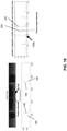
FIG. 10 shows a grey level gradient spectrum and details of its analysis for detection and measurement of a joint in the core of an optical preform. - Embodiments of the present invention may include an apparatus and method for measuring a transparent cylindrical articles, such as optical fiber preforms, during their manufacture. For example, without limitation, the transparent cylindrical articles include optical fiber preforms from which optical fibers are produced using a process known as drawing. Such optical preforms have at least two layers of vitreous material, a core and a cladding layer, where the core has a higher refractive index than the cladding layer. The preforms may, in some embodiments, have one or more additional layers of cladding, such as an "overcladding layer," which is also made of transparent vitreous material.
FIG. 1 provides a schematic perspective view of an exemplaryoptical preform 10 showing its possible layers including acore 15, afirst cladding layer 20 and anovercladding layer 25, such as are sometimes manufactured using CVD, RIT and RIC technologies. - It should be understood that while the invention is described in detail hereinafter in the context of measuring the diameter of such optical preforms, its application is not limited to measurement of optical preform diameters. Rather, as will be recognized by persons having ordinary skill in the relevant art, the transparent cylindrical articles need not be optical preforms, but instead may be a transparent core rod having an outer diameter, or a transparent cylinder having outer and inner diameters, or another article that happens to be cylindrical or tube-like and transparent but which does not relate to the fiber optics field. It is foreseen and intended that all such modifications and applications are included in the invention described and claimed hereinafter. Additionally, based on the detailed description provided herein, it is believed that persons of ordinary skill in the relevant art will recognize and be capable of making alterations and modifications to the embodiments disclosed herein.
- As used herein, the term "vitreous" has its usual meaning of describing material that is similar to (i.e., has the characteristics or appearance of) glass such as transparency, brittleness, hardness, glossiness, etc.
- As used herein, the term "transparent" has its usual meaning of describing material that transmits light without appreciable scattering so that bodies positioned on the other side of the material from an observer are seen clearly. This does not require perfect or exact transmission of light, but means that light is allowed to pass through such material with little or no interruption or distortion so that objects on the other side can be seen and recognized.
- In one general embodiment, the invention includes apparatus for measuring the diameter of a transparent cylindrical article during its manufacture in a high temperature furnace. The type of furnace is not particularly limited in connection with the practice of the apparatus and method of the invention described herein. It is noted that while the furnace described in connection with various embodiments of the invention is a jacketed fluid cooled furnace, other types of furnaces are suitable when used to manufacture, modify or process a transparent cylindrical article which needs measurement.
-
FIG. 2 provides a schematic elevational front view of a typicalhigh temperature furnace 30 with anoptical preform 10 passing therethrough. Thefurnace 30 shown inFIG. 2 is a jacketed fluid cooledfurnace 30 having anouter jacket 35 which is shown in cross section to reveal themain heating region 40 having a heated interior 45 with upper and lowerannular graphite contacts 50, 60 through which the cylindrical article, such as theoptical preform 10, passes while being heated. The upper andlower contacts 50, 60 each haveannular walls 55, 65 and are proximate opposite ends of theheated interior 45, as shown inFIG. 2 . Furthermore, thefurnace 30 has aprotection tube 125 where theheated preform 10 begins to cool and solidify. - With reference still to
FIG. 2 , thefurnace 30 has alateral opening 70 through which thepreform 10 inside thefurnace 30 is visible to observers from the exterior environment. Accordingly, thelateral opening 70 is in communication with theheated interior 45 of thefurnace 30, through which thepreform 10 is passed during heating. Furthermore, thelateral opening 70 is at a vertical elevation where it is desired to measure the diameter of thepreform 10, such as in the embodiment shown where heating of thepreform 10 is substantially complete and just before or at the point at which the preform begins to cool. More particularly, thelateral opening 70 passes through anopening 67 in theannular wall 65 of the lowerannular contact 60, through the wall of thejacket 35, and through aprotective bridge 72, so that thelateral opening 70 is also in communication with the exterior environment. - Since the
furnace 30 of this exemplary embodiment operates at high temperatures and is itself jacketed and fluid-cooled, a fluid-tight, fluid-cooledhousing 75 is used to contain and protect adigital camera 100 and itslens 105. In an exemplary embodiment, thelens 105 is a wide angle lens (e.g., for a full-frame 35 mm image sensor, a lens having a focal length of less than 35 mm). In other embodiments, thelens 105 may be a normal or a long-focus lens. Thehousing 75 has a portal 80 and is affixed to the exterior of thefurnace 30 such that the portal 80 is aligned with thelateral opening 70 so that thepreform 10 is visible from within thehousing 75. -
Figure 3 shows a schematic top plan view of the apparatus for measuring the preform diameter including thecamera 100, thelens 105 and thehousing 75 which contains and protects thecamera 100 and thelens 105. Also shown inFIG. 3 is the relative positioning of thelower contact 60 of thefurnace 30 and theprotective bridge 72 with thecamera 100 and thelens 105, which enables a clear field of view (FOV, shown with a pair of dotted lines) between thelens 105 and thepreform 10 inside thefurnace 30 and passing through thelower contact 60. Themirror 110 is not visible since it lies beneath thecamera 100 and thelens 105 in this top plan view. - It is noted that the upper and
lower contacts 50, 60 receive and conduct electric current therethrough for heating theinterior 45 of thefurnace 30 with thepreform 10 therein. The fact that thecontacts 50, 60 conduct electricity and are part of the heating mechanism for thefurnace 30 means that there are structural and functional limitations to the size (i.e., height and width) of the opening in the wall of thelower contact 60. - To obtain a wider field of view (e.g., see FOV in
FIG. 3 ) for more reliable measurements, as well as larger preform OD measurements, widening of the opening through thelower contact 60 was investigated using a numerical model to predict the effects of a wider opening on the uniformity of heating in theheating region 40 of thefurnace 30. The numerical model and its results are provided hereinbelow in the examples and shown inFIGS 4A ,4B and4C . An exemplary numerical model that may be used to determine the width of the opening is the Finite Element Method (FEM), though other numerical models are also contemplated. Based on the numerical modelling, it was determined that the opening could safely be widened to about 150mm for the particular embodiment disclosed herein. In other embodiments, the maximum width of the opening may be less than or greater than about 150 mm. A person of ordinary skill in the art will understand based on this disclosure how to determine the maximum width of the opening by numerical modelling. - Referring again to
FIGS. 2 and3 , the apparatus for measuring the diameter of a transparent cylindrical article during its manufacture includes: (A) thedigital camera 100 havingthelens 105 affixed thereto and a sensing and digital recording device, such as, for example, a charge-coupled device ("CCD") image sensor (inside camera, not shown); and (B) a digital processor (not shown per se) programmed with an algorithm. In other embodiments, the sensing and digital recording device may be a complementary metal-oxide-semiconductor (CMOS) image sensor. More particularly, thecamera 100 and thelens 105 are positioned to enable thelens 105 to receive an optical image of thepreform 10 article through thelateral opening 70. Thelens 105 directs the optical image to the image sensor which converts the optical image to a digital image and records a digital image of thepreform 10. - The apparatus may further comprising a reflector, such as a
mirror 110 positioned intermediate thelateral opening 70 of thefurnace 30 and thelens 105 of thecamera 100. The reflector directs the optical image (seearrows 115 inFIG. 2 ), which is received through thelateral opening 70 of thefurnace 30 andportal 80 of thehousing 75, to thelens 105 of thecamera 100. Thelens 105 and themirror 110 may be affixed to a mountingbar 120 within thehousing 75, as shown schematically inFIG. 2 . - In addition to the
digital camera 100, the apparatus also includes a digital processor programmed with an algorithm which accesses and interprets the digital image from the image sensor, and determines and reports the diameter of the cylindrical article. Suitable processors and algorithms include those known now and in the future capable of analyzing digital images. Exemplary processors and algorithms are described in further detail hereinbelow in connection with the method of the invention. - It may be desirable to take a second measurement of the
preform 10 after it has cooled and set, such as at the position in thefurnace 30 where thepreform 10 is emerging from theprotection tube 125, e.g., at location B inFIG. 2 . While the specific features are not shown inFIG. 2 , when second preform measurement is to be taken at location B, thefurnace 30 will have another lateral opening at location B, to enable viewing of the cooling preform exiting theprotective tube 125 from the external environment, as well as a second apparatus for measuring thecooling preform 10 at location B, including another camera having its own sensing and digital recording device and lens, and another fluid-cooled housing. All such features may be the same as described above in connection with the main measurement location, i.e., location A, where thepreform 10 is passing through thelower contact 60 of thefurnace 30. - In another general embodiment, the invention provides a method for measuring the diameter of a transparent cylindrical article during its manufacture in a high temperature furnace having a lateral opening through which the cylindrical article is visible. The method includes the basic steps of: (A) receiving an optical image of the cylindrical article emitted through the lateral opening using a camera having a lens affixed thereto; (B) directing the optical image to a sensing and digital recording device; (C) converting the optical image to a digital image, and recording the digital image, using the sensing and digital recording device; and (D) interpreting the digital image and determining the diameter of the cylindrical article using a processor programmed with an algorithm.
- With reference briefly back to the apparatus shown in
FIGS. 2 and3 , anoptical image 115 of the cylindrical article (e.g., preform 10) emitted through thelateral opening 70 of thefurnace 30 is received by thecamera 100 and thelens 105. Inside thecamera 100, with thelens 105 properly mounted and adjusted, as will be readily understood by persons of ordinary skill in the art, theoptical image 115 is directed to a sensing and digital recording device, also inside the camera (not shown), which then converts the optical image to a digital image, which is recorded. A processor programmed with an algorithm (not shown), which may be part of thecamera 100, or may be a separate microprocessor, or part of a computer, etc., interprets the digital image to determine the diameter of cylindrical article (preform 10), as well as other properties, including but not limited to the position of the center of the cylindrical article (preform 10) and the existence and location of any joints in the core rod 15 (seeFIG. 1 ) of apreform 10. - The last step (D) of interpreting the digital image and determining the diameter of the cylindrical article requires use of a processor programmed with an algorithm. The processor may, for example, without limitation, a computer, a computer component integrated with process control equipment and systems, a stand-alone microprocessor, or any other programmable processor known now or in the future to persons of ordinary skill that is capable of performing the algorithm, which will now be described in detail.
- Generally, the algorithm includes the steps of: (1) cropping the digital image to produce a smaller cropped digital image; (2) producing a gradient filtered image from the cropped digital image; (3) performing multiple gradient line scans and sum them together to form a grey level gradient spectrum; (4) identifying which of multiple peaks in the grey level gradient spectrum represent the true left- and right-side edges of the preform; (5) calculating the outer diameter of the preform using the values of the true left- and right-side edges of the preform; and (6) reporting the outer diameter of the preform. Each of these steps will now be described in further detail. Sample images and spectra resulting from steps (1) to (4) of the algorithm are provided in
FIG. 5 . - In the first step of the algorithm, the digital image is cropped to remove surrounding dark space and produce a smaller cropped digital image (see "Raw image" (1) in
FIG. 5 ). The smaller cropped image (1) includes only the bright field of view visible through the lateral opening of the furnace. - In the second step of the algorithm, a gradient filtered image (2) (see "Gradient filtered image" (2) in
FIG. 5 ) is produced by applying a standard deviation filter to the cropped digital image (1). The standard deviation filter operates by creating the gradient filtered image (2) where each pixel of the gradient filtered image (2) is equal to a standard deviation of the pixels within a surrounding area of the corresponding pixel of the cropped digital image (1). Because the standard deviation of a pixel of the cropped digital image (1) will be highest where the surrounding area shifts from light to dark, or vice versa, the gradient filtered image (2) is used to detect edges in the cropped digital image (1). - In the third step of the algorithm, multiple line scans of the gradient filtered image (2) are collected and summed together to form a grey level gradient spectrum (see "grey level gradient spectrum" (3) in
FIG. 5 ). While in some embodiments only one line scan may be collected, the grey level gradient spectrum (3) may have an improved signal-to-noise ratio when including the sum of multiple line scans. In an exemplary embodiment, the grey level gradient spectrum (3) includes the sum of about 40 to 50 line scans. In other embodiments, the grey level gradient spectrum (3) may include more than 50 or less than 40 line scans. More particularly, the multiple gradient lines are scanned within a scan area proximate to a vertical center of the gradient filtered image (2) and extending horizontally across at least a portion of the full width of the gradient filtered image, i.e., sufficiently to encompass the entire width of the preform being measured (seewhite line 140 within the raw image ofFIG. 6 to see approximate position of the scan area). Each line scan is performed by selecting a horizontal scan line position within the scan area of the gradient filtered image (2) and recording the grey level of the image along the set horizontal scan line position (see, e.g., "One gradient scan line" (pre-3) inFIG. 5 ). After collecting and summing the line scans of the gradient filtered image (2), the grey level gradient spectrum image (3) has multiple left-sided peaks 145, multiple right-sided peaks 150 and multipleminor background peaks FIG. 5 ). In some embodiments, the grey level gradient spectrum image (3) may have only one left-sided peak, only one right-sided peak, and/or one or no minor background peaks. The left- and right-sided peaks minor background peaks background peaks - In the fourth step of the algorithm, the true left- and right-side edges of the preform are identified from among the multiple left-sided and right-
sided peaks FIG. 7 , a grey level gradient spectrum analysis (4) is performed by selecting a left-sidedpeak window area 160 on the grey level gradient spectrum which encompasses the multiple left-sided peaks 145. Similarly, a right-sidedpeak window area 165 is also selected on the grey level gradient spectrum which encompasses the multiple right-sided peaks 150. These selections leave theminor background peaks peak window area 160 should be centered on the highest one of the multiple left-sided peaks 145, and likewise, the right-sidedpeak window area 165 should be centered on the highest one of the multiple right-sided peaks 150. - Identification of the true left- and right-side edges of the preform from the grey level gradient spectrum (4) (step (4),
FIG. 7 ) further includes establishing a baseline for peak detection to eliminate the minor background peaks from further analysis. This is accomplished by, first, dynamically sampling a portion of theminor background peaks 155c and calculating a noise floor level based on the results of the dynamic sampling. The baseline is then derived by adding a predetermined threshold amount to the noise floor level. Thereafter, any peaks below the baseline are ignored for processing and analysis purposes. The threshold amount is determined by subtracting the noise floor level from the maximum peak height of the window selected of the grey level gradient spectrum (4), and then dividing the resulting height by a predetermined factor, where the factor is great enough to eliminate an identified noise peak such as peak E ofFIG. 7 , but not eliminate potential true edge peaks such as peak D ofFIG. 7 . In an exemplary embodiment, the factor may be about 3. In an alternative embodiment, the predetermined threshold amount may be determined by, for example, calculating 0.5 times the average height of the portion of minor background peaks dynamically sampled. - After eliminating the minor background peaks (noise and scatter data) from further consideration by the algorithm, numerical values for the positions of the true left- and right-sided edges of the preform, respectively, are obtained. First the target left-sided peak and the target right-sided peak are each identified. With reference now to
FIG. 7 , the multiple right-sided peaks 150 (all of which are higher than the baseline) in the right-sidedpeak window area 165 are analyzed and the peak which is positioned farthest to the right (peak D) in the right-sidedpeak window area 165 is selected to be the target right-sided peak. The position of the target right-sided peak is recorded as a numerical value equal to the true right-sided edge of the preform. While not shown per se, the same analysis and selection procedure is applied to the multiple left-sided peaks 145 (all of which are also higher than the baseline) in the left-sidedpeak window area 160, and the position of the target left-sided peak is recorded as a numerical value equal to the true left-sided edge of the preform. With reference still toFIG. 7 , by the foregoing analytical procedure, theminor background peaks window areas FIG. 7 , peaks A and E are ruled out by the baseline, while peaks B, C and D are left as peak candidates. Then peak D is identified as the target right-sided peak by its location at the right-most position in the right-sidedpeak window area 165. - Finally, the outer diameter (OD) of the preform is calculated by finding the difference between the values of the true left- sided edge and the right-sided edge of the preform, and then taking the absolute value of that difference. The OD of the preform may then be reported, or be the subject of further analysis and decision-making.
- It is possible and may be desirable, after the optical image is acquired and converted to a digital image by the sensing and digital recording device, to perform a check to be sure the furnace is in operation before continuing with the remaining steps of the algorithm. For example, optionally, the average grey level in the cropped digital image may be calculated by the processor, and if it is below a predetermined threshold value, cease running the algorithm. The predetermined threshold value is selected based on the grey scale in use and should be a value low enough that persons of ordinary skill believe that when the average grey level in the cropped digital image is equal to or less than the threshold value it is reasonable to assume that the furnace is not in operation. More particularly, the predetermined threshold value may be determined by collecting an image of the oven from the camera while confirmed to not be in operation and determining the mean gray level of all the pixels of the image. In am exemplary embodiment where the image is a 8-bit grayscale image (i.e., 256 shades of gray) the mean gray level of the oven while not in operation may be 8 or below. The predetermined threshold value will vary from embodiment to embodiment based on oven design and the particular application.
- In some embodiments, as the preform OD grows and reaches certain size, a mask (not shown) is applied in the center region of the preform to avoid interface defects/bubbles confusing the peak locking. The mask may be to be activated once the preform passes the start-up dripping phase, after which the preform OD does not change size quickly anymore. So, the left and right edges are being tracked for its last 20 locations, respectively. The (max - min) of the locations are calculated for each side of the edge. If the (max-min) of the locations is less than certain threshold for both glass edges, it means that the glass OD has reached sufficient stability. Therefore, the mask indicator is updated from 0 to 1. Starting from the next loop, once the program sees the indicator=1, it will open this mask and only scan the image horizontal gradient for the regions outside the mask. However, at the end phase of the draw, the preform OD becomes small again. Therefore, at that point, the mask should be disabled. The disabling point may be determined by seeing that the mask indicator=1 and preform OD is less than certain threshold.
- Once the two glass edges are identified for OD calculation, another useful info that can be immediately derived is the preform center location. Its calculation formula is simply:

- This information can be very helpful for the szug operator to improve preform bow. Once they see the center location oscillation amplitude passes a certain threshold, they would start to use "bow-bar" to dampen the center location oscillation and therefore correct potential bow formation to the preform.
-
FIGS. 8 ,9 and10 are provided to facilitate description of algorithms for common core joint detection using the above-discussed apparatus and digital images. With the digital camera image produced by thecamera 100, a joint between core rods, or even the leading end of a first core rod, can be identified online using the method and apparatus of the invention. Such joint identification involves a first step, after production of the grey level gradient spectrum (seeFIG. 5(3) andFIG. 8(A) ), of determining whether there exist multiple intermediate peaks 185 located intermediate the multiple left- and right-sided peaks central window area 190 intermediate multiple the left- and right-sided peaks 145, 150 (FIG. 5(3) ), (b) calculating an area of integration for thatcentral window area 190 and (c) analyzing the area of integration to determine if a joint is present. The area of integration may be analyzed by visual inspection by the operator, who subjectively identify when the area of integration has a sufficient value to indicate a joint. In other embodiments, the area of integration may be automatically analyzed to determine when the area of integration exceeds a predetermined value, which may vary from one application to another. When the area of integration exceeds the integration threshold value, a clear joint signal J is present, seeFIG. 8 (B) and (C) , which can then be analyzed as described above in connection with the multiple left- and right-sided peaks to determine the size of the joint in the core rod. - Detection of the first core joint may be of significant importance to start-up control of the preform manufacture process. However, the first core joint is often interfered with by weld features (see
FIG. 9 ) producing distracting weld peaks 195 in the grey level gradient spectrum. Such weld peaks 195 representing the first core joint may be more elongated compared with subsequent joints in the core rod. Therefore, a more sophisticated algorithm that captures the first core joint better has also been developed.FIG. 9 provides a comparison of this new "J width signal" (2) with the "J signal" (1) as described above. - For example, once it is determined that a joint exists in the
preform 10, the grey level gradient spectrum is analyzed to determine the size and location of the joint. Similarly to the above-described method for determining the true left- and right-side edges of the preform (algorithm step (4)), as shown inFIG. 10 , acentral area window 190 is selected intermediate multiple the left- and right-sided peaks Central area window 190 encompasses the multipleintermediate peaks 200 which represent the location of the joint, including the joint's left and right edges (not shown per se). Next a baseline for peak detection is established to eliminate minor background peaks from further analysis, as described above for algorithm step (4). Then, numerical values for the positions of the true leftand right-sided edges of the joint, respectively, are may be obtained. The outermost left- and right-sided peaks are each identified from among the multipleintermediate peaks 200 in thecentral window area 190 and their values are assigned as the locations of the true left- and right-sided edges of the joint, respectively. Joint width may then be calculated, as above for the width (diameter) of the preform, by finding the difference between the values of the true left and right edges of the joint. The joint width may then be reported, or be the subject of further analysis and decision-making. Furthermore, the location of the center of the joint may be determined using the following formula:
- Additionally, a verification step may be performed before reporting values relating to an assumed core joint, where if the location of the joint center is too far (a thresh-holding) away from the preform center, it will be assumed that the feature detected is not actually a core joint and no positions for edges or width of the feature will be reported.
- The invention and its various embodiments described above will be better understood with reference to the following examples, which are merely particular embodiments of the invention in practice and in no way limit the scope of the apparatus or method of the invention.
- The opening through the
wall 65 of thelower contact 60 was initially 130mm. That width was sufficient for the previously used telecentric laser scanning method, but not for measuring preforms having diameters greater than about 130mm. A numerical model was used to estimate the width at which a widened opening would cause unacceptable impacts on furnace temperature and uniformity throughout theheating region 40. The graphic results of the numerical modelling, which displayed the heating patterns achieved within theheating region 40 are is provided inFIGS. 4A ,4B and4C . More specifically,FIG. 4A shows an acceptably uniform heating pattern with theoriginal opening 67 of 130mm.FIG. 4B also shows that anopening 67 widened to 150mm still produces a heating pattern that is uniform and acceptable. When theopening 67 is widened to 180mm, however, the numerical model predicted that theheating region 40 would be heated unevenly to an unacceptable degree, as shown inFIG. 4C . - Camera Equipment Used: "Guppy" 5 megapixel (MP) camera from Allied Vision Technologies, Modell F-503B.
- Software: Allied Vision Technologies standard Firepackage v 3.1 was used to capture images from the camera . It is noted that other commercial, or even custom, programs may be used for this function.
- Lenses: 16mm fixed focal length MP lens from Edmund Optics. The focal length used depended on the desired field of view (FOV) and distance between the lens and the target preform. 16mm was appropriate for this application.
- Filters: (a) Neutral density filters for attenuation of intense furnace light. Different combinations of such filters were used at upper vs. lower positions, including various optical densities; ( b) Red color filter to increase greyscale image contrast between glass edges and graphite background (i.e., the inner surface of the lower contact and lower protection tube); (c) Linear polarizing filter was used to remove unwanted reflections from glass surface that would interfere with measurement.
Claims (13)
- Apparatus for heating and measuring a transparent cylindrical article (10) during its manufacture , said apparatus comprising(A)a high temperature furnace (35; 49; 45; 55, 65) comprising an upper graphite contact (50) and a lower graphite contact (60), wherein each of the upper and the lower contact (50; 60) has an annular wall (55; 65) and the contacts are part of the heating mechanism for the furnace; and a heated interior positioned
between the upper and lower contacts (50; 60), wherein the annular wall (65) of the lower contact (60) has a lateral opening (67; 70) in communication with the heated interior (45) and through which the cylindrical article (10) is visible(B) a digital camera (100) having a lens (105) affixed thereto and a sensing and digital recording device, wherein the lens (105) receives an optical image (115) of the cylindrical article (10) through the opening (67; 70) of the lower annular wall (65), and directs the optical image (115) to the sensing and digital recording device which converts the optical image (115) to a digital image and records the digital image. wherein the camera (100) is enclosed in a fluid-tight, fluid-cooled housing (75) having a portal (80), aligned with the opening (67; 70) of the furnace wall, for passage therethrough of the optical image of the cylindrical article (10); and(C) a digital processor programmed with an algorithm which accesses and interprets the digital image from the sensing and digital recording device, and determines and reports a measurement of the cylindrical article (10), - The apparatus of Claim 1, wherein the transparent cylindrical article is an optical fiber preform (10) comprising two or more layers of vitreous material, and wherein the preform (10) comprises a core layer (15) having a refractive index and a cladding layer (20) having a refractive index and surrounding the inner layer (15); wherein the refractive index of the core layer (15) is greater than the refractive index of the cladding layer (20).
- The apparatus of claim 1, wherein the sensing and digital recording device comprises a charge-coupled device ("CCD") image sensor,
preferably the apparatus further comprising a reflector (110) for directing the optical image received through the opening (67; 70) of the furnace wall (65) and portal of the fluid-cooled housing (75) to the lens (105) of the camera (100). - The apparatus of Claim 1, wherein the furnace is a jacketed fluid-cooled graphite furnace (35; 49; 45; 55, 65), wherein the upper and lower contacts (50; 60) are proximate opposite ends of the heated interior (45), and wherein the upper (50) and lower contacts (60) receive and conduct electric current therethrough for heating the interior of the graphite furnace (35; 49; 45; 55, 65) with the cylindrical article (10) therein.
- A method for measuring the diameter of a transparent cylindrical article (10) during its manufacture in a high temperature furnace (35; 49; 45; 55, 65) having a lateral opening (67; 70) through which the cylindrical article (10) is visible; said method comprising:(A) receiving an optical image of the cylindrical article (10) emitted through the lateral opening (67; 70) using a camera (100) having a lens (105) affixed thereto;(B) directing the optical image to a sensing and digital recording device;(C) converting the optical image to a digital image, and recording the digital image, using the sensing and digital recording device; and(D) interpreting the digital image and determining the diameter of the cylindrical article using a processor programmed with an algorithm wherein the algorithm comprises the steps of:(1) cropping the digital image to remove surrounding dark space and produce a smaller cropped digital image which includes only a bright field of view which was visible through the lateral opening of the furnace (35; 49; 45; 55, 65), wherein the cropped digital image has a height and a width;(2) producing a gradient filtered image from the cropped digital image using a standard deviation filter;(3) performing multiple line scans and summing them together to form a grey level gradient spectrum having one or more left-sided peaks (145), one or more right-sided peaks (150) and one or more minor background peaks (155a; 155b; 155c), wherein the multiple gradient lines are scanned within a scan area proximate to a vertical center of the gradient filtered image and extending horizontally across the full width of the gradient filtered image;(4) identifying which of the one or more left-sided peaks (145) and the one or more right-sided peaks (150) in the grey level gradient spectrum represent true left- and right-side edges of the cylindrical article (10), by performing the following steps:(a) on the grey level gradient spectrum, select a left-sided peak window area (160) which encompasses the multiple left-sided peaks (145), and select a right-sided peak window area (165) which encompasses the multiple right-sided peaks (150), leaving the minor background peaks (155a; 155b; 155c) outside each window area (160; 165) for separate analysis;(b) establish a baseline for peak detection which eliminates the minor background peaks (155a; 155b; 155c) from further analysis by:(i) dynamically sampling a portion of the minor background peaks (155a; 155b; 155c) and calculating a noise floor level based on said dynamic sampling;(ii) determining a baseline by adding to the noise floor level a threshold value;(iii) thereafter, ignoring any peaks below said baseline;(c) identify a target left-sided peak (145) and a target right-sided peak (150) to provide numerical values for the positions of the true left- and right-sided edges of the cylindrical article (10), respectively, by;(i) analyzing each of the multiple left-sided peaks (145) which are higher than said baseline in the left-sided peak window area (160), selecting the target left-sided peak (145) which is positioned farthest to the left in the left-sided peak window area (160) and recording its position as a numerical value equal to the true left-sided edge of the cylindrical article (10);(ii) analyzing each of the multiple right-sided peaks (150) which are higher than said baseline in the right-sided peak window area (165), selecting the target right-sided peak (150) which is positioned farthest to the right in the right-sided peak window area (165) and recording its position as a numerical value equal to the true right-sided edge of the cylindrical article (10);(5) calculating the outer diameter of the cylindrical article (10) by taking the absolute value of the difference between the values of the true left- and right-sided edge of the cylindrical article (10); and(6) reporting the outer diameter of the cylindrical article (10).
- The method of Claim 5, wherein the sensing and digital recording device is housed in the digital camera (100) and
wherein the sensing and digital recording device is a charge-coupled device ("CCD") image sensor. - The method of Claim 5, wherein the lateral opening (67; 70) of the furnace (35; 49; 45; 55, 65) has a width less than the diameter of the cylindrical article (10), and
wherein the step (B) of directing the optical image is further performed using a reflector (110). - The method of Claim 5, wherein, further to step (3), each gradient line scan is performed by setting a horizontal scan line position within the scan area of the gradient filtered image and sensing and recording the grey level of the image along the set horizontal scan line position, and
wherein, further to step (3), wherein the multiple gradient line scans total 40 to 50 scans, and wherein, further to step (4)(a), the left-sided peak window area (160) is centered on a highest one of the multiple left-sided peaks (145) and the right-sided peak window area (165) is centered on a highest one of the multiple right-sided peaks (150). - The method of Claim 8, wherein, further to step (4)(b)(ii), the threshold value is equal to (a maximum peak height of the gray level gradient spectrum)-(the noise floor level)/(a predetermined factor), and
wherein after performing step (1) cropping the digital image to produce a cropped digital image, said method further comprises calculating the average grey level in the cropped digital image and if the average grey level is below a predetermined threshold value, cease running algorithm, . - The method of Claim 8, wherein the threshold value is determined by calculating 0.5 times the average height of the portion of minor background peaks (155a; 155b; 155c)dynamically sampled.
- The method of claim 5, further comprising determining a center position of the transparent cylindrical article (10) by adding one half of the outer diameter to the value of the left-side edge.
- A method for detecting a joint or defect within a transparent cylindrical article (10) during its manufacture in a high temperature furnace (35; 49; 45; 55, 65) having a lateral opening (67; 70) through which the cylindrical article (10) is visible; said method comprising:(A) receiving an optical image of the cylindrical article (10) emitted through the lateral opening (67; 70) using a camera (100) having a lens (105) affixed thereto;(B) directing the optical image to a sensing and digital recording device;(C) converting the optical image to a digital image, and recording the digital image, using the sensing and digital recording device; and(D) interpreting the digital image and determining the presence of a joint or defect within the cylindrical article using a processor programmed with an algorithm, wherein the algorithm comprises the steps of:(1) cropping the digital image to remove surrounding dark space and produce a smaller cropped digital image which includes only a bright field of view which was visible through the lateral opening of the furnace (35; 49; 45; 55, 65), wherein the cropped digital image has a height and a width;(2) producing a gradient filtered image from the cropped digital image using a standard deviation filter;(3) performing multiple line scans and summing them together to form a grey level gradient spectrum having one or more left-sided peaks (145), one or more right-sided peaks (150) and one or more minor background peaks (155a; 155b; 155c), wherein the multiple gradient lines are scanned within a scan area proximate to a vertical center of the gradient filtered image and extending horizontally across the full width of the gradient filtered image;(4) identifying which of the one or more left-sided peaks (145) and the one or more right-sided peaks (150) in the grey level gradient spectrum represent true left- and right-side edges of the cylindrical article (10), by performing the following steps:(a) on the grey level gradient spectrum, select a left-sided peak window area (160) which encompasses the multiple left-sided peaks (145), and select a right-sided peak window area (165) which encompasses the multiple right-sided peaks (150), leaving the minor background peaks (155a; 155b; 155c) outside each window area (160; 165) for separate analysis;(b) establish a baseline for peak detection which eliminates the minor background peaks (155a; 155b; 155c) from further analysis by:(i) dynamically sampling a portion of the minor background peaks (155a; 155b; 155c) and calculating a noise floor level based on said dynamic sampling;(ii) determining a baseline by adding to the noise floor level a threshold value;(iii) thereafter, ignoring any peaks below said baseline;(c) identify a target left-sided peak (145) and a target right-sided peak (150) to provide numerical values for the positions of the true left- and right-sided edges of the cylindrical article (10), respectively, by(i) analyzing each of the multiple left-sided peaks (145) which are higher than said baseline in the left-sided peak window area (160), selecting the target left-sided peak (145) which is positioned farthest to the left in the left-sided peak window area (160) and recording its position as a numerical value equal to the true left-sided edge of the cylindrical article (10);(ii) analyzing each of the multiple right-sided peaks (150) which are higher than said baseline in the right-sided peak window area (165), selecting the target right-sided peak (150) which is positioned farthest to the right in the right-sided peak window area (165) and recording its position as a numerical value equal to the true right-sided edge of the cylindrical article (10); and(5) determining if there exists one or more intermediate peaks (185) between the true left-sided peak (145) and the true right-sided peak (150).
- The method of claim 12, wherein determining if there exists one or more intermediate peaks (185) between the true left-sided peak (145) and the true right-sided peak (150) comprises:(1) selecting a central window (190) of the grey level gradient spectrum between the true left-sided peak (145) and the true right-sided peak (150);(2) calculating an area of integration for the central window (190); and(3) determining if the area of integration exceeds a predetermined value.
Applications Claiming Priority (1)
| Application Number | Priority Date | Filing Date | Title |
|---|---|---|---|
| PCT/US2014/042790 WO2015195102A1 (en) | 2014-06-17 | 2014-06-17 | Apparatus and method for measurement of transparent cylindrical articles |
Publications (2)
| Publication Number | Publication Date |
|---|---|
| EP3158284A1 EP3158284A1 (en) | 2017-04-26 |
| EP3158284B1 true EP3158284B1 (en) | 2022-03-16 |
Family
ID=51162961
Family Applications (1)
| Application Number | Title | Priority Date | Filing Date |
|---|---|---|---|
| EP14737122.3A Active EP3158284B1 (en) | 2014-06-17 | 2014-06-17 | Apparatus and method for heating and measuring of transparent cylindrical articles |
Country Status (6)
| Country | Link |
|---|---|
| US (1) | US10388028B2 (en) |
| EP (1) | EP3158284B1 (en) |
| JP (1) | JP6385472B2 (en) |
| KR (1) | KR102233643B1 (en) |
| CN (1) | CN107076544B (en) |
| WO (1) | WO2015195102A1 (en) |
Families Citing this family (8)
| Publication number | Priority date | Publication date | Assignee | Title |
|---|---|---|---|---|
| JP6522763B2 (en) * | 2015-01-22 | 2019-05-29 | ヘレーウス クオーツ ノース アメリカ エルエルシーHeraeus Quartz North America LLC | Forming a long glass component with low bow using a gripper device |
| US20180164226A1 (en) * | 2016-12-08 | 2018-06-14 | Schott Ag | Method for further processing a glass tube semi-finished product |
| DE102016123865A1 (en) | 2016-12-08 | 2018-06-14 | Schott Ag | Process for the further processing of a glass tube semifinished product including a thermal deformation |
| DE102016124833A1 (en) | 2016-12-19 | 2018-06-21 | Schott Ag | Method for producing a hollow glass product from a glass tube semifinished product with markings, as well as uses thereof |
| DE102016125129A1 (en) | 2016-12-21 | 2018-06-21 | Schott Ag | A method for producing a glass tube semi-finished product or a hollow glass product produced therefrom with markings, as well as uses thereof |
| CN113167567B (en) * | 2019-01-25 | 2023-03-24 | 东丽株式会社 | Structure inspection method and manufacturing method, structure inspection device and manufacturing device |
| JP7533382B2 (en) * | 2021-06-30 | 2024-08-14 | 横河電機株式会社 | Spectral analysis device, spectral analysis method, and spectral analysis program |
| CN114292021A (en) * | 2021-12-30 | 2022-04-08 | 南京春辉科技实业有限公司 | System and method for adjusting preform rod in real time in quartz optical fiber drawing process |
Citations (1)
| Publication number | Priority date | Publication date | Assignee | Title |
|---|---|---|---|---|
| US20020101508A1 (en) * | 2001-01-30 | 2002-08-01 | Greene, Tweed Of Delaware, Inc. | Monitoring system for hostile environment |
Family Cites Families (44)
| Publication number | Priority date | Publication date | Assignee | Title |
|---|---|---|---|---|
| US3982816A (en) | 1974-06-21 | 1976-09-28 | Western Electric Company, Inc. | Method for measuring the parameters of optical fibers |
| US4067651A (en) | 1974-06-21 | 1978-01-10 | Western Electric Company, Inc. | Method for measuring the parameters of optical fibers |
| JPS5311039A (en) | 1976-07-19 | 1978-02-01 | Hitachi Ltd | Controller of diameter of optical fiber |
| US4280827A (en) | 1979-09-04 | 1981-07-28 | Corning Glass Works | System for measuring optical waveguide fiber diameter |
| US4319901A (en) * | 1980-12-10 | 1982-03-16 | Owens-Corning Fiberglas Corporation | Electro-optic fiber monitor |
| US4331463A (en) | 1981-06-22 | 1982-05-25 | Gte Laboratories Incorporated | Self-centering apparatus for making optical fibers |
| IT1144279B (en) | 1981-07-06 | 1986-10-29 | Cselt Centro Studi Lab Telecom | PROCEDURE AND EQUIPMENT FOR MEASURING THE DIAMETER OF OPTICAL FIBERS |
| JPS62171932A (en) * | 1986-01-21 | 1987-07-28 | Mitsubishi Cable Ind Ltd | Furnace for drawing optical fiber reform |
| FR2595814A1 (en) | 1986-03-14 | 1987-09-18 | Bertin & Cie | METHOD AND DEVICE FOR MEASURING THE DIAMETER OF A FIBER, IN PARTICULAR AN OPTICAL FIBER |
| AU585728B2 (en) | 1986-08-15 | 1989-06-22 | Sumitomo Electric Industries, Ltd. | Method and apparatus of measuring outer diameter and structure of optical fiber |
| FR2679646B1 (en) | 1991-07-08 | 1995-03-10 | France Telecom | NON-CONTACT MEASURING DEVICE OF THE DIAMETER OF A SUBSTANTIALLY CYLINDRICAL OBJECT, FOR EXAMPLE AN OPTICAL FIBER. |
| US5264909A (en) | 1991-11-22 | 1993-11-23 | Hughes Aircraft Company | Measurement of optical fiber diameter |
| US5352395A (en) * | 1992-07-17 | 1994-10-04 | Phillips Petroleum Company | Carbon and ceramic-containing layers for use in sintering of silicon nitride article |
| US5298047A (en) | 1992-08-03 | 1994-03-29 | At&T Bell Laboratories | Method of making a fiber having low polarization mode dispersion due to a permanent spin |
| EP0598349B1 (en) | 1992-11-19 | 1998-07-29 | Shin-Etsu Quartz Products Co., Ltd. | Process for manufacturing a large sized quartz glass tube, a preform and an optical fiber |
| JPH06211534A (en) * | 1993-01-14 | 1994-08-02 | Furukawa Electric Co Ltd:The | Method for drawing optical fiber |
| US5443610A (en) | 1994-01-29 | 1995-08-22 | Corning Incorporated | Apparatus for controlling fiber diameter during drawing |
| JP2799291B2 (en) * | 1994-06-07 | 1998-09-17 | 動力炉・核燃料開発事業団 | Furnace inspection equipment |
| DE19536960A1 (en) * | 1995-10-04 | 1996-03-21 | Heraeus Quarzglas | Long glass component prodn. by drawing process |
| JP3159116B2 (en) * | 1997-04-11 | 2001-04-23 | 住友電気工業株式会社 | Stretching machine and stretching method for glass base material |
| FR2766481B1 (en) | 1997-07-24 | 1999-09-24 | Alsthom Cge Alcatel | DEVICE FOR FIBERING AN OPTICAL FIBER COMPRISING A DIAMETER SENSOR WITH IMPROVED MEASUREMENT ACCURACY |
| JP3859189B2 (en) | 1998-11-09 | 2006-12-20 | 信越石英株式会社 | Manufacturing method of optical fiber preform |
| DE19852704A1 (en) | 1998-11-16 | 2000-05-18 | Heraeus Quarzglas | Method for producing a preform for an optical fiber and substrate tube suitable for carrying out the method |
| JP2000162152A (en) * | 1998-11-30 | 2000-06-16 | Sumitomo Wiring Syst Ltd | Inspecting device for transparent linear body |
| US6661502B1 (en) | 1999-10-28 | 2003-12-09 | Fitel Usa Corp. | Method and apparatus for measuring the diameter and/or eccentricity of a coating layer of a coated optical fiber |
| AU7788800A (en) | 1999-10-29 | 2001-05-14 | Pirelli Cavi E Sistemi S.P.A. | Method of measuring the twist imparted to an optical fibre and procedure for processing an optical fibre using this method |
| AU2001275607A1 (en) * | 2000-06-27 | 2002-01-08 | Universite Catholique De Louvain | Measurement of cylindrical objects through laser telemetry |
| US6542665B2 (en) * | 2001-02-17 | 2003-04-01 | Lucent Technologies Inc. | GRIN fiber lenses |
| US6816243B2 (en) | 2001-03-05 | 2004-11-09 | Omniguide Communications | Optical waveguide monitoring |
| EP1468233B1 (en) * | 2002-01-24 | 2011-03-23 | Heraeus Quarzglas GmbH & Co. KG | Resistance furnace |
| JP4104924B2 (en) * | 2002-07-08 | 2008-06-18 | 東レエンジニアリング株式会社 | Optical measuring method and apparatus |
| US6791678B2 (en) | 2002-07-23 | 2004-09-14 | Fitel Usa Corp. | System and method for obtaining spin and mechanical twist data during optical fiber draw |
| KR100441156B1 (en) * | 2002-08-31 | 2004-07-19 | 엘지전선 주식회사 | Method for monitoring spin imparted on the optical fiber and method for making an optical fiber by using the same |
| US7057735B2 (en) | 2002-11-14 | 2006-06-06 | Fitel U.S.A. Corp. | Method for measuring the optical and physical thickness of optically transparent objects |
| US7292758B2 (en) | 2003-07-14 | 2007-11-06 | Massachusetts Institute Of Technology | Optoelectronic fiber photodetector |
| JP4022769B2 (en) * | 2003-11-20 | 2007-12-19 | 住友電気工業株式会社 | Glass pipe processing method |
| JP4233098B2 (en) * | 2005-05-31 | 2009-03-04 | 信越化学工業株式会社 | Method and apparatus for measuring structure of optical fiber preform |
| US7921675B2 (en) | 2007-11-16 | 2011-04-12 | Corning Incorporated | Methods for making optical fiber preforms and microstructured optical fibers |
| JP5041425B2 (en) * | 2008-03-05 | 2012-10-03 | 古河電気工業株式会社 | Optical fiber preform stretching apparatus and optical fiber preform manufacturing method |
| JP5234669B2 (en) * | 2009-03-30 | 2013-07-10 | 東洋ガラス株式会社 | GRIN lens fiber diameter control method and drawing device |
| CN101891380B (en) | 2010-07-13 | 2012-07-04 | 长飞光纤光缆有限公司 | Manufacturing method of large-size optical fiber preform |
| JP5205443B2 (en) * | 2010-12-08 | 2013-06-05 | 株式会社フジクラ | Optical fiber manufacturing equipment |
| CN102374849B (en) | 2011-09-22 | 2013-11-20 | 清华大学 | High-temperature aerobic loading optical measurement system |
| CN102538691B (en) * | 2011-12-31 | 2014-04-16 | 太原理工大学 | Method for measuring diameter of high-temperature steel pipe by using image recognition technology |
-
2014
- 2014-06-17 JP JP2016573891A patent/JP6385472B2/en active Active
- 2014-06-17 CN CN201480079938.5A patent/CN107076544B/en active Active
- 2014-06-17 KR KR1020177001385A patent/KR102233643B1/en active Active
- 2014-06-17 WO PCT/US2014/042790 patent/WO2015195102A1/en not_active Ceased
- 2014-06-17 US US15/310,605 patent/US10388028B2/en active Active
- 2014-06-17 EP EP14737122.3A patent/EP3158284B1/en active Active
Patent Citations (1)
| Publication number | Priority date | Publication date | Assignee | Title |
|---|---|---|---|---|
| US20020101508A1 (en) * | 2001-01-30 | 2002-08-01 | Greene, Tweed Of Delaware, Inc. | Monitoring system for hostile environment |
Also Published As
| Publication number | Publication date |
|---|---|
| WO2015195102A1 (en) | 2015-12-23 |
| CN107076544B (en) | 2020-09-15 |
| KR20170023968A (en) | 2017-03-06 |
| EP3158284A1 (en) | 2017-04-26 |
| KR102233643B1 (en) | 2021-04-01 |
| CN107076544A (en) | 2017-08-18 |
| US10388028B2 (en) | 2019-08-20 |
| US20170084050A1 (en) | 2017-03-23 |
| JP2017522551A (en) | 2017-08-10 |
| JP6385472B2 (en) | 2018-09-05 |
Similar Documents
| Publication | Publication Date | Title |
|---|---|---|
| US10388028B2 (en) | Apparatus and method for measurement of transparent cylindrical articles | |
| RU2438116C2 (en) | Installation for manufacture of sheet glass with equipment for measurement of stresses and procedure for control of device for glass drawing and hardening | |
| EP3014238B1 (en) | Method for detecting defects in a rod-shaped transparent object | |
| KR102128214B1 (en) | Methods and apparatus for determining geometric properties of optical fiber preforms | |
| EP0965836B1 (en) | Inspection of container mouth using infrared energy emitted by the container bottom | |
| KR101483169B1 (en) | Process for Manufacturing a Microstructured Optical Fibre and Method and System for On-Line Control of a Microstructured Optical Fibre | |
| EP2591341B1 (en) | Improved method for analyzing a gemstone | |
| US20170221198A1 (en) | Method and installation for imaging a fragmentation pattern formed in a tempered glass panel | |
| JP4233098B2 (en) | Method and apparatus for measuring structure of optical fiber preform | |
| EP1012583A1 (en) | Methods and apparatus for detecting surface defects of an optical fiber | |
| CN118518674A (en) | A surface monitoring device and method for special-shaped billet steel grades | |
| KR100877647B1 (en) | Void defect monitoring device and method of fiber cladding layer in fiber cutting process | |
| FI3285054T3 (en) | Method for determining the temperature of a strand | |
| JP4774246B2 (en) | Non-contact optical measurement method and apparatus for thermal glass body thickness using light dispersion | |
| EP2084112B1 (en) | Process for manufacturing a low-attenuation optical fiber | |
| JP2008256504A (en) | Shape measuring device | |
| US20190271602A1 (en) | Prism coupling methods of characterizing stress in glass-based ion-exchanged articles having problematic refractive index profiles | |
| KR102233060B1 (en) | Methods for determining a shape of a substantially cylindrical specular reflective surface | |
| Conde et al. | Comparative measurements of image quality in image guides | |
| KR20130109661A (en) | Apparatus and method of measuring inclusion and precipitates of moving hot slab |
Legal Events
| Date | Code | Title | Description |
|---|---|---|---|
| STAA | Information on the status of an ep patent application or granted ep patent |
Free format text: STATUS: THE INTERNATIONAL PUBLICATION HAS BEEN MADE |
|
| PUAI | Public reference made under article 153(3) epc to a published international application that has entered the european phase |
Free format text: ORIGINAL CODE: 0009012 |
|
| STAA | Information on the status of an ep patent application or granted ep patent |
Free format text: STATUS: REQUEST FOR EXAMINATION WAS MADE |
|
| 17P | Request for examination filed |
Effective date: 20170116 |
|
| AK | Designated contracting states |
Kind code of ref document: A1 Designated state(s): AL AT BE BG CH CY CZ DE DK EE ES FI FR GB GR HR HU IE IS IT LI LT LU LV MC MK MT NL NO PL PT RO RS SE SI SK SM TR |
|
| AX | Request for extension of the european patent |
Extension state: BA ME |
|
| DAX | Request for extension of the european patent (deleted) | ||
| STAA | Information on the status of an ep patent application or granted ep patent |
Free format text: STATUS: EXAMINATION IS IN PROGRESS |
|
| 17Q | First examination report despatched |
Effective date: 20200430 |
|
| RAP1 | Party data changed (applicant data changed or rights of an application transferred) |
Owner name: HERAEUS QUARTZ NORTH AMERICA LLC |
|
| GRAP | Despatch of communication of intention to grant a patent |
Free format text: ORIGINAL CODE: EPIDOSNIGR1 |
|
| STAA | Information on the status of an ep patent application or granted ep patent |
Free format text: STATUS: GRANT OF PATENT IS INTENDED |
|
| INTG | Intention to grant announced |
Effective date: 20211005 |
|
| GRAS | Grant fee paid |
Free format text: ORIGINAL CODE: EPIDOSNIGR3 |
|
| GRAA | (expected) grant |
Free format text: ORIGINAL CODE: 0009210 |
|
| STAA | Information on the status of an ep patent application or granted ep patent |
Free format text: STATUS: THE PATENT HAS BEEN GRANTED |
|
| AK | Designated contracting states |
Kind code of ref document: B1 Designated state(s): AL AT BE BG CH CY CZ DE DK EE ES FI FR GB GR HR HU IE IS IT LI LT LU LV MC MK MT NL NO PL PT RO RS SE SI SK SM TR |
|
| REG | Reference to a national code |
Ref country code: GB Ref legal event code: FG4D |
|
| REG | Reference to a national code |
Ref country code: CH Ref legal event code: EP |
|
| REG | Reference to a national code |
Ref country code: IE Ref legal event code: FG4D |
|
| REG | Reference to a national code |
Ref country code: DE Ref legal event code: R096 Ref document number: 602014082853 Country of ref document: DE |
|
| REG | Reference to a national code |
Ref country code: AT Ref legal event code: REF Ref document number: 1476188 Country of ref document: AT Kind code of ref document: T Effective date: 20220415 |
|
| REG | Reference to a national code |
Ref country code: LT Ref legal event code: MG9D |
|
| REG | Reference to a national code |
Ref country code: NL Ref legal event code: MP Effective date: 20220316 |
|
| PG25 | Lapsed in a contracting state [announced via postgrant information from national office to epo] |
Ref country code: SE Free format text: LAPSE BECAUSE OF FAILURE TO SUBMIT A TRANSLATION OF THE DESCRIPTION OR TO PAY THE FEE WITHIN THE PRESCRIBED TIME-LIMIT Effective date: 20220316 Ref country code: RS Free format text: LAPSE BECAUSE OF FAILURE TO SUBMIT A TRANSLATION OF THE DESCRIPTION OR TO PAY THE FEE WITHIN THE PRESCRIBED TIME-LIMIT Effective date: 20220316 Ref country code: NO Free format text: LAPSE BECAUSE OF FAILURE TO SUBMIT A TRANSLATION OF THE DESCRIPTION OR TO PAY THE FEE WITHIN THE PRESCRIBED TIME-LIMIT Effective date: 20220616 Ref country code: LT Free format text: LAPSE BECAUSE OF FAILURE TO SUBMIT A TRANSLATION OF THE DESCRIPTION OR TO PAY THE FEE WITHIN THE PRESCRIBED TIME-LIMIT Effective date: 20220316 Ref country code: HR Free format text: LAPSE BECAUSE OF FAILURE TO SUBMIT A TRANSLATION OF THE DESCRIPTION OR TO PAY THE FEE WITHIN THE PRESCRIBED TIME-LIMIT Effective date: 20220316 Ref country code: BG Free format text: LAPSE BECAUSE OF FAILURE TO SUBMIT A TRANSLATION OF THE DESCRIPTION OR TO PAY THE FEE WITHIN THE PRESCRIBED TIME-LIMIT Effective date: 20220616 |
|
| REG | Reference to a national code |
Ref country code: AT Ref legal event code: MK05 Ref document number: 1476188 Country of ref document: AT Kind code of ref document: T Effective date: 20220316 |
|
| PG25 | Lapsed in a contracting state [announced via postgrant information from national office to epo] |
Ref country code: LV Free format text: LAPSE BECAUSE OF FAILURE TO SUBMIT A TRANSLATION OF THE DESCRIPTION OR TO PAY THE FEE WITHIN THE PRESCRIBED TIME-LIMIT Effective date: 20220316 Ref country code: GR Free format text: LAPSE BECAUSE OF FAILURE TO SUBMIT A TRANSLATION OF THE DESCRIPTION OR TO PAY THE FEE WITHIN THE PRESCRIBED TIME-LIMIT Effective date: 20220617 Ref country code: FI Free format text: LAPSE BECAUSE OF FAILURE TO SUBMIT A TRANSLATION OF THE DESCRIPTION OR TO PAY THE FEE WITHIN THE PRESCRIBED TIME-LIMIT Effective date: 20220316 |
|
| PG25 | Lapsed in a contracting state [announced via postgrant information from national office to epo] |
Ref country code: NL Free format text: LAPSE BECAUSE OF FAILURE TO SUBMIT A TRANSLATION OF THE DESCRIPTION OR TO PAY THE FEE WITHIN THE PRESCRIBED TIME-LIMIT Effective date: 20220316 |
|
| PG25 | Lapsed in a contracting state [announced via postgrant information from national office to epo] |
Ref country code: SM Free format text: LAPSE BECAUSE OF FAILURE TO SUBMIT A TRANSLATION OF THE DESCRIPTION OR TO PAY THE FEE WITHIN THE PRESCRIBED TIME-LIMIT Effective date: 20220316 Ref country code: SK Free format text: LAPSE BECAUSE OF FAILURE TO SUBMIT A TRANSLATION OF THE DESCRIPTION OR TO PAY THE FEE WITHIN THE PRESCRIBED TIME-LIMIT Effective date: 20220316 Ref country code: RO Free format text: LAPSE BECAUSE OF FAILURE TO SUBMIT A TRANSLATION OF THE DESCRIPTION OR TO PAY THE FEE WITHIN THE PRESCRIBED TIME-LIMIT Effective date: 20220316 Ref country code: PT Free format text: LAPSE BECAUSE OF FAILURE TO SUBMIT A TRANSLATION OF THE DESCRIPTION OR TO PAY THE FEE WITHIN THE PRESCRIBED TIME-LIMIT Effective date: 20220718 Ref country code: ES Free format text: LAPSE BECAUSE OF FAILURE TO SUBMIT A TRANSLATION OF THE DESCRIPTION OR TO PAY THE FEE WITHIN THE PRESCRIBED TIME-LIMIT Effective date: 20220316 Ref country code: EE Free format text: LAPSE BECAUSE OF FAILURE TO SUBMIT A TRANSLATION OF THE DESCRIPTION OR TO PAY THE FEE WITHIN THE PRESCRIBED TIME-LIMIT Effective date: 20220316 Ref country code: CZ Free format text: LAPSE BECAUSE OF FAILURE TO SUBMIT A TRANSLATION OF THE DESCRIPTION OR TO PAY THE FEE WITHIN THE PRESCRIBED TIME-LIMIT Effective date: 20220316 Ref country code: AT Free format text: LAPSE BECAUSE OF FAILURE TO SUBMIT A TRANSLATION OF THE DESCRIPTION OR TO PAY THE FEE WITHIN THE PRESCRIBED TIME-LIMIT Effective date: 20220316 |
|
| PG25 | Lapsed in a contracting state [announced via postgrant information from national office to epo] |
Ref country code: PL Free format text: LAPSE BECAUSE OF FAILURE TO SUBMIT A TRANSLATION OF THE DESCRIPTION OR TO PAY THE FEE WITHIN THE PRESCRIBED TIME-LIMIT Effective date: 20220316 Ref country code: IS Free format text: LAPSE BECAUSE OF FAILURE TO SUBMIT A TRANSLATION OF THE DESCRIPTION OR TO PAY THE FEE WITHIN THE PRESCRIBED TIME-LIMIT Effective date: 20220716 Ref country code: AL Free format text: LAPSE BECAUSE OF FAILURE TO SUBMIT A TRANSLATION OF THE DESCRIPTION OR TO PAY THE FEE WITHIN THE PRESCRIBED TIME-LIMIT Effective date: 20220316 |
|
| REG | Reference to a national code |
Ref country code: DE Ref legal event code: R097 Ref document number: 602014082853 Country of ref document: DE |
|
| PLBE | No opposition filed within time limit |
Free format text: ORIGINAL CODE: 0009261 |
|
| STAA | Information on the status of an ep patent application or granted ep patent |
Free format text: STATUS: NO OPPOSITION FILED WITHIN TIME LIMIT |
|
| PG25 | Lapsed in a contracting state [announced via postgrant information from national office to epo] |
Ref country code: MC Free format text: LAPSE BECAUSE OF FAILURE TO SUBMIT A TRANSLATION OF THE DESCRIPTION OR TO PAY THE FEE WITHIN THE PRESCRIBED TIME-LIMIT Effective date: 20220316 Ref country code: DK Free format text: LAPSE BECAUSE OF FAILURE TO SUBMIT A TRANSLATION OF THE DESCRIPTION OR TO PAY THE FEE WITHIN THE PRESCRIBED TIME-LIMIT Effective date: 20220316 |
|
| REG | Reference to a national code |
Ref country code: CH Ref legal event code: PL |
|
| REG | Reference to a national code |
Ref country code: BE Ref legal event code: MM Effective date: 20220630 |
|
| 26N | No opposition filed |
Effective date: 20221219 |
|
| PG25 | Lapsed in a contracting state [announced via postgrant information from national office to epo] |
Ref country code: SI Free format text: LAPSE BECAUSE OF FAILURE TO SUBMIT A TRANSLATION OF THE DESCRIPTION OR TO PAY THE FEE WITHIN THE PRESCRIBED TIME-LIMIT Effective date: 20220316 |
|
| GBPC | Gb: european patent ceased through non-payment of renewal fee |
Effective date: 20220617 |
|
| PG25 | Lapsed in a contracting state [announced via postgrant information from national office to epo] |
Ref country code: LU Free format text: LAPSE BECAUSE OF NON-PAYMENT OF DUE FEES Effective date: 20220617 Ref country code: LI Free format text: LAPSE BECAUSE OF NON-PAYMENT OF DUE FEES Effective date: 20220630 Ref country code: IE Free format text: LAPSE BECAUSE OF NON-PAYMENT OF DUE FEES Effective date: 20220617 Ref country code: FR Free format text: LAPSE BECAUSE OF NON-PAYMENT OF DUE FEES Effective date: 20220630 Ref country code: CH Free format text: LAPSE BECAUSE OF NON-PAYMENT OF DUE FEES Effective date: 20220630 |
|
| PG25 | Lapsed in a contracting state [announced via postgrant information from national office to epo] |
Ref country code: GB Free format text: LAPSE BECAUSE OF NON-PAYMENT OF DUE FEES Effective date: 20220617 Ref country code: BE Free format text: LAPSE BECAUSE OF NON-PAYMENT OF DUE FEES Effective date: 20220630 |
|
| PG25 | Lapsed in a contracting state [announced via postgrant information from national office to epo] |
Ref country code: HU Free format text: LAPSE BECAUSE OF FAILURE TO SUBMIT A TRANSLATION OF THE DESCRIPTION OR TO PAY THE FEE WITHIN THE PRESCRIBED TIME-LIMIT; INVALID AB INITIO Effective date: 20140617 |
|
| PG25 | Lapsed in a contracting state [announced via postgrant information from national office to epo] |
Ref country code: MK Free format text: LAPSE BECAUSE OF FAILURE TO SUBMIT A TRANSLATION OF THE DESCRIPTION OR TO PAY THE FEE WITHIN THE PRESCRIBED TIME-LIMIT Effective date: 20220316 Ref country code: CY Free format text: LAPSE BECAUSE OF FAILURE TO SUBMIT A TRANSLATION OF THE DESCRIPTION OR TO PAY THE FEE WITHIN THE PRESCRIBED TIME-LIMIT Effective date: 20220316 |
|
| PG25 | Lapsed in a contracting state [announced via postgrant information from national office to epo] |
Ref country code: MT Free format text: LAPSE BECAUSE OF FAILURE TO SUBMIT A TRANSLATION OF THE DESCRIPTION OR TO PAY THE FEE WITHIN THE PRESCRIBED TIME-LIMIT Effective date: 20220316 |
|
| PGFP | Annual fee paid to national office [announced via postgrant information from national office to epo] |
Ref country code: DE Payment date: 20250618 Year of fee payment: 12 |
|
| PGFP | Annual fee paid to national office [announced via postgrant information from national office to epo] |
Ref country code: IT Payment date: 20250624 Year of fee payment: 12 |
|
| PG25 | Lapsed in a contracting state [announced via postgrant information from national office to epo] |
Ref country code: TR Free format text: LAPSE BECAUSE OF FAILURE TO SUBMIT A TRANSLATION OF THE DESCRIPTION OR TO PAY THE FEE WITHIN THE PRESCRIBED TIME-LIMIT Effective date: 20220316 |