JP6385472B2 - Apparatus and method for measuring transparent cylindrical products - Google Patents
Apparatus and method for measuring transparent cylindrical products Download PDFInfo
- Publication number
- JP6385472B2 JP6385472B2 JP2016573891A JP2016573891A JP6385472B2 JP 6385472 B2 JP6385472 B2 JP 6385472B2 JP 2016573891 A JP2016573891 A JP 2016573891A JP 2016573891 A JP2016573891 A JP 2016573891A JP 6385472 B2 JP6385472 B2 JP 6385472B2
- Authority
- JP
- Japan
- Prior art keywords
- peak
- peaks
- true
- image
- cylindrical product
- Prior art date
- Legal status (The legal status is an assumption and is not a legal conclusion. Google has not performed a legal analysis and makes no representation as to the accuracy of the status listed.)
- Active
Links
- 238000000034 method Methods 0.000 title claims description 58
- 230000003287 optical effect Effects 0.000 claims description 50
- 238000001228 spectrum Methods 0.000 claims description 36
- 239000010410 layer Substances 0.000 claims description 31
- 239000000463 material Substances 0.000 claims description 20
- 238000004458 analytical method Methods 0.000 claims description 18
- 238000005253 cladding Methods 0.000 claims description 17
- 239000013307 optical fiber Substances 0.000 claims description 17
- 238000004519 manufacturing process Methods 0.000 claims description 16
- OKTJSMMVPCPJKN-UHFFFAOYSA-N Carbon Chemical compound [C] OKTJSMMVPCPJKN-UHFFFAOYSA-N 0.000 claims description 11
- 238000001514 detection method Methods 0.000 claims description 11
- 239000010439 graphite Substances 0.000 claims description 11
- 229910002804 graphite Inorganic materials 0.000 claims description 11
- 238000005070 sampling Methods 0.000 claims description 10
- 239000012530 fluid Substances 0.000 claims description 9
- 239000012792 core layer Substances 0.000 claims description 4
- 230000007547 defect Effects 0.000 claims description 3
- 239000011162 core material Substances 0.000 description 35
- 239000011521 glass Substances 0.000 description 22
- 238000010438 heat treatment Methods 0.000 description 17
- 238000005259 measurement Methods 0.000 description 13
- 239000000835 fiber Substances 0.000 description 10
- 238000005229 chemical vapour deposition Methods 0.000 description 6
- 230000001681 protective effect Effects 0.000 description 6
- 230000010354 integration Effects 0.000 description 5
- 239000004071 soot Substances 0.000 description 5
- 238000005516 engineering process Methods 0.000 description 4
- 238000012681 fiber drawing Methods 0.000 description 4
- 230000005540 biological transmission Effects 0.000 description 3
- 238000012986 modification Methods 0.000 description 3
- 230000004048 modification Effects 0.000 description 3
- VYPSYNLAJGMNEJ-UHFFFAOYSA-N Silicium dioxide Chemical compound O=[Si]=O VYPSYNLAJGMNEJ-UHFFFAOYSA-N 0.000 description 2
- 238000004364 calculation method Methods 0.000 description 2
- 238000004891 communication Methods 0.000 description 2
- 230000000295 complement effect Effects 0.000 description 2
- 238000001816 cooling Methods 0.000 description 2
- 230000001419 dependent effect Effects 0.000 description 2
- 238000011161 development Methods 0.000 description 2
- 230000000694 effects Effects 0.000 description 2
- 229910044991 metal oxide Inorganic materials 0.000 description 2
- 150000004706 metal oxides Chemical class 0.000 description 2
- 238000012545 processing Methods 0.000 description 2
- 239000004065 semiconductor Substances 0.000 description 2
- 239000007787 solid Substances 0.000 description 2
- 230000003595 spectral effect Effects 0.000 description 2
- 238000010183 spectrum analysis Methods 0.000 description 2
- 239000000758 substrate Substances 0.000 description 2
- 238000007740 vapor deposition Methods 0.000 description 2
- 238000004017 vitrification Methods 0.000 description 2
- KRHYYFGTRYWZRS-UHFFFAOYSA-M Fluoride anion Chemical compound [F-] KRHYYFGTRYWZRS-UHFFFAOYSA-M 0.000 description 1
- 229910019142 PO4 Inorganic materials 0.000 description 1
- 241000276427 Poecilia reticulata Species 0.000 description 1
- 230000003466 anti-cipated effect Effects 0.000 description 1
- 230000015572 biosynthetic process Effects 0.000 description 1
- 238000000151 deposition Methods 0.000 description 1
- 238000013461 design Methods 0.000 description 1
- 238000001914 filtration Methods 0.000 description 1
- 239000012768 molten material Substances 0.000 description 1
- 230000007935 neutral effect Effects 0.000 description 1
- 238000000424 optical density measurement Methods 0.000 description 1
- 230000002093 peripheral effect Effects 0.000 description 1
- 239000010452 phosphate Substances 0.000 description 1
- NBIIXXVUZAFLBC-UHFFFAOYSA-K phosphate Chemical compound [O-]P([O-])([O-])=O NBIIXXVUZAFLBC-UHFFFAOYSA-K 0.000 description 1
- 239000004033 plastic Substances 0.000 description 1
- 229920003023 plastic Polymers 0.000 description 1
- 230000005855 radiation Effects 0.000 description 1
- 238000010187 selection method Methods 0.000 description 1
- 239000000377 silicon dioxide Substances 0.000 description 1
- 238000012795 verification Methods 0.000 description 1
- 238000011179 visual inspection Methods 0.000 description 1
- 238000003466 welding Methods 0.000 description 1
Images


Classifications
-
- G—PHYSICS
- G06—COMPUTING; CALCULATING OR COUNTING
- G06T—IMAGE DATA PROCESSING OR GENERATION, IN GENERAL
- G06T7/00—Image analysis
- G06T7/60—Analysis of geometric attributes
- G06T7/62—Analysis of geometric attributes of area, perimeter, diameter or volume
-
- G—PHYSICS
- G01—MEASURING; TESTING
- G01B—MEASURING LENGTH, THICKNESS OR SIMILAR LINEAR DIMENSIONS; MEASURING ANGLES; MEASURING AREAS; MEASURING IRREGULARITIES OF SURFACES OR CONTOURS
- G01B11/00—Measuring arrangements characterised by the use of optical techniques
- G01B11/08—Measuring arrangements characterised by the use of optical techniques for measuring diameters
- G01B11/12—Measuring arrangements characterised by the use of optical techniques for measuring diameters internal diameters
-
- C—CHEMISTRY; METALLURGY
- C03—GLASS; MINERAL OR SLAG WOOL
- C03B—MANUFACTURE, SHAPING, OR SUPPLEMENTARY PROCESSES
- C03B37/00—Manufacture or treatment of flakes, fibres, or filaments from softened glass, minerals, or slags
- C03B37/01—Manufacture of glass fibres or filaments
- C03B37/02—Manufacture of glass fibres or filaments by drawing or extruding, e.g. direct drawing of molten glass from nozzles; Cooling fins therefor
-
- G—PHYSICS
- G01—MEASURING; TESTING
- G01B—MEASURING LENGTH, THICKNESS OR SIMILAR LINEAR DIMENSIONS; MEASURING ANGLES; MEASURING AREAS; MEASURING IRREGULARITIES OF SURFACES OR CONTOURS
- G01B11/00—Measuring arrangements characterised by the use of optical techniques
- G01B11/08—Measuring arrangements characterised by the use of optical techniques for measuring diameters
-
- G—PHYSICS
- G01—MEASURING; TESTING
- G01B—MEASURING LENGTH, THICKNESS OR SIMILAR LINEAR DIMENSIONS; MEASURING ANGLES; MEASURING AREAS; MEASURING IRREGULARITIES OF SURFACES OR CONTOURS
- G01B5/00—Measuring arrangements characterised by the use of mechanical techniques
- G01B5/003—Measuring of motor parts
-
- G—PHYSICS
- G01—MEASURING; TESTING
- G01N—INVESTIGATING OR ANALYSING MATERIALS BY DETERMINING THEIR CHEMICAL OR PHYSICAL PROPERTIES
- G01N21/00—Investigating or analysing materials by the use of optical means, i.e. using sub-millimetre waves, infrared, visible or ultraviolet light
- G01N21/84—Systems specially adapted for particular applications
- G01N21/88—Investigating the presence of flaws or contamination
- G01N21/89—Investigating the presence of flaws or contamination in moving material, e.g. running paper or textiles
- G01N21/892—Investigating the presence of flaws or contamination in moving material, e.g. running paper or textiles characterised by the flaw, defect or object feature examined
- G01N21/896—Optical defects in or on transparent materials, e.g. distortion, surface flaws in conveyed flat sheet or rod
-
- G—PHYSICS
- G01—MEASURING; TESTING
- G01N—INVESTIGATING OR ANALYSING MATERIALS BY DETERMINING THEIR CHEMICAL OR PHYSICAL PROPERTIES
- G01N21/00—Investigating or analysing materials by the use of optical means, i.e. using sub-millimetre waves, infrared, visible or ultraviolet light
- G01N21/84—Systems specially adapted for particular applications
- G01N21/88—Investigating the presence of flaws or contamination
- G01N21/95—Investigating the presence of flaws or contamination characterised by the material or shape of the object to be examined
- G01N21/952—Inspecting the exterior surface of cylindrical bodies or wires
-
- G—PHYSICS
- G01—MEASURING; TESTING
- G01N—INVESTIGATING OR ANALYSING MATERIALS BY DETERMINING THEIR CHEMICAL OR PHYSICAL PROPERTIES
- G01N21/00—Investigating or analysing materials by the use of optical means, i.e. using sub-millimetre waves, infrared, visible or ultraviolet light
- G01N21/84—Systems specially adapted for particular applications
- G01N21/88—Investigating the presence of flaws or contamination
- G01N21/95—Investigating the presence of flaws or contamination characterised by the material or shape of the object to be examined
- G01N21/954—Inspecting the inner surface of hollow bodies, e.g. bores
-
- G—PHYSICS
- G01—MEASURING; TESTING
- G01N—INVESTIGATING OR ANALYSING MATERIALS BY DETERMINING THEIR CHEMICAL OR PHYSICAL PROPERTIES
- G01N21/00—Investigating or analysing materials by the use of optical means, i.e. using sub-millimetre waves, infrared, visible or ultraviolet light
- G01N21/84—Systems specially adapted for particular applications
- G01N21/88—Investigating the presence of flaws or contamination
- G01N21/95—Investigating the presence of flaws or contamination characterised by the material or shape of the object to be examined
- G01N21/958—Inspecting transparent materials or objects, e.g. windscreens
-
- G—PHYSICS
- G02—OPTICS
- G02B—OPTICAL ELEMENTS, SYSTEMS OR APPARATUS
- G02B23/00—Telescopes, e.g. binoculars; Periscopes; Instruments for viewing the inside of hollow bodies; Viewfinders; Optical aiming or sighting devices
- G02B23/24—Instruments or systems for viewing the inside of hollow bodies, e.g. fibrescopes
- G02B23/2407—Optical details
-
- G—PHYSICS
- G06—COMPUTING; CALCULATING OR COUNTING
- G06T—IMAGE DATA PROCESSING OR GENERATION, IN GENERAL
- G06T7/00—Image analysis
- G06T7/0002—Inspection of images, e.g. flaw detection
- G06T7/0004—Industrial image inspection
-
- G—PHYSICS
- G06—COMPUTING; CALCULATING OR COUNTING
- G06T—IMAGE DATA PROCESSING OR GENERATION, IN GENERAL
- G06T7/00—Image analysis
- G06T7/10—Segmentation; Edge detection
- G06T7/136—Segmentation; Edge detection involving thresholding
-
- G—PHYSICS
- G06—COMPUTING; CALCULATING OR COUNTING
- G06T—IMAGE DATA PROCESSING OR GENERATION, IN GENERAL
- G06T7/00—Image analysis
- G06T7/10—Segmentation; Edge detection
- G06T7/194—Segmentation; Edge detection involving foreground-background segmentation
-
- G—PHYSICS
- G01—MEASURING; TESTING
- G01M—TESTING STATIC OR DYNAMIC BALANCE OF MACHINES OR STRUCTURES; TESTING OF STRUCTURES OR APPARATUS, NOT OTHERWISE PROVIDED FOR
- G01M11/00—Testing of optical apparatus; Testing structures by optical methods not otherwise provided for
- G01M11/30—Testing of optical devices, constituted by fibre optics or optical waveguides
- G01M11/37—Testing of optical devices, constituted by fibre optics or optical waveguides in which light is projected perpendicularly to the axis of the fibre or waveguide for monitoring a section thereof
-
- H—ELECTRICITY
- H04—ELECTRIC COMMUNICATION TECHNIQUE
- H04N—PICTORIAL COMMUNICATION, e.g. TELEVISION
- H04N23/00—Cameras or camera modules comprising electronic image sensors; Control thereof
- H04N23/50—Constructional details
- H04N23/555—Constructional details for picking-up images in sites, inaccessible due to their dimensions or hazardous conditions, e.g. endoscopes or borescopes
Landscapes
- Physics & Mathematics (AREA)
- General Physics & Mathematics (AREA)
- Engineering & Computer Science (AREA)
- Chemical & Material Sciences (AREA)
- Life Sciences & Earth Sciences (AREA)
- Analytical Chemistry (AREA)
- Biochemistry (AREA)
- General Health & Medical Sciences (AREA)
- Immunology (AREA)
- Pathology (AREA)
- Health & Medical Sciences (AREA)
- Computer Vision & Pattern Recognition (AREA)
- Theoretical Computer Science (AREA)
- Textile Engineering (AREA)
- Optics & Photonics (AREA)
- Quality & Reliability (AREA)
- Astronomy & Astrophysics (AREA)
- Geometry (AREA)
- General Life Sciences & Earth Sciences (AREA)
- Geochemistry & Mineralogy (AREA)
- Manufacturing & Machinery (AREA)
- Materials Engineering (AREA)
- Organic Chemistry (AREA)
- Length Measuring Devices By Optical Means (AREA)
Description
本発明は、概して、透明な円柱状製品を製造中に測定するための装置および方法に関する。このような製品は、例えば、少なくとも2つのガラス質材料層を有し、光ファイバーの基になる光ファイバープリフォームを含む。 The present invention generally relates to an apparatus and method for measuring a transparent cylindrical product during manufacture. Such products include, for example, an optical fiber preform that has at least two layers of vitreous material and is the basis for the optical fiber.
光ファイバーは、極めて小さい散乱と減衰で、2つの場所の間で光を伝送する導波路である。ファイバーオプティクスと称されることもある光ファイバーは良く知られており、例えば照明、通信、情報伝達およびセンサーに使用される。光ファイバーは、典型的に可撓性であり、非常に細く、すなわち、人間の髪の毛よりも細い程度の細さである。光ファイバーは、透明なコアと1つまたは複数の透明なクラッド層とを有している。コア層およびクラッド層はガラス質材料、例えば、(例えば、シリカ、フッ化物、リン酸塩等から製造された)高品質のガラスまたは特定のプラスチックからも製造される。さらに、コア材料は、1つまたは複数の周囲のクラッド層における材料の屈折率よりも高い屈折率を有している。これらの条件は、ファイバーを通過する光信号の全内部反射を可能にし、効率的な導波路をもたらす。 An optical fiber is a waveguide that transmits light between two locations with very little scattering and attenuation. Optical fibers, sometimes referred to as fiber optics, are well known and are used, for example, in lighting, communication, information transmission and sensors. Optical fibers are typically flexible and are very thin, i.e., finer than human hair. An optical fiber has a transparent core and one or more transparent cladding layers. The core and cladding layers are also made from glassy materials such as high quality glass (eg, made from silica, fluoride, phosphate, etc.) or certain plastics. Further, the core material has a refractive index that is higher than the refractive index of the material in the one or more surrounding cladding layers. These conditions allow total internal reflection of the optical signal passing through the fiber, resulting in an efficient waveguide.
光ファイバーは、一般的に、ファイバー線引きタワーを用いて、加熱されたプリフォームからファイバーを線引きすることによって製造される。このようなタワーは、典型的には鉛直に配向されており、かつ、プリフォームを保持し、先端から、タワーの頂上部内にプリフォームを案内するためのガイドと、プリフォームをコントロールして加熱するための高温炉と、コントロールされた張力をプリフォームの先端に与え、これによって、融解された材料のファイバーを形成する装置とを有している。ファイバーは、典型的に、プリフォームから線引きされるときに冷却および固化され、細い連続した光ファイバーが得られる。 Optical fibers are typically manufactured by drawing fibers from a heated preform using a fiber drawing tower. Such towers are typically vertically oriented and hold the preform and from the tip to guide the preform into the top of the tower and a controlled and heated preform. And a device for applying a controlled tension to the tip of the preform, thereby forming a fiber of molten material. The fiber is typically cooled and solidified when drawn from the preform, resulting in a thin continuous optical fiber.
プリフォームは、一般的に、全体の形状が円柱状または管状であり、円形の断面プロファイルを有しているが、他の断面プロファイル(例えば、オーバル、楕円形、角形等)を有していてもよい。プリフォームは、そこから線引きされるファイバーと同様に、その意図された最終用途に応じて、屈折率や減衰等の、必要とされる特定の光伝送特性を提供するように選択および調合された透明なガラス質材料の軸方向コアを有している。プリフォームのコアは、同様に透明なガラス質材料で作られているが、コアの屈折率よりも低い屈折率を有している少なくとも1つのクラッド層によって、完全に包囲され、取り囲まれている。 Preforms are generally cylindrical or tubular in overall shape and have a circular cross-sectional profile, but have other cross-sectional profiles (eg, oval, oval, square, etc.) Also good. The preform, as well as the fiber drawn from it, was selected and formulated to provide the specific light transmission properties required, such as refractive index and attenuation, depending on its intended end use. It has an axial core of transparent glassy material. The preform core is also made of a transparent glassy material, but is completely surrounded and surrounded by at least one cladding layer having a refractive index lower than that of the core. .
光学プリフォームを製造するために実施されるいくつかの技術があり、それらの大部分は、内付け気相蒸着法、外付け気相蒸着法および気相軸付け法を含む、1つまたは複数のタイプの化学気相蒸着(CVD)法を含んでいる。このような技術はすべて、一般的に、1つまたは複数のすす材料の層を基板上に堆積させた後、高温で加熱して、堆積したすす材料を固体ガラスにガラス化することを含んでいる。基板は、後続の高温加熱に耐えることができる材料の棒であってもよく、または、予め堆積された、すす材料の層であってもよく、または、予め形成され、ガラス化されたガラスの棒または層、または、これらの何らかの組み合わせであってもよい。いくつかの場合において、層状のすす材料をガラス化する加熱ステップは、ガラス化されたプリフォームの加熱およびファイバーの線引きの直前に、または、これと同時に行われてよく、従って、プリフォームの形成とファイバーの形成は、続いて行われ、かつ、連続的である。 There are several techniques implemented to manufacture optical preforms, most of which include one or more, including internal vapor deposition, external vapor deposition, and gas phase axial methods. Types of chemical vapor deposition (CVD) methods. All such techniques generally involve depositing one or more layers of soot material on a substrate and then heating at elevated temperature to vitrify the deposited soot material into a solid glass. Yes. The substrate may be a rod of material that can withstand subsequent high temperature heating, or it may be a pre-deposited layer of soot material, or a pre-formed, vitrified glass of glass. It may be a bar or layer, or some combination of these. In some cases, the heating step to vitrify the layered soot material may occur immediately prior to or simultaneously with the heating of the vitrified preform and fiber drawing, thus forming the preform. The fiber formation continues and is continuous.
光学プリフォームを製造するために、CVD技術を、ロッド・イン・チューブ(RIT)およびロッド・イン・シリンダー(RIC)として知られている、最近になって開発されたプロセスと組み合わせることができる。RITとRICの両方の方法とも、コアガラスロッドとガラスジャケット(チューブまたはシリンダーのいずれか)とで始まる。コアガラスロッドは、コアと第1のクラッド層とを有し、それらの両方は透明であり、コアの屈折率は第1のクラッド層の屈折率より高い。ガラスジャケットは、「オーバークラッド」と称されることもあるガラスクラッド材料の第2の層を提供する。ガラスジャケットは、外径が大きいシリンダーであってもよく、または、このシリンダーが、より小さい外径のチューブに線引きされてもよく、これら両方は、コアガラスロッドを受け入れるように寸法決めされた軸方向開口部を有している。コアガラスロッドとガラスジャケットとは別々に製造され、その後、コアガラスロッドをチューブまたはシリンダーに挿入し、続いて、ファイバー線引きタワーと類似した、鉛直配向されたジャケット装置において加熱および固化することによって、組み立てられ、これによって固体のガラス質プリフォームが形成される。その後、プリフォームは、ファイバー線引きタワーに供給され、ファイバー線引きタワーで加熱され、加熱されたプリフォームの先端から、光ファイバーが線引きされる。 To manufacture optical preforms, CVD technology can be combined with recently developed processes known as rod-in-tube (RIT) and rod-in-cylinder (RIC). Both RIT and RIC methods start with a core glass rod and a glass jacket (either tube or cylinder). The core glass rod has a core and a first cladding layer, both of which are transparent, and the refractive index of the core is higher than the refractive index of the first cladding layer. The glass jacket provides a second layer of glass cladding material, sometimes referred to as “overclad”. The glass jacket may be a cylinder with a large outer diameter, or the cylinder may be drawn into a tube with a smaller outer diameter, both of which are shafts dimensioned to receive a core glass rod. It has a directional opening. The core glass rod and the glass jacket are manufactured separately, after which the core glass rod is inserted into a tube or cylinder and subsequently heated and solidified in a vertically oriented jacket device similar to a fiber draw tower, Assembled, thereby forming a solid glassy preform. Thereafter, the preform is supplied to the fiber drawing tower, heated by the fiber drawing tower, and the optical fiber is drawn from the tip of the heated preform.
CVD法中に堆積するすす材料の量を注意深くコントロールすること、並びに、ガラス化の前およびガラス化の間に、コアガラスロッドおよびチューブまたはシリンダージャケットの寸法(内径、外径、長さ等)をコントロールすること、および、最終的な光ファイバーおよびその層の直径および細さをコントロールすることは全て、所望の特性および質を有している光ファイバーを最終的に製造するために極めて重要である、ということが明らかである。従って、製造プロセス全体の様々な段階の間に、プリフォームの構成要素、プリフォーム自体、および光ファイバーの様々な特性を測定するための様々な既知の方法および装置が存在する。 Carefully control the amount of soot material deposited during the CVD process and the dimensions (inner diameter, outer diameter, length, etc.) of the core glass rod and tube or cylinder jacket before and during vitrification Controlling, and controlling the diameter and fineness of the final optical fiber and its layers, are all critical to ultimately produce an optical fiber that has the desired properties and quality. It is clear. Accordingly, there are various known methods and devices for measuring various properties of the preform components, the preform itself, and the optical fiber during various stages of the overall manufacturing process.
例えば、光学プリフォームの直径は、CVDによって、RITによって、RICによって、または他の方法によって製造されているかどうかに関わらず、典型的には、ガラス化後、かつ、光学プリフォームからの光ファイバーの線引き開始前に測定される。このような方法の1つは、レーザまたは他の放射ビームをプリフォームに導くことを含む。ここでこのレーザまたはビームは、プリフォームの長手方向軸に対して直角であり、プリフォームの長手方向軸に対して直角に配向されている面においても直線的に、プリフォームの一方の側から他方の側へ往復される。このような方法によって生成されたイメージは記録および分析され、少なくともプリフォームの外径、時にはコアおよびクラッド層の直径並びに他の情報も生成され、報告される。しばしば、このイメージは、電荷結合素子(「CCD」)イメージセンサー等のイメージセンサーによって捕らえられ、プロセッサによる操作および解釈のためにデジタルイメージとして記録される。イメージセンサーが、レーザ源とは反対側に位置する、プリフォームの側に位置し、レーザがプリフォームを通って漏れる際に生成される影像を受け取るレーザスキャン方法は、シャドー技術として知られている。 For example, the diameter of the optical preform, whether produced by CVD, RIT, RIC, or other methods, is typically after vitrification and of the optical fiber from the optical preform. Measured before starting drawing. One such method involves directing a laser or other radiation beam to the preform. Here, the laser or beam is perpendicular to the longitudinal axis of the preform and linearly from one side of the preform in a plane oriented perpendicular to the longitudinal axis of the preform. It is reciprocated to the other side. Images generated by such methods are recorded and analyzed, and at least the outer diameter of the preform, sometimes the diameter of the core and cladding layers, and other information is also generated and reported. Often, this image is captured by an image sensor, such as a charge coupled device (“CCD”) image sensor, and recorded as a digital image for manipulation and interpretation by a processor. A laser scanning method in which the image sensor is located on the side of the preform opposite the laser source and receives the image produced when the laser leaks through the preform is known as the shadow technique .
直径測定のシャドー測定には限界があり、そのいくつかは装置の特徴によって課される。例えば、典型的に、プリフォームの加熱およびガラス化が行われる炉装置は開口部を有しており、この開口部は、この開口部を通じてプリフォームへ到る、往復するスキャンレーザを受け入れるために、しばしば細長い長方形またはスリットとして形成され、寸法決めされる。RIT法によって作成されるプリフォームは、約110ミリメートル(mm)までの外径(OD)を有するように製造可能であり、この直径は、炉装置の近くに位置する、適切に設置され、作動されるテレセントリックレーザスキャンゲージおよびイメージセンサーを用いて正確に測定されるだろう。もちろん、レーザスキャン技術の性質のために、この長方形の窓またはスリットは、測定される最も幅が広いプリフォームよりも、僅かに幅が広い必要があり、当面の間、これは可能であった。しかし、より大きい直径のプリフォームに対する顧客の要求は、約135〜150(mm)の間、およびそれより大きい直径を有するプリフォームを製造するためのRIC法の開発につながり、装置の幾何学的形状および機能の限界およびレーザスキャナ技術によって、より大きい直径のプリフォームを測定するための新たな方法およびこのような方法を実行するための装置の開発が必要となった。 There are limitations to diameter measurement shadow measurements, some of which are imposed by the characteristics of the device. For example, typically a furnace apparatus in which the preform is heated and vitrified has an opening that accepts a reciprocating scan laser that leads to the preform through the opening. Often formed and dimensioned as elongated rectangles or slits. Preforms made by the RIT method can be manufactured to have an outer diameter (OD) of up to about 110 millimeters (mm), which is properly installed and operated close to the furnace equipment Will be measured accurately using a telecentric laser scan gauge and image sensor. Of course, due to the nature of the laser scanning technique, this rectangular window or slit needed to be slightly wider than the widest preform to be measured, and this was possible for the time being. . However, customer demand for larger diameter preforms has led to the development of RIC processes for producing preforms with diameters between about 135 and 150 (mm) and larger, and the geometry of the equipment The limitations of shape and function and laser scanner technology necessitated the development of new methods for measuring larger diameter preforms and devices for performing such methods.
本発明は、光学プリフォーム、または他の光学的に透明な円柱状製品の直径を製造中に測定するための新たな装置および方法を提供する。この新たな装置は、これまで使用されてきたレーザスキャン装置の代わりに、レンズと受像部とレコーダとを有するデジタルカメラを使用することを含む。他方で、この方法は、イメージセンサーによって受け取られたイメージを分析するために開発されたアルゴリズムを、イメージ内のノイズおよび冗長性を除去して、プリフォームの直径を決定する形で使用する。 The present invention provides a new apparatus and method for measuring the diameter of an optical preform, or other optically transparent cylindrical product, during manufacture. This new apparatus includes using a digital camera having a lens, an image receiving unit, and a recorder in place of the laser scanning apparatus used so far. On the other hand, this method uses an algorithm developed to analyze the image received by the image sensor in a manner that removes noise and redundancy in the image and determines the diameter of the preform.
本発明は、高温炉内での製造中に、透明な円柱状製品、例えばその直径を測定するための装置を提供する。この高温炉は、円柱状製品を見ることができる水平方向開口部を有している。この装置は、(A)レンズが取り付けられており、かつ、センシングおよびデジタル記録装置を有しているデジタルカメラと、(B)アルゴリズムがプログラムされたデジタルプロセッサと、を含んでいる。 The present invention provides an apparatus for measuring a transparent cylindrical product, for example its diameter, during manufacture in a high temperature furnace. The high temperature furnace has a horizontal opening through which a cylindrical product can be seen. The apparatus includes (A) a digital camera with a lens attached and having a sensing and digital recording device, and (B) a digital processor programmed with an algorithm.
レンズは、炉の壁部の開口部を通って円柱状製品の光学像を受け取り、光学像をデジタルイメージに変換し、このデジタルイメージを記録する、カメラのセンシングおよびデジタル記録装置にこの光学像を導く。ある実施例では、このレンズは広角レンズ(例えば、35mmフルサイズイメージセンサーの場合には、焦点距離が35mm未満のレンズ)である。他の実施形態では、レンズは、通常のレンズまたは長焦点レンズであってもよい。センシングおよびデジタル記録装置は、電荷結合素子(「CCD」)イメージセンサーであってもよい。択一的に、センシングおよびデジタル記録装置は、相補型金属酸化膜半導体(CMOS)イメージセンサーであってもよい。デジタルプロセッサおよびアルゴリズムは、イメージセンサーからのデジタルイメージにアクセスし、デジタルイメージを解釈し、円柱状製品の測定値、例えばその直径を決定し、報告する。 The lens receives the optical image of the cylindrical product through the opening in the furnace wall, converts the optical image into a digital image, and records this digital image into a camera sensing and digital recording device. Lead. In one embodiment, the lens is a wide angle lens (eg, a lens with a focal length of less than 35 mm for a 35 mm full size image sensor). In other embodiments, the lens may be a regular lens or a long focus lens. The sensing and digital recording device may be a charge coupled device (“CCD”) image sensor. Alternatively, the sensing and digital recording device may be a complementary metal oxide semiconductor (CMOS) image sensor. A digital processor and algorithm accesses the digital image from the image sensor, interprets the digital image, determines and reports measurements of the cylindrical product, for example its diameter.
いくつかの実施形態では、透明な円柱状製品は、2つ以上のガラス質材料層を含んでいる光ファイバープリフォームであってもよい。さらに、このプリフォームは、所定の屈折率を有するコア層と、所定の屈折率を有し、かつ、内側の層を取り囲んでいるクラッド層と、を含むことができる。コア層の屈折率は、クラッド層の屈折率よりも高い。 In some embodiments, the transparent columnar product may be an optical fiber preform that includes two or more layers of vitreous material. Further, the preform can include a core layer having a predetermined refractive index and a cladding layer having a predetermined refractive index and surrounding the inner layer. The refractive index of the core layer is higher than the refractive index of the cladding layer.
いくつかの実施形態では、カメラは、円柱状製品の光学像を通すために、炉の壁部の開口部と位置合わせされた入口を有している、流体密封型の、流体冷却式ハウジング内に封入されることがある。 In some embodiments, the camera is in a fluid-sealed, fluid-cooled housing having an inlet aligned with an opening in the furnace wall for passing an optical image of the cylindrical product. May be enclosed.
この装置は、炉の壁部の開口部および流体冷却式ハウジングの入口を介して受け取った光学像をカメラのレンズに向ける、ミラー等の反射器をさらに含むことができる。 The apparatus can further include a reflector, such as a mirror, that directs the optical image received through the furnace wall opening and the inlet of the fluid cooled housing to the camera lens.
本発明の装置のいくつかの実施形態では、炉は、ジャケット付き流体冷却式グラファイト炉であり、これは、加熱されている間、円柱状製品が通過する上部および下部の環状グラファイト接触部を伴った加熱される内部を有し、ここで上部および下部の接触部はそれぞれ環状壁を有し、加熱される内部の両端の近くに位置している。さらに、この炉は、上部の環状グラファイト接触部の環状壁を通る円柱状製品を見ることができる水平方向開口部の少なくとも一部を有している。ここでこの上部の接触部および下部の接触部は、内部に円柱状製品を有するグラファイト炉の内部を加熱するために、電流を受け取り、伝導する。 In some embodiments of the apparatus of the present invention, the furnace is a jacketed fluid cooled graphite furnace with upper and lower annular graphite contacts through which the cylindrical product passes while heated. And the upper and lower contact portions each have an annular wall and are located near both ends of the heated interior. Furthermore, the furnace has at least a part of a horizontal opening through which a cylindrical product can be seen through the annular wall of the upper annular graphite contact. Here, the upper contact portion and the lower contact portion receive and conduct current in order to heat the interior of the graphite furnace having a cylindrical product therein.
本発明の実施形態は、円柱状製品を見ることができる水平方向開口部を有する高温炉内での製造中に透明な円柱状製品の直径を測定するための方法も含み得る。より詳細には、この方法は、(A)レンズが取り付けられているカメラを用いて、水平方向開口部を通して放出された、円柱状製品の光学像を受け取ること、(B)この光学像をセンシングおよびデジタル記録装置に導くこと、(C)センシングおよびデジタル記録装置を用いて、この光学像をデジタルイメージに変換し、このデジタルイメージを記録すること、および、(D)アルゴリズムがプログラムされたプロセッサを用いて、このデジタルイメージを解釈し、円柱状製品の直径を決定すること、を含み得る。センシングおよびデジタル記録装置は、カメラ内に収容されていても、または、カメラとは別の装置であってもよい。透明な円柱状製品は光学プリフォームであってよい。 Embodiments of the present invention may also include a method for measuring the diameter of a transparent cylindrical product during manufacture in a high temperature furnace having a horizontal opening through which the cylindrical product can be viewed. More particularly, the method comprises (A) receiving an optical image of a cylindrical product emitted through a horizontal opening using a camera with an attached lens, and (B) sensing the optical image. And (C) converting the optical image into a digital image using the sensing and digital recording device and recording the digital image, and (D) a processor programmed with the algorithm. Can be used to interpret the digital image and determine the diameter of the cylindrical product. The sensing and digital recording device may be housed in the camera or may be a separate device from the camera. The transparent columnar product may be an optical preform.
いくつかの実施形態では、プロセッサのアルゴリズムは、(1)デジタルイメージを切り取って、より小さい、切り取られたデジタルイメージを生成するステップと、(2)切り取られたこのデジタルイメージから、勾配フィルタリングされた(gradient filtered)イメージを生成するステップと、(3)複数の勾配ラインスキャンを実行し、複数の勾配ラインスキャンを総計して、グレーレベル勾配スペクトルを形成するステップと、(4)円柱状製品の真の左側縁を表すピークと、真の右側縁を表すピークとを識別するステップと、(5)円柱状製品の真の左側縁の値と真の右側縁の値との間の差の絶対値を取って、円柱状製品の外径を計算するステップと、(6)円柱状製品のこの外径を報告するステップとを有し得る。 In some embodiments, the processor algorithm includes (1) cropping the digital image to produce a smaller cropped digital image, and (2) gradient filtering from the cropped digital image. (Gradient filtered) generating an image; (3) performing a plurality of gradient line scans and summing the plurality of gradient line scans to form a gray level gradient spectrum; and (4) a cylindrical product Identifying the peak representing the true left edge and the peak representing the true right edge; and (5) the absolute difference between the true left edge value and the true right edge value of the cylindrical product. A step may be taken to calculate the outer diameter of the cylindrical product and (6) report this outer diameter of the cylindrical product.
より詳細には、(1)デジタルイメージは、周囲の暗い空間を除去するために切り取られ、結果として得られた、より小さい、切り取られたデジタルイメージは、炉の水平方向開口部を通して見ることができた明るい視野のみを含む。次に、(2)標準偏差光フィルターを用いて、切り取られたデジタルイメージから勾配フィルタリングされたイメージが生成される。 More specifically, (1) the digital image is cropped to remove the dark surrounding space and the resulting smaller, cropped digital image can be viewed through the horizontal opening of the furnace. Includes only the bright field that was created. Next, (2) a gradient filtered image is generated from the cropped digital image using a standard deviation light filter.
アルゴリズムの第3のステップ(3)は、複数の勾配ラインスキャンを実行することを必要とし、複数の勾配ラインスキャンを総計して、複数の左側ピークと、複数の右側ピークと、複数のマイナーバックグラウンドピークとを有しているグレーレベル勾配スペクトルを形成する。複数の勾配ラインは、勾配フィルタリングされたイメージの鉛直中心の近くに位置するスキャン領域内でスキャンされ、勾配フィルタリングされたイメージの全幅にわたって水平に延在する。 The third step (3) of the algorithm requires performing multiple gradient line scans, summing up multiple gradient line scans, multiple left peaks, multiple right peaks, and multiple minor backs. A gray level gradient spectrum is formed having a ground peak. The plurality of gradient lines are scanned within a scan region located near the vertical center of the gradient filtered image and extend horizontally across the entire width of the gradient filtered image.
アルゴリズムの第4のステップ(4)では、グレーレベル勾配スペクトル内の複数の左側ピークおよび複数の右側ピークのうちのどれがプリフォームの真の左側縁および真の右側縁を表すのかを識別することが、以下のように実現される。すなわち、グレーレベル勾配スペクトル上で、複数の左側ピークを含んでいる左側ピークウィンドウ領域が選択され、複数の右側ピークを含んでいる右側ピークウィンドウ領域が選択され、各ウィンドウの外側にあるマイナーバックグラウンドピークが別個の分析のために残される。次いで、さらなる分析から、次のことによって、マイナーバックグラウンドピークを除去する、ピーク検出のためのベースラインが確立される。すなわち、(i)マイナーバックグラウンドピークの一部分をダイナミックにサンプリングし、上述したダイナミックサンプリングに基づいてノイズ・フロア・レベルを計算すること、(ii)所定の閾値量をノイズ・フロア・レベルに加えて、上述したベースラインを導出すること、(iii)その後、確立されたベースラインを下回るあらゆるピークを無視すること、によって確立される。その後、ターゲット左側ピークとターゲット右側ピークとが識別され、プリフォームの真の左側縁および真の右側縁の位置に対する数値が、それぞれ、次のことによって提供される。すなわち、(i)左側ピークウィンドウ領域において、上述したベースラインよりも高い複数の左側ピークをそれぞれ分析し、左側ピークウィンドウ領域において最も左側に位置するターゲット左側ピークを選択して、プリフォームの真の左側縁に等しい数値としてその位置を記録すること、(ii)右側ピークウィンドウ領域において、上述したベースラインよりも高い複数の右側ピークをそれぞれ分析し、右側ピークウィンドウ領域において最も右側に位置するターゲット右側ピークを選択して、プリフォームの真の右側縁に等しい数値としてその位置を記録すること、によって提供される。 In the fourth step (4) of the algorithm, identifying which of the left and right peaks in the gray level gradient spectrum represent the true left and true right edges of the preform Is realized as follows. That is, on the gray level gradient spectrum, the left peak window region containing multiple left peaks is selected, the right peak window region containing multiple right peaks is selected, and the minor background outside each window Peaks are left for separate analysis. A baseline for peak detection is then established from further analysis by removing minor background peaks by: (I) dynamically sampling a portion of the minor background peak and calculating the noise floor level based on the dynamic sampling described above; (ii) adding a predetermined threshold amount to the noise floor level; , Deriving the baseline described above, and (iii) then ignoring any peaks below the established baseline. Thereafter, the target left peak and the target right peak are identified, and numerical values for the true left and true right edge positions of the preform are provided by: That is, (i) In the left peak window region, a plurality of left peaks higher than the above-mentioned baseline are respectively analyzed, and the target left peak located on the leftmost side in the left peak window region is selected, and the true Record the position as a numerical value equal to the left edge, (ii) In the right peak window area, analyze the plurality of right peaks higher than the above-mentioned baseline, respectively, and the right side of the rightmost target in the right peak window area Provided by selecting a peak and recording its position as a number equal to the true right edge of the preform.
最後に、(5)第4のステップ(4)において決定された円柱状製品の真の左側縁の値と、真の右側縁の値との間の差の絶対値を取って、円柱状製品の外径が計算され、(6)円柱状製品のこの外径が報告される。 Finally, (5) taking the absolute value of the difference between the true left edge value and the true right edge value of the cylindrical product determined in the fourth step (4), the cylindrical product (6) This outer diameter of the cylindrical product is reported.
添付の図面と関連して読んだ場合に、以下の詳細な説明から、本発明が最も良く理解される。一般的な方法に従って、図面の種々の特徴は縮尺通りではない、ということが強調される。むしろ、種々の特徴の寸法は、明確にするために任意に拡大または縮小されている。図面には、以下の図が含まれている。 The invention is best understood from the following detailed description when read in conjunction with the accompanying drawings. It is emphasized that, according to common practice, the various features of the drawings are not to scale. Rather, the dimensions of the various features are arbitrarily expanded or reduced for clarity. The drawings include the following figures.
本発明の実施形態は、透明な円柱状製品、例えば光ファイバープリフォームを製造中に測定するための装置および方法を含み得る。例えば、限定するものではないが、透明な円柱状製品は、そこから、線引きとして知られているプロセスを用いて光ファイバーが作成される光ファイバープリフォームを含んでいる。このような光学プリフォームは、少なくとも2つのガラス質材料層、すなわちコアとクラッド層とを有しており、ここでコアはクラッド層よりも高い屈折率を有している。プリフォームは、いくつかの実施形態では、同様に透明なガラス質材料で作られた「オーバークラッド層」のような、1つまたは複数の付加的なクラッド層を有することができる。図1は、コア15、第1のクラッド層20およびオーバークラッド層25を含む、その可能な層を示している、例示的な光学プリフォーム10の概略的な斜視図を提供している。これらの層は、CVD、RITおよびRIC技術を用いて製造されることがある。
Embodiments of the present invention may include devices and methods for measuring during manufacture of transparent cylindrical products such as fiber optic preforms. For example, without limitation, a transparent cylindrical product includes an optical fiber preform from which optical fibers are made using a process known as drawing. Such an optical preform has at least two glassy material layers, a core and a cladding layer, where the core has a higher refractive index than the cladding layer. The preform may have one or more additional cladding layers, such as an “overcladding layer” made of a transparent glassy material, in some embodiments. FIG. 1 provides a schematic perspective view of an exemplary
このような光学プリフォームの直径を測定する状況において、本発明を以下に詳細に説明するが、本発明の用途は光学プリフォームの直径の測定に限定されない、ということを理解されたい。むしろ、当業者に理解されるように、透明な円柱状製品は光学プリフォームである必要はなく、代わりに、外径を有する透明なコアロッド、または、外径および内径を有する透明な円柱、または、偶然に円柱状または管状であり、かつ透明であるが、ファイバーオプティクス分野には関係しない他の製品であってよい。全てのこのような修正および適用が、以下に説明され、請求項に記載される本発明に含まれることが見越されており、意図されている。さらに、本明細書で提供された詳細な説明に基づいて、当業者が、本発明の精神から逸脱することなく、本明細書に開示された実施形態に対する変更および修正を明確に理解し、かつ、これらを行うことができると思われる。 In the context of measuring the diameter of such an optical preform, the present invention is described in detail below, but it should be understood that the application of the present invention is not limited to measuring the diameter of an optical preform. Rather, as will be appreciated by those skilled in the art, the transparent cylindrical product need not be an optical preform; instead, a transparent core rod having an outer diameter, or a transparent cylinder having an outer diameter and an inner diameter, or It may be other products that are incidentally cylindrical or tubular and transparent but not related to the fiber optics field. All such modifications and applications are anticipated and intended to be included in the invention described below and set forth in the claims. Further, based on the detailed description provided herein, those skilled in the art will clearly understand changes and modifications to the embodiments disclosed herein without departing from the spirit of the invention, and It seems that you can do these.
本明細書で使用されている「ガラス質」という用語は、ガラスに類似した(すなわち、ガラスの特徴または外見を有する)材料を表す、その通常の意味を有している。これは例えば、透明性、脆弱性、硬さ、光沢等である。 As used herein, the term “glassy” has its usual meaning to describe a material that is similar to glass (ie, having the characteristics or appearance of glass). This is, for example, transparency, brittleness, hardness, gloss and the like.
本明細書で使用されている「透明な」という用語は、観察者から、この材料の反対側に位置する物体がはっきりと見えるように、目に見えるほどの散乱なく、光を通す材料を表す、その通常の意味を有している。これは、光の完全なまたは的確な透過を必要としないが、光が、妨害または歪みをほとんどまたは全く伴わずに、このような材料を通過することが可能であり、これによって、反対側の物体が見え、認識できることを意味する。 As used herein, the term “transparent” refers to a material that transmits light without appreciable scattering so that an observer can clearly see an object located on the opposite side of the material. Has its usual meaning. This does not require complete or precise transmission of light, but it is possible for light to pass through such materials with little or no interference or distortion, thereby allowing the opposite side It means that an object can be seen and recognized.
1つの一般的な実施形態では、本発明は、透明な円柱状製品の直径を、高温炉内での製造中に測定するための装置を含んでいる。炉のタイプは、本明細書に記載されている発明の装置および方法の実施に関連して特に限定されない。本発明の種々の実施形態に関連して記載された炉はジャケット付き流体冷却式の炉であるが、測定を必要とする透明な円柱状製品の製造、修正または処理に使用される場合、他のタイプの炉が適している、ということに留意されたい。 In one general embodiment, the present invention includes an apparatus for measuring the diameter of a transparent columnar product during manufacture in a high temperature furnace. The type of furnace is not particularly limited with respect to the implementation of the inventive apparatus and method described herein. The furnace described in connection with the various embodiments of the present invention is a jacketed, fluid cooled furnace, but other if used in the manufacture, modification or processing of a transparent cylindrical product that requires measurement. Note that this type of furnace is suitable.
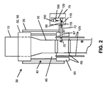
図2は、光学プリフォーム10が貫通している典型的な高温炉30の概略的な正面図を示している。図2に示されている炉30は、外側ジャケット35を有しているジャケット付き流体冷却式の炉30であり、これは、上部および下部の環状グラファイト接触部50、60を伴った加熱される内部45を有する主要加熱領域40を明らかにするために断面で示されている。円柱状製品、例えば光学プリフォーム10は、加熱の間、これらの接触部を通る。上部の接触部50および下部の接触部60は、それぞれ、環状壁55、65を有し、図2に示されているように、加熱される内部45の両端の近くに位置している。さらに、炉30は、加熱されたプリフォーム10が冷却し、固まり始める箇所に保護管125を有している。
FIG. 2 shows a schematic front view of a typical
引き続き図2を参照すると、炉30は、外部環境からの観察者が炉30内のプリフォーム10を見ることができる水平方向開口部70を有している。従って、水平方向開口部70は、炉30の加熱される内部45と連通しており、プリフォーム10は、この加熱される内部45を、加熱中に通過する。さらに、水平方向開口部70は、プリフォーム10の直径の測定が望まれる鉛直方向高さにある。これは例えば、図示の実施形態では、プリフォーム10の加熱が実質的に完了し、かつ、プリフォームの冷却が開始される直前またはまさにプリフォームの冷却が開始されようとしている場所である。より詳細には、水平方向開口部70は、下部の環状接触部60の環状壁65の開口部67を通って、ジャケット35の壁部を通って、さらに保護ブリッジ72を通っており、このようにして、水平方向開口部70は外部環境と連通もしている。
With continued reference to FIG. 2, the
この実施例の炉30は高温で作動し、自身にジャケットが付けられ、かつ、流体冷却式であるので、流体密封型の、流体冷却式ハウジング75を使用して、デジタルカメラ100およびそのレンズ105が収容および保護されている。実施例では、レンズ105は、広角レンズ(例えば、35mmフルサイズイメージセンサーの場合、焦点距離が35mm未満のレンズ)である。他の実施形態では、レンズ105は、通常のレンズまたは長焦点レンズであってもよい。ハウジング75は入口80を有しており、入口80が水平方向開口部70と位置合わせされ、プリフォーム10がハウジング75内から見えるように、炉30の外側に固定されている。
Since the
図3は、カメラ100と、レンズ105と、カメラ100およびレンズ105を収容し、保護するハウジング75と、を含んでいる、プリフォームの直径を測定するための装置の概略的な平面図を示している。図3にも、炉30の下部の接触部60と、カメラ100およびレンズ105を伴う保護ブリッジ72との相対的な位置合わせが示されており、これは、レンズ105と、炉30の内部の、下部の接触部60を通過するプリフォーム10との間のクリアーな視野(FOV、一対の点線で示されている)を可能にする。ミラー110は、この平面図ではカメラ100とレンズ105の真下にあるので見えない。
FIG. 3 shows a schematic plan view of an apparatus for measuring the diameter of a preform that includes a
上部の接触部50および下部の接触部60は、プリフォーム10を内部に有する炉30の内部45を加熱するために、電流を受け取り、伝導する、ということに留意されたい。接触部50、60が導電性であり、炉30の加熱機構の一部であるという事実は、下部の接触部60の壁部の開口部の大きさ(すなわち、高さおよび幅)に構造的および機能的制限がある、ということを意味する。
Note that the upper contact 50 and the
より信頼性の高い測定、並びに、より大きなプリフォームOD測定のためにより幅広い視野(例えば、図3のFOVを参照)を得るために、下部の接触部60を通る開口部の広がりが、炉30の加熱領域40における加熱の均一性に関して、幅広の開口部の効果を予測する数値モデルを用いて調査された。数値モデルおよびその結果は、以降で、実施例および図4A、図4Bおよび図4Cにおいて示される。開口部の幅を決定するために使用され得る例示的な数値モデルは有限要素法(FEM)であるが、他の数値モデルも考えられる。数値モデリングに基づいて、本明細書に開示された特定の実施形態では、開口部を約150mmまで、問題無く拡張することができることが決定された。他の実施形態では、開口部の最大幅は、約150mm未満であってもよく、または約150mmより大きくてもよい。当業者は、この開示に基づいて、数値モデリングによる開口部の最大幅の決定方法を理解するだろう。
In order to obtain a wider field of view (see, eg, FOV in FIG. 3) for more reliable measurements, as well as larger preform OD measurements, the extent of the opening through the
再び図2および図3を参照すると、透明な円柱状製品の直径を製造中に測定するための装置は、(A)レンズ105が取り付けられ、かつ、センシングおよびデジタル記録装置、例えば電荷結合素子(「CCD」)イメージセンサー(カメラの内側、図示されていない)を有するデジタルカメラ100と、(B)アルゴリズムがプログラムされたデジタルプロセッサ(それ自体は図示されていない)と、を含んでいる。他の実施形態では、センシングおよびデジタル記録装置は、相補型金属酸化膜半導体(CMOS)イメージセンサーであってもよい。より詳細には、カメラ100とレンズ105は、レンズ105が水平方向開口部70を通ってプリフォーム10製品の光学像を受け取ることを可能にするように配置されている。レンズ105はこの光学像をイメージセンサーに導き、イメージセンサーはこの光学像をデジタルイメージに変換し、プリフォーム10のデジタルイメージを記録する。
Referring again to FIGS. 2 and 3, an apparatus for measuring the diameter of a transparent cylindrical product during manufacture includes (A) a
この装置がさらに、炉30の水平方向開口部70とカメラ100のレンズ105との中間に配置されたミラー110のような反射器を備えてもよい。反射器は光学像を導き(図2の矢印115を参照)、この光学像は、炉30の水平方向開口部70およびハウジング75の入口80を介して、カメラ100のレンズ105で受け取られる。レンズ105とミラー110とが、図2に概略的に示すように、ハウジング75内の取り付けバー120に固定されていてもよい。
The apparatus may further comprise a reflector, such as a
デジタルカメラ100に加えて、装置はまた、イメージセンサーからのデジタルイメージにアクセスし、これを解釈し、円柱状製品の直径を決定し、報告するアルゴリズムがプログラムされたデジタルプロセッサを含む。適切なプロセッサおよびアルゴリズムには、現在知られているもの、および、将来、デジタルイメージを分析することができるものが含まれる。例示的なプロセッサおよびアルゴリズムを、本発明の方法に関連して、以降でさらに詳細に説明する。
In addition to the
プリフォーム10が冷却されて硬化された後、例えばプリフォーム10が保護管125から出ている炉30内の位置、例えば図2の位置Bで、プリフォーム10の第2の測定を行うことが望ましい場合がある。特定の特徴は図2には示されていないが、第2のプリフォーム測定が位置Bで行われるべき場合、炉30は、外部環境から、保護管125から出ている冷却中のプリフォームを見ることができるように、位置Bに別の水平方向開口部を有するだろう。また、これと並んで、位置Bで冷却中のプリフォーム10を測定するための第2の装置を有するだろう。これは、それ自身のセンシングおよびデジタル記録装置およびレンズを有している別のカメラおよび別の流体冷却式ハウジングを含んでいる。これらの全ての特徴は、プリフォーム10が炉30の下部の接触部60を通過するメイン測定位置、すなわち位置Aに関連して上述したものと同じであってもよい。
After the
別の一般的な実施形態では、本発明は、透明な円柱状製品の直径を、円柱状製品を見ることができる水平方向開口部を有する高温炉内での製造中に測定するための方法を提供する。この方法は、以下の基本ステップを含んでいる。すなわち、(A)レンズが取り付けられているカメラを用いて、水平方向開口部を通して放出された、円柱状製品の光学像を受け取るステップと、(B)この光学像をセンシングおよびデジタル記録装置に導くステップと、(C)センシングおよびデジタル記録装置を用いて、光学像をデジタルイメージに変換し、このデジタルイメージを記録するステップと、(D)アルゴリズムがプログラムされたプロセッサを用いて、このデジタルイメージを解釈し、円柱状製品の直径を決定するステップと、を含んでいる。 In another general embodiment, the present invention provides a method for measuring the diameter of a transparent cylindrical product during manufacture in a high temperature furnace having a horizontal opening through which the cylindrical product can be viewed. provide. This method includes the following basic steps: (A) receiving an optical image of a cylindrical product emitted through a horizontal opening using a camera to which a lens is attached; and (B) guiding the optical image to a sensing and digital recording device. (C) converting the optical image into a digital image using a sensing and digital recording device and recording the digital image; and (D) using a processor programmed with the algorithm, Interpreting and determining the diameter of the cylindrical product.
再び、図2および図3に示されている装置を手短に参照すると、炉30の水平方向開口部70を通して放出された、円柱状製品(例えばプリフォーム10)の光学像115は、カメラ100およびレンズ105によって受け取られる。レンズ105が相応に取り付けられ、かつ、調整されているカメラ100の内部では、当業者によって容易に理解されるように、光学像115が、カメラ内部のセンシングおよびデジタル記録装置(図示されていない)に導かれる。センシングおよびデジタル記録装置はその後、この光学像をデジタルイメージに変換し、この光学像は記録される。例えば、カメラ100の一部であってもよい、または、別個のマイクロプロセッサであってもよい、または、コンピュータの一部であってもよい、アルゴリズムがプログラムされたプロセッサ(図示されていない)が、デジタルイメージを解釈して、円柱状製品(プリフォーム10)の直径並びに他の特性を決定する。これは、円柱状製品(プリフォーム10)の中心の位置と、プリフォーム10のコアロッド15(図1を参照)内の任意のジョイントの存在および位置を含むが、これに限定されない。
Again, referring briefly to the apparatus shown in FIGS. 2 and 3, the
デジタルイメージを解釈して、円柱状製品の直径を決定する最後のステップ(D)は、アルゴリズムがプログラムされたプロセッサの使用を必要とする。このプロセッサは、例えば、コンピュータ、プロセス制御装置およびシステムが統合されたコンピュータ構成要素、スタンドアローンマイクロプロセッサ、または、現在、当業者に既知であるまたは将来、当業者に知られるようになる、ここで詳細に説明されるアルゴリズムを実行することができるあらゆる他のプログラミング可能なプロセッサであってよいが、これに制限されない。 The final step (D) of interpreting the digital image and determining the diameter of the cylindrical product requires the use of a processor programmed with the algorithm. This processor may be, for example, a computer, a computer component with integrated process controller and system, a stand-alone microprocessor, or now known to those skilled in the art or will become known to those skilled in the art in the future. Any other programmable processor capable of executing the algorithm described in detail may be, but is not limited to.
一般的に、このアルゴリズムは、(1)デジタルイメージを切り取って、より小さい、切り取られたデジタルイメージを生成するステップと、(2)切り取られたデジタルイメージから勾配フィルタリングされたイメージを生成するステップと、(3)複数の勾配ラインスキャンを実行し、複数の勾配ラインスキャンを総計して、グレーレベル勾配スペクトルを形成するステップと、(4)グレーレベル勾配スペクトル内の複数のピークのうちのどれが、プリフォームの真の左側縁および真の右側縁を表すのかを識別するステップと、(5)プリフォームの真の左側縁の値と真の右側縁の値とを用いてプリフォームの外径を計算するステップと、(6)プリフォームの外径を報告するステップと、を含んでいる。これらのステップのそれぞれを、ここで、さらに詳細に説明する。アルゴリズムのステップ(1)〜(4)から得られたサンプルイメージとスペクトルとが図5に示されている。 In general, the algorithm includes (1) cropping a digital image to produce a smaller, cropped digital image; and (2) creating a gradient filtered image from the cropped digital image. (3) performing a plurality of gradient line scans and summing the plurality of gradient line scans to form a gray level gradient spectrum; and (4) any of the plurality of peaks in the gray level gradient spectrum. Identifying whether to represent the true left edge and the true right edge of the preform; and (5) the preform outer diameter using the true left edge value and the true right edge value of the preform. And (6) reporting the outer diameter of the preform. Each of these steps will now be described in more detail. A sample image and spectrum obtained from steps (1) to (4) of the algorithm are shown in FIG.
アルゴリズムの第1のステップでは、デジタルイメージが切り取られ、周囲の暗い空間が除去され、より小さい、切り取られたデジタルイメージが生成される(図5の「RAWイメージ」(1)を参照)。この、より小さい、切り取られたイメージ(1)は、炉の水平方向開口部を通して見ることができる明るい視野のみを含む。 In the first step of the algorithm, the digital image is cropped and the surrounding dark space is removed to produce a smaller, cropped digital image (see “RAW Image” (1) in FIG. 5). This smaller, cropped image (1) contains only a bright field of view that can be seen through the horizontal opening of the furnace.
アルゴリズムの第2のステップでは、切り取られたデジタルイメージ(1)に標準偏差フィルターを適用することによって、勾配フィルタリングされたイメージ(2)(図5における「勾配フィルタリングされたイメージ」(2)を参照)が生成される。標準偏差フィルターは、勾配フィルタリングされたイメージ(2)の各画素が、切り取られたデジタルイメージ(1)の対応する画素の周辺領域内の画素の標準偏差に等しい、勾配フィルタリングされたイメージ(2)を作成することによって動作する。切り取られたデジタルイメージ(1)の画素の標準偏差は、周辺領域が明から暗にシフトするところ、または暗から明にシフトするところで最も高くなるので、切り取られたデジタルイメージ(1)内で縁を検出するために、勾配フィルタリングされたイメージ(2)が使用される。 In the second step of the algorithm, the gradient filtered image (2) (see “Gradient filtered image” (2) in FIG. 5) by applying a standard deviation filter to the cropped digital image (1). ) Is generated. The standard deviation filter is a gradient filtered image (2) where each pixel of the gradient filtered image (2) is equal to the standard deviation of the pixels in the peripheral region of the corresponding pixel of the cropped digital image (1). Works by creating. The standard deviation of the pixels of the cropped digital image (1) is highest where the surrounding area shifts from light to dark, or from dark to light, so the edges in the cropped digital image (1) The gradient filtered image (2) is used to detect.
アルゴリズムの第3のステップでは、勾配フィルタリングされたイメージ(2)の複数のラインスキャンが収集され、まとめられて、グレーレベル勾配スペクトルが形成される(図5の「グレーレベル勾配スペクトル」(3)を参照)。いくつかの実施形態では、1つのラインスキャンだけが収集され得るが、グレーレベル勾配スペクトル(3)は、複数のラインスキャンの総計を含む場合に、改善された信号対雑音比を有し得る。ある実施例では、グレーレベル勾配スペクトル(3)は、約40〜50のラインスキャンの総計を含む。他の実施形態では、グレーレベル勾配スペクトル(3)は、50を超えるラインスキャンまたは40未満のラインスキャンを含み得る。より詳細には、複数の勾配ラインは、勾配フィルタリングされたイメージ(2)の鉛直中心の近くに位置するスキャン領域内でスキャンされ、勾配フィルタリングされたイメージの全幅の少なくとも一部を横切って水平に延びる。すなわち、測定されるプリフォームの全幅を十分に包囲する(スキャン領域のおおよその位置を見るための図6のRAWイメージ内の白線140を参照)。各ラインスキャンは、勾配フィルタリングされたイメージ(2)のスキャン領域内で水平スキャンライン位置を選択し、設定された水平スキャンライン位置に沿ってイメージのグレーレベルを記録することによって実行される(例えば、図5における「1つの勾配スキャンライン」(pre−3)を参照)。勾配フィルタリングされたイメージ(2)の複数のラインスキャンを収集し、総計した後、グレーレベル勾配スペクトルイメージ(3)は、複数の左側ピーク145、複数の右側ピーク150、および、複数のマイナーバックグラウンドピーク155a、155b、155cを有する(再度、図5におけるスペクトル(3)を参照)。いくつかの実施形態では、グレーレベル勾配スペクトルイメージ(3)は、唯一の左側ピーク、唯一の右側ピーク、および/または、1つのマイナーバックグラウンドピークを有していてもよい、または、マイナーバックグラウンドピークを有していなくてもよい。左側ピーク145および右側ピーク150は、自身の中にそれぞれ、プリフォームの真の左側縁および真の右側縁を含む。マイナーバックグラウンドピーク155a、155b、155cは、複雑なライトバックグラウンド並びにバックグラウンドグラファイト要素の表面状態から生じるノイズを表す。「マイナー」とは、これらのバックグラウンドピーク155a、155b、155cが、対象の左側ピークおよび右側ピークよりも一般的に、より短いまたはより小さいことを意味し、プリフォームの直径を測定するときに考慮される必要がない、ということを意味する。
In the third step of the algorithm, multiple line scans of the gradient filtered image (2) are collected and combined to form a gray level gradient spectrum (“Gray Level Gradient Spectrum” (3) in FIG. 5). See). In some embodiments, only one line scan may be collected, but the gray level gradient spectrum (3) may have an improved signal to noise ratio when it includes the sum of multiple line scans. In one embodiment, the gray level gradient spectrum (3) includes a total of about 40-50 line scans. In other embodiments, the gray level gradient spectrum (3) may include more than 50 line scans or less than 40 line scans. More particularly, the plurality of gradient lines are scanned within a scan region located near the vertical center of the gradient filtered image (2) and horizontally across at least a portion of the full width of the gradient filtered image. Extend. That is, it fully surrounds the entire width of the preform to be measured (see
アルゴリズムの第4のステップでは、グレーレベル勾配スペクトル(3)における複数の左側ピーク145および複数の右側ピーク150の中から、プリフォームの真の左側縁および真の右側縁が識別される。ここで図7を参照すると、複数の左側ピーク145を含んでいるグレーレベル勾配スペクトル上の左側ピークウィンドウ領域160を選択することによって、グレーレベル勾配スペクトル分析(4)が実行される。同様に、右側ピークウィンドウ領域165も、複数の右側ピーク150を含んでいるグレーレベル勾配スペクトル上で選択される。これらの選択は、各ウィンドウ領域の外側のマイナーバックグラウンドピーク155a、155b、155cを選択されないままにし、これらに、以下で説明される別個の分析が施される。左側ピークウィンドウ領域160は、複数の左側ピーク145のうちの最も高い左側ピークにセンタリングされるべきであり、同様に、右側ピークウィンドウ領域165は、複数の右側ピーク150のうちの最も高い右側ピークにセンタリングされるべきである。
In the fourth step of the algorithm, the true left edge and the true right edge of the preform are identified among the plurality of
グレーレベル勾配スペクトル(3)からのプリフォームの真の左側縁および真の右側縁の識別(ステップ(4)、図7)は、さらに、さらなる分析から、マイナーバックグラウンドピークを除去するために、ピーク検出のためのベースラインを確立することを含む。これは、まずは、マイナーバックグラウンドピーク155cの一部分をダイナミックにサンプリングし、次に、このダイナミックサンプリングの結果に基づいてノイズ・フロア・レベルを計算することによって実行される。その後、ベースラインが、このノイズ・フロア・レベルに所定の閾値量を加えることによって導出される。その後、このベースラインを下回るあらゆるピークが、処理および分析の目的に対して、無視される。この閾値量は、グレーレベル勾配スペクトル(3)の選択されたウィンドウの最大ピーク高さから、ノイズ・フロア・レベルを減算し、次に、結果として生じた高さを所定のファクターで除算することによって決定される。ここでこのファクターは、図7のピークEのような、識別されたノイズピークを除去するのに十分な大きさを有しているが、図7のピークDのような、可能性のある、真の縁ピークを除去するのには十分でない。ある実施例では、このファクターは約3であってよい。択一的な実施形態では、所定の閾値量は、例えば、ダイナミックにサンプリングされた、マイナーバックグラウンドピークの一部分の平均的な高さに0.5を乗算することによって決定され得る。
Identification of the true left and true right edges of the preform from the gray level gradient spectrum (3) (step (4), FIG. 7) can be further performed to remove minor background peaks from further analysis. Including establishing a baseline for peak detection. This is performed by first dynamically sampling a portion of the
アルゴリズムによるさらなる考慮からマイナーバックグラウンドピーク(ノイズおよび散乱データ)を除去した後、プリフォームの真の左側縁および真の右側縁の位置に対する数値がそれぞれ得られる。最初に、ターゲット左側ピークおよびターゲット右側ピークがそれぞれ識別される。ここで図7を参照すると、右側ピークウィンドウ領域165内の複数の右側ピーク150(いずれもベースラインより高い)が分析され、右側ピークウィンドウ領域165において最も右側に位置するピーク(ピークD)が、ターゲット右側ピークに選択される。ターゲット右側ピークの位置は、プリフォームの真の右側縁に等しい数値として記録される。図示されていないが、左側ピークウィンドウ領域160内の複数の左側ピーク145(同様に、いずれもベースラインより高い)に同じ分析および選択手順が適用され、ターゲット左側ピークの位置が、プリフォームの真の左側縁に等しい数値として記録される。引き続き図7を参照すると、先の分析手順により、マイナーバックグラウンドピーク155a、155b、155cが、ウィンドウ領域160、165において除外可能である。図7に示されているグレーレベル勾配スペクトル分析(4)については、ピークAおよびEはベースラインによって除去され、ピークB、CおよびDがピークの候補として残される。次いで、ピークDが、右側ピークウィンドウ領域165内の最も右の位置にある自身の位置によって、ターゲット右側ピークとして識別される。
After removing minor background peaks (noise and scatter data) from further consideration by the algorithm, numerical values are obtained for the positions of the true left and true right edges of the preform, respectively. Initially, a target left peak and a target right peak are each identified. Referring now to FIG. 7, a plurality of right peaks 150 (all higher than the baseline) in the right
最後に、プリフォームの真の左側縁の値と真の右側縁の値との間の差を求め、その差の絶対値を取ることによって、プリフォームの外径(OD)が計算される。次に、プリフォームの外径ODが報告されるか、または、さらなる分析および決定の対象にされ得る。 Finally, the outer diameter (OD) of the preform is calculated by taking the difference between the true left edge value and the true right edge value of the preform and taking the absolute value of the difference. Next, the outer diameter OD of the preform can be reported or subjected to further analysis and determination.
センシングおよびデジタル記録装置によって光学像が取得され、デジタルイメージに変換された後に、アルゴリズムの残りのステップを続ける前に炉が動作していることを確認するためにチェックを行うことが可能であり、かつ、望ましい場合がある。例えば、任意選択的に、切り取られたデジタルイメージにおける平均グレーレベルがプロセッサによって計算されてもよく、これが所定の閾値未満である場合に、アルゴリズムの実行を停止する。この所定の閾値は、使用されるグレースケールに基づいて選択され、かつ、十分に低い値であるべきであり、これによって、切り取られたデジタルイメージにおける平均グレーレベルがこの閾値以下である場合には、炉が動作していないと仮定するのが妥当であると、当業者は考える。より詳細には、動作中でないことが確認されている間にカメラからの炉のイメージを収集し、このイメージの全画素の平均グレーレベルを決定することによって所定の閾値が決定されてもよい。イメージが8ビットグレースケール画像(すなわち、256階調のグレー)である実施例では、動作していない間の炉の平均グレーレベルは8以下であってよい。所定の閾値は、炉の設計および特定の用途に基づいて、実施形態ごとに異なるだろう。 After the optical image is acquired by the sensing and digital recording device and converted to a digital image, a check can be made to ensure that the furnace is operating before continuing the remaining steps of the algorithm, And sometimes it is desirable. For example, optionally, the average gray level in the cropped digital image may be calculated by the processor, and if this is below a predetermined threshold, execution of the algorithm is stopped. This predetermined threshold is selected based on the grayscale used and should be sufficiently low so that if the average gray level in the cropped digital image is below this threshold Those skilled in the art will consider it reasonable to assume that the furnace is not operating. More particularly, the predetermined threshold may be determined by collecting an image of the furnace from the camera while it is determined not to be in operation and determining the average gray level of all pixels of this image. In embodiments where the image is an 8-bit grayscale image (ie, 256 shades of gray), the average gray level of the furnace during non-operation may be 8 or less. The predetermined threshold will vary from embodiment to embodiment based on the furnace design and the specific application.
いくつかの実施形態では、プリフォーム外径ODが成長して、一定のサイズに達すると、プリフォームの中央領域にマスク(図示されていない)が適用され、ピークの固定を混乱させる界面欠陥/泡が回避される。その後で、プリフォーム外径ODがもはや迅速にサイズを変えることがないスタートアップ滴下段階をプリフォームが通過すると、マスクが作動されてよい。従って、左側縁および右側縁はそれぞれ、自身の最後の20の位置について追跡される。これらの位置の(最大−最小)が、縁の各側について計算される。これらの位置の(最大−最小)が両方のガラス縁に対して、一定の閾値未満である場合、これは、ガラス外径ODが十分な安定に達したことを意味する。従って、マスクインジケータが、0から1に更新される。次のループから始めて、プログラムがインジケータ=1を確認すると、これはこのマスクを開き、このマスクの外の領域に対してのみ、イメージ水平勾配をスキャンする。しかし、線引きの最終段階では、プリフォーム外径ODは再び小さくなる。そのため、この時点では、マスクは無効にされるべきである。マスクインジケータ=1であり、かつ、プリフォーム外径ODが一定の閾値よりも小さいことを確認することによって、無効化点が決定されてもよい。 In some embodiments, when the preform outer diameter OD grows and reaches a certain size, a mask (not shown) is applied to the central region of the preform, causing interface defects / Bubbles are avoided. Thereafter, the mask may be activated when the preform passes through a start-up dripping phase where the preform outer diameter OD no longer changes size quickly. Thus, the left and right edges are each tracked for their last 20 positions. The (maximum-minimum) of these positions is calculated for each side of the edge. If the (max-min) of these positions is below a certain threshold for both glass edges, this means that the glass outer diameter OD has reached sufficient stability. Accordingly, the mask indicator is updated from 0 to 1. Starting with the next loop, when the program sees indicator = 1, it opens this mask and scans the image horizontal gradient only for areas outside this mask. However, at the final stage of drawing, the preform outer diameter OD becomes smaller again. Therefore, at this point, the mask should be disabled. The invalidation point may be determined by confirming that the mask indicator = 1 and the preform outer diameter OD is smaller than a certain threshold value.
外径OD計算のために2つのガラス縁が識別されると、別の有用な情報である、プリフォームの中心位置を直ちに導出することができる。その計算式は簡単である。
プリフォーム中心位置=左側縁の位置+OD/2
Once the two glass edges are identified for the outer diameter OD calculation, another useful information, the center position of the preform, can be derived immediately. The calculation formula is simple.
Preform center position = left edge position + OD / 2
この情報は、szugオペレータがプリフォームのたわみを改善するのに極めて有用であり得る。中心位置の変動幅が一定の閾値を超えるのをオペレータが確認すると、オペレータは、中心位置の変動を低減させ、従って潜在的なたわみ形状を矯正するために、プリフォームに対して「たわみバー(bow−bar)」を使用し始めるだろう。 This information can be extremely useful for the szug operator to improve preform deflection. When the operator confirms that the variation width of the center position exceeds a certain threshold, the operator reduces the variation of the center position, and thus corrects the potential deflection shape with a “deflection bar ( would start using "bow-bar)".
図8、図9および図10は、上述した装置およびデジタルイメージを用いた、共通のコアジョイント検出のためのアルゴリズムの説明を容易にするために提供されている。カメラ100によって生成されたデジタルカメライメージによって、本発明の方法および装置を使用して、コアロッド間のジョイントまたは最初のコアロッドの先端も、オンラインで識別することができる。このようなジョイント識別は、グレーレベル勾配スペクトルの生成(図5(3)および図8(A)を参照)の後、グレーレベル勾配スペクトル(A)における複数の左側ピーク145と複数の右側ピーク150との中間に位置する複数の中間ピーク185が存在するか否かを決定する第1のステップを含む。これは次のことによって行われる。すなわち、(a)複数の左側ピーク145および複数の右側ピーク150(図5(3))の中間の中央ウィンドウ領域190を選択すること、(b)中央ウィンドウ領域190に対する統合領域を計算すること、および、(c)ジョイントが存在するか否かを決定するために、この統合領域を分析すること、によって行われる。統合領域がジョイントを示すのに十分な値を有したときを主観的に識別するオペレータによる目視検査によって、この統合領域が分析されてよい。他の実施形態では、アプリケーションごとに異なり得る所定の値を統合領域が超えたときを決定するために、統合領域が自動的に分析されてよい。統合領域が統合閾値を超えると、明確なジョイント信号Jが存在する。図8(B)および(C)を参照。これは次に、コアロッドのジョイントの大きさを決定するために、複数の左側ピークおよび複数の右側ピークに関連して上述したように、分析され得る。
8, 9 and 10 are provided to facilitate the description of the algorithm for common core joint detection using the apparatus and digital image described above. With the digital camera image generated by the
最初のコアジョイントの検出は、プリフォーム製造プロセスのスタートアップ制御に重要なものであり得る。しかし、第1のコアジョイントは、しばしば溶接特徴によって干渉される(図9を参照)。これはグレーレベル勾配スペクトル内に、混乱をもたらす溶接ピーク195を生成する。最初のコアジョイントを表すこのような溶接ピーク195は、コアロッド内の後続のジョイントと比較して、より細長く延びることがある。従って、最初のコアジョイントをより良く捕らえる、より洗練されたアルゴリズムも開発されている。図9は、この新しい「J幅信号」(2)と上述した「J信号」(1)との比較を提示する。 The detection of the initial core joint can be important for start-up control of the preform manufacturing process. However, the first core joint is often interfered by welding features (see FIG. 9). This creates a confusing weld peak 195 in the gray level gradient spectrum. Such a weld peak 195 representing the first core joint may extend more elongated compared to subsequent joints in the core rod. Therefore, more sophisticated algorithms have been developed that better capture the first core joint. FIG. 9 presents a comparison between this new “J width signal” (2) and the “J signal” (1) described above.
例えば、プリフォーム10内にジョイントが存在することが決定されると、グレーレベル勾配スペクトルが分析され、このジョイントのサイズおよび位置が決定される。上述した、プリフォームの真の左側縁および右側縁を決定するための方法(アルゴリズムステップ(4))と同様に、図10に示されているように、中央領域ウィンドウ190が、グレーレベル勾配スペクトルにおいて、複数の左側ピーク145と複数の右側ピーク150の中間に選択される。中央領域ウィンドウ190は、ジョイントの左側縁および右側縁(それ自体は図示されていない)を含む、ジョイントの位置を表す複数の中間ピーク200を含んでいる。次に、ピーク検出のためのベースラインが確立されて、アルゴリズムステップ(4)について上述したように、さらなる分析から、マイナーバックグラウンドピークが除去される。その後、ジョイントの真の左側縁と真の右側縁の位置に対する数値がそれぞれ得られ得る。最も外側の左側ピークと最も外側の右側ピークとがそれぞれ、中央ウィンドウ領域190内の複数の中間ピーク200の中から識別され、それらの値がそれぞれ、ジョイントの真の左側縁および真の右側縁の位置として割り当てられる。次に、ジョイントの真の左側縁の値と真の右側縁の値との間の差を見出すことによって、プリフォームの幅(直径)について上述したように、ジョイント幅が計算されてよい。次に、このジョイント幅が報告されるか、または、さらなる分析および決定の対象にされ得る。さらに、ジョイントの中心位置を、以下の式を使用して決定することができる。
ジョイントの中心位置=ジョイントの左側縁の位置+(ジョイント幅)/2
For example, if it is determined that there is a joint in the
Joint center position = left edge position of the joint + (joint width) / 2
付加的に、想定されたコアジョイントに関する値を報告する前に、検証ステップを実行することができ、ここでは、ジョイントの中心位置がプリフォームの中心から離れすぎている場合には(閾値化)、検出された特徴が、実際にはコアジョイントでないことが想定され、縁の位置またはこの特徴の幅は報告されない。 Additionally, a verification step can be performed before reporting values for the assumed core joint, where the joint center position is too far from the preform center (thresholding). It is assumed that the detected feature is not actually a core joint and the edge position or width of this feature is not reported.
本発明および上述した、本発明の様々な実施形態は、以下の例を参照することにより、より良く理解されるであろう。これらの例は、実行されている本発明の特定の実施形態に過ぎず、本発明の装置または方法の範囲を決して限定するものではない。 The invention and the various embodiments of the invention described above will be better understood with reference to the following examples. These examples are only specific embodiments of the present invention being performed and are in no way intended to limit the scope of the apparatus or method of the present invention.
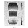
下部の接触部における、許容可能な最も幅の広い開口部の決定
初期段階では、下部の接触部60の壁部65を通る開口部は130mmであった。この幅は、以前使用されていたテレセントリックレーザスキャン方法には十分であったが、約130mmよりも大きい直径を有するプリフォームを測定するのには十分ではなかった。拡張された開口部が、加熱領域40全体にわたって、炉の温度および均一性に、許容可能ではない影響を与えるであろう幅を推定するために、数値モデルが使用された。加熱領域40内で得られる加熱パターンを示した数値モデル化の、図によって表された結果が、図4A、図4Bおよび図4Cに提示されている。より具体的には、図4Aは、130mmの最初の開口部67による、許容可能に均一な加熱パターンを示している。図4Bも、150mmに拡張された開口部67が依然として、均一かつ許容可能な加熱パターンを生成することを示している。しかし、開口部67を180mmに拡張すると、数値モデルは、図4Cに示されているように、加熱領域40が許容可能ではない程度まで不均一に加熱されるであろうことを予測した。
In the initial stage of determining the widest allowable opening at the lower contact, the opening through the
装置の性能とアルゴリズム
使用されたカメラ機器:Allied Vision Technologies社の「Guppy」5メガピクセル(MP)カメラ、モデル F−503B。
Equipment performance and algorithm Camera equipment used: “Guppy” 5 megapixel (MP) camera from Allied Vision Technologies, model F-503B.
ソフトウェア:Allied Vision Technologies社の標準Firepackage v 3.1を使用して、カメラからのイメージを捕らえた。この機能に対しては、他の市販の、または注文で作られたプログラムも使用することができることに留意されたい。 Software: Allied Vision Technologies standard Firepackage v 3.1 was used to capture images from the camera. Note that other commercially available or custom-made programs can be used for this function.
レンズ:Edmund Optics社の16mm固定焦点距離MPレンズ。用いられた焦点距離は、所望の視野(FOV)およびレンズとターゲットプリフォームとの間の距離に依存した。この使用ケースには16mmが適切であった。 Lens: 16 mm fixed focal length MP lens from Edmund Optics. The focal length used was dependent on the desired field of view (FOV) and the distance between the lens and the target preform. 16 mm was appropriate for this use case.
フィルター:(a)強い炉の光を減衰させるための、複数のニュートラルデンシティフィルター。様々な光学密度を含む、この種のフィルターの異なる組み合わせが、上部対下部位置で使用された。(b)ガラス縁とグラファイトバックグラウンド(すなわち、下部の接触部の内面と下部の保護管)との間のグレースケールイメージコントラストを増加させるための赤色カラーフィルター。(c)測定を妨げるガラス表面からの不所望な反射を除去するために、直線偏光フィルターが使用された。 Filter: (a) Multiple neutral density filters to attenuate strong furnace light. Different combinations of this type of filter, including various optical densities, were used in the top versus bottom position. (B) A red color filter to increase the gray scale image contrast between the glass edge and the graphite background (ie, the inner surface of the lower contact and the lower protective tube). (C) A linear polarizing filter was used to remove unwanted reflections from the glass surface that interfered with the measurement.
Claims (22)
(A)デジタルカメラと、
(B)デジタルプロセッサと、
を含んでおり、
前記デジタルカメラは、レンズが取り付けられており、かつ、センシングおよびデジタル記録装置を有し、前記レンズは、前記炉の壁部の前記開口部を通じて、前記円柱状製品の光学像を受け取り、前記光学像を前記センシングおよびデジタル記録装置に導き、前記センシングおよびデジタル記録装置は、前記光学像をデジタルイメージに変換し、前記デジタルイメージを記録し、
前記デジタルプロセッサは、アルゴリズムがプログラムされ、前記アルゴリズムは、前記センシングおよびデジタル記録装置からの前記デジタルイメージにアクセスして、前記デジタルイメージを解釈し、前記円柱状製品の測定値を決定し、報告し、
前記アルゴリズムは、以降のステップ(1)〜(6)を含んでおり、すなわち、
(1)前記デジタルイメージを切り取って、周囲の暗い空間を除去し、前記炉の前記水平方向開口部を通して見ることができた明るい視野のみを含んでいる、所定の高さおよび幅を有している、より小さい、切り取られたデジタルイメージを生成するステップを含んでおり、
(2)前記切り取られたデジタルイメージから、標準偏差フィルターを用いて勾配フィルタリングされたイメージを生成するステップを含んでおり、
(3)複数のラインスキャンを実行し、複数のラインスキャンを総計して、1つまたは複数の左側ピークと、1つまたは複数の右側ピークと、1つまたは複数のマイナーバックグラウンドピークと、を有しているグレーレベル勾配スペクトルを形成するステップを含んでおり、ここで、前記複数のラインスキャンは、前記勾配フィルタリングされたイメージの鉛直中心の近くに位置するスキャン領域内に存在し、かつ、前記勾配フィルタリングされたイメージの全幅にわたって水平に延在し、
(4)以降のステップ(a)〜(c)を実行することによって、前記グレーレベル勾配スペクトル内の前記1つまたは複数の左側ピークおよび前記1つまたは複数の右側ピークのうちのどれが、前記円柱状製品の真の左側縁および真の右側縁を表すのかを識別するステップを含んでおり、
(a)前記グレーレベル勾配スペクトル上で、前記複数の左側ピークを含んでいる左側ピークウィンドウ領域を選択し、前記複数の右側ピークを含んでいる右側ピークウィンドウ領域を選択し、各ウィンドウ領域の外側にある前記マイナーバックグラウンドピークを、別個の分析のために残すステップ、
(b)以降の(i)〜(iii)によって、さらなる分析から、前記マイナーバックグラウンドピークを除去する、ピーク検出のためのベースラインを確立するステップ、
(i)前記マイナーバックグラウンドピークの一部分をダイナミックにサンプリングし、前記ダイナミックサンプリングに基づいてノイズ・フロア・レベルを計算すること、
(ii)前記ノイズ・フロア・レベルに閾値を加えることによってベースラインを決定すること、
(iii)その後、前記ベースラインを下回るあらゆるピークを無視すること、
(c)それぞれ以降の(i)、(ii)によって、前記円柱状製品の前記真の左側縁の位置と真の右側縁の位置に対する数値を提供するために、ターゲット左側ピークとターゲット右側ピークを識別するステップ、
(i)前記左側ピークウィンドウ領域において、前記ベースラインよりも高い前記複数の左側ピークをそれぞれ分析し、前記左側ピークウィンドウ領域において最も左側に位置する前記ターゲット左側ピークを選択し、前記円柱状製品の前記真の左側縁に等しい数値として前記ターゲット左側ピークの位置を記録すること、
(ii)前記右側ピークウィンドウ領域において、前記ベースラインよりも高い前記複数の右側ピークをそれぞれ分析し、前記右側ピークウィンドウ領域において最も右側に位置する前記ターゲット右側ピークを選択し、前記円柱状製品の前記真の右側縁に等しい数値として前記ターゲット右側ピークの位置を記録すること、
(5)前記円柱状製品の前記真の左側縁の値と前記真の右側縁の値との間の差の絶対値を取ることによって、前記円柱状製品の外径を計算するステップを含んでおり、
(6)前記円柱状製品の前記外径を報告するステップを含んでいる、
装置。 An apparatus for measuring a transparent cylindrical product during manufacture in a high temperature furnace having a horizontal opening through which the cylindrical product can be seen, the apparatus comprising:
(A) a digital camera;
(B) a digital processor;
Contains
The digital camera has a lens attached and has a sensing and digital recording device, and the lens receives an optical image of the cylindrical product through the opening in the furnace wall, and the optical camera Directing an image to the sensing and digital recording device, wherein the sensing and digital recording device converts the optical image into a digital image, records the digital image,
The digital processor algorithm is a program, the algorithm is to the access digital image from the sensing and digital recording device, the interpreting a digital image, to determine a measure of the cylindrical product, and report ,
The algorithm includes the following steps (1) to (6):
(1) Cut out the digital image to remove the dark surroundings and have a predetermined height and width, including only the bright field that could be seen through the horizontal opening of the furnace. Generating a smaller, cropped digital image that includes:
(2) generating a gradient filtered image from the cut digital image using a standard deviation filter;
(3) Perform multiple line scans and aggregate the multiple line scans to obtain one or more left peaks, one or more right peaks, and one or more minor background peaks. Forming a gray level gradient spectrum having the plurality of line scans present in a scan region located near a vertical center of the gradient filtered image; and Extends horizontally across the entire width of the gradient filtered image;
(4) By performing the following steps (a) to (c), which one of the one or more left peaks and the one or more right peaks in the gray level gradient spectrum is Identifying whether it represents the true left edge and the true right edge of the cylindrical product,
(A) selecting a left peak window region including the plurality of left peaks on the gray level gradient spectrum; selecting a right peak window region including the plurality of right peaks; Leaving the minor background peak at for separate analysis;
(B) establishing a baseline for peak detection that removes the minor background peak from further analysis according to (i) to (iii) below;
(I) dynamically sampling a portion of the minor background peak and calculating a noise floor level based on the dynamic sampling;
(Ii) determining a baseline by adding a threshold to the noise floor level;
(Iii) then ignoring any peaks below the baseline;
(C) Subsequent to (i) and (ii) respectively, the target left peak and the target right peak are provided to provide numerical values for the true left edge position and the true right edge position of the cylindrical product. Identifying step,
(I) analyzing the plurality of left peaks higher than the baseline in the left peak window region, selecting the target left peak located on the leftmost side in the left peak window region; and Recording the position of the target left peak as a value equal to the true left edge;
(Ii) analyzing each of the plurality of right peaks higher than the baseline in the right peak window region, selecting the target right peak located on the rightmost side in the right peak window region; and Recording the position of the target right peak as a value equal to the true right edge;
(5) calculating the outer diameter of the cylindrical product by taking the absolute value of the difference between the true left edge value and the true right edge value of the cylindrical product. And
(6) reporting the outer diameter of the cylindrical product;
apparatus.
請求項1記載の装置。 The transparent cylindrical product is an optical fiber preform comprising two or more layers of vitreous material;
The apparatus of claim 1.
前記コア層の屈折率は、前記クラッド層の屈折率よりも高い、
請求項2記載の装置。 The preform includes a core layer having a predetermined refractive index, and a cladding layer having a predetermined refractive index and surrounding an inner layer,
The refractive index of the core layer is higher than the refractive index of the cladding layer,
The apparatus of claim 2.
請求項1記載の装置。 The sensing and digital recording device includes a charge coupled device (“CCD”) image sensor,
The apparatus of claim 1.
請求項1記載の装置。 The measured value includes the diameter of the cylindrical product,
The apparatus of claim 1.
請求項1記載の装置。 The camera is enclosed in a fluid-tight and fluid-cooled housing that is aligned with the opening in the furnace wall for passing the optical image of the cylindrical product. Have an entrance,
The apparatus of claim 1.
請求項6記載の装置。 Further comprising a reflector for directing the optical image received through the opening in the furnace wall and the inlet of the fluid cooled housing to the lens of the camera;
The apparatus of claim 6 .
前記炉は、加熱されている間に前記円柱状製品が通過する上部および下部の環状グラファイト接触部を伴った加熱される内部を有しており、前記上部および下部の接触部は、それぞれ環状壁を有しており、かつ、前記加熱される内部の両端の近くに位置しており、
前記炉は、前記上部の環状グラファイト接触部の前記環状壁を通る前記円柱状製品を見ることができる前記水平方向開口部の少なくとも一部を有しており、前記上部および下部の接触部は、内部に前記円柱状製品を有する前記グラファイト炉の内部を加熱するために、電流を受け取り、伝導する、
請求項1記載の装置。 The furnace is a jacketed fluid cooled graphite furnace,
The furnace has a heated interior with upper and lower annular graphite contacts through which the columnar product passes while being heated, the upper and lower contacts being respectively annular walls And is located near both ends of the heated interior,
The furnace has at least a portion of the horizontal opening through which the cylindrical product through the annular wall of the upper annular graphite contact can be seen, the upper and lower contact portions being Receiving and conducting current to heat the interior of the graphite furnace having the cylindrical product therein;
The apparatus of claim 1.
(A)レンズが取り付けられているカメラを用いて、前記水平方向開口部を通して放出された、前記円柱状製品の光学像を受け取るステップと、
(B)前記光学像をセンシングおよびデジタル記録装置に導くステップと、
(C)前記センシングおよびデジタル記録装置を用いて、前記光学像をデジタルイメージに変換し、前記デジタルイメージを記録するステップと、
(D)アルゴリズムがプログラムされたプロセッサを用いて、前記デジタルイメージを解釈し、前記円柱状製品の直径を決定するステップと、
を含み、
前記アルゴリズムは、以降のステップ(1)〜(6)を含んでおり、すなわち、
(1)前記デジタルイメージを切り取って、周囲の暗い空間を除去し、前記炉の前記水平方向開口部を通して見ることができた明るい視野のみを含んでいる、所定の高さおよび幅を有している、より小さい、切り取られたデジタルイメージを生成するステップを含んでおり、
(2)前記切り取られたデジタルイメージから、標準偏差フィルターを用いて勾配フィルタリングされたイメージを生成するステップを含んでおり、
(3)複数のラインスキャンを実行し、複数のラインスキャンを総計して、1つまたは複数の左側ピークと、1つまたは複数の右側ピークと、1つまたは複数のマイナーバックグラウンドピークと、を有しているグレーレベル勾配スペクトルを形成するステップを含んでおり、ここで、前記複数のラインスキャンは、前記勾配フィルタリングされたイメージの鉛直中心の近くに位置するスキャン領域内に存在し、かつ、前記勾配フィルタリングされたイメージの全幅にわたって水平に延在し、
(4)以降のステップ(a)〜(c)を実行することによって、前記グレーレベル勾配スペクトル内の前記1つまたは複数の左側ピークおよび前記1つまたは複数の右側ピークのうちのどれが、前記円柱状製品の真の左側縁および真の右側縁を表すのかを識別するステップを含んでおり、
(a)前記グレーレベル勾配スペクトル上で、前記複数の左側ピークを含んでいる左側ピークウィンドウ領域を選択し、前記複数の右側ピークを含んでいる右側ピークウィンドウ領域を選択し、各ウィンドウ領域の外側にある前記マイナーバックグラウンドピークを、別個の分析のために残すステップ、
(b)以降の(i)〜(iii)によって、さらなる分析から、前記マイナーバックグラウンドピークを除去する、ピーク検出のためのベースラインを確立するステップ、
(i)前記マイナーバックグラウンドピークの一部分をダイナミックにサンプリングし、前記ダイナミックサンプリングに基づいてノイズ・フロア・レベルを計算すること、
(ii)前記ノイズ・フロア・レベルに閾値を加えることによってベースラインを決定すること、
(iii)その後、前記ベースラインを下回るあらゆるピークを無視すること、
(c)それぞれ以降の(i)、(ii)によって、前記円柱状製品の前記真の左側縁の位置と真の右側縁の位置に対する数値を提供するために、ターゲット左側ピークとターゲット右側ピークを識別するステップ、
(i)前記左側ピークウィンドウ領域において、前記ベースラインよりも高い前記複数の左側ピークをそれぞれ分析し、前記左側ピークウィンドウ領域において最も左側に位置する前記ターゲット左側ピークを選択し、前記円柱状製品の前記真の左側縁に等しい数値として前記ターゲット左側ピークの位置を記録すること、
(ii)前記右側ピークウィンドウ領域において、前記ベースラインよりも高い前記複数の右側ピークをそれぞれ分析し、前記右側ピークウィンドウ領域において最も右側に位置する前記ターゲット右側ピークを選択し、前記円柱状製品の前記真の右側縁に等しい数値として前記ターゲット右側ピークの位置を記録すること、
(5)前記円柱状製品の前記真の左側縁の値と前記真の右側縁の値との間の差の絶対値を取ることによって、前記円柱状製品の外径を計算するステップを含んでおり、
(6)前記円柱状製品の前記外径を報告するステップを含んでいる、
方法。 A method for measuring the diameter of a transparent cylindrical product during manufacture in a high temperature furnace having a horizontal opening through which the cylindrical product can be viewed, the method comprising:
(A) receiving an optical image of the cylindrical product emitted through the horizontal opening using a camera to which a lens is attached;
(B) guiding the optical image to a sensing and digital recording device;
(C) converting the optical image into a digital image using the sensing and digital recording device, and recording the digital image;
(D) interpreting the digital image using a processor programmed with an algorithm to determine the diameter of the cylindrical product;
Only including,
The algorithm includes the following steps (1) to (6):
(1) Cut out the digital image to remove the dark surroundings and have a predetermined height and width, including only the bright field that could be seen through the horizontal opening of the furnace. Generating a smaller, cropped digital image that includes:
(2) generating a gradient filtered image from the cut digital image using a standard deviation filter;
(3) Perform multiple line scans and aggregate the multiple line scans to obtain one or more left peaks, one or more right peaks, and one or more minor background peaks. Forming a gray level gradient spectrum having the plurality of line scans present in a scan region located near a vertical center of the gradient filtered image; and Extends horizontally across the entire width of the gradient filtered image;
(4) By performing the following steps (a) to (c), which one of the one or more left peaks and the one or more right peaks in the gray level gradient spectrum is Identifying whether it represents the true left edge and the true right edge of the cylindrical product,
(A) selecting a left peak window region including the plurality of left peaks on the gray level gradient spectrum; selecting a right peak window region including the plurality of right peaks; Leaving the minor background peak at for separate analysis;
(B) establishing a baseline for peak detection that removes the minor background peak from further analysis according to (i) to (iii) below;
(I) dynamically sampling a portion of the minor background peak and calculating a noise floor level based on the dynamic sampling;
(Ii) determining a baseline by adding a threshold to the noise floor level;
(Iii) then ignoring any peaks below the baseline;
(C) Subsequent to (i) and (ii) respectively, the target left peak and the target right peak are provided to provide numerical values for the true left edge position and the true right edge position of the cylindrical product. Identifying step,
(I) analyzing the plurality of left peaks higher than the baseline in the left peak window region, selecting the target left peak located on the leftmost side in the left peak window region; and Recording the position of the target left peak as a value equal to the true left edge;
(Ii) analyzing each of the plurality of right peaks higher than the baseline in the right peak window region, selecting the target right peak located on the rightmost side in the right peak window region; and Recording the position of the target right peak as a value equal to the true right edge;
(5) calculating the outer diameter of the cylindrical product by taking the absolute value of the difference between the true left edge value and the true right edge value of the cylindrical product. And
(6) reporting the outer diameter of the cylindrical product;
Method.
請求項9記載の方法。 Housing the sensing and digital recording device in the digital camera;
The method of claim 9.
請求項9記載の方法。 The sensing and digital recording device is a charge coupled device (“CCD”) image sensor.
The method of claim 9.
請求項9記載の方法。 The horizontal opening of the furnace is narrower than the diameter of the cylindrical product;
The method of claim 9.
請求項9記載の方法。 The step (B) of guiding the optical image is further performed using a reflector;
The method of claim 9.
請求項9記載の方法。 Further, in the step (3), each gradient line scan is set to a horizontal scan line position in the scan region of the gradient filtered image, and the gray level of the image along the set horizontal scan line position is set. Execute by sensing and recording the level,
The method of claim 9 .
請求項9記載の方法。 Further, in the step (3), the plurality of gradient line scans are a total of 40 to 50 scans,
The method of claim 9 .
請求項9記載の方法。 Further, in step (4) (a), the left peak window region is centered on the highest left peak of the plurality of left peaks, and the right peak window region is the highest of the plurality of right peaks. Center to the right peak,
The method of claim 9 .
請求項14記載の方法。 Further, in step (4) (b) (ii), the threshold value is equal to (maximum peak height of the gray level gradient spectrum) − (the noise floor level) / (predetermined factor).
The method of claim 14 .
請求項14記載の方法。 After performing the step (1) of cropping the digital image to generate a cropped digital image, the method further comprises calculating an average gray level in the cropped digital image, the average Stop execution of the algorithm when the gray level is below a predetermined threshold;
The method of claim 14 .
請求項14記載の方法。 Determining the threshold by multiplying an average height of the portion of the minor background peak, dynamically sampled, by 0.5;
The method of claim 14 .
請求項9記載の方法。 Further comprising determining a center position of the transparent cylindrical product by adding half of the outer diameter to the value of the left edge.
The method of claim 9 .
(A)レンズが取り付けられているカメラを用いて、前記水平方向開口部を通して放出された、前記円柱状製品の光学像を受け取るステップと、
(B)前記光学像をセンシングおよびデジタル記録装置に導くステップと、
(C)前記センシングおよびデジタル記録装置を用いて、前記光学像をデジタルイメージに変換し、前記デジタルイメージを記録するステップと、
(D)アルゴリズムがプログラムされたプロセッサを用いて、前記デジタルイメージを解釈し、前記円柱状製品内にジョイントまたは欠陥が存在することを決定するステップと、を含み、
前記アルゴリズムは、以降のステップ(1)〜(5)を含んでおり、すなわち、
(1)前記デジタルイメージを切り取って、周囲の暗い空間を除去し、前記炉の前記水平方向開口部を通して見ることができた明るい視野のみを含んでいる、所定の高さおよび幅を有している、より小さい、切り取られたデジタルイメージを生成するステップを含んでおり、
(2)前記切り取られたデジタルイメージから、標準偏差フィルターを用いて勾配フィルタリングされたイメージを生成するステップを含んでおり、
(3)複数のラインスキャンを実行し、複数のラインスキャンを総計して、1つまたは複数の左側ピークと、1つまたは複数の右側ピークと、1つまたは複数のマイナーバックグラウンドピークと、を有しているグレーレベル勾配スペクトルを形成するステップを含んでおり、ここで、前記複数のラインスキャンは、前記勾配フィルタリングされたイメージの鉛直中心の近くに位置するスキャン領域内に存在し、前記勾配フィルタリングされたイメージの全幅にわたって水平に延在し、
(4)以降のステップ(a)〜(c)を実行することによって、前記グレーレベル勾配スペクトル内の前記1つまたは複数の左側ピークおよび前記1つまたは複数の右側ピークのどれが、前記円柱状製品の真の左側縁および真の右側縁を表すのかを識別するステップを含んでおり、
(a)前記グレーレベル勾配スペクトル上で、前記複数の左側ピークを含んでいる左側ピークウィンドウ領域を選択し、前記複数の右側ピークを含んでいる右側ピークウィンドウ領域を選択し、各ウィンドウ領域の外側にある前記マイナーバックグラウンドピークを、別個の分析のために残すステップ、
(b)以降の(i)〜(iii)によって、さらなる分析から、前記マイナーバックグラウンドピークを除去する、ピーク検出のためのベースラインを確立するステップ、
(i)前記マイナーバックグラウンドピークの一部分をダイナミックにサンプリングし、前記ダイナミックサンプリングに基づいてノイズ・フロア・レベルを計算すること、
(ii)前記ノイズ・フロア・レベルに閾値を加えることによってベースラインを決定すること、
(iii)その後、前記ベースラインを下回るあらゆるピークを無視すること、
(c)それぞれ以降の(i)、(ii)によって、前記円柱状製品の前記真の左側縁の位置と真の右側縁の位置に対する数値を提供するために、ターゲット左側ピークとターゲット右側ピークを識別するステップ、
(i)前記左側ピークウィンドウ領域において、前記ベースラインよりも高い前記複数の左側ピークをそれぞれ分析し、前記左側ピークウィンドウ領域において最も左側に位置する前記ターゲット左側ピークを選択し、前記円柱状製品の前記真の左側縁に等しい数値として前記ターゲット左側ピークの位置を記録すること、
(ii)前記右側ピークウィンドウ領域において、前記ベースラインよりも高い前記複数の右側ピークをそれぞれ分析し、前記右側ピークウィンドウ領域において最も右側に位置する前記ターゲット右側ピークを選択し、前記円柱状製品の前記真の右側縁に等しい数値として前記ターゲット右側ピークの位置を記録すること、
(5)前記真の左側ピークと前記真の右側ピークとの間に1つまたは複数の中間ピークが存在するか否かを決定するステップを含んでいる、
方法。 A method for detecting joints or defects in a transparent cylindrical product during manufacturing in a high temperature furnace having a horizontal opening through which the cylindrical product can be seen, the method comprising:
(A) receiving an optical image of the cylindrical product emitted through the horizontal opening using a camera to which a lens is attached;
(B) guiding the optical image to a sensing and digital recording device;
(C) converting the optical image into a digital image using the sensing and digital recording device, and recording the digital image;
With (D) algorithm is programmed processor, the interpreting a digital image, see contains and determining that the joint or defect is present in the cylindrical inside products,
The algorithm includes the following steps (1) to (5):
(1) Cut out the digital image to remove the dark surroundings and have a predetermined height and width, including only the bright field that could be seen through the horizontal opening of the furnace. Generating a smaller, cropped digital image that includes:
(2) generating a gradient filtered image from the cut digital image using a standard deviation filter;
(3) Perform multiple line scans and aggregate the multiple line scans to obtain one or more left peaks, one or more right peaks, and one or more minor background peaks. Forming a gray level gradient spectrum having the plurality of line scans present in a scan region located near a vertical center of the gradient filtered image, wherein the gradient Extends horizontally across the entire width of the filtered image,
(4) By performing the following steps (a) to (c), the one or more left-side peaks and the one or more right-side peaks in the gray level gradient spectrum are Identifying whether it represents the true left edge and the true right edge of the product,
(A) selecting a left peak window region including the plurality of left peaks on the gray level gradient spectrum; selecting a right peak window region including the plurality of right peaks; Leaving the minor background peak at for separate analysis;
(B) establishing a baseline for peak detection that removes the minor background peak from further analysis according to (i) to (iii) below;
(I) dynamically sampling a portion of the minor background peak and calculating a noise floor level based on the dynamic sampling;
(Ii) determining a baseline by adding a threshold to the noise floor level;
(Iii) then ignoring any peaks below the baseline;
(C) Subsequent to (i) and (ii) respectively, the target left peak and the target right peak are provided to provide numerical values for the true left edge position and the true right edge position of the cylindrical product. Identifying step,
(I) analyzing the plurality of left peaks higher than the baseline in the left peak window region, selecting the target left peak located on the leftmost side in the left peak window region; and Recording the position of the target left peak as a value equal to the true left edge;
(Ii) analyzing each of the plurality of right peaks higher than the baseline in the right peak window region, selecting the target right peak located on the rightmost side in the right peak window region; and Recording the position of the target right peak as a value equal to the true right edge;
(5) determining whether there is one or more intermediate peaks between the true left peak and the true right peak;
Method.
(1)前記真の左側ピークと前記真の右側ピークとの間の前記グレーレベル勾配スペクトルの中央ウィンドウを選択するステップと、
(2)前記中央ウィンドウに対する統合領域を計算するステップと、
(3)前記統合領域が所定の値を超えているか否かを決定するステップと、
を含んでいる、
請求項21記載の方法。 Determining whether one or more intermediate peaks exist between the true left peak and the true right peak,
(1) selecting a central window of the gray level gradient spectrum between the true left peak and the true right peak;
(2) calculating an integrated region for the central window;
(3) determining whether the integrated region exceeds a predetermined value;
Including ,
The method of claim 21 .
Applications Claiming Priority (1)
| Application Number | Priority Date | Filing Date | Title |
|---|---|---|---|
| PCT/US2014/042790 WO2015195102A1 (en) | 2014-06-17 | 2014-06-17 | Apparatus and method for measurement of transparent cylindrical articles |
Publications (2)
| Publication Number | Publication Date |
|---|---|
| JP2017522551A JP2017522551A (en) | 2017-08-10 |
| JP6385472B2 true JP6385472B2 (en) | 2018-09-05 |
Family
ID=51162961
Family Applications (1)
| Application Number | Title | Priority Date | Filing Date |
|---|---|---|---|
| JP2016573891A Active JP6385472B2 (en) | 2014-06-17 | 2014-06-17 | Apparatus and method for measuring transparent cylindrical products |
Country Status (6)
| Country | Link |
|---|---|
| US (1) | US10388028B2 (en) |
| EP (1) | EP3158284B1 (en) |
| JP (1) | JP6385472B2 (en) |
| KR (1) | KR102233643B1 (en) |
| CN (1) | CN107076544B (en) |
| WO (1) | WO2015195102A1 (en) |
Families Citing this family (8)
| Publication number | Priority date | Publication date | Assignee | Title |
|---|---|---|---|---|
| CN107108313B (en) * | 2015-01-22 | 2021-07-30 | 贺利氏石英北美有限责任公司 | Forming elongated glass parts with low bow using a gripper apparatus |
| CN108178496A (en) * | 2016-12-08 | 2018-06-19 | 肖特股份有限公司 | For reprocessing glass tube process of semi-finished |
| DE102016123865A1 (en) | 2016-12-08 | 2018-06-14 | Schott Ag | Process for the further processing of a glass tube semifinished product including a thermal deformation |
| DE102016124833A1 (en) | 2016-12-19 | 2018-06-21 | Schott Ag | Method for producing a hollow glass product from a glass tube semifinished product with markings, as well as uses thereof |
| DE102016125129A1 (en) | 2016-12-21 | 2018-06-21 | Schott Ag | A method for producing a glass tube semi-finished product or a hollow glass product produced therefrom with markings, as well as uses thereof |
| WO2020153063A1 (en) * | 2019-01-25 | 2020-07-30 | 東レ株式会社 | Inspection method and manufacturing method for structure and inspection apparatus and manufacturing apparatus for structure |
| JP7533382B2 (en) | 2021-06-30 | 2024-08-14 | 横河電機株式会社 | Spectral analysis device, spectral analysis method, and spectral analysis program |
| CN114292021A (en) * | 2021-12-30 | 2022-04-08 | 南京春辉科技实业有限公司 | System and method for adjusting preform rod in real time in quartz optical fiber drawing process |
Family Cites Families (45)
| Publication number | Priority date | Publication date | Assignee | Title |
|---|---|---|---|---|
| US3982816A (en) | 1974-06-21 | 1976-09-28 | Western Electric Company, Inc. | Method for measuring the parameters of optical fibers |
| US4067651A (en) | 1974-06-21 | 1978-01-10 | Western Electric Company, Inc. | Method for measuring the parameters of optical fibers |
| JPS5311039A (en) | 1976-07-19 | 1978-02-01 | Hitachi Ltd | Controller of diameter of optical fiber |
| US4280827A (en) | 1979-09-04 | 1981-07-28 | Corning Glass Works | System for measuring optical waveguide fiber diameter |
| US4319901A (en) | 1980-12-10 | 1982-03-16 | Owens-Corning Fiberglas Corporation | Electro-optic fiber monitor |
| US4331463A (en) | 1981-06-22 | 1982-05-25 | Gte Laboratories Incorporated | Self-centering apparatus for making optical fibers |
| IT1144279B (en) | 1981-07-06 | 1986-10-29 | Cselt Centro Studi Lab Telecom | PROCEDURE AND EQUIPMENT FOR MEASURING THE DIAMETER OF OPTICAL FIBERS |
| JPS62171932A (en) | 1986-01-21 | 1987-07-28 | Mitsubishi Cable Ind Ltd | Furnace for drawing optical fiber reform |
| FR2595814A1 (en) | 1986-03-14 | 1987-09-18 | Bertin & Cie | METHOD AND DEVICE FOR MEASURING THE DIAMETER OF A FIBER, IN PARTICULAR AN OPTICAL FIBER |
| EP0256539A3 (en) * | 1986-08-15 | 1989-06-14 | Sumitomo Electric Industries Limited | Method and apparatus of measuring outer diameter and structure of optical fiber |
| FR2679646B1 (en) | 1991-07-08 | 1995-03-10 | France Telecom | NON-CONTACT MEASURING DEVICE OF THE DIAMETER OF A SUBSTANTIALLY CYLINDRICAL OBJECT, FOR EXAMPLE AN OPTICAL FIBER. |
| US5264909A (en) | 1991-11-22 | 1993-11-23 | Hughes Aircraft Company | Measurement of optical fiber diameter |
| US5352395A (en) * | 1992-07-17 | 1994-10-04 | Phillips Petroleum Company | Carbon and ceramic-containing layers for use in sintering of silicon nitride article |
| US5298047A (en) | 1992-08-03 | 1994-03-29 | At&T Bell Laboratories | Method of making a fiber having low polarization mode dispersion due to a permanent spin |
| ES2120467T3 (en) | 1992-11-19 | 1998-11-01 | Shinetsu Quartz Prod | PROCEDURE FOR MANUFACTURING A LARGE QUARTZ GLASS TUBE, A PREFORM AND A FIBER OPTIC. |
| JPH06211534A (en) | 1993-01-14 | 1994-08-02 | Furukawa Electric Co Ltd:The | Method for drawing optical fiber |
| US5443610A (en) | 1994-01-29 | 1995-08-22 | Corning Incorporated | Apparatus for controlling fiber diameter during drawing |
| JP2799291B2 (en) * | 1994-06-07 | 1998-09-17 | 動力炉・核燃料開発事業団 | Furnace inspection equipment |
| DE19536960A1 (en) | 1995-10-04 | 1996-03-21 | Heraeus Quarzglas | Long glass component prodn. by drawing process |
| JP3159116B2 (en) | 1997-04-11 | 2001-04-23 | 住友電気工業株式会社 | Stretching machine and stretching method for glass base material |
| FR2766481B1 (en) | 1997-07-24 | 1999-09-24 | Alsthom Cge Alcatel | DEVICE FOR FIBERING AN OPTICAL FIBER COMPRISING A DIAMETER SENSOR WITH IMPROVED MEASUREMENT ACCURACY |
| JP3859189B2 (en) | 1998-11-09 | 2006-12-20 | 信越石英株式会社 | Manufacturing method of optical fiber preform |
| DE19852704A1 (en) | 1998-11-16 | 2000-05-18 | Heraeus Quarzglas | Method for producing a preform for an optical fiber and substrate tube suitable for carrying out the method |
| JP2000162152A (en) | 1998-11-30 | 2000-06-16 | Sumitomo Wiring Syst Ltd | Inspecting device for transparent linear body |
| US6661502B1 (en) | 1999-10-28 | 2003-12-09 | Fitel Usa Corp. | Method and apparatus for measuring the diameter and/or eccentricity of a coating layer of a coated optical fiber |
| ATE287528T1 (en) | 1999-10-29 | 2005-02-15 | Pirelli & C Spa | METHOD FOR MEASURING THE TWIST IMMEDIATE TO AN OPTICAL FIBER AND PROCEDURE IN THE METHOD FOR PROCESSING AN OPTICAL FIBER |
| WO2002001150A1 (en) * | 2000-06-27 | 2002-01-03 | Universite Catholique De Louvain | Measurement of cylindrical objects through laser telemetry |
| EP1356682A4 (en) * | 2001-01-30 | 2005-07-20 | Greene Tweed Inc | Monitoring system for hostile environment |
| US6542665B2 (en) * | 2001-02-17 | 2003-04-01 | Lucent Technologies Inc. | GRIN fiber lenses |
| US6816243B2 (en) | 2001-03-05 | 2004-11-09 | Omniguide Communications | Optical waveguide monitoring |
| KR100837747B1 (en) | 2002-01-24 | 2008-06-13 | 헤라에우스 테네보 게엠베하 | Resistance furnace |
| JP4104924B2 (en) | 2002-07-08 | 2008-06-18 | 東レエンジニアリング株式会社 | Optical measuring method and apparatus |
| US6791678B2 (en) | 2002-07-23 | 2004-09-14 | Fitel Usa Corp. | System and method for obtaining spin and mechanical twist data during optical fiber draw |
| KR100441156B1 (en) * | 2002-08-31 | 2004-07-19 | 엘지전선 주식회사 | Method for monitoring spin imparted on the optical fiber and method for making an optical fiber by using the same |
| US7057735B2 (en) | 2002-11-14 | 2006-06-06 | Fitel U.S.A. Corp. | Method for measuring the optical and physical thickness of optically transparent objects |
| US7292758B2 (en) | 2003-07-14 | 2007-11-06 | Massachusetts Institute Of Technology | Optoelectronic fiber photodetector |
| JP4022769B2 (en) * | 2003-11-20 | 2007-12-19 | 住友電気工業株式会社 | Glass pipe processing method |
| JP4233098B2 (en) | 2005-05-31 | 2009-03-04 | 信越化学工業株式会社 | Method and apparatus for measuring structure of optical fiber preform |
| US7921675B2 (en) | 2007-11-16 | 2011-04-12 | Corning Incorporated | Methods for making optical fiber preforms and microstructured optical fibers |
| JP5041425B2 (en) | 2008-03-05 | 2012-10-03 | 古河電気工業株式会社 | Optical fiber preform stretching apparatus and optical fiber preform manufacturing method |
| WO2010116438A1 (en) * | 2009-03-30 | 2010-10-14 | 東洋ガラス株式会社 | Method for controlling diameter of grin lens fiber and fiber drawing equipment |
| CN101891380B (en) | 2010-07-13 | 2012-07-04 | 长飞光纤光缆有限公司 | Manufacturing method of large-size optical fiber preform |
| JP5205443B2 (en) | 2010-12-08 | 2013-06-05 | 株式会社フジクラ | Optical fiber manufacturing equipment |
| CN102374849B (en) | 2011-09-22 | 2013-11-20 | 清华大学 | High-temperature aerobic loading optical measurement system |
| CN102538691B (en) * | 2011-12-31 | 2014-04-16 | 太原理工大学 | Method for measuring diameter of high-temperature steel pipe by using image recognition technology |
-
2014
- 2014-06-17 JP JP2016573891A patent/JP6385472B2/en active Active
- 2014-06-17 EP EP14737122.3A patent/EP3158284B1/en active Active
- 2014-06-17 US US15/310,605 patent/US10388028B2/en active Active
- 2014-06-17 KR KR1020177001385A patent/KR102233643B1/en active IP Right Grant
- 2014-06-17 WO PCT/US2014/042790 patent/WO2015195102A1/en active Application Filing
- 2014-06-17 CN CN201480079938.5A patent/CN107076544B/en active Active
Also Published As
| Publication number | Publication date |
|---|---|
| KR102233643B1 (en) | 2021-04-01 |
| US20170084050A1 (en) | 2017-03-23 |
| EP3158284A1 (en) | 2017-04-26 |
| US10388028B2 (en) | 2019-08-20 |
| WO2015195102A1 (en) | 2015-12-23 |
| CN107076544A (en) | 2017-08-18 |
| KR20170023968A (en) | 2017-03-06 |
| JP2017522551A (en) | 2017-08-10 |
| EP3158284B1 (en) | 2022-03-16 |
| CN107076544B (en) | 2020-09-15 |
Similar Documents
| Publication | Publication Date | Title |
|---|---|---|
| JP6385472B2 (en) | Apparatus and method for measuring transparent cylindrical products | |
| US5933231A (en) | Method and system for measuring cavities and probe for use therein | |
| EP3014238B1 (en) | Method for detecting defects in a rod-shaped transparent object | |
| KR102128214B1 (en) | Methods and apparatus for determining geometric properties of optical fiber preforms | |
| SE518836C2 (en) | Device and method for an infrared image analyzing autofocus | |
| KR102238388B1 (en) | Transparent plate surface inspection device, transparent plate surface inspection method, and glass plate manufacturing method | |
| CN102159510B (en) | Process for manufacturing microstructured optical fibre and method and system for on-line control of microstructured optical fibre | |
| JP4885471B2 (en) | Method for measuring refractive index distribution of preform rod | |
| EP1079216A1 (en) | Infrared high temperature measurement of optical fiber during draw | |
| JP2016064933A (en) | Method for manufacturing silica glass crucible | |
| JP2007024711A (en) | Noncontact optical measurement method for hot glass body thickness using light dispersion and device | |
| KR100877647B1 (en) | Monitoring apparatus of clad layer in optical fiber during drawing process and Monitoring method using the same | |
| JPH10300680A (en) | Method for inspecting foreign object in injected resin | |
| Latha et al. | Photonic crystal fiber based optical studies of oil deterioration by near field imaging | |
| EP2084112B1 (en) | Process for manufacturing a low-attenuation optical fiber | |
| Scime et al. | Viability of Data Analytics to Ascertain Component Performance for Additive Manufacturing | |
| Vítek et al. | Forging measurement using passive stereo vision | |
| CN117693677A (en) | Analytical device for monitoring the state of a cover glass of a manufacturing apparatus and manufacturing apparatus for an additive manufacturing process | |
| CN116809975A (en) | Device and method for undistorted online monitoring system of selective laser melting pool | |
| CN114322806A (en) | Bending sensor, method and system for manufacturing the same, and bending detection method | |
| JP2002181665A (en) | Refraction index distribution measuring method and device of glass preform for optical fiber | |
| JP2011209300A (en) | Material structure observation device |
Legal Events
| Date | Code | Title | Description |
|---|---|---|---|
| A621 | Written request for application examination |
Free format text: JAPANESE INTERMEDIATE CODE: A621 Effective date: 20170519 |
|
| A977 | Report on retrieval |
Free format text: JAPANESE INTERMEDIATE CODE: A971007 Effective date: 20180315 |
|
| A131 | Notification of reasons for refusal |
Free format text: JAPANESE INTERMEDIATE CODE: A131 Effective date: 20180326 |
|
| A521 | Request for written amendment filed |
Free format text: JAPANESE INTERMEDIATE CODE: A523 Effective date: 20180619 |
|
| TRDD | Decision of grant or rejection written | ||
| A01 | Written decision to grant a patent or to grant a registration (utility model) |
Free format text: JAPANESE INTERMEDIATE CODE: A01 Effective date: 20180709 |
|
| A61 | First payment of annual fees (during grant procedure) |
Free format text: JAPANESE INTERMEDIATE CODE: A61 Effective date: 20180807 |
|
| R150 | Certificate of patent or registration of utility model |
Ref document number: 6385472 Country of ref document: JP Free format text: JAPANESE INTERMEDIATE CODE: R150 |
|
| R250 | Receipt of annual fees |
Free format text: JAPANESE INTERMEDIATE CODE: R250 |
|
| R250 | Receipt of annual fees |
Free format text: JAPANESE INTERMEDIATE CODE: R250 |
|
| R250 | Receipt of annual fees |
Free format text: JAPANESE INTERMEDIATE CODE: R250 |
|
| R250 | Receipt of annual fees |
Free format text: JAPANESE INTERMEDIATE CODE: R250 |