EP3157142B1 - Elektrische ausstattung insbesondere für kraftfahrzeug - Google Patents
Elektrische ausstattung insbesondere für kraftfahrzeug Download PDFInfo
- Publication number
- EP3157142B1 EP3157142B1 EP16190727.4A EP16190727A EP3157142B1 EP 3157142 B1 EP3157142 B1 EP 3157142B1 EP 16190727 A EP16190727 A EP 16190727A EP 3157142 B1 EP3157142 B1 EP 3157142B1
- Authority
- EP
- European Patent Office
- Prior art keywords
- target
- sensor
- electrical device
- electrical
- aperture
- Prior art date
- Legal status (The legal status is an assumption and is not a legal conclusion. Google has not performed a legal analysis and makes no representation as to the accuracy of the status listed.)
- Active
Links
Images

Classifications
-
- H—ELECTRICITY
- H02—GENERATION; CONVERSION OR DISTRIBUTION OF ELECTRIC POWER
- H02K—DYNAMO-ELECTRIC MACHINES
- H02K5/00—Casings; Enclosures; Supports
- H02K5/04—Casings or enclosures characterised by the shape, form or construction thereof
- H02K5/20—Casings or enclosures characterised by the shape, form or construction thereof with channels or ducts for flow of cooling medium
- H02K5/203—Casings or enclosures characterised by the shape, form or construction thereof with channels or ducts for flow of cooling medium specially adapted for liquids, e.g. cooling jackets
-
- H—ELECTRICITY
- H02—GENERATION; CONVERSION OR DISTRIBUTION OF ELECTRIC POWER
- H02K—DYNAMO-ELECTRIC MACHINES
- H02K7/00—Arrangements for handling mechanical energy structurally associated with dynamo-electric machines, e.g. structural association with mechanical driving motors or auxiliary dynamo-electric machines
- H02K7/14—Structural association with mechanical loads, e.g. with hand-held machine tools or fans
-
- F—MECHANICAL ENGINEERING; LIGHTING; HEATING; WEAPONS; BLASTING
- F02—COMBUSTION ENGINES; HOT-GAS OR COMBUSTION-PRODUCT ENGINE PLANTS
- F02B—INTERNAL-COMBUSTION PISTON ENGINES; COMBUSTION ENGINES IN GENERAL
- F02B39/00—Component parts, details, or accessories relating to, driven charging or scavenging pumps, not provided for in groups F02B33/00 - F02B37/00
- F02B39/02—Drives of pumps; Varying pump drive gear ratio
- F02B39/08—Non-mechanical drives, e.g. fluid drives having variable gear ratio
- F02B39/10—Non-mechanical drives, e.g. fluid drives having variable gear ratio electric
-
- F—MECHANICAL ENGINEERING; LIGHTING; HEATING; WEAPONS; BLASTING
- F04—POSITIVE - DISPLACEMENT MACHINES FOR LIQUIDS; PUMPS FOR LIQUIDS OR ELASTIC FLUIDS
- F04D—NON-POSITIVE-DISPLACEMENT PUMPS
- F04D25/00—Pumping installations or systems
- F04D25/02—Units comprising pumps and their driving means
- F04D25/06—Units comprising pumps and their driving means the pump being electrically driven
- F04D25/068—Mechanical details of the pump control unit
-
- F—MECHANICAL ENGINEERING; LIGHTING; HEATING; WEAPONS; BLASTING
- F04—POSITIVE - DISPLACEMENT MACHINES FOR LIQUIDS; PUMPS FOR LIQUIDS OR ELASTIC FLUIDS
- F04D—NON-POSITIVE-DISPLACEMENT PUMPS
- F04D27/00—Control, e.g. regulation, of pumps, pumping installations or pumping systems specially adapted for elastic fluids
- F04D27/001—Testing thereof; Determination or simulation of flow characteristics; Stall or surge detection, e.g. condition monitoring
-
- H—ELECTRICITY
- H02—GENERATION; CONVERSION OR DISTRIBUTION OF ELECTRIC POWER
- H02K—DYNAMO-ELECTRIC MACHINES
- H02K11/00—Structural association of dynamo-electric machines with electric components or with devices for shielding, monitoring or protection
- H02K11/20—Structural association of dynamo-electric machines with electric components or with devices for shielding, monitoring or protection for measuring, monitoring, testing, protecting or switching
- H02K11/21—Devices for sensing speed or position, or actuated thereby
- H02K11/215—Magnetic effect devices, e.g. Hall-effect or magneto-resistive elements
-
- H—ELECTRICITY
- H02—GENERATION; CONVERSION OR DISTRIBUTION OF ELECTRIC POWER
- H02K—DYNAMO-ELECTRIC MACHINES
- H02K11/00—Structural association of dynamo-electric machines with electric components or with devices for shielding, monitoring or protection
- H02K11/30—Structural association with control circuits or drive circuits
- H02K11/33—Drive circuits, e.g. power electronics
-
- H—ELECTRICITY
- H02—GENERATION; CONVERSION OR DISTRIBUTION OF ELECTRIC POWER
- H02K—DYNAMO-ELECTRIC MACHINES
- H02K2211/00—Specific aspects not provided for in the other groups of this subclass relating to measuring or protective devices or electric components
- H02K2211/03—Machines characterised by circuit boards, e.g. pcb
Definitions
- the present invention relates to an electrical equipment, in particular for a motor vehicle.
- the invention aims to provide improved electrical equipment.
- Document D1 US2014339966 discloses an electric motor, in which a motor control unit is arranged coaxially with the electric motor.
- Document D2 FR2985107 discloses an electric machine in particular for a motor vehicle having a rotor shaft housed in a housing having at least one bearing panel for mounting the rotor shaft and having a bearing sleeve and / or a bearing bore and a control electronics associated with the bearing panel for managing the electrical machine.
- Document D3 EP2924261 discloses a power compressor equipped with an electric motor.
- Document D4 US2012031215 discloses an actuator comprising an electric motor having a stator, a rotor and a drive shaft projecting inside a transmission housing. The actuator further includes a control circuit for controlling the electric motor and a heat sink thermally coupled conductively to the control circuit.
- the invention it is possible to have an electrical equipment at reduced cost because the sensor is carried by the card, which avoids to provide additional parts between the sensor and the card, such as a sensor support parts. or a connector. Mounting the sensor on a card can be simplified.
- the sensor is not deported on a mechanical part and being away from the magnetic fields created in the stator and the rotor of the machine, the sensor is less sensitive to these magnetic disturbances. It is therefore not necessary to add for example a shield on the wiring that connects the sensor to the control card that processes the signal from the sensor.
- the magnetic target has several North and South sectors. These sectors depend on the topology of the machine. Pre-stalling gives the position of the rotor. So, after this calibration, the origin of the magnetic target and the rotor is identical. It is then possible by successive reading of the North and South poles to have the exact position of the rotor.
- the target is a magnetic target, preferably arranged to generate a magnetic field extending axially substantially along an axis of rotation of the shaft of the electric machine, and the sensor is sensitive to this magnetic field.
- the target is advantageously placed at one end of the rotary shaft, for example the target is placed on a support which is itself fixed on the motor shaft.
- the electrical machine comprises a wall including a housing, wall provided with an opening to the right of which is placed the target.
- the housing advantageously comprises cooling fins, in particular arranged to evacuate the heat of said wall.
- the target extends at least partially in the opening.
- the opening is through.
- the opening forms a housing for the target.
- This housing is advantageously formed in a wall of the machine.
- This wall is for example a back plate of the electric machine, opposite for example on the machine side where there is a compressor wheel.
- This back plate is for example made of plastic or metal material.
- the opening has for example a circular shape.
- the opening is for example made during the molding of the housing.
- the opening is made by removal of material, in particular by machining.
- the opening opens on the electronic card.
- the electronic card is disposed on one face of the casing, in particular an outer face of the casing.
- the card is for example glued or screwed on the housing.
- the opening of the wall receives a sealing member.
- the sealing member is for example made of plastic. In a variant, this sealing member is made of metal.
- the sealing member is an insert in the opening.
- the sealing member and the target are separated by an air space.
- the sealing member and the sensor are separated by an air space.
- the equipment does not have an attached sealing member.
- the seal is achieved by the wall itself of the machine.
- the senor and the target are respectively on either side of the wall.
- said wall forms a tight separation between the sensor and the target.
- said wall forms a tight separation between the sensor and the target, in itself or in cooperation with an insert.
- the senor is mounted on a face of the electronic card or a control card facing towards the opening.
- the electronic card advantageously comprises a conductive track and the sensor is connected to this track, in particular by brazing.
- the data processing unit is mounted on one face of the electronic card opposite from that which receives the sensor.
- the electronic board preferably comprises an electrical connection for electrically connecting the sensor and the processing unit, this connection extending in the thickness of the electronic card between the two faces of the card.
- connection extends for example in a hole of the card. This connection is still called via.
- the senor extends at least partially in the opening.
- the target and the sensor are arranged substantially coaxially.
- the sensor is in particular a Hall effect sensor.
- the electronic card extends substantially perpendicularly to the axis of the shaft of the machine.
- the electronic card may include, where appropriate, a through hole which receives the sensor. This orifice can in particular also receive the recess of the wall.
- a control card can be, if desired, placed on the electronic card.
- this control card carries the sensor, and this control card closes the orifice of the electronic card.
- the senor is fixed by brazing on the electronic card.
- the sensor is vis-à-vis the magnetic target with an adequate air gap .
- the equipment forms an electric supercharger for a motor vehicle.
- the compressor may comprise a cooling channel arranged to cool at least one electronic assembly comprising the electronic card, this channel receiving a cooling liquid, for example water.
- the machine is for example arranged as a motor.
- the machine may be a variable reluctance machine.
- Said electrical machine is intended to operate the over-power compressor of a motor vehicle for example.
- this compressor (“electric supercharger" in English) is in addition to a turbocharger to overcome its response time (due to its inertia and the time required for the exhaust gas has sufficient energy to train it ).
- the compressor provides supercharging in a few hundred milliseconds until the turbocharger has sufficient speed to take over.
- the compressor if desired, can act autonomously.
- the compressor comprises a compressor wheel.
- the compressor is disposed on the intake duct upstream or downstream, preferably upstream, of the engine to allow compression of the intake air to optimize the filling of the cylinders of the engine.
- the electric machine is activated to drive the compressor wheel in order to minimize the torque response time, in particular during the transient phases during acceleration, or in the automatic restart phase of the engine after a standby ("stop" operation). start "in English).
- the speed of rotation of this type of electric machine can reach 70000 revolutions / min.
- the invention also relates to an electric supercharger compressor of a motor vehicle comprising an electric machine equipped with electrical equipment as defined above.
- the figure 1 shows an over-power compressor 1 comprising a wheel 2 provided with fins 3 able to suck, via an inlet 4, uncompressed air from an air source (not shown) and to repress from the compressed air via the outlet 5 after passing through a volute 6.
- the outlet 5 can be connected to an intake manifold (not shown) located upstream of the explosion engine of the vehicle to optimize the filling of the engine cylinders with combustion.
- the suction of the air is performed in an axial direction, that is to say along the X axis of the wheel 2, and the discharge is made in a radial direction substantially perpendicular to the X axis of the wheel 2.
- the wheel 2 is driven by an electric machine 7 mounted inside the housing or housing 8.
- This electric machine 7 comprises a stator 9, which may be polyphase, surrounding a rotor 10 with the presence of an air gap.
- This stator 9 is mounted in the housing 8.
- the rotor 10 is integral with a shaft 19 cooperating with bearings 20a and 20b.
- the shaft 19 is connected in rotation with the wheel 2 as well as with the rotor 10.
- the stator 9 comprises a body 25 consisting of a stack of thin sheets forming a ring, also called a bundle of sheets 25, the inner face of which is provided with notches open towards the inside to receive phase windings which form a winding. .
- the rotation axis rotor X is for example permanent magnets.
- the rotor 10 comprises a body formed here by a stack of sheets. Alternatively, the rotor 10 may be devoid of permanent magnets.
- the housing or housing 8 is made by molding, in particular aluminum.
- the housing 8 comprises a cooling channel 50 for the passage of a cooling fluid, in particular water.
- This cooling channel 50 extends at least partially around the shaft 19.
- the compressor 1 comprises a transverse wall 35 separating the wheel 2 from the electric machine 7, this wall 35 comprising the cooling channel 50.
- this transverse wall is between the wheel and the electric machine.
- This transverse wall 35 cooperates with the bearing 20a, in particular a ball bearing, of the shaft of the electric machine.
- a target 60 is mounted on the rotary shaft 19, which target is arranged to interact with a sensor 61 to provide information relating to the angular position of the rotary shaft.
- the compressor 1 further comprises an electronic card 62 carrying a data processing unit 63, the sensor 61 being mounted on this card 62 and electrically connected to the processing unit 63.
- the target 60 is a magnetic target arranged to generate a magnetic field extending axially substantially along the axis X of rotation of the shaft 19 of the electric machine, and the sensor 61 is sensitive to this magnetic field.
- the target 60 is placed at one end of the rotary shaft 19.
- the housing 8 has a wall 65 provided with an opening 66 to the right of which is placed the target.
- the casing 8 comprises cooling fins 67 arranged to evacuate the heat of said wall 65.
- the target 60 extends into the opening 66 which is through and opens on the electronic card 62.
- the opening 66 has, in the example considered, a circular shape and is made by machining.
- the electronic card 62 is disposed on an outer face 68 of the housing.
- the opening 66 receives a sealing member 70.
- the sealing member 70 is, in the example described, made of plastic and is an insert in the opening.
- the sealing member 70 and the target 60 are separated by an air space.
- the sealing member 70 and the sensor 61 are likewise separated by an air space.
- the sensor 61 is mounted on a face 71 of the electronic card 62, facing towards the opening 66.
- the electronic card 62 comprises a conductive track 72 and the sensor is connected to this track 72 by brazing.
- the data processing unit 63 is mounted on a face 73 of the electronic board, face 73 opposite that 71 which receives the sensor 61.
- the electronic card 62 includes an electrical connector 75 for electrically connecting the sensor 61 and the processing unit 63, this connector extending in the thickness of the electronic card 62 between the two faces 71 and the card.
- the connector 75 extends into an orifice 76 of the card 62. This connection is also called via.
- the sensor 61 extends into the opening 66.
- the target 60 and the sensor 61 are arranged substantially coaxially.
- the sensor may be of the switch or linear type.
- the electronic card 62 extends substantially perpendicular to the axis X of the machine shaft.
- the electronic card 62 carries other components, such as for example one or more capacities.
- a cover 80 is mounted on the housing 8 to protect the electronic card 62 and the components it carries.
- the data processing unit 63 is a microprocessor which acquires the sensor information and calculates from the incoming information the position of the rotor.
- the electric machine 7 is activated to drive the compressor wheel in order to minimize the torque response time, in particular during the transient phases during acceleration, or in the automatic restart phase of the engine after a standby ("stop" operation and start ").
- the speed of rotation of this type of electric machine can reach 70000 revolutions / min.
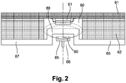
- the opening 66 is blind and forms a housing for the target 60.
- the target 60 is carried by a support 85 mounted on the shaft 19.
- This housing 66 is formed by a recess 86 of the wall 65 of the machine.
- This wall 65 is in the example described a rear plate 87 of the electric machine, opposite for example on the machine side where the compressor wheel is located.
- This back plate 87 is for example made of material, in particular plastic or metal.
- the electronic card 62 has a through hole 90 which receives the sensor 61. This orifice 90 receives the recess 86 of the wall.
- a control card 91 is placed on the electronic card 62. This control card 91 carries the sensor 61, and this control card closes the hole 90 of the electronic card.
Landscapes
- Engineering & Computer Science (AREA)
- Power Engineering (AREA)
- Mechanical Engineering (AREA)
- General Engineering & Computer Science (AREA)
- Microelectronics & Electronic Packaging (AREA)
- Chemical & Material Sciences (AREA)
- Combustion & Propulsion (AREA)
- Compressor (AREA)
Claims (11)
- Elektrische Ausrüstung (1), insbesondere für ein Kraftfahrzeug, wobei diese elektrische Ausrüstung aufweist:- eine elektrische Maschine (7), die eine Drehwelle (19) aufweist,- ein auf die Drehwelle montiertes Ziel (60),- einen Sensor (61), der eingerichtet ist, um mit dem Ziel zu interagieren, insbesondere, um eine Information bezüglich der Winkelstellung der Drehwelle zu liefern,- eine Elektronikkarte (62; 91), die mindestens eine Datenverarbeitungseinheit (63) trägt, wobei der Sensor auf diese Karte montiert und elektrisch mit der Verarbeitungseinheit verbunden ist,wobei die elektrische Maschine eine Wand (65) insbesondere eines Gehäuses (8) aufweist, wobei die Wand mit einer Durchgangsöffnung (66) versehen ist, der gegenüber das Ziel angeordnet ist,
dadurch gekennzeichnet, dass die Öffnung ein Dichtungsorgan (70), insbesondere aus Kunststoff, aufnimmt, wobei das Dichtungsorgan ein in die Öffnung eingesetztes Bauteil ist. - Elektrische Ausrüstung nach dem vorhergehenden Anspruch, wobei das Ziel (60) ein magnetisches Ziel ist, das vorzugsweise eingerichtet ist, um ein Magnetfeld zu erzeugen, das sich axial im Wesentlichen gemäß einer Drehachse der Welle der elektrischen Maschine erstreckt, und der Sensor auf dieses Magnetfeld anspricht.
- Elektrische Ausrüstung nach einem der vorhergehenden Ansprüche, wobei das Ziel an einem Ende der Drehwelle (19) angeordnet ist.
- Elektrische Ausrüstung nach einem der vorhergehenden Ansprüche, wobei das Ziel sich mindestens teilweise in der Öffnung (66) erstreckt.
- Elektrische Ausrüstung nach einem der vorhergehenden Ansprüche, wobei die Öffnung an der Elektronikkarte (62) mündet.
- Elektrische Ausrüstung nach einem der vorhergehenden Ansprüche, wobei der Sensor (61) und das Ziel (60) sich beiderseits der Wand (65) befinden.
- Elektrische Ausrüstung nach einem der vorhergehenden Ansprüche, wobei der Sensor auf eine Seite der Elektronikkarte oder einer Kontrollkarte montiert ist, der Seite, die zur Öffnung (66) gerichtet ist.
- Elektrische Ausrüstung nach einem der vorhergehenden Ansprüche, wobei die Elektronikkarte einen elektrischen Anschluss (75) aufweist, um den Sensor und die Verarbeitungseinheit elektrisch miteinander zu verbinden, wobei dieser Anschluss sich in der Dicke der Elektronikkarte zwischen den zwei Seiten der Karte erstreckt.
- Elektrische Ausrüstung nach einem der vorhergehenden Ansprüche, wobei die Elektronikkarte sich im Wesentlichen lotrecht zur Achse der Welle der Maschine erstreckt.
- Elektrische Ausrüstung nach einem der vorhergehenden Ansprüche, die einen elektrischen Auflader des Kraftfahrzeugs bildet.
- Elektrische Ausrüstung nach dem vorhergehenden Anspruch, wobei der Lader einen Kühlkanal (50) aufweist, der eingerichtet ist, um mindestens eine Elektronikeinheit zu kühlen, die die Elektronikkarte aufweist, wobei dieser Kanal eine Kühlflüssigkeit, zum Beispiel Wasser, empfängt.
Applications Claiming Priority (1)
| Application Number | Priority Date | Filing Date | Title |
|---|---|---|---|
| FR1559682A FR3042328B1 (fr) | 2015-10-12 | 2015-10-12 | Equipement electrique, notamment pour vehicule automobile |
Publications (2)
| Publication Number | Publication Date |
|---|---|
| EP3157142A1 EP3157142A1 (de) | 2017-04-19 |
| EP3157142B1 true EP3157142B1 (de) | 2019-08-28 |
Family
ID=55752338
Family Applications (1)
| Application Number | Title | Priority Date | Filing Date |
|---|---|---|---|
| EP16190727.4A Active EP3157142B1 (de) | 2015-10-12 | 2016-09-27 | Elektrische ausstattung insbesondere für kraftfahrzeug |
Country Status (2)
| Country | Link |
|---|---|
| EP (1) | EP3157142B1 (de) |
| FR (1) | FR3042328B1 (de) |
Families Citing this family (5)
| Publication number | Priority date | Publication date | Assignee | Title |
|---|---|---|---|---|
| JP6663467B2 (ja) | 2017-11-22 | 2020-03-11 | 三菱重工業株式会社 | 遠心圧縮機及び過給機 |
| US12136855B2 (en) | 2018-10-26 | 2024-11-05 | Borgwarner Inc. | Rotating machine including an impeller wheel, and at least one target element and at least one sensor to determine angular position of the impeller wheel |
| FR3088501B1 (fr) * | 2018-11-08 | 2021-10-22 | Valeo Equip Electr Moteur | Dispositif de detection de la position angulaire d'un rotor d'une machine electrique tournante |
| CN110486290A (zh) * | 2019-08-02 | 2019-11-22 | 中国航空工业集团公司金城南京机电液压工程研究中心 | 一种屏蔽泵 |
| FR3123701B1 (fr) * | 2021-06-08 | 2023-09-15 | Renault Sas | Boite de vitesse possédant un capteur magnétique étanche |
Citations (1)
| Publication number | Priority date | Publication date | Assignee | Title |
|---|---|---|---|---|
| US20120031215A1 (en) * | 2009-03-24 | 2012-02-09 | Magna Powertrain Ag & Co Kg | Transmission unit |
Family Cites Families (3)
| Publication number | Priority date | Publication date | Assignee | Title |
|---|---|---|---|---|
| DE102011089667A1 (de) * | 2011-12-22 | 2013-06-27 | Robert Bosch Gmbh | Elektrische Maschine |
| EP2924261B1 (de) * | 2012-11-22 | 2019-09-25 | Mitsubishi Heavy Industries Engine & Turbocharger, Ltd. | Turbolader mit elektrischem motor und motorvorrichtung mit turbolader mit elektrischem motor |
| JP5850263B2 (ja) * | 2013-05-17 | 2016-02-03 | 株式会社デンソー | 駆動装置 |
-
2015
- 2015-10-12 FR FR1559682A patent/FR3042328B1/fr active Active
-
2016
- 2016-09-27 EP EP16190727.4A patent/EP3157142B1/de active Active
Patent Citations (1)
| Publication number | Priority date | Publication date | Assignee | Title |
|---|---|---|---|---|
| US20120031215A1 (en) * | 2009-03-24 | 2012-02-09 | Magna Powertrain Ag & Co Kg | Transmission unit |
Also Published As
| Publication number | Publication date |
|---|---|
| FR3042328B1 (fr) | 2018-09-07 |
| EP3157142A1 (de) | 2017-04-19 |
| FR3042328A1 (fr) | 2017-04-14 |
Similar Documents
| Publication | Publication Date | Title |
|---|---|---|
| EP3157142B1 (de) | Elektrische ausstattung insbesondere für kraftfahrzeug | |
| US9976561B2 (en) | Method for securing stator in high speed electric motors | |
| WO2014209870A1 (en) | Supercharger for a combustion engine | |
| EP3707805A1 (de) | Elektromagnetische axialflussmaschine mit einem gemeinsamen kühlkreislauf mit der maschine und ihrer elektronischen steuer- und energievorrichtung | |
| FR3050777B1 (fr) | Systeme de gestion d'air d'admission pour un moteur thermique de vehicule automobile | |
| WO2017042236A1 (fr) | Compresseur de sur-alimentation électrique | |
| EP3347975A1 (de) | Elektrischer verdichter | |
| FR3060896B1 (fr) | Compresseur electrique avec circuit de refroidissement | |
| FR3015143A1 (fr) | Machine electrique | |
| EP1201891A1 (de) | Elektrisch unterstützter Abgasturbolader | |
| FR3044711B1 (fr) | Compresseur electrique avec circuit de refroidissement | |
| WO2016207544A1 (fr) | Support de roulements | |
| FR3043137B1 (fr) | Compresseur electrique avec circuit de refroidissement | |
| WO2017055741A1 (fr) | Compresseur electrique | |
| FR3048033A1 (fr) | Compresseur electrique | |
| FR3041699A1 (fr) | Compresseur electrique | |
| FR3055366B1 (fr) | Systeme de gestion d'air d'admission pour un moteur thermique de vehicule automobile | |
| WO2017068293A1 (fr) | Compresseur electrique | |
| WO2017103354A1 (fr) | Compresseur electrique | |
| FR3048034A1 (fr) | Compresseur electrique | |
| WO2017046327A1 (fr) | Compresseur electrique | |
| FR3049994A1 (fr) | Compresseur electrique avec circuit de refroidissement | |
| WO2018073496A1 (fr) | Compresseur electrique avec circuit de refroidissement | |
| FR3074545A1 (fr) | Compresseur electrique avec systeme de fixation des roulements | |
| FR3041698A1 (fr) | Compresseur electrique |
Legal Events
| Date | Code | Title | Description |
|---|---|---|---|
| PUAI | Public reference made under article 153(3) epc to a published international application that has entered the european phase |
Free format text: ORIGINAL CODE: 0009012 |
|
| STAA | Information on the status of an ep patent application or granted ep patent |
Free format text: STATUS: REQUEST FOR EXAMINATION WAS MADE |
|
| 17P | Request for examination filed |
Effective date: 20160927 |
|
| AK | Designated contracting states |
Kind code of ref document: A1 Designated state(s): AL AT BE BG CH CY CZ DE DK EE ES FI FR GB GR HR HU IE IS IT LI LT LU LV MC MK MT NL NO PL PT RO RS SE SI SK SM TR |
|
| AX | Request for extension of the european patent |
Extension state: BA ME |
|
| STAA | Information on the status of an ep patent application or granted ep patent |
Free format text: STATUS: EXAMINATION IS IN PROGRESS |
|
| 17Q | First examination report despatched |
Effective date: 20170613 |
|
| GRAP | Despatch of communication of intention to grant a patent |
Free format text: ORIGINAL CODE: EPIDOSNIGR1 |
|
| STAA | Information on the status of an ep patent application or granted ep patent |
Free format text: STATUS: GRANT OF PATENT IS INTENDED |
|
| INTG | Intention to grant announced |
Effective date: 20190327 |
|
| GRAS | Grant fee paid |
Free format text: ORIGINAL CODE: EPIDOSNIGR3 |
|
| GRAA | (expected) grant |
Free format text: ORIGINAL CODE: 0009210 |
|
| STAA | Information on the status of an ep patent application or granted ep patent |
Free format text: STATUS: THE PATENT HAS BEEN GRANTED |
|
| AK | Designated contracting states |
Kind code of ref document: B1 Designated state(s): AL AT BE BG CH CY CZ DE DK EE ES FI FR GB GR HR HU IE IS IT LI LT LU LV MC MK MT NL NO PL PT RO RS SE SI SK SM TR |
|
| REG | Reference to a national code |
Ref country code: GB Ref legal event code: FG4D Free format text: NOT ENGLISH |
|
| REG | Reference to a national code |
Ref country code: CH Ref legal event code: EP |
|
| REG | Reference to a national code |
Ref country code: AT Ref legal event code: REF Ref document number: 1173616 Country of ref document: AT Kind code of ref document: T Effective date: 20190915 |
|
| REG | Reference to a national code |
Ref country code: IE Ref legal event code: FG4D Free format text: LANGUAGE OF EP DOCUMENT: FRENCH |
|
| REG | Reference to a national code |
Ref country code: DE Ref legal event code: R096 Ref document number: 602016019299 Country of ref document: DE |
|
| REG | Reference to a national code |
Ref country code: NL Ref legal event code: MP Effective date: 20190828 |
|
| REG | Reference to a national code |
Ref country code: LT Ref legal event code: MG4D |
|
| PG25 | Lapsed in a contracting state [announced via postgrant information from national office to epo] |
Ref country code: PT Free format text: LAPSE BECAUSE OF FAILURE TO SUBMIT A TRANSLATION OF THE DESCRIPTION OR TO PAY THE FEE WITHIN THE PRESCRIBED TIME-LIMIT Effective date: 20191230 Ref country code: FI Free format text: LAPSE BECAUSE OF FAILURE TO SUBMIT A TRANSLATION OF THE DESCRIPTION OR TO PAY THE FEE WITHIN THE PRESCRIBED TIME-LIMIT Effective date: 20190828 Ref country code: SE Free format text: LAPSE BECAUSE OF FAILURE TO SUBMIT A TRANSLATION OF THE DESCRIPTION OR TO PAY THE FEE WITHIN THE PRESCRIBED TIME-LIMIT Effective date: 20190828 Ref country code: NO Free format text: LAPSE BECAUSE OF FAILURE TO SUBMIT A TRANSLATION OF THE DESCRIPTION OR TO PAY THE FEE WITHIN THE PRESCRIBED TIME-LIMIT Effective date: 20191128 Ref country code: NL Free format text: LAPSE BECAUSE OF FAILURE TO SUBMIT A TRANSLATION OF THE DESCRIPTION OR TO PAY THE FEE WITHIN THE PRESCRIBED TIME-LIMIT Effective date: 20190828 Ref country code: BG Free format text: LAPSE BECAUSE OF FAILURE TO SUBMIT A TRANSLATION OF THE DESCRIPTION OR TO PAY THE FEE WITHIN THE PRESCRIBED TIME-LIMIT Effective date: 20191128 Ref country code: HR Free format text: LAPSE BECAUSE OF FAILURE TO SUBMIT A TRANSLATION OF THE DESCRIPTION OR TO PAY THE FEE WITHIN THE PRESCRIBED TIME-LIMIT Effective date: 20190828 Ref country code: LT Free format text: LAPSE BECAUSE OF FAILURE TO SUBMIT A TRANSLATION OF THE DESCRIPTION OR TO PAY THE FEE WITHIN THE PRESCRIBED TIME-LIMIT Effective date: 20190828 |
|
| PG25 | Lapsed in a contracting state [announced via postgrant information from national office to epo] |
Ref country code: AL Free format text: LAPSE BECAUSE OF FAILURE TO SUBMIT A TRANSLATION OF THE DESCRIPTION OR TO PAY THE FEE WITHIN THE PRESCRIBED TIME-LIMIT Effective date: 20190828 Ref country code: LV Free format text: LAPSE BECAUSE OF FAILURE TO SUBMIT A TRANSLATION OF THE DESCRIPTION OR TO PAY THE FEE WITHIN THE PRESCRIBED TIME-LIMIT Effective date: 20190828 Ref country code: GR Free format text: LAPSE BECAUSE OF FAILURE TO SUBMIT A TRANSLATION OF THE DESCRIPTION OR TO PAY THE FEE WITHIN THE PRESCRIBED TIME-LIMIT Effective date: 20191129 Ref country code: ES Free format text: LAPSE BECAUSE OF FAILURE TO SUBMIT A TRANSLATION OF THE DESCRIPTION OR TO PAY THE FEE WITHIN THE PRESCRIBED TIME-LIMIT Effective date: 20190828 Ref country code: RS Free format text: LAPSE BECAUSE OF FAILURE TO SUBMIT A TRANSLATION OF THE DESCRIPTION OR TO PAY THE FEE WITHIN THE PRESCRIBED TIME-LIMIT Effective date: 20190828 Ref country code: IS Free format text: LAPSE BECAUSE OF FAILURE TO SUBMIT A TRANSLATION OF THE DESCRIPTION OR TO PAY THE FEE WITHIN THE PRESCRIBED TIME-LIMIT Effective date: 20191228 |
|
| REG | Reference to a national code |
Ref country code: AT Ref legal event code: MK05 Ref document number: 1173616 Country of ref document: AT Kind code of ref document: T Effective date: 20190828 |
|
| PG25 | Lapsed in a contracting state [announced via postgrant information from national office to epo] |
Ref country code: TR Free format text: LAPSE BECAUSE OF FAILURE TO SUBMIT A TRANSLATION OF THE DESCRIPTION OR TO PAY THE FEE WITHIN THE PRESCRIBED TIME-LIMIT Effective date: 20190828 |
|
| PG25 | Lapsed in a contracting state [announced via postgrant information from national office to epo] |
Ref country code: RO Free format text: LAPSE BECAUSE OF FAILURE TO SUBMIT A TRANSLATION OF THE DESCRIPTION OR TO PAY THE FEE WITHIN THE PRESCRIBED TIME-LIMIT Effective date: 20190828 Ref country code: PL Free format text: LAPSE BECAUSE OF FAILURE TO SUBMIT A TRANSLATION OF THE DESCRIPTION OR TO PAY THE FEE WITHIN THE PRESCRIBED TIME-LIMIT Effective date: 20190828 Ref country code: DK Free format text: LAPSE BECAUSE OF FAILURE TO SUBMIT A TRANSLATION OF THE DESCRIPTION OR TO PAY THE FEE WITHIN THE PRESCRIBED TIME-LIMIT Effective date: 20190828 Ref country code: EE Free format text: LAPSE BECAUSE OF FAILURE TO SUBMIT A TRANSLATION OF THE DESCRIPTION OR TO PAY THE FEE WITHIN THE PRESCRIBED TIME-LIMIT Effective date: 20190828 Ref country code: IT Free format text: LAPSE BECAUSE OF FAILURE TO SUBMIT A TRANSLATION OF THE DESCRIPTION OR TO PAY THE FEE WITHIN THE PRESCRIBED TIME-LIMIT Effective date: 20190828 Ref country code: AT Free format text: LAPSE BECAUSE OF FAILURE TO SUBMIT A TRANSLATION OF THE DESCRIPTION OR TO PAY THE FEE WITHIN THE PRESCRIBED TIME-LIMIT Effective date: 20190828 |
|
| PG25 | Lapsed in a contracting state [announced via postgrant information from national office to epo] |
Ref country code: SM Free format text: LAPSE BECAUSE OF FAILURE TO SUBMIT A TRANSLATION OF THE DESCRIPTION OR TO PAY THE FEE WITHIN THE PRESCRIBED TIME-LIMIT Effective date: 20190828 Ref country code: CZ Free format text: LAPSE BECAUSE OF FAILURE TO SUBMIT A TRANSLATION OF THE DESCRIPTION OR TO PAY THE FEE WITHIN THE PRESCRIBED TIME-LIMIT Effective date: 20190828 Ref country code: IS Free format text: LAPSE BECAUSE OF FAILURE TO SUBMIT A TRANSLATION OF THE DESCRIPTION OR TO PAY THE FEE WITHIN THE PRESCRIBED TIME-LIMIT Effective date: 20200224 Ref country code: MC Free format text: LAPSE BECAUSE OF FAILURE TO SUBMIT A TRANSLATION OF THE DESCRIPTION OR TO PAY THE FEE WITHIN THE PRESCRIBED TIME-LIMIT Effective date: 20190828 Ref country code: SK Free format text: LAPSE BECAUSE OF FAILURE TO SUBMIT A TRANSLATION OF THE DESCRIPTION OR TO PAY THE FEE WITHIN THE PRESCRIBED TIME-LIMIT Effective date: 20190828 |
|
| REG | Reference to a national code |
Ref country code: CH Ref legal event code: PL |
|
| REG | Reference to a national code |
Ref country code: DE Ref legal event code: R097 Ref document number: 602016019299 Country of ref document: DE |
|
| PLBE | No opposition filed within time limit |
Free format text: ORIGINAL CODE: 0009261 |
|
| STAA | Information on the status of an ep patent application or granted ep patent |
Free format text: STATUS: NO OPPOSITION FILED WITHIN TIME LIMIT |
|
| PG2D | Information on lapse in contracting state deleted |
Ref country code: IS |
|
| PG25 | Lapsed in a contracting state [announced via postgrant information from national office to epo] |
Ref country code: IE Free format text: LAPSE BECAUSE OF NON-PAYMENT OF DUE FEES Effective date: 20190927 Ref country code: LU Free format text: LAPSE BECAUSE OF NON-PAYMENT OF DUE FEES Effective date: 20190927 Ref country code: LI Free format text: LAPSE BECAUSE OF NON-PAYMENT OF DUE FEES Effective date: 20190930 Ref country code: CH Free format text: LAPSE BECAUSE OF NON-PAYMENT OF DUE FEES Effective date: 20190930 |
|
| REG | Reference to a national code |
Ref country code: BE Ref legal event code: MM Effective date: 20190930 |
|
| 26N | No opposition filed |
Effective date: 20200603 |
|
| PG25 | Lapsed in a contracting state [announced via postgrant information from national office to epo] |
Ref country code: BE Free format text: LAPSE BECAUSE OF NON-PAYMENT OF DUE FEES Effective date: 20190930 Ref country code: SI Free format text: LAPSE BECAUSE OF FAILURE TO SUBMIT A TRANSLATION OF THE DESCRIPTION OR TO PAY THE FEE WITHIN THE PRESCRIBED TIME-LIMIT Effective date: 20190828 |
|
| GBPC | Gb: european patent ceased through non-payment of renewal fee |
Effective date: 20200927 |
|
| PG25 | Lapsed in a contracting state [announced via postgrant information from national office to epo] |
Ref country code: CY Free format text: LAPSE BECAUSE OF FAILURE TO SUBMIT A TRANSLATION OF THE DESCRIPTION OR TO PAY THE FEE WITHIN THE PRESCRIBED TIME-LIMIT Effective date: 20190828 |
|
| PG25 | Lapsed in a contracting state [announced via postgrant information from national office to epo] |
Ref country code: HU Free format text: LAPSE BECAUSE OF FAILURE TO SUBMIT A TRANSLATION OF THE DESCRIPTION OR TO PAY THE FEE WITHIN THE PRESCRIBED TIME-LIMIT; INVALID AB INITIO Effective date: 20160927 Ref country code: MT Free format text: LAPSE BECAUSE OF FAILURE TO SUBMIT A TRANSLATION OF THE DESCRIPTION OR TO PAY THE FEE WITHIN THE PRESCRIBED TIME-LIMIT Effective date: 20190828 |
|
| PG25 | Lapsed in a contracting state [announced via postgrant information from national office to epo] |
Ref country code: GB Free format text: LAPSE BECAUSE OF NON-PAYMENT OF DUE FEES Effective date: 20200927 |
|
| PG25 | Lapsed in a contracting state [announced via postgrant information from national office to epo] |
Ref country code: MK Free format text: LAPSE BECAUSE OF FAILURE TO SUBMIT A TRANSLATION OF THE DESCRIPTION OR TO PAY THE FEE WITHIN THE PRESCRIBED TIME-LIMIT Effective date: 20190828 |
|
| P01 | Opt-out of the competence of the unified patent court (upc) registered |
Effective date: 20230528 |
|
| PGFP | Annual fee paid to national office [announced via postgrant information from national office to epo] |
Ref country code: DE Payment date: 20250916 Year of fee payment: 10 |
|
| PGFP | Annual fee paid to national office [announced via postgrant information from national office to epo] |
Ref country code: FR Payment date: 20250929 Year of fee payment: 10 |
|
| REG | Reference to a national code |
Ref country code: DE Ref legal event code: R081 Ref document number: 602016019299 Country of ref document: DE Owner name: VALEO ELECTRIFICATION, FR Free format text: FORMER OWNER: VALEO SYSTEMES DE CONTROLE MOTEUR, CERGY SAINT CHRISTOPHE, FR |